1
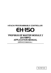
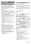
HITACHI PROGRAMMABLE CONTROLLER EtherCAT® Slave Controller (EH-IOCA) APPLICATION MANUAL (SERVICE MANUAL) NJI-599(X) ○ Warranty period and coverage The warranty period is the shorter period either 18 months from the data of manufacture or 12 months from the date of installation. However within the warranty period, the warranty will be void if the fault is due to; (1) Incorrect use as directed in this manual and the application manual. (2) Malfunction or failure of external other devices than this unit. (3) Attempted repair by unauthorized personnel. (4) Natural disasters. The warranty is for the PLC only, any damage caused to third party equipment by malfunction of the PLC is not covered by the warranty. ○ Repair Any examination or repair after the warranty period is not covered. And within the warranty period ant repair and examination which results in information showing the fault was caused by ant of the items mentioned above, the repair and examination cost are not covered. If you have ant questions regarding the warranty please contact with your supplier or the local Hitachi Distributor. (Depending on failure part, examination might be impossible.) ○ Ordering parts or asking questions When contacting us for repair, ordering parts or inquiring about other items, please have the following details ready before contacting the place of purchase. (1) Model (2) Manufacturing number (MFG.No.) (3) Details of the malfunction ○ Reader of this manual This manual is described for the following person. ・Person considering the introduction of PLC ・PLC system engineer ・Person handling PLC ・Manager after installing PLC Warning (1) Reproduction of the contents of this manual, in whole or in part, without written permission of Hitachi-IES, is prohibited. (2) The content of this document may be changed without notice. (3) While efforts have been made to be accurate, if any wrong or missing information is found, please contact us. MS-DOS, Windows, and Windows NT are registered trademarks of America and other registered countries of Microsoft Corp. of the United States. EtherCAT ® is registered trademark and patented technology, licensed by Beckhoff Automation Gmbh, Germany. Safety Precautions Read this manual and related documents thoroughly before installing, operating, performing preventive maintenance or performing inspection, and be sure to use the unit correctly. Use this product after acquiring adequate knowledge of the unit, all safety information, and all cautionary information. Also, make sure this manual enters the possession of the chief person in charge of safety maintenance. Safety caution items are classifies as “Danger” and “Caution” in this document. DANGER : Identifies information about practice or circumstances, which may lead to personal injury or death, property damage, or economic loss. CAUTION : Identifies information about practice or circumstances, which may lead to personal injury, property damage, or economic loss. However, depending on the circumstances, items marked with CAUTION may result in major accidents. The both marks show important information. Be sure to follow the instructions. Icons for prohibited items and required items are shown below: : Identifies prohibition. For example, when open flames are prohibited, is indicated. : Identifies requirement. For example, when grounding must be performed, is indicated. 1. Installation CAUTION Use this product in an environment as described in the catalog or this document. If this product is used in an environment subject to high temperature, high humidity, excessive dust, corrosive gases, vibration or shock, it may result in electric shock, fire or malfunction. Be sure to install the PLC according to this manual. Failure to do so could result in damage by falling off, failure or malfunction. Do not allow foreign objects such as wire chips to enter the unit. They may become the cause of fire, malfunction or failure. 2. Wiring REQUIRED The PLC must be grounded (FE terminal). Failure to do so could result in injury to personnel or causing it to malfunction. CAUTION Always use the power supply voltage listed in specifications. Using other voltage may damage the equipment or present a risk of fire. The wiring operation should be performed by a qualified personnel. Failure to do so could result in fire, damage or electric shock. 3. Precautions when using the unit DANGER Do not touch the terminals while the power is on. There is a risk of electric shock. Appropriate emergency stop circuit, interlock circuitry and similar safety measures should be added to the PLC system to ensure safety in the event of incorrect, missing or abnormal signals caused by broken signal lines, momentary power interruptions or other causes. Do not share the power supply of relay output module and interlock circuitry because relay output might not work properly due to switching noise from interlock circuitry. CAUTION When performing program change, forced output, RUN, STOP, etc., while the unit is running, be sure to check system safety carefully. Failure to do so could lead to damage to equipment. Supply power according to the power–up order. Failure to do so could lead to damage to equipment or malfunction. CAUTION USE POWER SUPPLY UNIT OF EH-PS SERIES FOR SUPPLYING ELECTRIC POWER. 4. Preventive maintenance DANGER Do not connect the +/- of the battery in reverse polarity. Do not recharge, disassemble, heat, place in fire, or short circuit the battery. There is a risk of explosion or fire. PROHIBITED Do not attempt to disassemble, repair or modify any part of the PLC. Electric shock, malfunction or failure may result. CAUTION Turn off power to the PLC before mounting or dismounting the module Electric shock, malfunction or failure may result. Revision History No. 1 Description of revision The first edition Date of revision Manual number Mar. 2014 NJI-599(X) Table of Contents Chapter 1 Introduction 1-1 to 1-2 1.1 Before use..................................................................................................................................... 1-1 1.2 Item packaged with the module .................................................................................................... 1-1 1.3 Combination with the EtherCAT® masters .................................................................................... 1-2 Chapter 2 EtherCAT® network 2-1 to 2-1 ® 2.1 Feature of EtherCAT ................................................................................................................... 2-1 2.2 Feature of EH-IOCA ..................................................................................................................... 2-1 Chapter 3 Specifications of EH-IOCA 3-1 to 3-7 3.1 General Specifications .................................................................................................................. 3-1 3.2 Functional Specifications .............................................................................................................. 3-2 3.2.1 EH-IOCA supported modules .............................................................................. 3-3 3.3 Name and function of each part ................................................................................................... 3-5 Chapter 4 Installation 4-1 to 4-4 4.1 Mounting modules ........................................................................................................................ 4-1 4.2 Mountable slots for EH-IOCA ....................................................................................................... 4-2 4.3 Wiring EtherCAT® network ........................................................................................................... 4-2 4.3.1 Recommended cable ........................................................................................... 4-2 4.3.2 Connect communication cable ............................................................................ 4-3 4.4 Mount redundant power supply modules ( EH-PSR, EH-BS8R )................................................. 4-4 4.5 Mount expansion unit.................................................................................................................... 4-4 Chapter 5 EtherCAT® communications 5-1 to 5-15 5.1 CoE interface ................................................................................................................................ 5-1 5.2 ESI files ......................................................................................................................................... 5-2 5.3 Modular Device profile .................................................................................................................. 5-2 5.3.1 PDO mapping of each I/O module ....................................................................... 5-3 5.3.2 Mount example .................................................................................................... 5-6 5.3.3 Device status ....................................................................................................... 5-11 5.3.4 Device control ...................................................................................................... 5-14 5.4 Communication state transitions .................................................................................................. 5-15 Chapter 6 Troubleshooting 6-1 to 6-2 6.1 Error indicates ............................................................................................................................... 6-1 6.2 AL status code .............................................................................................................................. 6-2 Appendix 1 EtherCAT® object dictionary A-1 to A-7 MEMO Chapter 1 1.1 Introduction Before use Thank you very much for choosing Hitachi Programmable Controller (hereinafter referred to as PLC), EHV+ series. This manual explains how to use the EtherCAT® slave controller with the Hitachi EHV+ Programmable Controller. Read this manual thoroughly and keep for installation operations, maintenance checks and other procedures. The following documentation related to PLC is also available and should be used together with this manual. Table 1.1-1 List of Description materials Items EHV+ series ® EtherCAT Slave controller Title of document Manual number EHV+ APPLICATION MANUAL NJI-564*(X) EH-IOCA APPLICATION MANUAL ( This manual ) NJI-599*(X) * The alphabet between the number and (X) means version (A,B…) and the space means the first edition. 1.2 Item packaged with the module Great care has been taken in the manufacture of this product, but we advise that the following points are checked immediately after purchase. 1. Is the model the same one that you ordered? 2. Has the product been damaged in any way? 3. Are any of the accessories listed in Table 1.2-1 missing? Table 1.2-1 List of accessories supplied with the EH-IOCA No. Product name Model name Appearance Quantity Remarks ® 1 EtherCAT Slave controller EH-IOCA 1 2 Instruction manual NJI-578(X) 1 For applying CE marking (EMC direction). 3 Ferrite Core SFC-10 2 Please refer to 4.3.2 Connect communication cable. 1–1 Chapter 1 1.3 Introduction Combination with the EtherCAT® masters EH-IOCA has some cautions when using the EtherCAT® master is EHV+ CPU module or others. Please care in accordance with the following points. - If using the EtherCAT® master is EHV+ CPU module. The combination of EH-IOCA can be operated by EHV+ CPU module is shown below. Table 1.3-1 support EHV+ CPU module Product name Model name EHV+ series EHV-CPU1102 CPU module EHV-CPU1025 Supported CPU software ® Supported EtherCAT master version library version Ver.3.4.4.5 Ver.3.5.3.60 - If using the EtherCAT® master is others The EtherCAT® device profile model of EH-IOCA is modular device profile. So the EtherCAT® master must be able to operate modular device profile. If the EtherCAT® master can’t operate modular device profile, the EtherCAT® master can’t use EH-IOCA. 1–2 EtherCAT® network Chapter 2 2.1 Feature of EtherCAT® EtherCAT® (Ethernet Control Automation Technology) is a high-performance industrial network system that enables faster and more efficient communications based on Ethernet. It can communicate in short cycle time since Ethernet frame transmit for each node at high speed. 2.2 Feature of EH-IOCA EH-IOCA is slave controller on EtherCAT® protocol of industrial network. EH-IOCA is helpful as I/O controller of EtherCAT® system. ® EtherCAT master EHV+ series ® CPU module etc … EtherCAT master CAT5 or higher LAN cable (Maximum segment length 100m) EH-IOCA EH-IOCA Slave EH-IOCA Slave Redundancy power supply Slave I/O controller EH-IOCH2 Figure 2.2-1 Example of EH-IOCA system (1) Maximum I/O 1,408 points Since it is coupler type, any I/O modules can be freely and flexibly used up to 1,408 points of digital I/O or 176 channels of analog I/O. (2) Compatibility of EH-150 series Existing power supply units, base units and I/O modules of the EH-150 series can be used. (Several I/O modules are not supported. Refer to following pages for further information.) (3) High-speed response, high reliability The minimum communication cycle is 200 µs. In addition, it is possible to hold the output data at the communication error occurs. (4) Easy connectivity with EHV+ series It gives greatly reduced man-hour for the work such as wiring and configuration by using with EHV+ series CPU module that supports the EtherCAT® master function. 2–1 MEMO Chapter 3 3.1 Specifications of EH-IOCA General Specifications General specifications are shown in Table 3.1-1. There specifications are common in EH-150 series. Table 3.1-1 General specifications Item Specifications 0 to 55 C Operating ambient temperature -10 to 75 C Storage ambient temperature Operating ambient humidity 5 to 95 % RH (no condensation) Storage ambient humidity 5 to 95 % RH (no condensation) Vibration resistance Noise resistance Insulation resistance Dielectric withstand voltage Grounding Usage environment Conforms to IEC 60068-2-6 ○ Noise voltage 1,500 Vpp Noise pulse width 100 ns, 1μ (Noise created by the noise simulator is applied across the power supply modules’s input terminals. This is determined by this company’s measuring method.) ○ Based on IEC61131-2 ○ Static noise: 3,000V at metal exposed area 20 MΩ or more between the AC external and case ground (FE) terminal (based on 500 V DC) 1,500 V AC for 1 minute between the AC external terminal and case ground (FE) terminal Class D grounding (ground with power supply module) No corrosive gases, no excessive dust Structure Open, wall-mount type Cooling Natural air cooling 3–1 Chapter 3 3.2 Specifications of EH-IOCA Functional Specifications Functional specifications are shown in Table 3.2-1. Table 3.2-1 Functional Specifications Item Specifications EtherCAT® protocol Communication protocol Communication specifications Transmit modulation method Base band Transmit speed 100Mbps Physical layer 100BASE-TX (IEEE802.3) Connector RJ45 (IN, OUT) Topology Daisy-chain Recommended cable CAT5 or higher, STP cable Maximum segment length 100 m Communication cycle 200µs or over *1 Node address range 1 to 99:Setting by rotary switch 1 to 65,535:Setting by EtherCAT® master Process data Fixed PDO mapping Mailbox Support Cycle mode Free Run mode (asynchronous) Output hold Support Functional specifications Support base unit EH-BS3A/5A/6A/8A/11A/8R Number of modules 22 modules / EH-IOCA Number of I/O points 1,408 points: Digital I/O 176 ch : Analog I/O Expansion unit 1 Refresh time 500µs Self-check WDT check Error indication LED Current consumption 350mA *1 The communication cycle is dependent on the specification of the EtherCAT® Master. ! CAUTION Digital I/O module, Analog I/O module, Resistance temperature detective input module, Thermocouple input module, counter module and positioning module are supported on the base unit using EH-IOCA. Note that the others are not supported. Do not mount these modules on the slave base unit. For information on the ESI files for EH-IOCA, contact your local supplier. 3–2 Chapter 3 3.2.1 Specifications of EH-IOCA EH-IOCA supported modules EH-IOCA supported modules and units are shown in Table 3.2.1-1,2. Shaded modules and units had ceased in production. I/O Assignment symbol are mean to I/O type on the EtherCAT® network. Table 3.2.1-1 supported modules ( 1 / 2 ) Product name Power module Model name Specifications I/O Supported Assignment symbol EH-PSA Input 100 to 240 V AC, Output 5V DC 3.8A, 24V DC, 0.4A ○ - EH-PSD Input 21.6 to 26.4 V DC, Output 5 V DC 3.8 A ○ - EH-PSR Redundant power supply, Input 100 to 240 V AC, Output 5 V DC 5.6 A, (up to 45 deg ambient temp) ○ - EH-BS3A EH-BS5A 3 I/O modules installed. 5 I/O modules installed. ○ - ○ - EH-BS6A 6 I/O modules installed. ○ - EH-BS8A EH-BS11A EH-BS8R EH-BS3 EH-BS5 EH-BS8 8 I/O modules installed. 11 I/O modules installed. Redundant power supply, 8 I/O modules installed. 3 I/O modules installed. 5 I/O modules installed. 8 I/O modules installed. ○ ○ ○ × × × - - - - - - Input and output controller EH-IOC EH-IOCH EH-IOCH2 Input and output control module (1 unit/1expansion) Input and output control module (1 unit/1expansion) Input and output control module (1 unit/1expansion) × × ○ - - - Digital input module EH-XD8 EH-XD16 EH-XDL16 EH-XD32 EH-XDL32 EH-XD32E EH-XDL32E EH-XD32H EX-XD64 EH-XA16 EH-XAH16 8 points, 24 V DC input 16 points, 24 V DC input 16 points, 24 V DC input, Intensified filter 32 points, 24 V DC input 32 points, 24 V DC input, Intensified filter 32 points, 24 V DC input, Spring type terminal block 32 points, 24 V DC input, Spring type terminal block, Intensified filter 32 points, 24 V DC input, Connector compatible with EM/H-200 series 64 points, 24 V DC input 16 points, 100 to 120 V AC input 16 points, 200 to 240 V AC input ○ ○ ○ ○ ○ ○ ○ ○ ○ ○ ○ X16 X16 X16 X32 X32 X32 X32 X32 X64 X16 X16 ○ ○ ○ ○ ○ ○ ○ ○ ○ ○ ○ ○ Y16 Y16 Y16 Y16 Y16 Y16 Y16 Y16 Y16 Y32 Y32 Y32 ○ Y32 ○ Y32 EH-YT64 EH-YTP64 EH-YS4 EH-YS16 8 points, relay output (isolated contact point), 100/240 V AC, 24 V DC 12 points, relay output, 100/240 V AC, 24 V DC 16 points, relay output, 100/240 V AC, 24 V DC, 16 points/1 common 16 points, relay output, 100/240 V AC, 24 V DC, 8 points/1 common 8 points, transistor output, 12/24 V DC (sink type) 8 points, transistor output, 12/24 V DC (source type) 16 points, transistor output, 12/24 V DC (sink type) 16 points, transistor output, 12/24 V DC (source type) 16 points, transistor output, 12/24 V DC (source type) 32 points, transistor output, 12/24 V DC (sink type) 32 points, transistor output, 12/24 V DC (source type) 32 points, transistor output, 12/24 V DC (sink type), Spring terminal block 32 points, transistor output, 12/24 V DC (source type), Spring terminal block 32 points, transistor output, 5/12/24 V DC (sink type), Connector compatible with EM/H-200 series 64 points, transistor output, 12/24 V DC (sink type) 64 points, transistor output, 12/24 V DC (source type) 4 points, triac output, 100/240 V AC 16 points, triac output, 100/240 V AC ○ ○ ○ ○ Y64 Y64 Y16 Y16 EH-MTT32 16 points TTL output, 16 points TTL input, 4 to 27V DC ○ B1_1 Base unit Digital output EH-YR8B module EH-YR12 EH-YR16 EH-YR16D EH-YT8 EH-YTP8 EH-YT16 EH-YTP16 EH-YTP16S EH-YT32 EH-YTP32 EH-YT32E EH-YTP32E EH-YT32H TTL I/O module 3–3 Chapter 3 Specifications of EH-IOCA Table 3.2.1-2 supported modules ( 2 / 2 ) Product name Model name Specifications I/O Supported Assignment symbol Analog input module EH-AX44 EH-AX8V EH-AX8H EH-AX8I EH-AX8IO EH-AXH8M EH-AXG5M 12 bits analog input (4 to 20mA, 0 to 10 V) each 4 ch. 12 bits analog input 8 ch., Voltage (0 to +10 V) 12 bits analog input 8 ch., Voltage (-10 to +10 V) 12 bits analog input 8 ch., Current (4 to 20 mA) 12 bits analog input 8 ch., Current (0 to 22 mA) 14 bits analog input (0 to 22mA, 4 to 22mA, -10 to +10V, 0 to 10V) 8 ch. Isolated analog input (0 to 22mA, 4 to 22mA, -10 to +10V, 0 to 10V) 5 ch. ○ ○ ○ ○ ○ ○ ○ X8W X8W X8W X8W X8W X8W X8W Analog output module EH-AY22 EH-AY2H EH-AY4V EH-AY4H EH-AY4I EH-AYH8M EH-AYG4M 12 bits analog output (4 to 20mA, 0 to 10 V) each 2 ch. 12 bits analog output 2 ch., Voltage (-10 to +10 V) 12 bits analog output 4 ch., Voltage (0 to +10 V) 12 bits analog output 4ch., Voltage (-10 to +10 V) 12 bits analog output 4 ch., Current (4 to 20 mA) 14 bits analog output (0 to 22mA, 4 to 22mA, 0 to 10V) 8 ch. Isolated analog output (0 to 22mA, 4 to 22mA, -10 to +10V, 0 to 10V) 4 ch. 4 channels resistance bulb input, Signed 15 bits Platinum (Pt 100 / Pt 1000) ○ ○ ○ ○ ○ ○ ○ Y8W Y8W Y8W Y8W Y8W Y8W Y8W ○ X4W Signed 15 bits, Thermocouple input (K, E, J, T, B, R, S, N) 8 points ○ X8W ○ X5Y3W ○ X5Y3W RTD input module Thermocouple input module Counter module EH-PT4 EH-TC8 EH-CU EH-CUE 2 channels high-speed counter input, Maximum frequency of 100 kHz, 1/ 2-phases switchover, 4-point opened collector output 1 channel high-speed counter input, Maximum frequency of 100 kHz, 1 /2-phases switchover, 2-point opened collector output Positioning module EH-POS EH-POS4 1-axis pulse positioning module 4-axes pulse positioning module ○ × X4Y4W X4Y4W Communication and network module EH-SIO Serial communication module, RS-232C / RS-422 / RS-485 general-purpose, Modbus protocol, Hi-Protocol, Simple data link Ethernet module IEEE802.3 standard, 10BASE-T Ethernet module IEEE802.3 standard, 10BASE-T/ 100BASE-TX (Auto negotiation) CPU link module (coaxial) CPU link module (optical fiber) CPU link module (support optical fiber GI50/125m cable) CPU link module (support optical fiber GI62.5/125m cable) Compact remote master module, Twisted pair cable Compact remote slave module, Twisted pair cable Compact remote 2 master module, Twisted pair cable Compact remote 2 slave module, Twisted pair cable Compact LINK module, Twisted pair cable Compact I/O LINK module, Twisted pair cable Device Net master module Device Net slave controller, 256 words input / 256 words output PROFIBUS-DP master module PROFIBUS-DP slave controller, 208 words input / output × - × × - - × × × × × × × × × × × × × × - - - - - - - - - - - - - - Module for an opened slot ○ -*2 EH-ETH EH-ETH2 EH-LNK EH-OLNK EH-OLNKG EH-OLNKE EH-TRMME EH-TRMLE EH-TRME2 EH-TRLE2 EH-TLNKE EH-TRLLE EH-RMD EH-IOCD EH-RMP EH-IOCP Dummy module EH-DUM *1 If unsupported modules are mounted on the base of EH-IOCA, EH-IOCA may malfunction. *2 If dummy modules are mounted on the base of EH-IOCA, I/O assignment symbol is not displayed. 3–4 Chapter 3 3.3 Specifications of EH-IOCA Name and function of each part Name and function of each part 1] Lock button Model name EH-IOCA Weight 0.14 kg (0.31 lb) Current consumption (5VDC) 0.35 A Dimensions (mm (in.)) 2] LED display 3] Node address switch 45 (1.77) 95 (3.74) 100 (3.94) 4] Reset switch 5] Communication connector (IN) 6] Communication connector (OUT) No. Name Function 1] Lock button Press this button to dismount. Module can be fixed firmly by a screw of M4 × 10mm (0.39in). 2] LED display The status of module is displayed on this LED. 3] Node address switch This is a switch to set the node address. 4] Reset switch The module can be reset by pressing this switch when error such as the module abnormal occurred. 5] Communication connector (IN) This is a connector to connect a cable for communication. 6] Communication connector (OUT) This is a connector to connect a cable for communication. 3–5 Remarks Chapter 3 Specifications of EH-IOCA Description of LED display LED name LED Indication Details Power supply On : indicates that the DC5V power is supplied. (Green) Off : indicates that the DC5V power is not supplied or reset switch is on. POW Display an EtherCAT® communication status. State Status (Green) RUN EtherCAT EH-IOCA POW Details Off Init Blinking PRE-OPERATIONAL Single-flash SAFE-OPERATIONAL On RUN ERR OPERATIONAL ® Display EtherCAT error status or EH-IOCA hardware status. Error (Red) ERR State Details Off No error Blinking Configuration error Single-flash EtherCAT® synchronism failure Communication data failure Double-flash Application watchdog timeout Flickering Boot error On PDI watchdog timeout The state of LED is indicated below. ON Blinking 200ms 200ms OFF ON Single-flash 200ms 1000ms 200ms OFF ON Double-flash 200ms 200ms 200ms OFF 50ms ON Flickering OFF 3–6 1000ms 200ms Chapter 3 Specifications of EH-IOCA Description of Rotary switch Rotary switch ×10 6 5 4 7 8 3 2 9 0 1 Symbol Meaning Details of setting U Station No. The station No. of EtherCAT® network is set from 1 to 99. (upper) (1 to 99) The tens place set by upper rotary switch. The ones place set by lower rotary switch. ID ×1 6 5 4 7 8 3 2 9 0 1 L (lower) [Default setting: U=0, L=0] Node address of EH-IOCA is set by node address method of EtherCAT® master unit. If EtherCAT® master use fixed node address method, rotary switch of EH-IOCA is valid. If EtherCAT® master use logic node address method or auto increment address method, rotary switch of EH-IOCA is invalid. If EtherCAT® master use logic nodes address method or auto increment address method, please set the rotary switch to “00”. Description of Connector Connector Symbol Indication Details IN Communication connector RJ45 8-pin connector. Terminal layouts are shown below. LINK Pin No. 1 IN ACT 8 OUT LINK 1 OUT ACT 8 LINK LINK LED (Green) ACT ACT LED Details 1 Send data + (TD+) 2 Send data - (TD-) 3 Receive data + (RD+) 4 NC 5 NC 6 Receive data - (RD-) 7 NC 8 NC LINK LED light up if the communication device are connected with a cable. ACT LED is flashing during operation. (Orange) Please refer to “4.3 Wiring EtherCAT® network” for the wiring of connector. 3–7 MEMO Chapter 4 4.1 Installation Mounting modules (1) Mounting 1] Hook the lower part of the module to the hole in ② the base. 2] Press in the upper side of the module until it clicks. Note 1: Make sure the module is mounted securely. ① Note 2: Slot position of power supply module is fixed as 1st slot of base unit. Note 3: Slot position of CPU module is fixed as 2nd slot of base unit. Modules can be fixed firmly by M4×10mm screws. Figure 4.1-1 Mounting Module (2) Removing ① ③ 1] Press the lock button. 2] With the lock button pressed, pull the top of the module. ② 3] Pull the unit away from the base unit. Note: Press the lock button for a power supply module. Figure 4.1-2 Removing Module 4–1 Chapter 4 4.2 Installation Mountable slots for EH-IOCA EH-IOCA is mountable on only slot for CPU (right side of power supply module). Slot No. 0 1 2 3 4 5 6 7 Et Figure 4.2-1 Mountable slots for EH-IOCA 4.3 Wiring EtherCAT® network 4.3.1 Recommended cable Recommended cable of EH-IOCA is shown below. But if EH-IOCA is used in noisy environment, we recommend cables with double, aluminum tape and braided shielding. Table 4.3.1-1 Recommended cable of EH-IOCA Item Details Twisted pair cable 100BASE-TX (CAT 5 or higher) STP cable RJ45 connector CAT 5 or higher, Shielded The maximum cable length between connected nodes is 100m. Note that some cables do not guarantee 100m. In general, if the conductors are strand wire, the transmission performance will be lower than solid wire and the operation at 100m distance cannot be guaranteed. Confirm details with the cable manufacturer. 4–2 Chapter 4 Installation 4.3.2 Connect communication cable Connect the communication cable from EtherCAT® master unit to the IN connector of EH-IOCA. Connect another communication cable from OUT connector of the first slave unit to the IN connector of next slave unit. Note that nothing should be connected to the OUT connector of the slave unit at the terminal end of the network. EtherCAT master unit E R EP E L/ L/ L R Slave unit Slave unit Terminal slave unit Figure 4.3.2-1 Connect communication cable Connect the connector of the communications cable surely. Do not put the communications cable in a duct same as other power lines and a wiring duct of I/O. Separate approximately 300mm from other ducts. It may be improved when put a ferrite core in a cable as measures to the induction noise for the communications cables. ! ! CAUTION When EH-IOCA gets into communication with EtherCAT® master unit, the communication may not establish depending on the master unit. In that case, follow the operations below. 1] Reconnect the connector of the communication cable. 2] Reboot EH-IOCA. CAUTION If EH-IOCA is applied for CE marking (EMC direction), follow the instructions below. 1] Communication cable must be routed in metal duct separated from power or I/O cables as much as possible. 2] Use included ferrite core for communication cable with one turn as the picture below. Communication connector Communication cable Ferrite core 19.0 x 19.0 x 30.0mm Figure 4.3.2-2 Use ferrite core 4–3 Chapter 4 4.4 Installation Mount redundant power supply modules (EH-PSR, EH-BS8R) If you use EH-PSR and EH-BS8R, it must use breaker to each power supply modules. EH-IOCA Redundant power supply EH-PSR EH-BS8R FFB FFB Figure 4.4-1 Use redundant power supply If you use power operation monitor of redundant power supply, please refer to the section “5.3.2 Mount example”. 4.5 Mount expansion unit EH-IOCA can use one expansion unit use by EH-IOCH2. Then rotary switch of EH-IOCH2 must be set 1. Expansion unit can use redundant power supply. Redundant power supply EH-IOCA Basic unit FFB FFB Expansion cable (EH-CB**A) Redundant power supply EH-IOCH2 EH-PSR Expansion unit EH-BS8R FFB FFB Figure 4.5-1 Use expansion unit 4–4 EtherCAT® communications Chapter 5 5.1 CoE interface EH-IOCA use “CAN application protocol over EtherCAT® ( CoE )”, a communication interface to be applied for EtherCAT® devices, as the device profile of the open network standard “CAN application protocol”. Application Object Dictionary PDO Mapping TCP, UDP File Access IP EoE SDO FoE SoE PDO CoE Mailbox CoE Process Data EtherCAT Slave Controller Physical Layer Application of EH-IOCA Figure 5.1-1 Application of EH-IOCA CoE has two types of object dictionaries, PDO (process data object) and SDO (service data object). PDO is composed of object dictionaries that can be mapped. The process data is defined by PDO mapping. PDO is used in PDO communications for regularly exchanging process data. SDO is able to read and write all object dictionaries and is used in non-fixed-cycle type SDO (event type messages) communications. EH-IOCA handles the data refreshing of each module and status information by PDO communication, and EH-IOCA handles the information of EH-IOCA (Device type, Vender ID etc…) by SDO communication. 5–1 Chapter 5 5.2 EtherCAT® communications ESI files Parameters of EtherCAT® slaves are defined by ESI files. Each ESI file defines Vender ID, Device group, PDO mapping, and sync manager. ENI file that includes the network configuration information is produced by installing ESI files in the configuration tool. EtherCAT® master unit can operate by writing (downloading) ENI file. ESI file Import Configurator ESI file Export ESI file Download ENI file EtherCAT master Figure 5.2-1 ESI files For information on the ESI files for EH-IOCA, contact your local supplier. 5.3 Modular Device Profile Device profile model of EH-IOCA conforms EtherCAT® Modular Device Profile. I/O modules are fixed mapping in PDO mapping table by the module. Figure 5.3-1 Modular Device Profile RxPDO and TxPDO are handled in case of cyclic data transfer. Input Entries, Output Entries, Configuration Parameter, Information, Communication Area, Device Parameter are handled by SDO communication. 5–2 Chapter 5 EtherCAT® communications 5.3.1 PDO mapping of each I/O module EH-IOCA assigns each I/O module position and module information to mapping table when EH-IOCA is power on. Mapped index can’t be changed. Mounted modules are defined RxPDO and TxPDO, and resisted SM Assignment Lists. SM Assignment Lists can’t be changed by user. Slot 0 Slot 1 RxPDOs(Output) 0x1600 0x1601 0x1602 Output Entries 0x7000:SI0,1 0x7010:SI0,1 0x7020:SI0,1 TxPDOs(Input) 0x1A00 0x1A01 0x1A02 Input Entries 0x6000:SI0,1 0x6010:SI0,1 0x6020:SI0,1 E R EP E L/ L/ Slot 2 I/O modules list Slot 0: EH-XD16 Slot 1: Empty Slot 2: EH-YT16 R Figure 5.3.1-1 EH-IOCA mapping The relations between each module mounted position and module number on the EtherCAT® network are shown below. Table 5.3.1-1 Slot position and module number 1 Table 5.3.1-2 Slot position and module number 2 Slot position Module No. Slot position Module No. Basic unit slot 0 Module 1 Expansion unit slot 0 Module 12 Basic unit slot 1 Module 2 Expansion unit slot 1 Module 13 Basic unit slot 2 Module 3 Expansion unit slot 2 Module 14 Basic unit slot 3 Module 4 Expansion unit slot 3 Module 15 Basic unit slot 4 Module 5 Expansion unit slot 4 Module 16 Basic unit slot 5 Module 6 Expansion unit slot 5 Module 17 Basic unit slot 6 Module 7 Expansion unit slot 6 Module 18 Basic unit slot 7 Module 8 Expansion unit slot 7 Module 19 Basic unit slot 8 Module 9 Expansion unit slot 8 Module 20 Basic unit slot 9 Module 10 Expansion unit slot 9 Module 21 Basic unit slot 10 Module 11 Expansion unit slot 10 Module 22 The relations between each module number and index are shown Table 5.3.1-3, 5.3.1-4, 5.3.1-5, 5.3.1-6. 5–3 Chapter 5 EtherCAT® communications Table 5.3.1-3 Each module number object address 1 ® EtherCAT object dictionary Module number 1 2 3 4 5 6 RxPDOs 0x1600 0x1601 0x1602 0x1603 0x1604 0x1605 TxPDOs 0x1A00 0x1A01 0x1A02 0x1A03 0x1A04 0x1A05 Input Entries 0x6000 0x6010 0x6020 0x6030 0x6040 0x6050 Output Entries 0x7000 0x7010 0x7020 0x7030 0x7040 0x7050 Configuration Parameter 0x8000 0x8010 0x8020 0x8030 0x8040 0x8050 Information 0x9000 0x9010 0x9020 0x9030 0x9040 0x9050 Table 5.3.1-4 Each module number object address 2 ® EtherCAT object dictionary Module number 7 8 9 10 11 - RxPDOs 0x1606 0x1607 0x1608 0x1609 0x160A - TxPDOs 0x1A06 0x1A07 0x1A08 0x1A09 0x1A0A - Input Entries 0x6060 0x6070 0x6080 0x6090 0x60A0 - Output Entries 0x7060 0x7070 0x7080 0x7090 0x70A0 - Configuration Parameter 0x8060 0x8070 0x8080 0x8090 0x80A0 - Information 0x9060 0x9070 0x9080 0x9090 0x90A0 - Table 5.3.1-5 Each module number object address 3 ® EtherCAT object dictionary Module number 12 13 14 15 16 17 RxPDOs 0x160B 0x160C 0x160D 0x160E 0x160F 0x1610 TxPDOs 0x1A0B 0x1A0C 0x1A0D 0x1A0E 0x1A0F 0x1A10 Input Entries 0x60B0 0x60C0 0x60D0 0x60E0 0x60F0 0x6100 Output Entries 0x70B0 0x70C0 0x70D0 0x70E0 0x70F0 0x7100 Configuration Parameter 0x80B0 0x80C0 0x80D0 0x80E0 0x80F0 0x8100 Information 0x90B0 0x90C0 0x90D0 0x90E0 0x90F0 0x9100 Table 5.3.1-6 Each module number object address 4 ® EtherCAT object dictionary Module number 18 19 20 21 22 - RxPDOs 0x1611 0x1612 0x1613 0x1614 0x1615 - TxPDOs 0x1A11 0x1A12 0x1A13 0x1A14 0x1A15 - Input Entries 0x6110 0x6120 0x6130 0x6140 0x6150 - Output Entries 0x7110 0x7120 0x7130 0x7140 0x7150 - Configuration Parameter 0x8110 0x8120 0x8130 0x8140 0x8150 - Information 0x9110 0x9120 0x9130 0x9140 0x9150 - 5–4 Chapter 5 EtherCAT® communications Data sizes of each I/O assignment symbol are shown below. Input modules are assigned 0x60nn sub-index 1. Output modules are assigned 0x70nn sub-index 1. (“nn” is slot position. ) Table 5.3.1-7 Data sizes of each I/O assignment symbol I/O assignment Device ID Input sizes Output sizes (Rx) (Tx) Data type symbol X16 0x00000001 UINT 2 bytes - X32 0x00000002 UDINT 4 bytes - X64 0x00000003 ULINT 8 bytes - X4Y4W 0x00000004 ARRAY [0..3] OF UINT 8 bytes 8 bytes / ARRAY [0..3] OF UINT Y16 0x00000005 UINT - 2 bytes Y32 0x00000006 UDINT - 4 bytes Y64 0x00000007 ULINT - 8 bytes B1_1 0x00000008 UINT/UINT 2 bytes 2 bytes B2_1 0x00000009 UDINT/UINT 4 bytes 2 bytes B1_2 0x0000000A UINT/UDINT 2 bytes 4 bytes B2_2 0x0000000B UDINT/UDINT 4 bytes 4 bytes X4W 0x00000011 ARRAY [0..3] OF UINT 8 bytes - X8W 0x00000012 ARRAY [0..7] OF UINT 16 bytes - X7Y1W 0x00000013 ARRAY [0..6] OF UINT 14 bytes 2 bytes 12 bytes 4 bytes 10 bytes 6 bytes 6 bytes 10 bytes 4 bytes 12 bytes 2 bytes 14 bytes / ARRAY [0..0] OF UINT X6Y2W 0x00000014 ARRAY [0..5] OF UINT / ARRAY [0..1] OF UINT X5Y3W 0x00000015 ARRAY [0..4] OF UINT / ARRAY [0..2] OF UINT X3Y5W 0x00000016 ARRAY [0..2] OF UINT / ARRAY [0..4] OF UINT X2Y6W 0x00000017 ARRAY [0..1] OF UINT / ARRAY [0..5] OF UINT X1Y7W 0x00000018 ARRAY [0..0] OF UINT / ARRAY [0..6] OF UINT Y8W 0x00000019 ARRAY [0..7] OF UINT - 16 bytes Y4W 0x0000001A ARRAY [0..3] OF UINT - 8 bytes For information on relation between model name of I/O modules and I/O assignment symbol, please refer to “3.2 Functional Specifications”. 5–5 EtherCAT® communications Chapter 5 5.3.2 Mount example (1) If you use only basic unit. 1 2 3 4 5 6 7 8 9 10 11 E R EP E L/ L/ R Item Model name I/O assignment Item Model name I/O assignment symbol symbol Power supply module EH-PSA - Module 6 Empty - Base unit EH-BS8A - Module 7 EH-CU X5Y3W Module 1 EH-XD16 X16 Module 8 EH-AY8H Y8W Module 2 EH-YT16 Y16 Module 9 EH-POS X4Y4W Module 3 EH-YT32 Y32 Module 10 Empty - Module 4 EH-AX8V X8W Module 11 Empty - Module 5 EH-XD64 X64 Table 5.3.2-1 Case 1 PDO mapping Module number Item 1 2 3 4 5 6 ARRAY Input type UINT - - - UINT UDINT 8 ARRAY [0..7] OF ULINT - UINT Output type 7 [0..4] OF - - 10 11 - - - - ARRAY - UINT - 9 [0..3] OF UINT ARRAY ARRAY ARRAY [0..2] OF [0..7] OF [0..3] OF UINT UINT UINT RxPDOs - 0x1601 0x1602 - - - 0x1606 0x1607 0x1608 - - Output Entries - 0x7010:01 0x7020:01 - - - 0x7060:01 0x7070:01 0x7080:01 - - TxPDOs 0x1A00 - - 0x1A03 0x1A04 - 0x1A06 - 0x1A08 - - Input Entries 0x6000:01 - - 0x6030:01 0x6040:01 - 0x6060:01 - 0x6080:01 - - 5–6 Chapter 5 EtherCAT® communications (2) If you use expansion unit. 1 2 3 4 5 E R EP E L/ L/ ! Caution ・EH-IOCA can expand a one unit. ・Rotary switch of EH-IOCH2 must be set 1. ・Module number of expansion unit is starting from 12 regardless of basic unit base type. R 12 13 14 15 16 17 18 19 20 21 22 Item Model I/O assignment name symbol Power supply module EH-PSA - Module 14 EH-POS X4Y4W Base unit EH-BS8A - Module 15 EH-AXG5M X8W Module 1 EH-XD32 X32 Module 16 Empty - Module 2 EH-YT64 Y64 Module 17 Empty - Module 3 EH-YT32 Y32 Module 18 EH-XD64 X64 Module 4 EH-PT4 X4W Module 19 EH-YT16 Y16 Module 5 EH-XD16 X16 Module 20 Empty - Module 12 EH-MTT32 B1/1 Module 21 EH-YT32 Y32 Module 13 EH-AYG4M Y8W Module 22 EH-PT4 X4W 5–7 Item Model name I/O assignment symbol Chapter 5 EtherCAT® communications Table 5.3.2-2 Case 2 PDO mapping (basic unit) Modules number Item 1 2 3 4 5 6 7 8 9 10 11 UINT - - - - - - ARRAY Input type UDINT - - [0..3] OF UINT Output type - ULINT UDINT - - - - - - - - RxPDOs - 0x1601 0x1602 - - - - - - - - Output Entries - 0x7010:01 0x7020:01 - - - - - - - - TxPDOs 0x1A00 - - 0x1A03 0x1A04 - - - - - - Input Entries 0x6000:01 - - 0x6030:01 0x6040:01 - - - - - - Table 5.3.2-3 Case 2 PDO mapping (expansion unit) Modules number Item 12 Input type Output type UINT UINT 13 - 14 15 ARRAY ARRAY [0..3] OF [0..7] OF UINT UINT ARRAY ARRAY [0..7] OF [0..3] OF UINT UINT 16 17 18 19 20 21 22 ARRAY - - ULINT - - - [0..3] OF UINT - - - - UINT - UDINT - RxPDOs - 0x160C 0x160D - - - - 0x1612 - 0x1614 - Output Entries - 0x70C0:01 0x70D0:01 - - - - 0x7120:01 - 0x7140:01 - TxPDOs 0x1A0B - 0x1A0D 0x1A0E - - 0x1A11 - - - 0x1A15 Input Entries 0x60B0:01 - 0x60D0:01 0x60E0:01 - - 0x6110:01 - - - 0x6150:01 5–8 Chapter 5 EtherCAT® communications (3) If you use redundant power supply 1 2 3 4 5 6 7 8 11 E R EP E L/ L/ R ! 12 13 14 15 16 17 18 19 Item 22 Caution Power operation monitors of redundant power supply are shown below. Basic unit: Module 11 Expansion unit: Module 22 Model I/O assignment Item Model name I/O assignment name symbol Power supply module EH-PSR - Module 11 EH-PSR*1 X16 Base unit EH-BS8R - Module 12 EH-CU X5Y3W Module 1 EH-XD32 X32 Module 13 EH-CUE X5Y3W Module 2 Empty - Module 14 EH-AYH8M Y8W Module 3 EH-XD32 X32 Module 15 EH-AYH8M Y8W Module 4 Empty - Module 16 Empty - Module 5 EH-YT32 Y32 Module 17 Empty - Module 6 EH-YT32 Y32 Module 18 EH-YTP16 Y16 Module 7 EH-AXH8M X8W Module 19 EH-YTP16 Y16 Module 8 EH-AXH8M X8W Module 22 EH-PSR*1 X16 symbol *1 Power operation monitor 5–9 Chapter 5 EtherCAT® communications Table 5.3.2-4 Case 3 PDO mapping (basic unit) Modules number Item 1 Input type UDINT 2 3 - 4 - UDINT 5 6 - - 7 8 ARRAY ARRAY [0..7] OF [0..7] OF UINT UINT 9 10 11 - - UINT Output type - - - - UDINT UDINT - - - - - RxPDOs - - - - 0x1604 0x1605 - - - - - Output Entries - - - - 0x7040:01 0x7050:01 - - - - - TxPDOs 0x1A00 - 0x1A02 - - - 0x1A06 0x1A07 - - 0x1A0A Input Entries 0x6000:01 - 0x6020:01 - - - 0x6060:01 0x6070:01 - - 0x60A0:01 Table 5.3.2-5 Case 3 PDO mapping (expansion unit) Modules number Item 14 15 16 17 18 19 20 21 22 - - - - UINT UINT - - UINT ARRAY ARRAY ARRAY [0..2] OF [0..2] OF [0..7] OF [0..7] OF - - - - - - - UINT UINT UINT UINT RxPDOs 0x160B 0x160C 0x160D 0x160E - - - - - - - Output Entries 0x70B0:01 0x70C0:01 0x70D0:01 0x70E0:01 - - - - - - - TxPDOs 0x1A0B 0x1A0C - - - - 0x1A11 0x1A12 - - 0x1A15 Input Entries 0x60B0:01 0x60C0:01 - - - - 0x6110:01 0x6120:01 - - 0x6150:01 Input type Output type 12 13 ARRAY ARRAY [0..4] OF [0..4] OF UINT UINT ARRAY 5 – 10 Chapter 5 EtherCAT® communications 5.3.3 Device status EtherCAT® has Device status function which can send the internal status of each node device to the master unit. Index of device status is 0xF100. Device status of EH-IOCA is shown below. Table 5.3.3-1 Device status (0xF100) Sub-index Item 1 Status 2 Module RES 3 Module WDT 4 Module FAIL 5 Module IDER 6 FPGA Version 7 CPU Version Information of each item is shown below. (1) Status Bit No. Name 0 WDTEN Meaning Description 0: Watchdog error This bit is always ON. 1: No error 1 2 3 4 0: Normal Some I/O modules are reset state. 1: Modules reset For information, please refer to Module RES. 0: Normal Some I/O modules are watchdog error. 1: Modules watchdog error For information, please refer to Module WDT. 0: Normal Some I/O modules are failure. 1: Modules failure For information, please refer to Module FAIL. 0: Normal Some I/O modules are mismatch between mount 1: Modules ID mismatch modules and recent modules. MRES MWDT MFAIL MIDER For information, please refer to Module IDER. 5-15 Undefined - - 5 – 11 Chapter 5 EtherCAT® communications (2) Module RES Bit No. Name 0 RES1 Meaning Description 0: Module 1 no error Indicate module 1 reset state. 1: Module 1 reset state 0: Module 2 no error 1 Indicate module 2 reset state. RES2 1: Module 2 reset state 0: Module 3 no error 2 Indicate module 3 reset state. RES3 1: Module 3 reset state ~ ~ 20 RES21 ~ ~ 0: Module 21 no error Indicate module 21 reset state. 1: Module 21 reset state 0: Module 22 no error 21 Indicate module 22 reset state. RES22 1: Module 22 reset state 22-31 Undefined - - (3) Module WDT Bit No. Name 0 WDT1 Meaning Description 0: Module 1 no error Indicate module 1 watchdog error state 1: Module 1 watchdog error 0: Module 2 no error 1 Indicate module 2 watchdog error state WDT2 1: Module 2 watchdog error 0: Module 3 no error 2 Indicate module 3 watchdog error state WDT3 1: Module 3 watchdog error ~ ~ 20 WDT21 ~ ~ 0: Module 21 no error Indicate module 21 watchdog error state 1: Module 21 watchdog error 0: Module 22 no error 21 Indicate module 22 watchdog error state WDT22 1: Module 22 watchdog error 22-31 Undefined - - 5 – 12 Chapter 5 EtherCAT® communications (4) Module FAIL Bit No. Name 0 FAIL1 Meaning Description 0: Module 1 no error Indicate module 1 failure state 1: Module 1 failure 0: Module 2 no error 1 Indicate module 2 failure state FAIL2 1: Module 2 failure 0: Module 3 no error 2 Indicate module 3 failure state FAIL3 1: Module 3 failure ~ ~ 20 FAIL21 ~ ~ 0: Module 21 no error Indicate module 21 failure state 1: Module 21 failure 0: Module 22 no error 21 Indicate module 22 failure state FAIL22 1: Module 22 failure 22-31 Undefined - - (5) Module IDER Bit No. Item 0 IDER1 Meaning Description 0: Module 1 no error Indicate module 1 ID mismatch state 1: Module 1 ID mismatch 0: Module 2 no error 1 Indicate module 2 ID mismatch state IDER2 1: Module 2 ID mismatch 0: Module 3 no error 2 Indicate module 3 ID mismatch state IDER3 1: Module 3 ID mismatch ~ ~ 20 IDER21 ~ ~ 0: Module 21 no error Indicate module 21 ID mismatch state 1: Module 21 ID mismatch 0: Module 22 no error 21 Indicate module 22 ID mismatch state IDER22 1: Module 22 ID mismatch 22-31 Undefined - - (6) FPGA Version Bit No. Item Meaning 0-15 FVER - Description Indicate FPGA version of EH-IOCA. (7) CPU Version Bit No. Item Meaning 0-15 CVER - Description Indicate CPU version of EH-IOCA 5 – 13 Chapter 5 EtherCAT® communications 5.3.4 Device control EtherCAT® has device control function which can send the unit information of each node device to the master unit. Index of device control is 0xF200. Device control of EH-IOCA is shown below. Table 5.3.4-1 Device control (0xF200) Bit No. 0 Name ORST Meaning Description 0: Output reset When the communication state changed from Op 1: Output hold mode to other mode, it is selected whether the output data from the master is held or not. 1-15 Undefined - - 5 – 14 Chapter 5 EtherCAT® communications 5.4 Communication state transitions The communication state of EtherCAT® salve units is indicated by the EtherCAT® state machine (ESM) that is controlled by the master unit. According to the communication state, the communication method is decided. Initialization (Init) Pre-Operational (Pre-Op) Safe-Operational (Safe-Op) Operational (Op) Figure 5.4-1 Communication state transitions Table 5.4-1 Each communication state State Initialization (Init) SDO PDO communication communication Not possible Not possible Possible Not possible Description This state is initializing communications. Communications are not possible. This state is after the completion of initial setting. Pre-Operational Communications are possible to use SDO (Pre-Op) communication only. This state is after failure detection in OP state. Safe-operational Communications are possible to use Possible Possible (Safe-Op) SDO communication and the input data in (Input data only) PDO communication. This state is being normal communications. Operational Communications are possible to use SDO and PDO (Op) communication. 5 – 15 Possible Possible MEMO Chapter 6 6.1 Troubleshooting Error indicates When EH-IOCA occur error, each LEDs are ON, Blink, or OFF. Error descriptions are shown below. Table 6.1-1 Indicates EH-IOCA errors LED Indicate pattern Description Cause POW ON No error - - OFF Hardware error Power supply error ・ The power is not properly supplied to the EH-IOCA. ・EH-IOCA is broken. ・ Check power of power supply module. ・Replace EH-IOCA. OFF No error Blinking Configuration error - It is mismatch between master side configuration data and EH-IOCA mounted modules. Single-flash EtherCAT® synchronism failure Communication data failure Error data appear on EtherCAT® network. Double-flash Application watchdog timeout Communications error occurred. - Check system and node address and push reset switch of EH-IOCA. ・ Check the connection of the communication cable. ・Check there are no sources of noise near the communication cable. ・ Check the connection of the communication cable. ・Check there are no sources of noise near the communication cable. Flickering Boot error EH-IOCA fail boot, when EH-IOCA is power on. Replace EH-IOCA. ON Watchdog timeout EH-IOCA is broken. Replace EH-IOCA. ON Link established in physical layer - - Link in physical layer has not been established. ・ Check the connection of the communication cable. ・Check there are no sources of noise near the communication cable. ・Check communication speed of host is “Auto”. EtherCAT EH-IOCA RUN ERR POW ERR EtherCAT EH-IOCA POW LINK Actions RUN ERR 1 IN ACT LINK 8 1 Link not established in physical layer OFF OUT ACT 8 The state of LED is indicated below. ON Blinking 200ms 200ms OFF ON Single-flash 200ms 1000ms 200ms OFF ON Double-flash 200ms 200ms 200ms OFF 50ms ON Flickering OFF 6–1 1000ms 200ms Chapter 6 6.2 Troubleshooting AL status code AL status codes are shown below. Table 6.2-1 AL status code lists Code Item Description Actions - 0x0000 No error Operation is normal. 0x0001 Unspecified error Unspecified error detected. 0x0002 No memory Memory is none. 0x0011 Illegal state transition request An Illegal state transition request Check the transition setting in the received Received. master unit. Error state transition received A transition request to an unknown state Check the transition setting in the was received. master unit. A mailbox to an unknown state was Check the mailbox setting in the received. master unit. A mailbox setting to an unknown state Check the mailbox setting in the was received. master unit. A timeout was detected for an I/O data Check the WDT settings in the transmission frame. master unit An illegal watchdog setting was Check the WDT settings in the received by master. master unit An illegal TxPDO was received Check the TxPDO settings in the by master. master unit An illegal RxPDO was received Check the RxPDO settings in the by master. master unit During operation, sync0 not interrupted. After checking the following items, 0x0012 0x0015 0x0016 0x001B 0x001F 0x0024 0x0025 0x002C Illegal mailbox received Mailbox setting error Process data watchdog timeout Invalid watchdog configuration Invalid input mapping Invalid output mapping Fatal sync error Recheck the EH-IOCA and restart the power supply. If the same error occurs, it is a hardware error in the EH-IOCA. Replace the EH-IOCA with a spare. Recheck the EH-IOCA and restart the power supply. If the same error occurs, it is a hardware error in the EH-IOCA. Replace the EH-IOCA with a spare. restart the slave units. ・Check the communications cable whether or not it is wired correctly. ・Check the communications cable whether or not it is taking noise resistance. 6–2 Appendix 1 EtherCAT® object dictionary Object dictionaries of EH-IOCA are shown below. Index Object name Sub index Data type Access PDO mapping Initial value Description 0x1000 Device Type 0x00 UNSIGNED32 RO Not possible 0x00001389 Indicates the device type of each slave. 0x1001 Error Register 0x00 UNSIGNED8 RO Not possible 0x00 Indicates the error register of CoE communication. 0x1008 Manufacturer 0x00 VISIBLE_STRING RO Not possible “EH-IOCA” Indicates the model name of each slave. 0x00 VISIBLE_STRING RO Not possible “1.00” Indicates the hardware version of each slave. 0x00 VISIBLE_STRING RO Not possible “5.10” Indicates the software version of each slave. 0x00 UNSIGNED8 Not possible 4 Indicates the information of EtherCAT® coupler Device Name 0x1009 Manufacturer Hardware version 0x100A Manufacturer Software version 0x1018 Identify Object RO type. 0x10F1 Vendor ID 0x01 UNSIGNED32 RO Not possible 0x0000051D Indicates the vender ID. Product code 0x02 UNSIGNED32 RO Not possible 0x02010010 Indicates the product code. Revision 0x03 UNSIGNED32 RO Not possible 0x00000001 Indicates the revision No. Serial number 0x04 UNSIGNED32 RO Not possible 0x00000000 Indicates the serial No. Error Settings 0x00 UNSIGNED8 RO Not possible 0x02 Indicates the slave error reaction. Local Error 0x01 UNSIGNED32 RW Not possible 0x00000001 Set the slave error reaction. 0x02 UNSIGNED8 RW Not possible 0x00000004 Set the limit value of event miss counter. Reaction Sync Error Counter Limit A1 – 1 Appendix 1 EtherCAT® object dictionary Index Object name Sub index Data type Access PDO mapping Initial value Description 0x1600-1615 RxPDO Mapping 0x00 UNSIGNED8 RO Not possible 0x01 Indicates PDO mappings information from Module 1 to Module 22. 0x16FF Sub Index 1 0x01 UNSIGNED32 RO Not possible 0x7**0:01,1 * is a index number. RxPDO Mapping 0x00 UNSIGNED8 RO Not possible 0x01 Indicates PDO mapping of device control information. 0x1A00-1A15 Sub Index 1 0x01 UNSIGNED32 RO Not possible 0xF200:01,16 TxPDO Mapping 0x00 UNSIGNED8 RO Not possible 0x01 Indicates PDO mappings information from Module 1 to Module 22. 0x1AFF Sub Index 1 0x01 UNSIGNED32 RO Not possible 0x6**0:01,1 * is a index number. TxPDO Mapping 0x00 UNSIGNED8 RO Not possible 0x01 Indicates PDO mapping of device status information. Sub Index 1 0x01 UNSIGNED32 RO Not possible 0xF100:01,16 Sub Index 2 0x02 UNSIGNED32 RO Not possible 0xF100:02,32 Sub Index 3 0x03 UNSIGNED32 RO Not possible 0xF100:03,32 Sub Index 4 0x04 UNSIGNED32 RO Not possible 0xF100:04,32 Sub Index 5 0x05 UNSIGNED32 RO Not possible 0xF100:05,32 Sub Index 6 0x06 UNSIGNED32 RO Not possible 0xF100:06,16 Sub Index 7 0x07 UNSIGNED32 RO Not possible 0xF100:07,16 A1 – 2 Appendix 1 EtherCAT® object dictionary Index Object name Sub index Data type Access PDO mapping Initial value Description 0x1C00 Sync Manager 0x00 UNSIGNED8 RO Not possible 0x04 Indicates sync manager type. Communication 0x01 UNSIGNED8 RO Not possible 0x01 Indicates receive mailbox setting. Type 0x02 UNSIGNED8 RO Not possible 0x02 Indicates send mailbox setting. 0x03 UNSIGNED8 RO Not possible 0x03 Indicates process data output setting. 0x04 UNSIGNED8 RO Not possible 0x04 Indicates process data input setting. 0x00 UNSIGNED8 RO Not possible 0x01 Indicates number of sync manager RDO assign. 0x1C12 RxPDO Assign * is a index number. Sub Index 001-023 0x01-0x17 UNSIGNED16 RO Not possible 0x16** Indicates status of sync manager RDO assign. * is a index number. 0x1C13 TxPDO Assign 0x00 UNSIGNED8 RO Not possible 0x01 Indicates number of sync manager TDO assign. * is a index number. Sub Index 001-023 0x01-0x17 UNSIGNED16 RO Not possible 0x1A** Indicates status of sync manager TDO assign. * is a index number. A1 – 3 Appendix 1 EtherCAT® object dictionary Index Object name Sub index Data type Access PDO mapping Initial value Description 0x1C32 Sync Manager 0x00 UNSIGNED8 RO Not possible 32 Indicates EtherCAT® communication mode of Output Parameter Synchronization sync manager 2. 0x01 UNSIGNED16 RW Not possible 1 Type Indicates synchronization type. EH-IOCA is fixed free run mode (0x0001). Cycle Time 0x02 UNSIGNED32 RW Not possible 2000000 Indicates cycle time. (ns) Synchronization 0x04 UNSIGNED16 RO Not possible 16414 Indicates synchronization types supported. 0x05 UNSIGNED32 RO Not possible 31200 Indicates minimum cycle time. 0x06 UNSIGNED32 RO Not possible 0 Indicates calc and copy time. Get Cycle Time 0x08 UNSIGNED16 RW Not possible 0 Indicates get cycle time. Delay Time 0x09 UNSIGNED32 RO Not possible 0 Indicates hardware delay time. Sync0 Cycle Time 0x0A UNSIGNED32 RW Not possible 0 Indicates sync0 cycle time. SM-Event Missed 0x0B UNSIGNED32 RO Not possible 0 Indicates cycle time error count. Cycle Time Too 0x0C UNSIGNED32 RO Not possible 2 Indicates cycle time to small error count. 0x20 BOOL RO Not possible False Indicates sync error. Types supported Minimum Cycle Time Calc and Copy Time Small Sync Error A1 – 4 Appendix 1 EtherCAT® object dictionary Index Object name Sub index Data type Access PDO mapping Initial value Description 0x1C33 Sync Manager 0x00 UNSIGNED8 RO Not possible 32 Indicates EtherCAT® communication mode of Input Parameter Synchronization sync manager 2. 0x01 UNSIGNED16 RW Not possible 1 Type Indicates synchronization type. EH-IOCA is fixed free run mode (0x0001). Cycle Time 0x02 UNSIGNED32 RW Not possible 2000000 Indicates cycle time. (ns) Synchronization 0x04 UNSIGNED16 RO Not possible 16414 Indicates synchronization types supported. 0x05 UNSIGNED32 RO Not possible 31200 Indicates minimum cycle time. 0x06 UNSIGNED32 RO Not possible 0 Indicates calc and copy time. Get Cycle Time 0x08 UNSIGNED16 RW Not possible 0 Indicates get cycle time. Delay Time 0x09 UNSIGNED32 RO Not possible 0 Indicates hardware delay time. Sync0 Cycle Time 0x0A UNSIGNED32 RW Not possible 0 Indicates sync0 cycle time. SM-Event Missed 0x0B UNSIGNED32 RO Not possible 0 Indicates cycle time error count. Cycle Time Too 0x0C UNSIGNED32 RO Not possible 2 Indicates cycle time to small error count. Sync Error 0x20 BOOL RO Not possible False Indicates sync error. 0x6000-6150 Input Entry 0x00 UNSIGNED32 RO Not possible - Indicates input data object. 0x7000-7150 Output Entry 0x00 UNSIGNED32 RO Not possible - Indicates output data object. Types supported Minimum Cycle Time Calc and Copy Time Small A1 – 5 Appendix 1 EtherCAT® object dictionary Index Object name Sub index Data type Access PDO mapping Initial value Description 0xF000 Modular device 0x00 UNSIGNED8 RO Not possible 2 Indicates modular device profile information of profile EH-IOCA. Number of object 0x01 UNSIGNED16 RO Not possible 0x0010 Indicates number of object Maximum number 0x02 UNSIGNED16 RO Not possible 0x0016 Indicates maximum number of modules. 0x00 UNSIGNED8 RO Not possible 0x00 Sub Index 001-254 0x01-0xFE UNSIGNED32 RW Not possible 0x00000000 Detected 0x00 UNSIGNED8 RO Not possible 0x00 0x01-0xFE UNSIGNED32 RO Not possible 0x00000000 of modules 0xF030 Configured - Module List 0xF050 Indicates module ID. - Module List Sub Index 001-254 A1 – 6 Indicates module ID. Appendix 1 EtherCAT® object dictionary Index Object name Sub index Data type Access PDO mapping Initial value Description 0xF100 Device Status 0x00 UNSIGNED8 RO Not possible 0x07 Status 0x01 UNSIGNED16 RO Possible 0x0001 Indicates device status. Module RES 0x02 UNSIGNED32 RO Possible 0x00000000 Indicates reset status of each module. Module WDT 0x03 UNSIGNED32 RO Possible 0x00000000 Indicates watchdog status of each module. Module FAIL 0x04 UNSIGNED32 RO Possible 0x00000000 Indicates fail status of each module. Module IDER 0x05 UNSIGNED32 RO Possible 0x00000000 Indicates ID mismatch status of each module. FPGA Version 0x06 UNSIGNED16 RO Possible - - Indicates FPGA version. Initial value is different each model. CPU Version 0x07 UNSIGNED16 RO - Possible Indicates CPU version. Initial value is different each model. 0xF200 Device Control 0x00 UNSIGNED8 RO Not possible 0x01 0x01 UNSIGNED16 RW Possible 0x0000 A1 – 7 - Indicates device control.