1
BRAKE CYLINDER SERVICE
Assembly
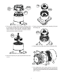
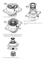
4. Place the brake housing (224) on the workbench and
place the spring locator in the housing. Refer to the
unit material list for the required number of springs
(225). Space the required number of springs evenly
around the outside diameter of the spring locator.
CAUTION
The number of steel discs, friction discs, and brake
springs is listed on the material list. SD40 gearboxes are
used in several applications with different brake requirements, so it is critical to reference the unit’s material list
for this information.
5. Install the spring pressure plate (227) on top of the
springs in the brake housing. The close fitting spring
pressure plate may be depressed at a slight angle to
lodge it into the brake housing which will hold the parts
in place while the brake housing is lowered onto the
motor adapter.
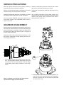
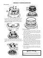
1. Begin assembly by placing the motor adapter on a
workbench with the motor mounting surface down. Install a new o-ring (230).
2. Refer to the gearbox material list for the number of
steel discs and friction discs needed. Lubricate the
friction discs with the gearbox oil. The brake stack will
alternate steel and friction discs ending with steel disc
on one end and a friction disc on the opposite end. Any
additional steel discs are the first discs put into the motor adapter. The brake stack is then installed in the
motor adapter beginning with a friction disc and alternating until the final steel disc is installed. Place the
spacer (229) on top of the top steel disc.
6. Apply petroleum jelly, grease, or hydraulic oil to the mating surfaces of the o-ring and seal on the motor adapter. Install the brake housing over the motor adapter
carefully to avoid damaging the seal and o-ring.
7. Install motor adapter capscrews and tighten each bolt
one turn at a time in a crossing pattern to keep motor
adapter level as springs are compressed. Torque to
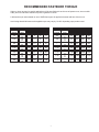
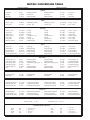
chart level; chart located on page 7.
3. Lubricate the brake piston u-cup seal (228) and the
motor adapter sealing surface with petroleum jelly or
hydraulic oil. Install the brake piston seal onto the motor support with the seal lip down.
BRAKE CYLINDER PRESSURE TEST
1. Connect a hydraulic hand pump with an accurate gauge
and shut-off valve to the brake release port of the brake
cylinder. Apply 500 psi to the brake. Close the shut-off
valve and let stand for five (5) minutes. If there is any
loss of pressure in five (5) minutes, the brake cylinder
should be disassembled for inspection of the sealing
surfaces and o-rings. (See the following step before releasing brake pressure.)
2. WHILE PRESSURE IS APPLIED AND THE BRAKE
IS RELEASED, install the brake hub assembly. Rotate
the clutch back and forth to align the outer race splines
with the brake disc splines. Release the pressure on
the brake cylinder and remove the brake hub and hand
pump. The brake assembly is now complete and ready
to be assembled with the main ring gear.
14