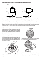
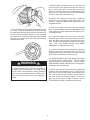
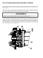
1
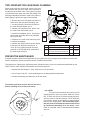
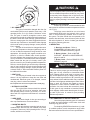
SERIES
PD12C
PD15B
PD17A
HYDRAULIC HOIST
INSTALLATION, MAINTENANCE, AND SERVICE MANUAL
LIT2103 R4
4-2010
PRINTED IN U.S.A.
1
Table of Contents
GENERAL SAFETY RECOMMENDATIONS ................................................................ 4
THEORY OF OPERATION ............................................................................................ 5
HOIST INSTALLATION.................................................................................................. 7
RECOMMENDED FASTENER TORQUE ..................................................................... 9
WIRE AND BRAIDED ROPE INSTALLATION .............................................................. 9
TWO SPEED MOTOR CASE DRAIN PLUMBING ...................................................... 10
PREVENTIVE MAINTENANCE................................................................................... 10
RECOMMENDED OIL CHANGE INFORMATION....................................................... 11
TROUBLE SHOOTING ............................................................................................... 12
HOIST DISASSEMBLY................................................................................................ 16
EXPLODED VIEW DRAWING AND PARTS KEY ..................................................18-19
PLANET CARRIER SERVICE ..................................................................................... 20
MOTOR SUPPORT – BRAKE CYLINDER SERVICE ................................................. 22
BRAKE CLUTCH SERVICE ........................................................................................ 26
HOIST ASSEMBLY ...................................................................................................... 28
BRAKE VALVE SERVICE............................................................................................ 32
REVERSING DIRECTION OF DRUM ROTATION ...................................................... 34
PD17A ROTATION INDICATION PROXIMITY SENSOR ............................................ 36
2
FOREWORD
Read this entire publication and retain it for future reference.
If you have any questions regarding your Braden Planetary Hoist or this publication, call the Braden Service Department at 1-918-251-8511, 08:00-1630 hours, CT, Monday through Friday.
The minimum service intervals specified are for operating hours of the prime mover.
The following service instructions have been prepared to provide assembly, disassembly and maintenance information for the BRADEN Model PD12C, PD15B and PD17A series hoist. It is suggested that before doing any work on
these units, all assembly and disassembly instructions should be read and understood.
Some pictures in this manual may show details or attachments that are different from your hoist. Also, some components have been removed for illustrative purposes. Illustrations and pictures in this manual are of a “typical” unit sold
through our distribution channels. Some hoists, particularly those sold directly to original equipment manufacturers
(OEM), may differ in appearance and options.
Whenever a question arises regarding your BRADEN HOIST, please contact BRADEN Service Department for the
latest available information.
Serial Numbers and Model Numbers are located to
the left hand side of the hydraulic motor, stamped
into the base. Always refer to the Serial Number and
Model Number when requesting information or service parts.
EXPLANATION OF MODEL NUMBER
PD
12
C
29
064 - 02 - U - L - 1
POWER
DRUM
MAX
RATING
DESIGN
SERIES
GEAR
RATIO
MOTOR
SIZE
PD
12
C
29
064
02
U
L
1
DRUM
OPTION
ROTATION
BASE
DESIGNATES POWER DRUM
DESIGNATES 12,000 LB. APPROXIMATE FIRST LAYER LINE PULL
DESIGNATES THE MODEL SERIES RELATING TO DESIGN CHANGES
DESIGNATES TOTAL GEAR REDUCTION (OTHER RATIOS INCLUDE 21, 41, 59, 34, ETC.)
DESIGNATES HYDRAULIC MOTOR DISPLACEMENT IN CU. IN/REV
(DECIMAL POINT ELIMINATED. EXAMPLE 064 = 6.4 CU IN/REV)
DESIGNATES THE DRUM OPTION (OTHER DRUMS INCLUDE 01, 04, 05, 23G, ETC.)
DESIGNATES UNDERWOUND CABLE DRUM - OPTIONAL
DESIGNATES LEFT HAND BASE - OPTIONAL, BLANK IS STANDARD RIGHT HAND BASE
PERMITS TESTING AND INSPECTION PER API 2C FOR OFFSHORE CRANES - OPTIONAL
3
OPTION
GENERAL SAFETY RECOMMENDATIONS
Safety and informational callouts used in this manual include:
!
! WARNING !
CAUTION !
CAUTION – This emblem is used to warn against
potential or unsafe practices which COULD result
in personal injury and product or property damage if
proper procedures are not followed.
WARNING – This emblem is used to warn against
hazards and unsafe practice which COULD result in
severe personal injury or death if proper procedures
are not followed.
Safety for operators and ground personnel is of prime concern. Always take the necessary precautions to ensure
safety to others as well as yourself. To ensure safety, the prime mover and hoist must be operated with care and
concern by the operator for the equipment and a thorough knowledge of the machine’s performance capabilities.
The following recommendations are offered as a general safety guide. Local rules and regulations will also apply.
1. Be certain equipment (boom, sheave blocks, pendants, etc.) is either lowered to the ground or
blocked securely before servicing, adjusting, or repairing hoist.
16. Do not use knots to secure or attach wire rope.
17. The BRADEN designed wire rope anchors are capable of supporting the rated load when installed
properly. For additional safety, ALWAYS maintain
a minimum of five (5) wraps of wire rope on the
drum.
2. Be sure personnel are clear of work area BEFORE
operating hoist.
3. Read all warning and caution tag information provided for safe operation and service of hoist.
18. Never attempt to clean, oil or perform any maintenance on a machine with the engine or prime mover
running, unless instructed to do so in this manual.
4. Inspect rigging and hoist at the beginning of each
work shift. Defects should be corrected immediately.
19. Never operate hoist controls unless you are properly positioned at the operators station and you are
sure personnel are clear of the work area.
5. Keep equipment in good operating condition. Perform
scheduled servicing and adjustments listed in the
“Preventive Maintenance” section of this manual.
20.Assure that personnel who are responsible for hand
signals are clearly visible and that the signals to be
used are thoroughly understood by everyone.
6. An equipment warm-up procedure is recommended
for all start-ups and essential at ambient temperatures below +40°F (4°C). Refer to “Warm-up Procedure” listed in the “Preventive Maintenance” section
of this manual.
21.Ground personnel should stay in view of the operator and clear of hoist drum. Do not allow ground personnel near hoist line under tension. A safe distance
of at least 1-1/2 times the length of the cable should
be maintained.
7. Operate hoist line speeds to match job conditions.
22. Do not exceed the maximum pressure, PSI (kPa),
or flow, GPM (LPM), stated in the hoist specifications.
8. Leather gloves should be used when handling wire
rope.
9. Never attempt to handle wire rope when the hook
end is not free. Keep all parts of body and clothing
clear of cable rollers, cable entry area of fairleads
and hoist drum.
23. Install guarding to prevent personnel from getting any part of body or clothing caught at a point
where the cable is wrapped onto the drum or drawn
through guide rollers.
10. When winding wire rope on the hoist drum, never
attempt to maintain tension by allowing wire rope to
slip through hands. Always use “Hand-Over-Hand”
technique.
24. “Deadman” controls, which automatically shut off
power to the hoist whenever the operator leaves his
station, should be installed whenever practicable.
11. Never use wire rope with broken strands. Replace
wire rope.
25. Never allow anyone to stand under a suspended
load.
12. Do not weld on any part of the hoist.
26. Avoid sudden “shock” loads or attempting to “jerk”
load free. This type of operation may cause heavy
loads, in excess of rated capacity, which may result
in failure of cable and hoist.
13.Use recommended hydraulic oil and gear lubricant.
14. Keep hydraulic system clean and free from contamination at all times.
15. Use correct anchor for wire rope and pocket in
drum.
4
THEORY OF OPERATION
DESCRIPTION OF HOIST
The hoist has four basic component parts:
The static brake system has three operating components:
1. Spring Applied, Multiple Friction Disc Static Brake
2. Overrunning Brake Clutch Assembly
3. Hydraulic Piston and Cylinder
1. Hoist base
2. Hydraulic motor and brake valve
3. Brake cylinder and motor support
4. Drum assembly
The drum assembly consists of three basic assemblies:
1. Drum with integral ring gear
2. Output planetary gear set
3. Primary planetary gear set
Figure 1
HOISTING
The hydraulic motor is bolted to the motor support which
in turn is bolted to the brake cylinder and the base. The
motor end of the drum, running on a ball bearing, is
supported by the brake cylinder. The other end of the
drum runs on a ball bearing on the support bolted to the
base. The ring gear for both planetary sets is machined
into the drum’s inside surface.
Static Brake
Motor
Brake Valve
To Tank
HOIST OPERATION
The hydraulic motor drives the sun gear of the primary
planetary gear set through the splined inner race of the
overrunning brake clutch. When driven by the sun gear,
the primary planet gears walk around the ring gear in
the drum and drive the primary planet carrier.
Pump
Control Valve
Low
Pressure
The primary planet carrier drives the output planet
sun gear which, in turn drives the output planet gears.
The output planet carrier is splined to the bearing support and cannot rotate. Therefore, as the output planet
gears are driven by the sun gear, they will drive the ring
gear/drum.
High
Pressure
Medium
Pressure
Figure 2
DUAL BRAKE SYSTEM - DESCRIPTION
LOWERING 1
The dual brake system consists of a dynamic brake
system and a static brake system.
The dynamic brake system has two operating components:
1. Brake valve assembly
2. Hydraulic motor
The brake valve is basically a counterbalance valve
with good metering characteristics. It contains a check
valve to allow free flow of oil to the motor in the hoisting direction and a pilot operated, spring-loaded spool
valve that blocks the flow of oil out of the motor when
the control valve is placed in neutral. When the control
valve is placed in the lowering position, the spool valve
remains closed until sufficient pilot pressure is applied
to the end of the spool to shift it against spring pressure and open a passage. After the spool valve cracks
open, the pilot pressure becomes flow-dependent and
modulates the spool valve opening which controls the
lowering speed. Refer to figures 1, 2, and 3.
Figures 1, 2, and 3.
Static Brake
Motor
Brake Valve
To Tank
Pump
Control Valve
Low
Pressure
5
Medium
Pressure
High
Pressure
determine the amount of oil that can flow through it and
the speed at which the load will be lowered. Increasing
the flow of oil to the----- motor will cause the pressure
to rise and the opening in the brake valve to enlarge,
speeding up the descent of the load. Decreasing this
flow causes the pressure to lower and the opening in
the brake valve to decrease thus slowing the descent
of the load.
Figure 3
LOWERING 2
Static Brake
Motor
Brake Valve
When the control valve is shifted to neutral, the pressure will drop and the brake valve will close, stopping
the load. The friction brake will engage and hold the
load after the brake valve has closed.
To Tank
When lowering a load very slowly for precise positioning, no oil flow actually occurs through the hoist motor.
The pressure will build up to a point where the brake will
release sufficiently to allow the load to rotate the motor
through its own internal leakage. This feature results in
a very slow speed and extremely accurate positioning.
Pump
Control Valve
Low
Pressure
Medium
Pressure
High
Pressure
The friction brake receives very little wear in the lowering operation. All of the heat generated by the lowering
and stopping of a load is absorbed by the hydraulic oil
where it can be readily dissipated.
The static brake is released by the brake valve pilot
pressure at a pressure lower than that required to open
the pilot operated spool valve. This sequence assures
that dynamic braking takes place in the brake valve and
that little, if any, heat is absorbed by the friction brake.
The friction brake is a load holding brake only and has
nothing to do with dynamic braking or rate of descent
of a load.
Figure 4
Sprag Cams
Static Friction Brake Applied
The overrunning brake clutch is splined to the primary
sun gear shaft between the motor and the primary sun
gear. It will allow this shaft to turn freely in the direction
to raise a load and lock up to force the brake discs to
turn with the shaft in the direction to lower a load. Refer
to figures 4 and 5.
The hydraulic cylinder, when pressurized, will release
the spring pressure on the brake discs, allowing the
brake discs to turn freely.
Permits free shaft rotation
while hoisting
Dual Brake System – Operation
When hoisting a load, the brake clutch which connects
the motor shaft to the primary sun gear, allows free rotation. The sprag cams lay over and permit the inner race
to turn free of the outer race. Figure 4. The friction brake
remains fully engaged. The hoist, in raising a load, is
not affected by any braking action. Figure 1.
Figure 5
Sprag Cams
Static Friction Brake Applied
When the lifting operation is stopped, the load attempts
to turn the primary sun gear in the opposite direction.
This reversed input causes the sprag cams to instantly
roll upward and firmly lock the shaft to the fully engaged
friction brake. Figure 5.
When the hoist is powered in reverse, to lower the load,
the motor cannot rotate until sufficient pilot pressure is
present to open the brake valve. Figures 2 & 3. The
friction brake within the hoist will completely release at
a pressure lower than that required to open the brake
valve. The extent to which the brake valve opens will
Load attempts to rotate shaft in opposite direction
Brake clutch locks sun gear shaft to friction brake
6
HOIST INSTALLATION
1. The hoist should be mounted with the centerline of
the drum in a horizontal position. The mounting plane
of the base may be rotated in any position around this
centerline.
HOIS
VENT PLUG
ABOVE CENTERLINE
T
CenterLine
4. The vent plug must always be located above the horizontal centerline. If the hoist is mounted on a pivoting
surface, be sure vent plug remains above the centerline
in all positions. If necessary, reposition bearing support
and vent plug as follows:
SIONS
BROKE
U.S.A.
4012
This hoist m
BRADEN Gearmatic
SERIAL NO.
er
76381
HOIS
A. Remove bearing support bolts.
B. Rotate bearing support until vent plug
is positioned correctly and bolt holes
are aligned.
C. Evenly tighten bolts to recommended
torque.
T
5. Hydraulic lines and components that operate the
hoist must be of sufficient size to assure minimum backpressure at the hoist motor ports. The hydraulic backpressure measured at the motor work ports must be
less than 100 PSI (690 kPa) at full operating flow. Backpressure in excess of 100 PSI (690 kPa) will shorten
motor shaft seal life and partially release the load holding brake. The standard hoist is supplied with the gear
motor internally drained and connected the drain bypass port on the Braden brake valve. If high back-pressures are encountered, the motor should be externally
drained directly to the reservoir and the “DRAIN” port
on the brake valve capped. All piston motors MUST be
drained directly to the reservoir. The piston motor case
drain port must NEVER be exposed to more than 42
PSI (290 kPa); shaft seal damage will occur.
WINCH DIVISIONS
BROKEN ARROW,OK.,74012
U.S.A.
This hoist must be maintained per
BRADEN Gearmatic Service Manual.
SERIAL NO.
76381
2. Because of the design of the mounting base, the direction of line pull should only be as shown in the above
illustration. Line pulls in any other direction must be approved by BRADEN Engineering.
3. When mounting the hoist, use all eight (8) mounting holes and grade 8 capscrews and nuts. Tighten to
recommended torque.
It is important that the hoist is mounted on a surface
that will not flex when in use, and cause binding of the
gear train. Binding in the gear train will result in accelerated wear and heat. Also, be sure the hoist is mounted
on a flat surface. If necessary, use shim stock to insure
the mounting surface is flat within 0.020 in. (0.5 mm).
Use stainless steel shim stock as required.
6. The hoist should be mounted perpendicular to an
imaginary line from the center of the drum to the first
sheave to insure even spooling. Make certain the fleet
angle does not exceed 1-1/2 degrees.
FLEET ANGLE
TO LOAD
OR
FIRST SHEAVE
A
1/2 O
1 1/2 O
MIN
MAX
B
A=B
7
HOIST ASSEMBLY
W/BRAKE VALVE
& STATIC BRAKE
WINCH ASSEMBLY
W/BRAKE VALVE
& STATIC BRAKE
BRAKE
VALVE
T
P
HOIST BRAKE
BRAKE
VALVE
BR
WINCH BRAKE
BR
A
DR
DR
CONTROL
VALVE
2-SPEED
SELECTOR
VALVE
CONTROL
VALVE
PUMP
PUMP
Oil having 150 to 330 SUS (30-60 cSt) viscosity at 104°F
(40°C) and viscosity index of 100 or greater will give
good results under normal temperature conditions. The
use of an oil having a high viscosity index will minimize
cold-start trouble and reduce the length of warm-up periods. A high viscosity index will minimize changes in
viscosity with corresponding changes in temperature.
! WARNING !
DO NOT use a control valve with any detents or
latching mechanism that would hold the control valve
in an actuated or running position when the operator
releases the control handle. Use of the wrong type
of control valve could lead to unintentional operation
of the hoist, which could result in property damage,
personal injury, or death.
Maximum cold weather start-up viscosity should not
exceed 5000 SUS (1000cSt) with a pour point at least
20°F (11°C) lower than the minimum temperature.
Under continuous operating conditions the temperature
of the oil at any point in the system must not exceed
180° (82°C). Optimum oil temperature is generally considered to be 120-140°F (49-60°C).
In general terms; for continuous operation at ambient
temperatures between 50 and 110°F (10 to 43°C) use
ISO 46; for continuous operation between 10 and 90°F
(-12 to 32°C) use ISO 32; for applications colder than
10°F (-12°C), contact the BRADEN Service Department. The use of multi-viscosity oils is generally not
recommended.
The directional control valve must be a three position,
four- way valve without detents and with a spring centered motor spool such that the valve returns to the
centered position whenever the handle is released, and
both work ports are open to tank (open center, open
port).
8. The hydraulic oil filter should have a 10 micron nominal rating and be full flow type and meet the requirements of the hydraulic pump manufacturer.
7. High quality hydraulic oil is essential for satisfactory
performance and long hydraulic system component
life.
8
RECOMMENDED FASTENER TORQUE
Higher or lower torques for special applications will be specified such as the use of spanner nuts, nuts on shaft
ends, jam nuts and where distortion of parts or gaskets is critical.
Lubricated torque values based on use of SAE 30wt engine oil applied to threads and face of bolt or nut.
Avoid using thread lubricants (such as anti-seize compound) as the applied torque may vary by 10 - 40%, depending upon the product used.
7RUTXH/%)71P
7RUTXH/%)71P
%ROW
'LDP
,QFKHV
7KUHDG
SHU
LQFK
%ROW
'LDP
,QFKHV
7KUHDG
SHU
LQFK
'U\
/XEHG
'U\
/XEHG
'U\
/XEHG
'U\
/XEHG
*UDGH
*UDGH
*UDGH
*UDGH
7RFRQYHUW/%)7WR.JPPXOWLSO\/%)7YDOXHE\
WIRE AND BRAIDED ROPE INSTALLATION
ANCHORING WIRE ROPE
ANCHORING BRAIDED ROPE
Early Style
Wire Rope
Anchor
Take the free end of the wire rope and insert it through
the small opening of the anchor pocket. Loop the wire
rope and push the free end about half of the way back
through the pocket. Install the wedge, then pull the slack
out of the wire rope. The wedge will slip into the pocket
and secure the wire rope into the drum. The early style
anchor wedge is designed to accommodate several different sizes of wire rope. You may anchor 7/16 and 1/2
in. (11 & 13 mm) wire rope by inserting the wedge, large
end first. Anchor 9/16 and 5/8 in. (14 & 16 mm) wire
rope by inserting the wedge, small end first.
A special wedge is used to anchor 1 and 1 1/8 in. (25
& 28 m) braided synthetic rope. The installation procedure is the same as for anchoring wire rope.
CORRECT INSTALLATION
INCORRECT INSTALLATION
Drive from
this side
Wedge not
fully Seated
Wedge and wire
rope fully seated
in pocket
Figure 7
Figure 9
Figure 8
9
Wedge pulled
too far through
anchor pocket
Figure 10
TWO SPEED MOTOR CASE DRAIN PLUMBING
Some hoists with two speed gear motors may have
been installed with the motor case drain connected to
the drain port of the brake valve. This system may result
in accelerated motor shaft seal wear and leakage. The
following modification should be made to the motor hydraulic piping to prevent this type of seal damage.
1
1. Remove the motor case drain hose from the
brake valve drain port and install plug, Item
1, into the valve port. Remove the hose from
the case drain port elbow, Item 4.
2. Install a new case drain hose, Item 2, onto
the motor case drain elbow, Item 4.
3. Install the tee adapter, Item 3, into the twospeed motor shift valve drain port (identified
by long end cap).
2
4. Install the new motor case drain hose, Item
2, onto the tee adapter.
3
5. Install a case drain hose for the tee directly
to the reservoir. Minimum hose size is –6,
3/8 in. (9.5 mm). Maximum drain line back
pressure is 100 PSI (690 kPa) measured at
the motor case drain port.
ITEM
DESCRIPTION
QTY
PART #
1
Plug, -4 ORB
1
25663
2
Hose, 17-in. OAL
(-4 JIC Fml Svl/-4 Hose/ 1/8 NPT ml)
1
13707
3
Tee -4 (ORB Branch -4 JIC Run)
1
29078
PREVENTIVE MAINTENANCE
A regular program of preventive maintenance for your planetary hoist is strongly recommended to minimize the
need for emergency servicing and promote safe, reliable hoist operation.
Field experience, supported by engineering tests, indicate the three (3) service procedures listed below are the
MOST critical to safe, reliable hoist operation and must be observed.
• Regular Gear Oil Changes – every 1000 hours or six (6) months
• Use of Proper Gear Oil – recommended type for prevailing ambient temperature
• Periodic disassembly and inspection of all wear items.
The following minimum service intervals are specified for operating hours of the prime mover.
1. OIL LEVEL
The gear oil level should be checked every 500
operating hours or three (3) months, whichever occurs
first. To check the oil level, remove the large plug located in the center of the drum support. The oil should be
level with the bottom of this opening or approximately
half-way up in a sight glass. This is extremely important due to the accelerated wear that can be caused
by insufficient lubricating oil in the hoist. If additional oil in needed, refer to “Recommended Planetary
Gear Oil”.
10
! WARNING !
Failure to properly warm up the hoist, particularly under low ambient temperature conditions, may result
in temporary brake slippage due to high back pressures attempting to release the brake, which could
result in property damage, severe personal injury or
death.
7. WARM-UP PROCEDURES
A warm-up procedure is recommended at each
start-up and is essential at ambient temperatures below
+40°F (4°C).
The prime mover should be run at its lowest
recommended RPM with the hydraulic hoist control
valve in neutral allowing sufficient time to warm up
the system. The hoist should then be operated at low
speeds, raise and lower, several times to prime all lines
with warm hydraulic oil, and to circulate gear lubricant
through the planetary gear sets.
2. OIL CHANGE
The gear oil should be changed after the first
one hundred (100) hours of operation, then every 1,000
operating hours or six (6) months, whichever occurs
first. The gear oil must be changed to remove wear
particles that impede the reliable and safe operation of
the brake clutch and erode bearings, gears and seals.
Failure to change gear oil at these suggested minimum
intervals may contribute to intermittent brake slippage
which could result in property damage, severe personal
injury or death.
The gear oil should also be changed whenever
the ambient temperature changes significantly and an
oil from a different temperature range would be more
appropriate. Oil viscosity with regard to ambient temperature is critical to reliable brake clutch operation.
Our tests indicate that excessively heavy or thick gear
oil may contribute to intermittent brake clutch slippage.
Make certain that the gear oil viscosity used in your
hoist is correct for your prevailing ambient temperature.
Failure to use the proper type and viscosity of planetary
gear oil may contribute to brake clutch slippage which
could result in property damage, severe personal injury
or death. Refer to “Recommended Planetary Gear Oil”
for additional information.
8. INSPECTION
A. Bearings and Gears – Refer to
DISASSEMBLY OF Hoist, page 15; and
PLANET CARRIER SERVICE, page 20.
B. Brake Cylinder – Refer to MOTOR
SUPPORT – BRAKE CYLINDER SERVICE,
pages 22 and 23.
C. Brake Clutch – Refer to BRAKE CLUTCH
SERVICE, page 26.
! WARNING !
Failure to use the proper type and viscosity of planetary gear oil may contribute to intermittent brake
clutch slippage which could result in property damage, severe personal injury or death. Some gear lubricants contain large amounts of EP (extreme pressure) and anti-friction additives which may contribute
to brake clutch slippage and damage to brake friction
discs or seals. Oil viscosity with regard to ambient
temperature is also critical to reliable brake clutch
operation. Our tests indicate that excessively heavy
or thick gear oil may contribute to intermittent brake
clutch slippage. Make certain that the gear oil viscosity used in your hoist is correct for your prevailing
ambient temperature.
3. VENT PLUG
The vent plug is located in the drum support as
shown. It is very important to keep this vent clean and
unobstructed. Whenever gear oil is changed, remove
vent plug, clean in solvent and reinstall.
Do not paint over the vent or replace with a solid plug.
4. HYDRAULIC SYSTEM
The original filter element should be replaced
after the first fifty (50) hours of operation, then every
500 operating hours or three (3) months, or in accordance with the equipment manufacturer’s recommendations.
5. WIRE ROPE
Inspect entire length of wire rope according to
wire rope manufacturers recommendations.
9. RECOMMENDED PLANETARY GEAR OIL
Use of the proper planetary gear oil is essential
to reliable and safe operation of the brake clutch and
obtaining long gear train life.
6. MOUNTING BOLTS
Tighten all hoist base mounting bolts to recommended torque after the first one hundred (100) hours
of operation, then every 1000 operating hours or six (6)
months, whichever occurs first.
For simplicity, BRADEN has listed one (1) readily available product in each temperature range which
has been tested and found to meet our specifications.
11
RECOMMENDED PLANETARY GEAR OIL
PREVAILING AMBIENT TEMPERATURE
oF
-40
-30
-20
-10
0
10
20
30
40
50
60
70
80
90
100
110
120
130 oF
MOBILGEAR 600 XP 220 OR EQUIVALENT
AGMA 5 EP, ISO VG 220
MOBILGEAR 600 XP 150 OR EQUIVALENT
AGMA 4 EP, ISO VG 150
MOBILGEAR SHC 150
SYNTHETIC OR EQUIVALENT
oC
-40
i
-30
-20
-10
0
10
20
30
40
50
oC
NOTE: SHADED TEMPERATURE RANGE IN THE CHART ABOVE NOT RECOMMENDED FOR SEVERE APPLICATIONS SUCH AS: OFFSHORE
CRANES, SUSTAINED FAST DUTY CYCLES OR FREQUENT LIFTING.
Planetary hoists are factory filled with Mobilgear 600 XP 150, or equivalent. Consult your oil supplier for other equivalent
oils if required.
Shell
Chevron
Texaco
Mobilgear 600 XP 150
Mobil
Omala 150
Gear Compounds EP 150
Meropa 150
Mobilgear 600 XP 220
Omala 220
Gear Compounds EP 220
Meropa 220
OIL CAPACITIES:
NOTE: Capacities are approximate. Refer to “Oil
Level” earlier in this section
(PD12C/PD15B) 01, 02 & 22 DRUM - 6 PINTS (2.8 L)
(PD12C/PD15B) 04, 05 & 23G DRUM - 7 PINTS (3.3 L)
(PD17A) - 14 PINTS (6.6 L)
TROUBLESHOOTING
! WARNING !
If a hoist ever exhibits any sign of erratic operation, or load control difficulties (i.e. load creeping or chattering)
appropriate troubleshooting tests and repairs should be performed immediately. Continued operation in this
manner may result in property damage, serious personal injury or death.
TROUBLE
PROBABLE CAUSE
REMEDY
1. The problem could be a plugged
or loose pilot orifice. The pilot orifice is a small pipe plug with a hole
drilled through it, located behind the
pilot port fitting on the brake valve.
If it becomes plugged, it will prevent
the pilot pressure, from the manifold, from opening the brake valve.
If it becomes loose, it will allow an
unregulated amount of oil in to operate the brake valve which cause
erratic brake valve operation.
Remove the pilot hose and fitting
from the brake valve, then use a
5/32 inch Allen wrench to remove
the pilot orifice. The diameter of the
orifice is approximately .020 inches.
Clean and install the pilot orifice
tightly in the brake valve.
2. The friction brake may not be
releasing as a result of a defective
brake cylinder seal.
Check brake cylinder seal as follows:
A
The hoist will not lower the load or
not lower the load smoothly.
NOTE: If the brake cylinder seal
is defective you will usually find oil
leaking from the hoist vent plug.
A. Disconnect the swivel tee from
the brake release port. Connect a
hand pump with accurate 0-2000
psi gauge and shut-off valve to the
–4 J.I.C. fitting in the brake release
port.
12
TROUBLE
PROBABLE CAUSE
REMEDY
A
The hoist will not lower the load or
not lower the load smoothly.
1. Friction brake will not release as
a result of damaged brake discs.
A. Apply 1000 PSI (6,900 kPa) to
the brake. Close shut-off valve and
let stand for five (5) minutes.
B. If there is any loss of pressure
in five (5) minutes, the brake cylinder should be disassembled for inspection of the sealing surfaces and
replacement of the seals. Refer to
“Motor Support-Brake Cylinder Service”.
Disassemble brake to inspect brake
discs. Check stack-up height as
described in “Motor Support-Brake
Cylinder Service”.
B
Oil leaks from vent plug.
1. Same as A2.
Same as A2.
2. Motor seal may be defective as
a result of high system back pressure or contaminated oil.
System back pressure must not exceed 150 PSI (1,035 kPa). Inspect
hydraulic system for a restriction in
the return line from the control valve
to the reservoir. Be sure control
valve and plumbing is properly sized
to hoist motor.
Oil analysis may indicate contamination has worn motor shaft and
seal. Thoroughly flush entire hydraulic system and install new filters
and oil. Install new motor seal.
C
The brake will not hold a load with
the control lever in neutral.
1. Excessive system back pressure The same as Remedy 2 of Trouble
B2.
acting on the brake release port.
2. Friction brake will not hold due to Same as Remedy 3 of Trouble A3.
worn or damaged brake discs.
3. Brake clutch is slipping.
Improper planetary gear oil may
cause the brake clutch to slip. Drain
old gear oil and flush hoist with solvent. Thoroughly drain solvent and
refill hoist with recommended planetary gear oil listed in “Preventive
Maintenance”.
Brake clutch may be damaged or
worn. Disassemble and inspect
brake clutch as described in “Brake
Clutch Service”.
13
TROUBLE
PROBABLE CAUSE
REMEDY
D
The hoist will not hoist the rated
load.
1. The hoist may be mounted on
an uneven or flexible surface which
causes distortion of the hoist base
and binding of the gear train. Binding in the gear train will absorb
horsepower needed to hoist the
rated load and cause heat.
Reinforce mounting surface.
2. System relief valve may be set
too low. Relief valve needs adjustment or repair.
Check relief pressure as follows:
If necessary, use shim stock to level
hoist. Refer to “Hoist Installation”.
First loosen, then evenly retighten
all hoist mounting bolts to recommended torque.
A. Install an accurate 0-4000 psi
(27,580 kPa) gauge into the inlet
port of the brake valve.
B. Apply a stall pull load on the hoist
while monitoring pressure.
C. Compare gauge reading to hoist
specifications. Adjust relief valve as
required.
NOTE: If pressure does not increase in proportion to adjustment,
relief valve may be contaminated or
worn out. In either case, the relief
valve may require disassembly or
replacement.
3. Be certain hydraulic system temperature is not more than 180 degrees F. Excessive hydraulic oil
temperatures increase motor internal leakage and reduce motor performance.
Same as remedies for Trouble D1 &
D2.
4. Hoist line pull rating is based on
1st layer of wire rope.
Refer to hoist performance charts
for additional information.
5. Rigging and sheaves not operating efficiently.
Perform rigging service as recommended by crane manufacturer.
1. Same as D1.
Same as remedies for Trouble D1.
Same as remedies for Trouble E2.
E
The hoist runs hot.
2. Be certain that the hydraulic system temperature is not more than
180 degrees F. Excessive hydraulic oil temperatures may be caused
by:
A. Plugged heat exchanger.
Thoroughly clean exterior and flush
interior.
B. Too low or too high oil level in hydraulic reservoir.
Fill/drain to proper level.
C. Same as D2.
Same remedies as D2
14
TROUBLE
E
The hoist runs hot.
PROBABLE CAUSE
D. Hydraulic pump not operating
efficiently.
REMEDY
Same as remedies for Trouble D2.
Prime mover low on horsepower or
R.P.M. Tune/adjust prime mover.
Check suction line for damage.
If pump is belt driven, belts are slipping. Replace/tighten belts.
Pump worn. Replace pump.
3. Excessively worn or damaged
internal hoist parts.
Disassemble hoist to inspect/replace worn parts.
1. Same as D2.
Same as remedies for Trouble D2.
2. Hydraulic oil flow to motor may
be too low.
Same as remedies for Trouble E2.
3. Controls being operated too
quickly.
Conduct operator training as required.
1. The hoist may be mounted too
close to the main sheave, causing the fleet angle to be more than
1-1/2 degrees.
Check mounting distance and fleet
angle. Reposition hoist as required.
2. The hoist may not be mounted
perpendicular to an imaginary line
between the center of the cable
drum and the first sheave.
Refer to “Hoist Installation”.
3. Could possibly be using the
wrong lay rope. There is a distinct
advantage in applying rope of the
proper direction of lay. When the
load is slacked off, the several coils
on the drum will stay closer together and maintain an even layer.
If rope of improper lay is used, the
coils will spread apart each time
the load is removed. Then, when
winding is resumed, the rope has a
tendency to criss-cross and overlap
on the drum. The result is apt to be
a flattened and crushed rope.
Consult wire rope manufacturer for
recommendation of wire rope that
best suits your application.
4. The hoist may have been overloaded, causing permanent set in
the wire rope.
Replace wire rope and conduct
operator/rigger training as required.
F
Hoist “chatters” while raising rated
load.
G
The wire rope does not spool
smoothly on the drum.
15
DISASSEMBLY OF HOIST
SERVICE PRECAUTIONS
•
Before any part is removed from the hoist, all service instructions should be read and understood.
•
Work in a clean, dust free area as cleanliness is of utmost importance when servicing hydraulic equipment.
•
Inspect all replacement parts, prior to installation, to detect any damage which might have occurred in shipment.
•
Use only genuine BRADEN replacement parts for optimum results. Never reuse expendable parts such as oil
seals and O-rings.
•
Inspect all machined surfaces for excessive wear or damage . . . before reassembly operations are begun.
•
Lubricate all O-rings and oil seals with gear oil prior to installation.
•
Use a sealing compound on the outside surface of oil seals and a light coat of thread sealing compound on
pipe threads. Avoid getting thread compound inside parts or passages which conduct oil.
•
Thoroughly clean all parts in a good grade of non-flammable safety solvent. Wear protective clothing as required.
After troubleshooting the hoist and its hydraulic system as covered in the “Troubleshooting” section, and the problem is determined to be in the hoist, use the following procedure to disassemble the hoist.
1. Remove the wire rope from the cable drum and align
the drain hole in the drum with a hole in the support
side plate before removing the hoses and mounting
bolts. After the hoist is removed from its mounting, thoroughly clean the outside surfaces. To drain the oil, install a short piece of 1 inch pipe in the larger threads of
the drain hole. If necessary, insert a bar into the anchor
pocket and manually rotate the drum in the direction to
hoist a load until the drain holes are aligned.
3. Begin disassembly by removing the oil level plug or
sight glass and standing the hoist on the bearing support
end. Tag and remove the hydraulic hoses that connect
the brake valve and manifold to the brake cylinder.
4. Remove the capscrews securing the motor, and lift
the motor off the hoist. Remove and discard the O-ring
installed on the pilot of the motor.
2. Use a 5/16 inch Allen wrench to remove the drain
plug through the pipe.
5. Tag and remove the hoses and fittings from the brake
cylinder release port.
16
9. Using two heel type pry bars placed between the primary planet carrier and the drum closure, pry upward to
remove the drum closure. Remove and discard the Oring from the outside of the drum closure. Some drum
closures have 3/8-16 tapped lifting eye holes that may
be used in place of the heel bars
6. Remove the brake clutch assembly from the motor
support. Refer to “Brake Clutch Service” for additional
information.
10. Remove the seal and bearing from inside of closure.
7. Remove the motor support capscrews and install two
(2) capscrews and a short piece of chain into the motor
mounting bolt holes. Using the chain as a handle, lift
the motor support out of the brake cylinder being careful to avoid damaging the sealing surfaces. Remove
and discard the O-ring and back-up ring from the motor
support. Refer to “Motor Support-Brake Cylinder Service” for additional information. Note the location of the
brake release port in relation to hoist prior to removing
the brake cylinder
11. Remove the primary sun gear and thrust washer
from the primary planet carrier.
8. Remove the brake cylinder capscrews and install two
(2) capscrews and a short piece of chain into the motor support mounting bolt holes. Using the chain as a
handle, lift the brake cylinder out of the drum and base,
being careful to avoid damaging the sealing or bearing
surfaces. Refer to “Motor Support-Brake Cylinder Service” for additional information.
12. Remove the primary planet carrier from the drum.
Refer to “Planet Carrier Service” for additional information.
For PD15B hoists, the drum closure cannot be removed through the opening in the base. If your hoist
has a one-piece cast base, remove the bearing support, as described in step 15, and remove the drum
from the base. Then proceed with steps 9 thru 14. If
your hoist has a three piece base, remove the motor
end side plate and continue with step 9.
17
15. Stand hoist on motor end with bearing support up;
then remove eight (8) bearing support capscrews and
bearing support being careful to avoid damaging the
sealing or bearing surfaces.
16. Slide drum out of base onto a work bench and remove seal and bearing from support end.
17. Thoroughly clean and inspect drum and base.
Check ring gear (machined into inside surface of drum)
teeth for nicks, spalling or excessive wear. Replace if
wear is greater than 0.015 in. (0.4 mm) when compared
to unworn area of teeth.
13. Remove the output sun gear and thrust washer from
the output planet carrier.
14. Remove the output planet carrier from the drum.
Refer to “Planet Carrier Service” for additional information.
BRADEN PD12C/15B17A COMPONENTS
ITEM
1
2
3
4
5
6
7
10
11
12
13
14
15
16
17
18
19
20
21
22
23
24
25
26
27
28
29
30
31
32
33
34
35
36
37
38
40
41
QTY
1
1
1
1
12
7
8
1
3
3
3
6
6
1
3
3
6
3
6
1
1
1
1
2
1
1
1
1
1
1
1
1
1
2
1
1
16
24
DESCRIPTION
Brake Cylinder
Piston Seal
Pressure Plate
Piston Back-up Ring
Spring
Friction Disc
Brake Disc
Primary Planet Carrier
Primary Planet Gear
Primary Planet Gear Shaft
Roller Bearing
Thrust Washer
Spirol Pin
Output Planet Carrier
Output Planet Gear
Output Planet Gear Shaft
Roller Bearing
Bearing Spacer
Thrust Washer
One-Piece Base
Bearing Support
Cable Drum
Cable Drum Closure
Ball Bearing
Oil Seal
O-ring
Oil Seal
Retaining Ring
Thrust Washer
Motor Support
O-Ring
Output Sun Gear
Primary Sun Gear
Spacer
Primary Sun Gear
Output Thrust Plate
Capscrew
Lockwasher
ITEM
42
43
44
45
46
47
48
49
50
51
52
53
54
55
57
58
59
60
61
62
63
64
65
66
67
68
69
70
72
90
91
92
93
94
95
96
97
99
18
QTY
4
1
1
1
1
1
1
1
1
2
2
2
1
1
1
1
2
4
4
1
1
2
1
1
1
1
1
4
1
1
1
1
16
16
1\2
2\4
2\4
1
DESCRIPTION
Capscrew
Thrust Washer
Plug- Hex Head
Plug- Flush
Vent Plug
O-Ring
Back-up Ring
Brake Race- Outer
Brake Race- Inner
Sprag Bushing
Sprag Bushing Retainer
Retaining Ring
Sprage Clutch
Retaining Ring
Cable Clamp
Manifold
O-ring
Capscrew
Capscrew
Brake Valve
Hose Assembly
Hose Assembly 12-inch
Adapter- straight
Elbow
swivel tee
elbow
Reducer elbow
Capscrew
Hydraulic Motor
Base Plate
Side Plate (bearing support end)
Side Plate (motor end)
Capscrew (special)
Washer
Tie Bar
Capscrew
Lockwasher
Spring Spacer
PD17A hoists use an
internal retaining ring (item
16, not shown) to hold item
38 into the output planet
carrier
PD17A
hoists
use only
1 each of
items 52
and 53
due to the
shoulder
on item 50.
(shoulder
is toward
motor)
Retaining
ring (item 30)
is not used
on PD17A
hoists
26
63
61
29
64
MOTOR
CASE
DRAIN
EL
EA
SE
68
ER
62
59
BR
AK
HOIST
70
69
72
41
To Item 1
65
66
64
67
59
58
92
97
96
19
60
LOWER
PLANET CARRIER SERVICE
OUTPUT PLANET CARRIER
DISASSEMBLY
3. Now you can remove the planet shafts, bearings,
spacer, thrust washers and gears. Thoroughly clean all
parts and inspect for damage and wear. The bearing
rollers should not exhibit any irregularities. If the rollers show any sign of spalling, corrosion, discoloration,
material displacement or abnormal wear, the bearing
should be replaced. Likewise, the cage should be inspected for unusual wear or deformation, particularly
the cage bars. If there is any damage that will impair
the cage’s ability to separate, retain and guide the rollers properly, the bearing should be replaced. The thrust
washer contact areas should be free from any surface
irregularities that may cause abrasions or friction. The
gears and shafts should be inspected for abnormal
wear or pitting. Replace if necessary.
1. Remove the planet gears by driving the roll pins into
the center of the planet shafts.
ASSEMBLY
2. Use a punch to drive the roll pins from the planet
shafts. Do not reuse the roll pins.
1. Place the output planet carrier on workbench with
splined coupling side down. Install output thrust plate in
center of carrier.
!
CAUTION !
PD17A hoists have an internal retaining ring to hold
the thrust plate into the carrier. This retaining ring
MUST be properly installed and fully seated before
the planet gears are installed.
20
PRIMARY PLANET CARRIER
1.To service the primary planet carrier, the steps are the
same as for the output carrier except there is only one
bearing for each gear and no bearing spacer.
2. Insert two (2) bearings and a bearing spacer into a
gear with the spacer between the bearings. Place a
thrust washer on each side of the gear and position in
a carrier opening. Slide the shaft through the carrier,
thrust washer, bearing-gear sub-assembly and remaining thrust washer. Be careful to avoid damaging thrust
washers when installing planet shafts.
3. Carefully align the pin hole in the carrier with the hole
in the planet gear shaft and drive the roll pin into place.
Always use NEW roll pins. When properly positioned,
50% of the roll pin will engage the planet gear shaft and
50% will remain in the planet carrier.
4. Note that the roll pin is slightly recessed in the carrier
when properly installed. With a center punch, stake
the carrier next to the pin hole as shown. This will distort the hole so the pin will not back out. Repeat these
steps for each of the three planet gears.
21
MOTOR SUPPORT-BRAKE CYLINDER SERVICE
NOTE: Starting mid-year 1996, Braden changed the
steel brake separator discs from a splined tooth design
to a lobed design. This required a change to the motor
support and brake cylinder and the addition of a spring
spacer. A hoist with the lobed discs can be identified
by a machined groove on the outside diameter of the
motor support. When replacing steel brake discs, the
motor support or brake cylinder, care must be taken to
properly identify the correct parts. Splined discs will remain available as spare parts.
New lobed steel brake separator plates and motor support. Note groove on outside diameter of motor support.
Although most photos in this section show splined discs,
all procedures are the same except where specifically
noted.
3.Remove the brake springs.
CLEAN AND INSPECT
DISASSEMBLY
1. After removing the motor support and brake clutch
assembly, continue brake cylinder disassembly by removing the spacers, friction brake discs and steel brake
discs.
1. Thoroughly clean and inspect all parts at this time.
Check brake piston sealing surfaces on brake cylinder
and motor support. Be sure brake release port is free
of contamination.
2. Remove the piston back-up ring and pressure
plate.
2. Check oil seal and bearing surfaces on brake cylinder for damage or wear.
22
!
ASSEMBLY
CAUTION !
Failure to replace brake springs as a set may result
in uneven brake application pressure and repeated
brake spring failure.
1. Begin assembly by placing motor support on workbench with motor mounting surface down. Install new
O-ring and back-up ring as shown.
3. Place friction brake disc on flat surface and check for
distortion with a straight edge. Friction material should
appear even across entire surface with groove pattern
visible. Replace friction disc if splines are worn to a
point, disc is distorted, friction material is worn unevenly, or groove pattern is worn away.
4. Place steel brake disc on flat surface and check for
distortion with a straight edge. Check surface for signs
of material transfer or heat. Replace steel disc if splines
are worn to a point, disc is distorted or heat discolored.
2. Install a brake spacer into the motor support. (NOT
REQUIRED WITH LOBED DISCS.)
5. Check brake spring free length; minimum free length
is 1 3/16 in. (30.2 mm). Check springs for any sign of
cracking or failure. If a brake spring must be replaced for
any reason, then ALL brake springs must be replaced.
3. Insert first, a steel brake disc against the spacer followed by a friction brake disc then alternate steel and
friction discs until seven (7) friction and eight (8) steel
discs have been installed. Finish with a steel brake
disc on top.
NOTE: It is a good practice to pre-lubricate the discs in
hydraulic oil prior to assembly.
23
4. Install the remaining brake spacer on top of the last
steel brake disc. (This is the only spacer used with
lobed discs.)
OLDER STYLE BRAKE CYLINDER
7.Install brake springs into brake cylinder
5. To check brake stack height, place pressure plate on
top of brake spacer. Hold pressure plate down firmly by
hand and measure clearance in three places between
motor support and pressure plate. Average gap must
measure between .153 in. (4 mm) maximum and .080
in. (2 mm) minimum. If the gap exceeds the maximum
limit, there are too many brake discs in stack-up or the
discs are distorted. If the gap is less than the minimum,
there are too few discs in stack-up or the discs are worn
out. When stack height is correct, remove pressure
plate and continue assembly.
NEW STYLE BRAKE CYLINDER
7A. When using the new style brake cylinder without
milled spring pockets, install the spring spacer, then the
brake springs.
! WARNING !
Always use the molded spring spacer with the new
brake cylinder. The brake springs must be properly
positioned by the spring spacer. Failure to install
the spring spacer may allow the springs to contact
each other and become damaged. This could result
in loss of load control, property damage, injury or
death.
8. Install pressure plate into brake cylinder followed
by the piston back-up ring. The close-fitting piston
back-up ring may be depressed slightly to one side
to lodge the back-up ring in the brake cylinder bore
and temporarily hold the pressure plate and springs
in place while you lower the brake cylinder over the
motor support.
6. Lubricate the brake piston seal and motor support
sealing surface with petroleum jelly or hydraulic oil. Install new piston seal to motor support, seal lip down.
24
9. Apply petroleum jelly to the entire sealing surface
of the brake cylinder and to the piston seal. Install the
brake cylinder over the motor support being careful to
avoid damaging the piston seal or motor support O-ring.
(A press may be necessary to avoid cocking the brake
cylinder during installation.)
2. WHILE PRESSURE IS APPLIED AND THE BRAKE
RELEASED, install the brake clutch assembly in the
brake pack, short end of the inner race toward motor.
Turn the clutch back and forth as you align the outer
race splines with the brake disc splines.
3. Release the pressure on the brake cylinder then remove the brake clutch assembly. The brake cylinder
assembly is now complete and ready to be installed in
the hoist.
10. Install motor support capscrews and evenly tighten
to recommended torque.
BRAKE CYLINDER PRESSURE TEST
1. Install the –4 J.I.C. fitting into the brake release
port. Connect a hand pump with accurate 0-2000 psi
(0-13,800 kPa) gauge and shut-off valve to this fitting.
Apply 1000 psi (6,900 kPa) to the brake. Close shut-off
valve and let stand for five (5) minutes. If there is any
loss of pressure in five (5) minutes, the brake cylinder
should be disassembled for inspection of the sealing
surfaces and brake piston.
25
BRAKE CLUTCH SERVICE
DISASSEMBLY
1. Remove the snap ring and sprag bushing retainer
from one end only.
4. Next, slide the sprag clutch out, inspect the sprag
clutch closely for abnormal wear, cracks, pitting or corrosion. Check small clips for breakage or bright spots;
the signs of excessive wear. Unless the outer race or
remaining sprag bushing is damaged or shows excessive wear, there is no need for further disassembly.
If disassembly is necessary, remove the bushing according to the procedure covered in Step No. three (3).
All brake clutch assembly parts should be thoroughly
cleaned and inspected before assembly.
NOTE: The brake clutch on PD17A hoists use a
stepped inner race, which eliminates one retaining ring
and bushing retainer. The larger end of the inner race
is toward the motor.
! WARNING !
The polished surfaces of the races and sprag cams
must be perfectly smooth to insure positive engagement of the clutch. The slightest defect may reduce
brake clutch effectiveness, which may lead to loss of
load control and result in property damage, personal
injury or death. It is generally recommended to replace the entire brake clutch assembly if any component is defective.
2. Pull the inner race out. Examine the race for scoring,
wear or indentations caused by the sprag cams.
ASSEMBLY
1. Press a sprag bushing into the outer race, using a
mechanical or hydraulic press. A flat plate of approximately the same diameter as the bushing flange outside diameter should be placed between the press and
bushing during assembly to protect the bushing. Be
certain the bushing flange is against the shoulder in the
outer race.
3. Use a screwdriver and mallet to remove the sprag
bushing from one end of the outer race. There are four
special cut-outs in the bushing for this purpose. Be
careful not to damage the bushing inside surface. If
a bushing’s inside surface is damaged or shows wear,
replace it.
26
6. Turn the assembly over with the snap ring down. Install the second retainer and snap ring. Make certain
the snap ring is seated in the groove properly.
2. Turn the assembly over and install the sprag clutch in
the bore of the outer race.
3. Press the remaining bushing into the race. Again,
make sure the bushing is against the shoulder.
7. This is a completed brake clutch assembly.
4. Next, install a sprag bushing retainer, then a snap
ring on the inner race. Be sure the snap ring is seated
in the snap ring groove. NOT necessary on PD17A due
to stepped design.
! WARNING !
Be certain the snap ring is seated in the groove in
the splined bore of the inner race. This snap ring will
keep the brake clutch assembly correctly positioned
in the center of the friction brake pack. Binding of the
brake or brake failure may occur if this snap ring is
omitted.
5. Slide the inner race through the bushings and sprag
clutch (the race will have to be rotated in the freewheeling direction to start it through the sprag clutch).
If the inner race will not go through the bushings, the
bushings have probably been damaged and should be
replaced.
27
HOIST ASSEMBLY
NOTE: PD15B HOISTS ONLY
The drum closure will not fit through the opening in the base. For hoists with a three piece base, first assemble the
bearing support side plate (91) to the base plate (90). Go to step 1 and follow the assembly procedure. Install the
motor end side plate and tie bar(s) after installing the drum closure in step 10.
For hoists with a one piece cast base, use the following assembly procedure. With the drum horizontal, install the
output planet carrier assembly, output sun gear (34), thrust washer (43), primary planet carrier assembly, thrust
washer (31) and drum closure. (Apply a light coat of grease to the thrust washer to hold them in position.) Position
the drum in the base and install the bearing support. (Refer to step 3 for two caution statements.) You may have to
rotate the bearing support or planet gears to engage the bearing support with the output planet carrier. Install and
hand tighten the bearing support capscrews. Stand hoist on bearing support end and visually check to verify the
primary thrust plate is properly positioned. (Refer to caution and drawings in step 16.) Install the primary sun gear
and proceed to step 11 to complete hoist assembly. Tighten bearing support capscrews to recommended torque
after motor is installed.
!
CAUTION !
Hoists with a three piece fabricated base use special shoulder capscrews to fasten side plates to the
base plate. DO NOT use standard capscrews in their
place.
PD12C, PD15B, PD17A
!
CAUTION !
Make certain the snap ring is installed on the bearing
support. This snap ring will keep the output planet
carrier correctly positioned in the hoist. Gear train
damage may occur if this snap ring is omitted.
1. Place hoist base on side with bearing support end
up.
2. Install a new bearing in the drum if replacement is
necessary. Apply a non-hardening sealant on the outside diameter of the new seal. Install the spring side of
the seal next to the bearing, then press into the drum,
using a flat plate to avoid distortion. Be sure drain plug
is installed securely.
3. Center the drum in the opening of the base. Lubricate the bearing support with petroleum jelly or gear oil
and install in base and drum.
28
!
CAUTION !
Be sure the vent plug is located above the horizontal
centerline for the intended application. Oil leakage
may occur if vent is positioned incorrectly.
4. Tighten the bearing support capscrews to the recommended torque.
8. Install the primary planet carrier, meshing the planet
gears with the ring gear and the planet housing with the
output sun gear.
5. Stand hoist on bearing support end. Install the output
sun gear and thrust washer into output planet carrier.
9. Install a new bearing in the drum closure as required.
Use sealant on the outside surface of the oil seal. Install with spring side of the seal toward bearing, using a
flat plate to avoid distortion.
6. Install the output planet carrier into the drum while
meshing the planet gears with the ring gear and the
planet housing with the bearing support.
Install a new O-ring in the groove on the O.D. of the
drum closure.
7. Install the primary sun gear and thrust washer into
the primary planet carrier.
10. Lubricate the O-ring and drum opening with petroleum jelly or gear oil and install the drum closure into
the drum.
29
11. Lubricate the pilot, oil seal and bearing surfaces of
the brake cylinder and carefully install brake cylinder
into base and drum. Locate the brake release port toward the lower rear corner of the base. Tighten brake
cylinder capscrews to recommended torque.
13. If the brake discs are misaligned, preventing the
installation of the clutch, then with a hand pump, apply 750-1000 psi to the brake release port. The brake
discs will move freely with the brake released, permitting alignment of the discs, brake clutch and input sun
gear.
12. Install the brake clutch assembly with the short end
of the inner race toward motor.
14. Install the hoses and fittings to the brake cylinder
release port.
When installed correctly, the inner race should turn freely in the opposite direction the drum turns to pull wire
rope in. An easy way to check the rotation is to hold the
outer race in one hand, and rotate the inner race.
15. Install a new O-ring on the motor pilot then lubricate
with petroleum jelly or gear oil.
NOTE: The following caution DOES NOT apply to
PD17A hoists. Proceed to step 16.
If the clutch free wheels in the wrong direction, disassemble the clutch and reverse the inner race. Refer to
“Brake Clutch Service” for additional information.
!
CAUTION !
Care must be taken to assure the primary thrust plate
remains properly located in its counterbore when the
motor is installed for the first time, or is being reinstalled on the hoist. It is possible for the primary
thrust plate to drop out of its counterbore and become
wedged between the planet gears and the planet carrier. If the hoist is operated with the primary thrust
plate wedged between primary gears and the planet
carrier, or with a thrust washer out of position, severe
damage to internal hoist components could result.
! WARNING !
Be certain the snap ring is seated in the groove in
the splined bore of the inner race. This snap ring will
keep the brake clutch assembly correctly positioned
in the center of the friction brake pack. Binding of the
brake or brake failure may occur if this snap ring is
omitted.
30
17. Install the hoses that connect the manifold and
brake valve to the brake cylinder.
Measure the distance from the motor mounting surface
to the inner brake race. With all components properly
installed, this distance should be 11/16 in. (17.5 mm) to
3/4 in. (19.1 mm). If this distance is less than 9/16 in.
(14.3 mm), the primary spacer may be positioned as
shown below and should be checked.
18. After the hoist assembly is complete, check all capscrews and fittings to make certain they have been
tightened correctly.
Refill the hoist with the recommended oil listed under
“Preventive Maintenance”, and install the oil level plug.
The Primary Thrust Plate is shown wedged between the
planet gears and the planet carrier. Note that the Primary Sun Gear and the entire Brake Clutch Assembly
have moved to the right (toward the hydraulic motor).
16. Engage the motor shaft with the brake clutch inner
race and lower motor into place. Tighten capscrews to
recommended torque.
31
BRAKE VALVE SERVICE
19
18
17
SECTION A-A
BRAKE VALVE ASSEMBLY
1
DRAIN
PORT
22
3
ITEM
12
6
A
11
A
14
16
13
15
12
8
2
10
5
7
4
9
DESCRIPTION
QTY.
1
Valve Housing (NSS)
2
Check Valve Retainer (NSS)
1
1
3
Spring Retainer (NSS)
1
4
Plug (NSS)
1
5
Spool (NSS)
1
6
Damper Piston (NSS)
1
7
O-Ring
1
8
Check Valve Poppet (NSS)
1
1
9
Pilot Orifice
10
Check Valve Spring
1
11
Spool Spring
1
12
O-Ring
2
13
O-Ring
1
14
O-Ring
1
15
Back-up Ring
1
16
Back-up Ring
1
17
Check Ball (1/4 in.)
1
18
Check Ball Spring
1
19
Elbow Fitting
1
22
Shim
A.R.
NSS - NOT SERVICED SEPARATELY. REPLACE
"BR" PORT
SAE -4 ORB
(7/16-20 THD)
COMPLETE VALVE ASSEMBLY
The BRADEN brake valve is a reliable hydraulic valve
with internal components manufactured to close tolerances. Due to the close tolerances and mating of components, the valve housing, spool, piston and check
poppet are not available as replacement parts.
Before disassembling the brake valve, be sure you have
conducted all applicable troubleshooting operations and
are certain the brake valve is causing the malfunction.
Thoroughly clean the outside surfaces of the valve and
work in a clean dust free area, as cleanliness is of utmost
importance when servicing hydraulic components.
2. Remove the elbow fitting, motor drain check ball and
spring.
DISASSEMBLY
3. Remove the spool spring retainer and spool spring.
Check spring free length. Replace spring if less than 1
15/16 in. (49.2 mm) long.
1. Remove the pilot orifice from the brake release (BR)
port using a 5/32 in. Allen wrench.
4. Remove spool plug and carefully remove spool assembly.
32
ASSEMBLY
5. Remove the damper piston from the spool. The piston will come out slowly, because of a partial vacuum
formed as it is removed. Use extreme care to avoid
damaging the polished surfaces of the piston or spool.
1. Install new O-rings on the plug and spring retainers.
2. Install new O-rings and back-up rings on the spool
and damper piston as shown. It is important that each
back-up ring is on the correct side of its O-ring. Take
care not to cut the O-rings during assembly. Let the
spool and damper piston set for ten minutes before installing them in their respective bores. This will allow
the O-rings to return to their original size after being
stretched.
6. Remove the check valve spring retainer, spring and
check valve poppet. Check spring free length. Replace
spring if less than 1-1/2 in. (38.1 mm) long.
CLEAN AND INSPECT
1. Discard all O-rings and back-up rings. Clean all parts
in solvent and blow dry. Inspect polished surfaces of
spool and damper piston for damage that may cause
binding or leakage. Inspect spool bore in valve housing for damage or scoring. Inspect check valve seat in
valve housing and check valve poppet. If the spools,
bores or valves are damaged, the entire valve must be
replaced as these parts are not serviced separately.
3. Lubricate the spool and damper piston O-rings with
hydraulic oil. Carefully install the damper piston into
the spool.
4. Lubricate the spool bore and spool O-rings with
hydraulic oil. Carefully install the spool into the valve
housing. Always install the spool from the plug end as
shown to minimize the possibility of damaging the Oring. Install the plug, spool spring and spring retainer.
2. Inspect the .020 inch (.5 mm) orifice in the end of the
spool and the pilot orifice to be certain they are open.
5. Install the check valve poppet, spring and check
valve spring retainer.
6. Install the motor drain check ball, spring and elbow
fitting.
7. Install the pilot orifice into the valve housing.
8. The brake valve is complete and ready to be installed
on hoist motor.
33
REVERSING DIRECTION OF DRUM ROTATION
Motor
Case Drain
Motor
Case Drain
DRN
Brake
Valve
Motor
M
Lowering
Port
DRN
Brake
Valve
BR
Motor
M
Lowering
Port
BR
Hoisting
Port
Hoisting
Port
Brake Release
Circuit
“A”
M = Manifold Block
Brake Release
Circuit
“B”
In order to change the direction of rotation and brake operation, 2 components must be changed on the hoist. First,
the motor must be made to rotate in the opposite direction. This is done by exchanging positions of the brake valve
and manifold block on the motor. Secondly, the brake clutch assembly must be made effective for the opposite
direction of rotation. This is done by reversing the inner race of the brake clutch assembly.
Figures “A” and “B” above show typical PD12C motor installations. Note that the only difference between the two
drawings is the motor is rotated 180° (the “belly” of the motor moves to the opposite side). If the motor shaft rotates
clockwise in figure ‘A” when the hoisting port is pressurized, it will rotate counterclockwise in figure “B”.
1. Remove the four capscrews securing the brake valve
to the motor. Remove the four capscrews securing the
manifold block to the motor. Disconnect the motor case
drain hose at the motor. NOTE: Some installations
have the brake release hose connected directly to the
motor, instead of to the manifold block. In this case,
disconnect the brake release hose at the motor port.
Stand hoist up on drum support with the motor end up
and secure in this position.
2. Before removing the motor, it is a good idea to note
or mark the position of the motor in relation to the hoist,
since it will be rotated 180° when reinstalled. Remove
the capscrews securing the motor to the hoist and carefully remove the motor.
4. Remove the snap ring and sprag bushing retainer
from one end only of the brake clutch assembly.
5. Pull the inner race out. Examine the race for scoring, wear or indentations caused by the sprag cams. If
the inner race is not completely smooth, the assembly
should be replaced.
3. Remove the brake clutch assembly from the motor
support.
34
7. Before installing the brake clutch, be sure the inner
race turns free in the opposite direction the drum will
turn to haul-in wire rope. An easy way to check the
rotation is to hold the outer race in one hand and rotate
the inner race. Install the brake clutch with the short
end of the inner race toward the motor.
8. Install a new O-ring on the motor pilot. Rotate the
motor 180° from its original position and install it onto
the hoist. Install and tighten motor capscrews to recommended torque.
9. Install new O-rings in the brake valve and manifold
block. Attach the brake valve and manifold block to the
motor using the original capscrews and tighten to recommended torque.
6. Turn the sprag assembly around and slide the inner
race (with 1 snap ring and bushing retainer) through
the bushings and sprag clutch (the race will have to be
rotated in the free-wheeling direction to start it through
the sprag clutch). Install the remaining bushing retainer
and snap ring. Make certain the snap ring is properly
seated in the groove.
10. Connect the motor case drain hose to the motor
case drain port. NOTE: On two speed motors, the case
drain and shift drain should be connected directly to
tank. DO NOT use the drain connection on the brake
valve. See “TWO SPEED MOTOR CASE DRAIN
PLUMBING” for additional information.
11. If your hoist had the brake release hose connected
directly to the motor, the original motor port must be
plugged and the hose connected to the motor pressure
port near the manifold block (lowering port).
12. Operate the hoist slowly in both directions and check
for oil leaks and/or unusual sounds. The hoist should
operate smoothly in both directions. Refer to “WIRE
AND BRAIDED ROPE INSTALLATION” and properly
install rope onto the hoist drum.
! WARNING !
Be certain the snap ring is seated in the groove in
the splined bore of the inner race. This snap ring will
keep the brake clutch assembly correctly positioned
in the center of the friction brake pack. Binding of the
brake or brake failure may occur if this snap ring is
omitted.
13. Before returning the hoist to full service, a light load
should be lifted and held three feet (1 meter) off the
ground to be sure the static brake is functioning properly. The hoist should also be able to slowly lower the
load in a smooth and controlled manner. If the hoist
does not perform either of these functions, refer to
“TROUBLESHOOTING” for additional information.
35
PD17 ROTATION INDICATION PROXIMITY SENSOR
Early PD17A models have a rotation indicator proximity sensor and hub between the motor and the hoist. If the
sensor is removed or replaced, use the following procedure for adjustment and testing. Refer to the drawing below
for item numbers.
Install a new O-ring (item 108) onto motor pilot. Install sensor hub (item 123) onto motor shaft, positioning the
sensor hub so that one of the lobes will be directly under the sensor port. Install the motor onto the hoist. Install
capscrews and lockwashers (items 101 & 102) securing the motor to motor adapter.
!
CAUTION !
If sensor hub is not correctly positioned with a lobe directly under the sensor port, proper adjustment may not
be possible and severe damage to the sensor and internal hoist components may result.
Install flatwasher (item 121) and O-ring (item 122) onto new sensor (item 120). Apply a small amount of silicone
sealant to the threads just below the washer and O-ring. DO NOT apply sealant to the end of the sensor or to the
threads of the sensor port where it could be pushed into the hoist. Install the sensor into the motor adapter until
it contacts the sensor hub. Back sensor out of the port 2 complete turns. Attach wire harness to sensor to verify
proper sensor operation. IT IS NOT necessary to operate the hoist motor. If sensor light is on, hold sensor from
turning and tighten jam nut against motor adapter. If light is off or blinks intermittently, adjust sensor inward toward
sensor hub until light remains on, then tighten jam nut.
36
THIS PAGE INTENTIONALLY LEFT BLANK
37
THIS PAGE INTENTIONALLY LEFT BLANK
38
METRIC CONVERSION TABLE
English to Metric
Metric to English
LINEAR
inches (in.)
feet (ft.)
miles (mi.)
X 25.4
X 0.3048
X 1.6093
= millimeters (mm)
= meters (m)
= kilometers (km)
millimeters (mm)
meters (m)
kilometers (km)
X 0.3937
X 3.281
X 0.6214
= inches (in.)
= feet (ft.)
= miles (mi.)
X 0.000155
X 10.764
= inches 2 (sq.in.)
= feet 2 (sq.ft.)
X
X
X
X
X
X
X
61.024
1.0567
0.2642
0.06102
0.03531
35.315
0.03381
=
=
=
=
=
=
=
inches 3 (cu.in.)
quarts (qts.)
gallon (gal.)
inches 3 (cu.in.)
feet 3 (cu.ft.)
feet 3 (cu.ft.)
fluid ounce (fl.oz.)
X
X
X
X
X
0.03527
2.2046
0.001102
1.1023
0.000984
=
=
=
=
=
ounces (oz.)
pounds (lbs.)
tons (2000 lbs.)
tons (2000 lbs.)
tons (long) (2240 lbs.)
X
X
X
X
X
X
0.2961
0.145
14.22
14.5
4.0193
0.01
= inches Hg (60 oF)
= pounds/sq.in. (PSI)
= pounds/sq.in. (PSI)
= pounds/sq.in. (PSI)
o
= inches H 2O (60 F)
= bars
AREA
inches 2 (sq.in.)
feet 2 (sq.ft.)
= millimeters 2 (mm 2)
= meters 2 (m 2)
X 645.15
X 0.0929
millimeters 2 (mm 2)
meters 2 (m 2)
VOLUME
3
inches (cu.in.)
quarts (qts.)
gallons (gal.)
inches 3 (cu.in.)
feet 3 (cu.ft.)
feet 3 (cu.ft.)
fluid ounce (fl.oz.)
X
X
X
X
X
X
X
0.01639
0.94635
3.7854
16.39
28.317
0.02832
29.57
= liters (l)
= liters (l)
= liters (l)
= centimeters 3 (cc)
= liters (l)
= meters 3 (m 3)
= millileters (ml)
liters (l)
liters (l)
liters (l)
centimeters3 (cc)
liters (l)
meters3 (m3)
milliliters (ml)
MASS
ounces (oz.)
pounds (lbs.)
tons (2000 lbs.)
tons (2000 lbs.)
tons (long) (2240 lbs.)
X
X
X
X
X
28.35
0.4536
907.18
0.90718
1013.05
= grams (g)
= kilograms (kg)
= kilograms (kg)
= metric tons (t)
= kilograms (kg)
grams (g)
kilograms (kg)
kilograms (kg)
metric tons (t)
kilograms (kg)
inches Hg (60 oF)
pounds/sq.in. (PSI)
pounds/sq.in. (PSI)
pounds/sq.in. (PSI)
o
inches H 2O (60 F)
bars
X
X
X
X
X
X
3600
6.895
0.0703
0.069
0.2488
100
= kilopascals (kPa)
= kilopascals (kPa)
= kilograms/sq.cm. (kg/cm 2)
= bars
= kilopascals (kPa)
= kilopascals (kPa)
PRESSURE
kilopascals (kPa)
kilopascals (kPa)
kilograms/sq.cm. (kg/cm2)
bars
kilopascals (kPa)
kilopascals (kPa)
POWER
horsepower (hp)
ft.-lbs./min.
X 0.746
X 0.0226
= kilowatts (kW)
= watts (W)
kilowatts (kW)
watts (W)
X 1.34
X 44.25
= horsepower (hp)
= ft.-lbs./min.
X 8.851
X 0.7376
X 7.233
= pound-inches (in.lbs.)
= pound-feet (ft.-lbs.)
= pound-feet (ft.-lbs.)
X 0.6214
X 3.281
X 3.281
= miles/hour (m/h)
= feet/second (ft./sec.)
= feet/minute (ft./min.)
TORQUE
pound-inches (in.-lbs.)
pound-feet (ft.-lbs.)
pound-feet (ft.-lbs.)
X 0.11298
X 1.3558
X .1383
= newton-meters (N-m)
= newton-meters (N-m)
= kilograms/meter (kg-m)
newton-meters (N-m)
newton-meters (N-m)
kilogram/meter (kg-m)
VELOCITY
miles/hour (m/h)
feet/second (ft./sec.)
feet/minute (ft./min.)
X 0.11298
X 0.3048
X 0.3048
= kilometers/hour (km/hr)
= meter/second (m/s)
= meter/minute (m/min)
kilometers/hour (km/hr)
meters/second (m/s)
meters/minute (m/min)
TEMPERATURE
o
Celsius = 0.556 (
o
o
F - 32)
Fahrenheit = (1.8
X oC) + 32
COMMON METRIC PREFIXES
mega
kilo
hecto
deka
(M)
(k)
(h)
(da)
=
=
=
=
1,000,000 or 10
1,000 or 10 3
100 or 10 2
10 or 10 1
6
deci
centi
milli
micro
39
(d)
(c)
(m)
( m)
=
=
=
=
0.1 or 10 -1
0.01 or 10 -2
0.001 or 10 -3
0.000.001 or 10
-6
FOR BEST RESULTS,
ALWAYS USE GENUINE BRADEN PARTS.
Copyright 2008 PACCAR Winch Division. All Rights Reserved
40