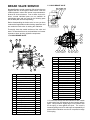
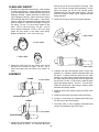
1
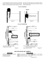
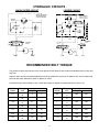
BRADEN
2ND GENERATION
“CH” SERIES
PLANETARY HOISTS
CH150A
CH175A
CH185A
CH230A
C2H150A
C2H175A
C2H185A
C2H230A
INSTALLATION, MAINTENANCE AND SERVICE MANUAL
PACR WINCH DIVISION
PB-154
8/99
Printed in U.S.A.
P.O. BOX 547 BROKEN ARROW, OK U.S.A. 74013
PHONE (918) 251-8511 FAX (918) 259-1575
www.paccarwinch.com
test
TABLE OF CONTENTS
FOREWORD . . . . . . . . . . . . . . . . . . . . . . . . . . . . . . . . . . . . . . . . . . . . . . .2
GENERAL SAFETY RECOMMENDATIONS . . . . . . . . . . . . . . . . . . . . . . . .3
BASIC OPERATION . . . . . . . . . . . . . . . . . . . . . . . . . . . . . . . . . . . . . . . . . .4
HOIST INSTALLATION . . . . . . . . . . . . . . . . . . . . . . . . . . . . . . . . . . . . . . . .6
WIRE ROPE INSTALLATION . . . . . . . . . . . . . . . . . . . . . . . . . . . . . . . . . . .6
WIRE ROPE WEDGES . . . . . . . . . . . . . . . . . . . . . . . . . . . . . . . . . . . . .7
HYDRAULIC CIRCUITS . . . . . . . . . . . . . . . . . . . . . . . . . . . . . . . . . . . . . . .8
RECOMMENDED BOLT TORQUES . . . . . . . . . . . . . . . . . . . . . . . . . . . . . .8
PREVENTIVE MAINTENANCE . . . . . . . . . . . . . . . . . . . . . . . . . . . . . . . . . .9
RECOMMENDED GEAR OIL . . . . . . . . . . . . . . . . . . . . . . . . . . . . . . . . . .10
TROUBLE SHOOTING . . . . . . . . . . . . . . . . . . . . . . . . . . . . . . . . . . . . . . .11
HOIST DISASSEMBLY . . . . . . . . . . . . . . . . . . . . . . . . . . . . . . . . . . . . . . .15
EXPLODED VIEW DRAWING AND PARTS KEY . . . . . . . . . . . . . . . . . . . .18
BRAKE CYLINDER SERVICE AND ASSEMBLY . . . . . . . . . . . . . . . . . . . .21
BRAKE CYLINDER TESTING . . . . . . . . . . . . . . . . . . . . . . . . . . . . . . .23
PLANET CARRIER SERVICE AND ASSEMBLY . . . . . . . . . . . . . . . . . . . .24
BRAKE CLUTCH SERVICE . . . . . . . . . . . . . . . . . . . . . . . . . . . . . . . . . . .27
HOIST ASSEMBLY . . . . . . . . . . . . . . . . . . . . . . . . . . . . . . . . . . . . . . . . . .29
REVERSING DIRECTION OF DRUM ROTATION . . . . . . . . . . . . . . . . . . .34
BRAKE VALVE SERVICE . . . . . . . . . . . . . . . . . . . . . . . . . . . . . . . . . . . . .36
METRIC CONVERSIONS . . . . . . . . . . . . . . . . . . . . . . . . . . . . . . . . . . . . .39
1
FOREWORD
Read this entire publication and retain it for future reference.
The following service instructions have been prepared to provide assembly, disassembly and maintenance information for
the BRADEN Model CH series winch. It is suggested that before doing any work on these units, all assembly and disassembly instructions should be read and understood.
Some pictures in this manual may show details or attachments that are different from your winch. Also, some components
have been removed for illustrative purposes.
Continuing product improvement may cause changes in your winch, which are not included in this manual. Whenever a
question arises regarding your BRADEN Winch or this manual, please contact BRADEN Service Department at 1-918-2518511, 08:00 - 16:30 hours, CST, Monday through Friday, for the latest available information.
MODEL NUMBER
AND
SERIAL NUMBER
MODEL NUMBER AND SERIAL NUMBER
When information on a hoist is needed, always refer
to the model number and serial number. Both are
located on the top of the motor side end plate as
indicated above.
EXPLANATION OF MODEL NUMBER
CH 150 A - 23 090 01 G - 1
CONSTRUCTION
HOIST
CH
150
A
23
090
01
G
1
MAX
RATING
DESIGN
MODEL
GEAR
RATIO
MOTOR
SIZE
DRUM
SIZE
DRUM
OPTION
OPTION
DESIGNATES CONSTRUCTION HOIST (C2H DESIGNATES TWO SPEED)
DESIGNATES 15,000 LB FIRST LAYER LINE PULL
DESIGNATES THE MODEL SERIES RELATING TO DESIGN CHANGES
DESIGNATES TOTAL GEAR REDUCTION
DESIGNATES HYDRAULIC MOTOR DISPLACEMENT IN CU IN/REV (DECIMAL POINT ELIMINATED
EXAMPLE 090 – 9.0 CU IN/REV)
DESIGNATES THE DRUM OPTION
DESIGNATES OTHER DRUM OPTIONS (G = GROOVED; M = MACHINED; P = RATCHET AND PAWL;
U = UNDERWOUND)
PERMITS TESTING AND INSPECTION PRE API2C FOR OFFSHORE CRANES
2
GENERAL SAFETY RECOMMENDATIONS
1.
Be certain equipment (boom, sheave blocks, pendants, etc.) is either lowered to the ground or blocked
securely before servicing, adjusting, or repairing
winch.
2.
Be sure personnel are clear of work area BEFORE
operating winch.
3.
Read all warning and caution tag information provided
for safe operation and service of winch.
4.
Inspect rigging and winch at the beginning of each
work shift. Defects should be corrected immediately.
5.
Keep equipment in good operating condition. Perform
scheduled servicing and adjustments listed in the
“Preventive Maintenance” section of this manual.
6.
An equipment warm-up procedure is recommended for
all start-ups and essential at ambient temperatures
below +40°F. Refer to “Warm-up Procedure” listed in
the “Preventive Maintenance” section of this manual.
7.
Do not exceed the maximum pressure (PSI) or flow
(GPM) stated in the winch specifications.
8.
Operate winch line speeds to match job conditions.
9.
Leather gloves should be used when handling wire
rope.
16. Use correct anchor for wire rope and pocket in drum.
17. Do not use knots to secure or attach wire rope.
18. The BRADEN designed wire rope anchors are capable
of supporting the rated load when installed properly.
For additional safety, ALWAYS maintain a minimum of
five (5) wraps of wire rope on the drum.
Safety and informational callouts used in this manual
include:
WARNING
CAUTION
!
!
WARNING – This emblem is used to warn
against hazards and unsafe practice which
COULD result in severe personal injury or death
if proper procedures are not followed.
10. Never attempt to handle wire rope when the hook end
is not free.
11. When winding wire rope on the winch drum, never
attempt to maintain tension by allowing wire rope to
slip through hands. Always use “Hand-Over-Hand”
technique.
!
CAUTION
CAUTION
!
CAUTION – This emblem is used to warn
against potential or unsafe practices which
COULD result in personal injury and product or
property damage if proper procedures are not
followed.
12. Never use wire rope with broken strands. Replace
wire rope.
13. Do not weld on any part of the winch.
14. Use recommended hydraulic oil and gear lubricant.
15. Keep hydraulic system clean and free from contamination at all times.
3
BASIC OPERATION
DESCRIPTION OF HOIST
The static brake system has three operating components:
The
1.
2.
3.
4.
5.
6.
7.
8.
9.
10.
1. Spring Applied, Multiple Friction Disc Static Brake
2. Brake Clutch Assembly
3. Hydraulic Piston and Cylinder
hoist is made up of the following sub-assemblies:
Hydraulic motor and brake valve
Drum, drum closure, ball bearings and oil seals
Support end plate and bearing support
Motor end plate and motor adapter
Tie plates
Brake clutch assembly
Brake cylinder assembly and multiple-disc brake parts
Primary planetary reducer
Secondary planetary reducer
Ring gear and adapter
Figure 2
Motor
Static
Brake
To
Tank
Brake
Valve
THEORY OF OPERATION
Pump
The primary sun gear, being coupled to the hydraulic motor
by the inner race of the brake clutch assembly, turns with
the motor. As the primary sun gear turns, the primary planet gears, which are meshed with the primary sun gear and
ring gear, walk around the stationary ring gear, causing the
primary carrier to turn in the same direction as the motor
shaft, but at a reduced speed. The primary carrier is
meshed with the output sun gear which, therefore, turns in
the same direction and at the same speed as the primary
carrier. The output sun gear causes the output planet gears
to walk around the ring gear, turning the output carrier and
drum in the same direction as the primary carrier, but at a
further reduced speed.
Control
Valve
Low Pressure Medium Pressure
High Pressure
Figure 3
Motor
Static
Brake
To
Tank
Brake
Valve
DUAL BRAKE SYSTEM – DESCRIPTION
Pump
The dual brake system consists of a dynamic brake system
and a static brake system.
Control
Valve
The dynamic brake system has two operating components:
Low Pressure Medium Pressure High Pressure
1. Brake valve assembly
2. Hydraulic motor
Figure 4
Motor
Static
Brake
The brake valve is basically a counterbalance valve. It contains a check valve to allow free flow of oil to the motor in
the hoisting direction and a pilot operated, spring-loaded
spool valve that blocks the flow of oil out of the motor when
the control valve is placed in neutral. When the control
valve is placed in the lowering position, the spool valve
remains closed until sufficient pilot pressure is applied to
the end of the spool to shift it against spring pressure and
open a passage. After the spool valve cracks open, the pilot
pressure becomes flow-dependent and modulates the
spool valve opening which controls the lowering speed.
See figures 2, 3 and 4
Brake
Valve
To
Tank
Pump
Control
Valve
Low Pressure Medium Pressure High Pressure
4
The static brake is released by the brake valve pilot pressure at a pressure lower than that required to open the pilot
operated spool valve. This sequence assures that dynamic braking takes place in the brake valve and that little, if
any, heat is absorbed by the friction brake.
When lowering a load very slowly for precise positioning, no
oil flow actually occurs through the winch motor. The pressure will build up to a point where the brake will release sufficiently to allow the load to rotate the motor through its own
internal leakage. This feature results in a very slow speed
and extremely accurate positioning.
The friction brake is a load holding brake only and has nothing to do with dynamic braking or rate of descent of a load.
The friction brake receives very little wear in the lowering
operation. All of the heat generated by the lowering and
stopping of a load is absorbed by the hydraulic oil where it
can be readily dissipated.
The brake clutch is splined to the primary sun gear shaft
between the motor and the primary sun gear. It will allow
this shaft to turn freely in the direction to raise a load and
lock up to force the brake discs to turn with the shaft in the
direction to lower a load. Figures 5 and 6.
Static Friction Brake Applied
Figure 5
The hydraulic cylinder, when pressurized, will release the
spring pressure on the brake discs, allowing the brake discs
to turn freely.
Sprag
Cams
DUAL BRAKE SYSTEM – OPERATION
When hoisting a load, the brake clutch which connects the
motor shaft to the primary sun gear, allows free rotation.
The sprag cams lay over and permit the inner race to turn
free of the outer race. Figure 5. The friction brake remains
fully engaged. The winch, in raising a load, is not affected
by any braking action. Figure 2.
Hoisting
When the lifting operation is stopped, the load attempts to
turn the primary sun gear in the opposite direction. This
reversed input causes the sprag cams to instantly roll
upward and firmly lock the shaft to the fully engaged friction
brake. Figure 6.
Permits free
shaft rotation
while hoisting
When the winch is powered in reverse, to lower the load,
the motor cannot rotate until sufficient pilot pressure is present to open the brake valve. Figures 3 & 4. The friction
brake within the winch will completely release at a pressure
lower than that required to open the brake valve. The extent
to which the brake valve opens will determine the amount of
oil that can flow through it and the speed at which the load
will be lowered. Increasing the flow of oil to the winch motor
will cause the pressure to rise and the opening in the brake
valve to enlarge, speeding up the descent of the load.
Decreasing this flow causes the pressure to lower and the
opening in the brake valve to decrease thus slowing the
descent of the load.
Figure 6
Static Friction Brake Applied
Sprag
Cams
Stopped,
Holding
Load
When the control valve is shifted to neutral, the pressure will
drop and the brake valve will close, stopping the load. The
friction brake will engage and hold the load after the brake
valve has closed.
Load attempts to rotate shaft in opposite direction.
Brake clutch locks sun gear shaft to friction brake.
5
INSTALLATION
GENERAL REQUIREMENTS
1. The hoist should be mounted with the centerline of the drum in
a horizontal position. The mounting plane can be rotated to any
position around this centerline.
6. The hoist directional control valve must be a three-position, fourway valve with a motor spool such that when the valve is in the
center position both work ports are opened directly to tank.
2. When mounting the hoist, use at least grade five bolts and nuts,
and use both mounting holes in each end gate.
7. The hydraulic oil filter should have a 10 micron nominal rating
and be a full-flow type.
3. It is important that the hoist be mounted on a surface that will not
flex when the hoist is in use, since this could bind the working
parts of the hoist. Also, be sure the hoist is mounted on a flat surface. If necessary, use shim stock to insure proper mounting.
The mounting surface should be flat within + or -.020 inches.
8. High quality hydraulic oil is essential for satisfactory performance
and long hydraulic system component life.
Oil having 150 to 330 SUS viscosity at 100°F (38°C) and viscosity index of 100 or greater will give good results under normal
temperature conditions. The use of an oil having a high viscosity index will minimize cold-start trouble and reduce the length of
warm-up periods. Ahigh viscosity index will minimize changes in
viscosity with corresponding changes in temperature.
4. Hydraulic lines and components that operate the hoist should be
of sufficient size to assure minimum back pressure at the hoist.
The motor manufacturer recommends that the back pressure
not exceed 100 psi for maximum motor seal life. 150 psi is the
maximum allowable back pressure. The standard CH150A,
CH175A, CH185A, CH230A, C2H150A, C2H175A, C2H185A
and C2H230A hoists are supplied with the motor internally
drained. If high back pressures are encountered, the motor can
be drained directly to tank to improve motor seal life. To insure
adequate static brake load holding ability, back pressure on the
hoist should not exceed 200 psi. For pressures exceeding 200
psi, consult Braden Engineering.
Maximum cold weather start-up viscosity should not exceed
5000 SUS with a pour point at least 20°F lower than the minimum temperature.
Under continuous operating conditions the temperature of the oil
at any point in the system must not exceed 180°. 120-140°F is
generally considered optimum.
In general terms; for continuous operation at ambient temperatures between 50 and 110°F, use SAE 20W; for continuous
operation between 10 and 90°F, use SAE 10W; for applications
colder than 10°F, contact the BRADEN Service Department.
The use of multi-viscosity oils is generally not recommended.
5. Make certain that the hoist drum is centered behind the first
sheave and the fleet angle does not exceed 1 ½ degrees. The
hoist should also be mounted perpendicular to an imaginary line
from the center of the drum to the first sheave to insure even
spooling.
WIRE ROPE INSTALLATION
!
WARNING
CAUTION
vent core slippage or loss of rope lay.
!
Take the free end of the wire rope and insert it through the
small opening on the cable drum. Loop the wire rope and
push the free end about 3/4 of the way back through the
pocket. Install the wedge as shown in figure 7, then pull the
slack out of the wire rope. The “dead” end of the rope
needs to extend slightly beyond the end of the wedge as
shown in figure 8.
THE CABLE ANCHORS ALONE ON HOISTS ARE NOT
DESIGNED TO HOLD RATED LOADS. Winch loads
applied directly to the wire rope anchor may cause the
wire rope to pull free and result in the sudden loss of load
control and cause property damage, personal injury or
death. A minimum of 3 wraps of wire rope must be left on
the drum barrel to achieve rated load.
Using a hammer and brass drift, drive the wedge as deep
into the pocket as possible to ensure it is fully seated and
no further movement is detected. Applying a load on the
wire rope will also help seat the wedge in the pocket.
The wedge and anchor pocket must be clean and dry. The
end of the wire rope being anchored to the drum must be
clean and dry and not frayed. Anything on the end of the
wire rope to keep it from fraying (i.e. tape or wire) must not
be in contact with the wedge when the installation is complete. Consult the wire rope manufacturer on the proper
treatment of the dead end of the wire rope. Some rope
manufacturers recommend when using rotation resistant
wire rope, that the rope end be seized, welded or brazed
before inserting the wire rope into the wedge socket to pre-
Check to ensure the wedge does not protrude from either
end of the pocket, causing it to interfere with proper spooling of wire rope onto the drum (see figures 9 & 10). If there
is interference or the wedge does not seat firmly, contact
the Braden Product Support Department at 918-251-8511
to determine the proper wedge size.
6
It is important that the wire rope have the proper tensioning
when it is installed on the drum. When the wire rope is first
installed, you should operate the hoist, with light to moder-
ate loads, with reeving that let’s you place these loads on
the block and the drum with all the rope off the drum except
for the last three wraps.
Correct Installation
Drive from
this side
Wedge and wire rope
fully seated in pocket
Figure 8
Figure 7
Incorrect Installations
Wedge pulled too far
through anchor pocket
Wedge not
fully seated
• Wire rope not tight against wedge
• Wedge may be too large
• “Dead” end of wire rope and/or wedge may
interfere with proper spooling
• Wedge may be too small
Figure 9
Figure 10
WIRE ROPE WEDGE PART NUMBERS
WINCH MODEL
WEDGE PART NO.
CH150A, C2H150A, CH185A, C2H185A . 24493* for 7/16 thru 5/8 in. (11 - 16 mm); 24494 3/4 thru 1 in. (19 - 25 mm)
CH230A and C2H230A . . . . . . . . . . . . . . 24493 for 7/16 thru 5/8 in. (11 - 16 mm); 24494* 3/4 thru 1 in. (19 - 25 mm)
CH175A and C2H175A . . . . . . . . . . . . . . 24492* for 7/16 in. thru 7/8 in. (11 - 22 mm)
* Standard Anchor
7
HYDRAULIC CIRCUITS
SINGLE SPEED CIRCUIT
2 SPEED CIRCUIT
WINCH ASSEMBLY
W/BRAKE VALVE
& STATIC BRAKE
WINCH ASSEMBLY
W/BRAKE VALVE
& STATIC BRAKE
BRAKE
VALVE
T
P
WINCH BRAKE
BRAKE
VALVE
BR
WINCH BRAKE
BR
A
DR
DR
CONTROL
VALVE
2-SPEED
SELECTOR
VALVE
CONTROL
VALVE
PUMP
PUMP
RECOMMENDED BOLT TORQUE
The general purpose torque shown in the chart applies to SAE Grade 5 bolts, studs and standard steel full, thick and
high nuts.
Higher or lower torques for special applications will be specified such as the use of spanner nuts, nuts on shaft ends,
jam nuts and where distortion of parts or gaskets is critical.
Lubricated torque values based on use of SAE 30wt engine oil applied to threads and face of bolt or nut.
Bolt Dia.
Inches
1/4
5/16
3/8
7/16
1/2
9/16
5/8
Thds per
Inch
20
28
18
24
16
24
14
20
13
20
12
18
11
18
Bolt Dia.
Inches
Torque LB-FT
Dry
Lubed
9
6
3/4
18
13
7/8
31
23
1
50
27
1 1/8
75
55
1 1/4
110
80
1 3/8
150
115
1 1/2
8
Thds per
Inch
10
16
9
14
8
14
7
12
7
12
6
12
6
12
Torque LB-FT
Dry
Lubed
265
200
420
325
640
485
790
590
110
835
1460
1095
1940
1455
PREVENTIVE MAINTENANCE
A regular program of preventive maintenance for your planetary winch is strongly recommended to minimize the need
for emergency servicing and promote safe, reliable winch operation.
Field experience, supported by engineering tests, indicate the three (3) service procedures listed below are the MOST
critical to safe, reliable winch operation and must be observed.
•
Regular Gear Oil Changes – every 1000 hours or six (6) months
•
Use of Proper Gear Oil – recommended type for prevailing ambient temperature
•
Annual Disassembly and Inspection of All Wear Items – in compliance with American National Standards Institute
(ANSI) specification B30.5c 1987 and American Petroleum Institute (API) recommended practice RP
2D section 3.
ating hours or six (6) months, whichever occurs first.
The gear oil must be changed to remove wear particles
that impede the reliable and safe operation of the
brake clutch and erode bearings, gears and seals.
Failure to change gear oil at these suggested minimum
intervals may contribute to intermittent brake slippage
which could result in property damage, severe personal injury or death.
The following minimum service intervals are specified
for operating hours of the prime mover.
Oil Level
Plug
The gear oil should also be changed whenever the ambient
temperature changes significantly and an oil from a different
temperature range would be more appropriate. Oil viscosity with regard to ambient temperature is critical to
reliable brake clutch operation. Our tests indicate that
excessively heavy or thick gear oil may contribute to intermittent brake clutch slippage. Make certain that the gear oil viscosity used in your winch is correct for your prevailing ambient
temperature. Failure to use the proper type and viscosity of
planetary gear oil may contribute to brake clutch slippage
which could result in property damage, severe personal injury or death. Refer to “Recommended Planetary Gear
Oil” for additional information.
1. Oil Level
The gear oil level should be checked every 500 operating hours or three (3) months, whichever occurs first.
To check the oil level, remove the plug located in the
drum support. The oil should be level with the bottom
of this opening. If additional oil in needed, refer to
“Recommended Planetary Gear Oil”.
3. Vent Plug
The vent plug is located in the drum support as shown.
It is very important to keep this vent clean and unobstructed. Whenever gear oil is changed, remove vent
plug, clean in solvent and reinstall.
Do not paint over the vent or replace with a solid plug.
4. Hydraulic System
The original filter element should be replaced after the
first fifty (50) hours of operation, then every 500 operating hours or three (3) months, or in accordance with
the equipment manufacturer’s recommendations.
2. Oil Change
5. Wire Rope
Inspect entire length of wire rope according to wire
rope manufacturers recommendations.
The gear oil should be changed after the first one hundred (100) hours of operation, then every 1,000 oper9
6. Mounting Bolts
clutch slippage and damage to brake friction discs or
seals. Oil viscosity with regard to ambient temperature
is also critical to reliable brake clutch operation. Our
tests indicate that excessively heavy or thick gear oil
may contribute to intermittent brake clutch slippage.
Make certain that the gear oil viscosity used in your
winch is correct for your prevailing ambient temperature.
Tighten all winch base mounting bolts to recommended torque
after the first one hundred (100) hours of operation, then every
1000 operating hours or six (6) months, whichever occurs first.
7. Warm-up Procedures
Awarm-up procedure is recommended at each start-up and is
essential at ambient temperatures below +40°F (4°C).
For simplicity, BRADEN has listed one (1) readily available product in each temperature range which has
been tested and found to meet our specifications. This
is not to say that other lubricant brands would not perform equally as well.
The prime mover should be run at its lowest recommended
RPM with the hydraulic winch control valve in neutral allowing
sufficient time to warm up the system. The winch should then
be operated at low speeds, forward and reverse, several times
to prime all lines with warm hydraulic oil, and to circulate gear
lubricant through the planetary gear sets.
WARNING
CAUTION
!
If the following lubricant brands are not available in
your area, make certain your lubricant vendor supplies
you with oil that is equivalent to those products listed
below.
!
Failure to properly warm up the winch, particularly
under low ambient temperature conditions, may result
in temporary brake slippage due to high back pressures attempting to release the brake, which could
result in property damage, severe personal injury or
death.
BRADEN planetary winches are factory filled with
Texaco Meropa 150 or equivalent API GL-2/3 gear oil.
9. Inspection
In compliance with ANSI specification number
B30.5c1987 and API Recommended Practice RP 2D
section 3, we recommend that the winch be disassembled for a thorough inspection of all wear items every
2,000 hours of operation or twelve (12) months,
whichever occurs first.
8. Recommended Planetary Gear Oil
Field experience, supported by extensive engineering
tests, indicates the use of the proper planetary gear oil
is essential to reliable and safe operation of the brake
clutch and obtaining long gear train life.
!
WARNING
CAUTION
A. Bearings and Gears – Refer to DISASSEMBLY
OF WINCH, item17 on page 19; and PLANET
CARRIER SERVICE, item 3 on page 20.
!
B. Brake Cylinder – Refer to MOTOR SUPPORT –
BRAKE CYLINDER SERVICE, Clean and Inspect,
pages 22 and 23.
Failure to use the proper type and viscosity of planetary gear oil may contribute to intermittent brake clutch
slippage which could result in property damage,
severe personal injury or death. Some gear lubricants
contain large amounts of EP (extreme pressure) and
anti-friction additives which may contribute to brake
C. Brake Clutch – Refer to BRAKE CLUTCH SERVICE,
item 4 on page 26.
RECOMMENDED GEAR OIL
PREVAILING AMBIENT TEMPERATURE
oF
-40
-30
-20
-10
0
10
20
30
40
50
60
70
80
90
100
110
120
130 oF
TEXACO MEROPA 220 OR EQUIVALENT
API GL-2/3
TEXACO MEROPA 150 OR EQUIVALENT
API GL-2/3
MOBIL SHC 630
SYNTHETIC
oC
-40
-30
NOT RECOMMENDED FOR SEVERE APPLICATIONS SUCH AS: OFFSHORE CRANES,
SUSTAINED FAST DUTY CYCLES OR FREQUENT LIFTING.
-20
-10
0
10
10
20
30
40
50 oC
TROUBLE SHOOTING
!
WARNING
CAUTION
!
If a winch ever exhibits any sign of erratic operation, or load control difficulties (i.e. load creeping or chattering) appropriate troubleshooting tests and repairs should be performed immediately. Continued operation in this manner may
result in property damage, serious personal injury or death.
TROUBLE
PROBABLE CAUSE
REMEDY
A
The winch will not lower the load
or not lower the load smoothly.
1.
The problem could be a plugged
or loose pilot orifice. The pilot orifice is a small pipe plug with a
hole drilled through it, located
behind the pilot port fitting on the
brake valve. If it becomes
plugged, it will prevent the pilot
pressure, from the manifold, from
opening the brake valve. If it
becomes loose, it will allow an
unregulated amount of oil in to
operate the brake valve which
cause erratic brake valve operation.
Remove the pilot hose and fitting
from the brake valve, then use a
5/32 inch Allen wrench to remove
the pilot orifice. The diameter of
the orifice is approximately .020
inches. Clean and install the pilot
orifice tightly in the brake valve.
2.
The friction brake may not be
releasing as a result of a defective brake cylinder seal.
Check brake cylinder seal as follows:
A.
Disconnect the swivel tee from
the brake release port. Connect a
hand pump with accurate 0-2000
psi gauge and shut-off valve to
the –4 J.I.C. fitting in the brake
release port.
B.
Apply 1000 psi to the brake.
Close shut-off valve and let stand
for five (5) minutes.
C.
If there is any loss of pressure in
five (5) minutes, the brake cylinder should be disassembled for
inspection of the sealing surfaces
and replacement of the seals.
Refer to “Motor Support-Brake
Cylinder Service”.
NOTE: If the brake cylinder seal
is defective you will usually find
oil leaking from the winch vent
plug.
3.
Friction brake will not release as
a result of damaged brake discs.
11
Disassemble brake to inspect
brake discs. Check stack-up
height as described in “Motor
Support-Brake Cylinder Service”.
TROUBLE
PROBABLE CAUSE
REMEDY
B
Oil leaks from vent plug.
1. Same as A2.
Same as A2.
2. Motor seal may be defective as a
result of high system back pressure or contaminated oil.
System back pressure must not
exceed 150 psi.
Inspect
hydraulic system for a restriction
in the return line from the control
valve to the reservoir. Be sure
control valve and plumbing is
properly sized to winch motor.
Oil analysis may indicate contamination has worn motor shaft and
seal. Thoroughly flush entire
hydraulic system and install new
filters and oil. Install new motor
seal.
C
The brake will not hold a load with the
control lever in neutral.
1.
Excessive system back pressure
acting on the brake release port.
The same as Remedy 2 of
Trouble B2.
2.
Friction brake will not hold due to
worn or damaged brake discs.
Same as Remedy 3 of Trouble
A3.
3.
Brake clutch is slipping.
Improper planetary gear oil may
cause the brake clutch to slip.
Drain old gear oil and flush winch
with solvent. Thoroughly drain
solvent and refill winch with recommended planetary gear oil listed in “Preventive Maintenance”.
Brake clutch may be damaged or
worn. Disassemble and inspect
brake clutch as described in
“Brake Clutch Service”.
D
The winch will not hoist the rated load
1.
2.
The winch may be mounted on an
uneven or flexible surface which
causes distortion of the winch
base and binding of the gear
train. Binding in the gear train will
absorb horsepower needed to
hoist the rated load and cause
heat.
System relief valve may be set
too low. Relief valve needs
adjustment or repair.
12
Reinforce mounting surface.
If necessary, use shim stock to
level winch. Refer to “Winch
Installation”.
First loosen, then evenly retighten all winch mounting bolts to
recommended torque.
Check relief pressure as follows:
A.
Install an accurate 0-4000 psi
gauge into the inlet port of the
brake valve.
TROUBLE
PROBABLE CAUSE
TROUBLE “D” CONTINUED FROM
PREVIOUS PAGE
REMEDY
B.
Apply a stall pull load on the
winch while monitoring pressure.
C.
Compare gauge reading to winch
specifications. Adjust relief valve
as required.
NOTE: If pressure does not increase
in proportion to adjustment, relief
valve may be contaminated or
worn out. In either case, the relief
valve may require disassembly or
replacement.
3.
Be certain hydraulic system temperature is not more than 180
degrees F. Excessive hydraulic
oil temperatures increase motor
internal leakage and reduce
motor performance.
Same as remedies for Trouble D1
& D2.
Winch line pull rating is based on
1st layer of wire rope.
Refer to winch performance
charts for additional information.
5.
Rigging and sheaves not operating efficiently.
Perform rigging service as recommended by crane manufacturer.
1.
Same as D1.
Same as remedies for Trouble
D1.
2.
Be certain that the hydraulic system temperature is not more than
180 degrees F. Excessive
hydraulic oil temperatures may
be caused by:
A.
Plugged heat exchanger.
Thoroughly clean exterior and
flush interior.
B.
Too low or too high oil level in
hydraulic reservoir.
Fill/drain to proper level.
C.
Same as D2.
Same as remedies for Trouble
D2.
D.
Hydraulic pump not operating efficiently.
Prime mover low on horsepower
or R.P.M. Tune/adjust prime
mover.
4.
E
The winch runs hot.
Same as remedies for Trouble
E2.
Check suction line for damage.
If pump is belt driven, belts are
slipping. Replace/tighten belts.
Pump worn. Replace pump.
3.
Excessively worn or damaged
internal winch parts.
13
Disassemble winch to inspect/replace
worn parts.
TROUBLE
PROBABLE CAUSE
REMEDY
F
Winch “chatters” while raising rated
load.
1.
Same as D2.
Same as remedies for Trouble D2.
2.
Hydraulic oil flow to motor may be
too low.
Same as remedies for Trouble E2.
3.
Controls being operated too
quickly.
Conduct operator training as required.
1.
The winch may be mounted too
close to the main sheave, causing the fleet angle to be more
than 1½ degrees.
Check mounting distance and
fleet angle. Reposition winch as
required.
2.
The winch may not be mounted
perpendicular to an imaginary
line between the center of the
cable drum and the first sheave.
Refer to “Winch Installation”.
3.
Could possibly be using the
wrong lay rope. There is a distinct
advantage in applying rope of the
proper direction of lay. When the
load is slacked off, the several
coils on the drum will stay closer
together and maintain an even
layer. If rope of improper lay is
used, the coils will spread apart
each time the load is removed.
Then, when winding is resumed,
the rope has a tendency to crisscross and overlap on the drum.
The result is apt to be a flattened
and crushed rope.
Consult wire rope manufacturer
for recommendation of wire rope
that best suits your application.
4.
The winch may have been overloaded, causing permanent set in
the wire rope.
Replace wire rope and conduct
operator/rigger
training
as
required.
G
The wire rope does not spool smoothly on the drum.
14
DISASSEMBLY PROCEDURE FOR HOIST
1. Remove the wire rope from the hoist drum and align
the drain plug in the drum with the hole in the support
end plate before removing the hoses and mounting
bolts. After the hoist is removed from its mounting,
clean the outside surfaces.
4. Begin the disassembly by standing the hoist on the
end opposite the motor. Tag and remove the hydraulic
hoses that connect the brake valve and the motor
(manifold in the case of a two-speed motor) to the
brake release port.
2. To drain the oil, screw a short piece of 1” pipe into the
larger threads of the drain hole.
5. Remove the four (4) capscrews and lockwashers
securing the motor and lift the motor off the hoist.
Remove and discard the O-ring installed on the outside of the motor pilot.
3. Use a 3/8” drive extension to remove the drain plug
through the pipe. If the drain holes were not aligned
before the hoist was removed from its mounting, the oil
can be drained through the fill/vent plug in the bearing
support by turning the hoist up on the bearing support
end.
6. Remove the sixteen (16) capscrews and lockwashers
(20 in the CH185A and C2H185A models) from the two
(2) tie plates, and remove the plates.
15
7. Remove the tee fitting from the brake cylinder nipple.
11. Remove the brake plate spacer and brake and friction
discs.
8. Remove the eight (8) capscrews and lockwashers from
the motor adapter, and remove the motor adapter.
Remove and discard the O-ring that was under the
motor adapter.
12. Remove the brake cylinder assembly, and place it on a
clean, dry surface so as not to damage the splines.
Refer to the section on disassembly of the brake cylinder assembly.
9. Remove the brake cylinder nipple, then remove the
motor end plate.
10. Remove the brake clutch assembly from the brake
cylinder. Refer to the section on disassembly of
the brake clutch assembly.
13. Next, remove the primary sun gear.
16
14. Remove the cable drum closure by using two (2) capscrews from the motor adapter and a short piece of
chain. Lift the closure out of the drum. Remove and
discard the O-ring and the seal. Inspect the bearing
for wear. If replacement is necessary, use a bearing
driver to remove the bearing.
17. Remove the primary planet carrier assembly. Refer to
the section on disassembly of the primary planet carrier assembly.
18. Remove the thrust bearing that was under the primary
planet carrier assembly, then remove the output sun
gear.
15. Lift out the ring gear adapter.
19. Lift out the ring gear. Inspect the gear for abnormal
wear or pitting.
16. Remove thrust bearing and two races.
17
20. Remove the output planet carrier assembly. You can
make hooks like the ones shown to make removal
easier. Refer to the section on disassembly of the output planet carrier assembly.
22. Turn the drum over and remove and discard the seal.
Inspect the bearing in the end of drum. If replacement
is necessary, use a bearing driver to remove the bearing.
21. Lift the drum off the support end plate.
23. Check the bearing support sealing surface for nicks
and burrs. It is not necessary to remove the bearing
support from the support end plate unless it has been
damaged.
18
BRAKE CYLINDER SERVICE
3. Turn the brake cylinder on end with the large end up.
Remove the spiral retaining ring and lift out the brake
piston plate.
1. Turn the brake cylinder on end with the large end
down. Use the special compression tool or a shop
press to compress the backup plate in order to remove
the retaining ring.
!
CAUTION
CAUTION
!
CAUTION: Make certain that the threaded rod of the
compression tool fully engages the lower plate. If a
press is used, be careful not to damage any parts by
applying too much pressure.
Remove the retaining ring with snap ring pliers. Be
careful to not let the pliers slip out of the retaining ring.
Release the compression tool by holding the threaded
rod stationary while backing off the nut.
4. Turn the brake cylinder over and pull the piston out.
Remove and discard the O-rings. Inspect the backup
rings for nicks or cuts, and replace if necessary. Be
careful not to damage the O-ring groove surfaces.
2. Remove the spring guide. The backup plate, belleville
springs and spring guide will come out together.
Closely inspect the spring guide for damage that might
prevent the springs from moving freely in an axial
direction. Also inspect the springs for cracks and
material displacement. Replace any defective parts.
5. Inspect the brake cylinder for nicks and scratches on
the O-ring sealing area. Check the internal splines for
notches that might prevent the brake discs from sliding
freely. Be careful not to damage the O-ring sealing
surfaces.
19
SECOND GENERATION CH SERIES EXPLODED VIEW AND PARTS KEY
45
46
46
42
69
43
71
41
64
72
59
29
40
27
28
30
29
38
31
36
37
101
62
38
35
32
55
37
26
102
100
34
65
39
58
70
4
53
57
8
54
5
74
6
56
7
24
10
68
13
9
11
18
12
17
15
21
76
20
19
67
3
66
14
73
2
61
50
43
137
60
136
49
48
43
51
129
135
140
1 3 3A
141
122
130
133
* These items NOT SERVICED SEPARATELY.
Entire brake clutch assembly must be
replaced.
134
131
143
142
128
127
132
125
123
126
Two Speed Motor
(-1 option)
124
20
Refer to BRADEN Second Generation CH
Series Material List (Publication 11-18) for part
numbers.
ITEM
2
3
4
5
6
7
8
9
10
11
12
13
14
15
17
18
19
20
21
24
26
27
28
29
29
30
31
32
34
35
36
37
38
39
40
41
42
DESCRIPTION
Brake Cylinder
Brake Piston
Brake Piston Plate
Backup Plate
Belleville Spring
Spring Guide
Retaining Ring
Snap Ring
Snap Ring
O-Ring
O-Ring
Backup Ring
Backup Ring
Street Elbow - 45o
Outer Brake Race*
Inner Brake Race*
Snap Ring
Sprag Bearing Retainer
Sprag Clutch*
Sprag Bearing
Primary Planet Carrier
Primary Planet Gear
Primary Planet Gear Shaft
Thrust Washer
Thrust Washer
Roller Bearing
Spirol Pin
Thrust Washer
Output Planet Carrier
Output Planet Gear
Output Planet Gear Shaft
Thrust Washer
Roller Bearing
Spirol Pin
Support End Plate
Bearing Support
Capscrew
QTY.
1
1
1
1
8
1
1
1
1
1
1
1
1
1
1
1
2
2
1
1
1
3
3
6
6
3
3
1
1
3
3
6
6
3
1
1
8
140
143
127
142
128
139
131
133
130
135
122
132
134
124
129
125
136
126
137
123
Single Speed Motor
(-1 option)
21
ITEM
43
44
45
46
46
48
49
50
51
53
54
55
56
57
58
59
60
61
62
64
65
66
67
68
69
70
71
72
73
74
76
100
101
102
122
123
124
125
126
127
128
129
130
131
132
133
133a
134
135
135
136
137
139
140
142
143
DESCRIPTION
Lockwasher
Reducer Bushing
Relief Valve
Sight Glass
Pipe Plug
Motor End Plate
Motor Adapter
O-Ring
Capscrew
Ring Gear
Ring Gear Adapter
Primary Sun Gear
Cable Drum Closure
Output Sun Gear
Thrust Washer
Cable Drum
Capscrew
Tie Plate
Bearing Spacer
Ball Bearing
Ball Bearing
Brake Disc
Friction Disc
O-Ring
Oil Seal
Oil Seal
Cable Anchor Wedge
Plug
Brake Plate Spacer
Retaining Ring
Pipe Nipple
Bearing Race (.092" thick)
Thrust Bearing
Bearing Race (.063" thick)
Hydraulic Motor
Brake Valve
O-Ring
O-Ring
Capscrew
o
Elbow Fitting (90 )
Hose Assembly
Fitting
o
Elbow Fitting (90 )
Hose Assembly
Tee Fitting
Needle Valve
Elbow Fitting (90o)
Fitting
Hose Assembly
Tee Fitting
Tee Fitting
Plug
Elbow Fitting (90o)
Warning Tag
Lockwasher
Capscrew
QTY.
36
1
1
1
1
1
1
1
8
1
1
1
1
1
1
1
16
2
3
1
1
10
9
1
1
1
1
1
1
1
1
1
1
1
1
1
1
1
4
1
1
1
1
1
1
1
1
1
1
1
1
1
1
1
4
4
BRAKE CYLINDER ASSEMBLY
5. Install the eight (8) belleville springs over the spring
guide. The first one should rest against the snap ring
on the spring guide, with the concave side facing the
snap ring. The second spring should be installed with
its convex side facing the snap ring. Alternate the
remaining six (6) springs until all eight (8) are in place.
1. Lubricate O-rings and backup rings with oil and install
them on the brake piston. The concave surface of the
backdrop ring must be next to the O-ring. Let the
assembly set for 10 minutes in order for the O-rings
and backup rings to return to their original shape.
2. Here are the backup rings and O-rings installed correctly. The backup rings must be to the outside of the
O-rings.
6. Next, place the backup plate over the spring guide so
that it rests on the top spring. Then, insert the spring
guide, springs and backup plate into the brake cylinder.
3. Lubricate the outside of the piston with oil or grease.
4. With the brake cylinder resting on its large end, insert
the piston into the brake cylinder. Be careful not to cut
the O-rings or backup rings.
22
7. Use a press or the special compression tool to compress the springs. Make certain the threaded portion
of the compression tool fully engages the lower plate.
Install the retaining ring using snap ring pliers. Be
careful to not let the pliers slip out of the retaining ring.
9. Now pressure check the brake cylinder assembly with
the hand pump connected to the 1/8” NPTF elbow in
the top of the assembly.
Apply 1000 psi and let the unit set for 5 minutes. If the
gauge does not register a pressure drop, it means you
have installed the O-rings and backup rings correctly.
After making certain the retaining ring is in place,
release the compression tool slowly, holding the
threaded portion of the tool stationary, while backing
off the nut.
8. Turn the assembly over and place the brake piston
plate over the brake piston. Install the spiral retaining
ring in the groove in the brake piston.
23
OUTPUT PLANET CARRIER SERVICE
3. To disassemble the primary planet carrier assembly,
the steps are the same as for the output planet carrier
assembly, except there is only one bearing for each
gear. Also, the primary carrier has a thrust washer
inside that can be removed after the planet gears are
removed.
4. If the rollers show any sign of spalling, corrosion, discoloration, material displacement or abnormal wear,
the bearing should be replaced. Likewise, the cage
should be inspected for unusual wear or deformation,
particularly the cage bars. If there is any damage that
will impair the cage’s ability to separate, retain and
guide the rollers properly, the bearing should be
replaced. The thrust washer contact areas should be
free from any surface irregularities that cause excessive abrasion or friction. The gears should be inspected for abnormal wear or pitting. Replace if necessary.
1. Drive the three (3) spiral pins into the center of the
planet gear shafts.
2. Remove one (1) planet gear shaft, two (2) thrust washers, two (2) roller bearings and one (1) planet gear
from each of three (3) locations in the carrier. The
CH150A, C2H150A, CH175A and C2H175A also have
a bearing spacer between each pair of bearings that
has to be removed.
5. Use a punch to drive the spiral pins out of the planet
gear shafts. The same surface and material conditions
that are detrimental to the life of the bearings and
thrust washers also apply to the contact areas on the
shafts and carrier.
24
OUTPUT PLANET CARRIER ASSEMBLY
1. Insert two bearings into a gear (when assembling the
output planet carrier assembly for a CH150A,
C2H150A, CH175A or C2H175A, install a bearing
spacer between the two bearings). Place a thrust
washer on each side of the gear and install it in a carrier opening. Slide a shaft through the carrier, thrust
washers, bearings and gear.
3. Drive a spiral pin into place. Note that it is slightly
recessed in the carrier when it is in the proper position.
Use a center punch to dent the carrier next to the hole
as shown. This will distort the hole so the pin will not
work itself out. Repeat these steps for each of the
three planet gears.
2. Align the hole in the carrier and shaft so a spiral pin
can be installed. Always use a new 3/16” x ¾” spiral
pins when assembling these carriers. Use spiral pins,
because they are much stronger than roll pins.
4. This is how the output planet carrier should look after
you assemble it.
To assemble the primary planet carrier assembly, the
steps are the same as for the output planet carrier
assembly, except there is only one bearing for each
gear. Also, the thrust washer must be installed inside
the carrier on the hub end before the planet gears are
installed.
25
CLEAN AND INSPECT
The thrust washer contact areas should be free from
any surface irregularity that causes excessive abrasion
or friction.
Thoroughly clean all of the parts in a good grade of
cleaning solvent; one that is not flammable, not toxic
and will not cause skin rashes. If necessary, use rubber gloves.
Finally, the shafts and carrier should be checked
where there is roller or thrust washer contact. The
same surface and material conditions that are detrimental to the life of the bearing and thrust washer also
apply to the contact areas on the shaft and carrier.
Inspect all parts for wear, nicks, scratches and damage
that would render them unusable. If a part is questionable, it is better to replace it rather than take a chance
on premature failure when the hoist is placed back in
service.
If the hoist was disassembled only to replace damaged
seals after a short period of service, it is not necessary
to replace the bearings. Experience and common
sense, along with a good inspection, will determine if
they can be used again.
Always replace O-rings, seals and spiral pins.
Sometimes it is permissible to reuse bearings and
bushings . . . it depends on how much use they have
had.
Always coat O-rings, bearings, bushings and the rubber parts of seals with oil or grease during assembly.
Use a sealing compound on the outside diameter of
seals and a light coat of thread sealing compound or
sealing tape on pipe fittings and plugs. Be careful not
to get this compound or tape inside parts and passages which conduct oil.
At regular service intervals, the cage and roller bearing
assemblies and thrust washers in the planet carrier
assemblies should be inspected to insure beyond any
doubt that they will function properly when re-installed.
The rollers should not exhibit any surface irregularities.
If the rollers show any sign of spalling, corrosion, discoloration, material displacement or abnormal wear,
the bearings should be replaced. Likewise, the cage
should be inspected for unusual wear or deformation,
particularly the cage bars. If there is any damage that
will impair the cage’s ability to separate, retain and
guide the rollers properly, the bearing should be
replaced.
26
BRAKE CLUTCH SERVICE
DISASSEMBLY
4. Next, slide the sprag clutch out, inspect the sprag
clutch closely for abnormal wear, cracks, pitting or corrosion. Check small clips for breakage or bright spots;
the signs of excessive wear. Unless the outer race or
remaining sprag bushing is damaged or shows excessive wear, there is no need for further disassembly. If
disassembly is necessary, remove the bushing according to the procedure covered in Step No. three (3). All
brake clutch assembly parts should be thoroughly
cleaned and inspected before assembly.
1. Remove the snap ring and sprag bushing retainer from
one end only.
!
WARNING
CAUTION
!
The polished surfaces of the races and sprag cams
must be perfectly smooth to insure positive engagement of the clutch. The slightest defect may reduce
brake clutch effectiveness, which could result in property damage, severe personal injury or death. It is
generally recommended to replace the entire brake
clutch assembly if any component is defective.
2. Pull the inner race out. Examine the race for scoring,
wear or indentations caused by the sprag cams. If the
inner race is not completely smooth, the entire brake
clutch assembly must be replaced.
ASSEMBLY
1. Press a sprag bushing into the outer race, using a
mechanical or hydraulic press. A flat plate of approximately the same diameter as the bushing flange outside diameter should be placed between the press and
bushing during assembly to protect the bushing. Be
certain the bushing flange is against the shoulder in
the outer race.
3. Use a screwdriver and mallet to remove the sprag
bushing from one end of the outer race. There are four
special cut-outs in the bushing for this purpose. Be
careful not to damage the bushing inside surface. If a
bushing’s inside surface is damaged or shows wear,
replace it.
27
6. Turn the assembly over with the snap ring down.
Install the second retainer and snap ring. Make certain the snap ring is seated in the groove properly.
2. Turn the assembly over and install the sprag clutch in
the bore of the outer race.
3. Press the remaining bushing into the race. Again,
make sure the bushing is against the shoulder.
4. Next, install a sprag bushing retainer, then a snap ring
on the inner race. Be sure the snap ring is seated in
the snap ring groove.
7. This is a completed brake clutch assembly.
!
WARNING
CAUTION
!
Be certain the snap ring is seated in the groove in the
splined bore of the inner race. This snap ring will
keep the brake clutch assembly correctly positioned in
the center of the friction brake pack. Binding of the
brake or brake failure may occur if this snap ring is
omitted.
5. Slide the inner race through the bushings and sprag
clutch (the race will have to be rotated in the freewheeling direction to start it through the sprag clutch).
If the inner race will not go through the bushings, the
bushings have probably been damaged and should be
replaced.
28
HOIST ASSEMBLY
3. Turn the drum over, and set it down on the bearing
support. Be careful not to damage the seal when lowering the drum onto the bearing support.
1. Clean all parts before reassembling. The first step is
to lay the support end plate down with the bearing
support up. Lubricate the sealing and bearing lands
on the bearing support.
NOTE: If the bearing support was removed from the
end plate, reinstall it with eight (8) capscrews and lockwashers, making certain two (2) large holes in the end
plate line up with the cutouts in the bearing support.
4. Lower the output planet carrier assembly into the
drum, making certain that the teeth on the carrier
mesh with the teeth in the drum.
2. Install a new bearing in the drum if replacement is necessary, making certain to press it against the shoulder
in the bottom of the bearing bore. Coat the outside
diameter of the new seal with a good grade of sealant.
Turn the spring side of the seal next to the bearing,
and press the seal into the seal bore, leaving it flush
with the surface shown.
5. Install the ring gear. The ring gear teeth must mesh
with the output planet gears.
29
9. Install the ring gear adapter, hub end up, meshing the
adapter with the ring gear.
6. Install the output sun gear and the thrust washer.
Center the thrust washer on the output carrier so the
primary carrier pilot can be installed in it.
10. Install a new bearing in the drum closure if replacement is necessary, making certain to press it against
the shoulder in the bottom of the bearing bore. Coat
the outside diameter of the new seal with a good
grade of sealant. Turn the spring side of the seal
toward the bearing, and press the seal into the seal
bore, leaving it flush with the surface shown. Lubricate
the new O-ring and install it on the drum closure.
Lubricate the large diameter on the closure and install
the closure in the drum.
7. Install the primary planet carrier assembly in the ring
gear, meshing the planet gears with the ring gear. The
hub goes down, engaging the output sun gear. Be
sure the pilot enters the thrust washer.
8. Install thrust bearing and two race as shown. The thinner thrust race (.063 thick) goes next to the planet carrier and the thicker thrust race (.092 thick) goes next to
the ring gear adapter. The needle thrust bearing of
course goes between the two races. Not all units have
this design revision using the thrust washer (see Parts
Breakdown for details).
11. Install the primary sun gear, meshing its teeth with the
primary planet gears.
30
15. Install the brake discs. Start with a brake disc and end
with a brake disc. Alternate brake and friction discs
until there are nine (9) of the friction discs and ten (10)
of the brake discs.
12. Install the brake cylinder assembly over the primary
sun gear, making certain the brake cylinder engages
the ring gear adapter teeth.
16. Install the brake plate spacer on top of the brake discs.
13. Install the brake clutch assembly over the primary sun
gear. When installed correctly, the outer race should
turn freely in the same direction as the drum turns to
spool wire rope out. For most Braden assemblies, this
will be clockwise as viewed from the motor end.
17. Measure the brake stack-up as shown. The measurement should be a minimum of 3/16” from the top of the
brake plate spacer to the top of the brake cylinder. If
the measurement is less than 3/16”, remove the brake
plate spacer and add a brake disc to the top of the
brake package. Replace the brake plate spacer and
repeat procedure. Do not exceed an overall height of
¼”.
14. Before installing the brake discs and friction discs,
check their condition. Both kinds of discs should be
flat and their teeth should not be pointed. The friction
discs should have groove in the friction material.
Replace discs, if necessary.
31
21. Install the tie plates next. Position the plates so that
the curved part is toward the top of the hoist and curving away from the drum. Install the sixteen (16) capscrews and lockwashers (twenty for CH185A and
C2H185A).
18. Install the motor end plate and then the brake cylinder
nipple, using a good grade of thread sealant.
19. Lubricate the o-ring and install it on the outside of the
brake cylinder. Push it down until it’s resting against
the motor end plate.
22. Install the tee and hydraulic hoses at this time. Use a
good grade of thread sealant, being careful not to get
it in the hydraulic lines, as it could block an orifice in
the brake valve. The long hose should point to the
right as viewed from the motor end.
20. Install the motor adapter with eight (8) special
BRADEN capscrews and lockwashers.
23. Lubricate and install a new O-ring around the pilot on
the motor.
32
24. Engage the motor shaft in the brake clutch assembly
inner race, and lower the motor into place. Install four
(4) capscrews and lockwashers
26. After the hoist assembly is complete, check all capscrews and fittings to make certain they have been
tightened correctly. Refill the hoist with the recommended oil listed under maintenance suggestions.
25. Install the hydraulic hoses as shown, then tighten.
Continued on illustration no.26.
33
REVERSING DIRECTION OF DRUM ROTATION
This procedure applies in general terms to standard hoists with Commercial Intertech gear
motors. For information concerning hoists with other types of motors, consult the BRADEN
Service Department at the phone number listed in the FOREWORD section of this manual.
Motor Case Drain
Lowering
Port
Drn
“A”
Motor Case Drain
Brake
Valve
Hydraulic
Motor
Br
Lowering
Port
Drn
“B”
M
M = Manifold Block
Brake
Valve
Hydraulic
Motor
M
Br
Hoisting
Port
Hoisting
Port
Brake Release Circuit
Brake Release Circuit
In order to change the direction of drum rotation, 2 things must be changed on the hoist. First, the motor must be made
to rotate in the opposite direction. This is done by exchanging positions of the brake valve and manifold block on the
motor. Secondly, the brake clutch assembly must be made effective for the opposite driection of rotation. This is done
by reversing the brake clutch.
Figures “A” and “B” above show typical motor installations. Note that the only difference between the two drawings is
the motor is rotated 180o (the “belly” of the motor moves to the opposite side). If the motor shaft in figure “A” rotates
clockwise when the hoisting port is pressurized, the motor shaft in figure “B” will rotate counterclockwise.
1. Stand the hoist up on the motor support with the motor
up and secure in this position. Remove the four capscrews securing the brake valve to the motor.
Remove the four capscrews securing the manifold
block to the motor. Disconnect the motor case drain
hose at the motor. NOTE: Some installations have the
brake release hose connected directly to the motor,
instead of to the manifold block as shown above. In
these cases, disconnect the brake release hose from
the motor.
2. Before removing the motor, it is a good idea to mark
the position of the motor in relation to the hoist, since
it will be rotatled 180o when re-installed. Remove the
capscrews securing the motor to the hoist and carefully remove the motor.
4. Remove the snap ring and sprag bushing retainer from
one end only of the brake clutch assembly.
3. Remove the brake clutch assembly from the hoist.
Carefully inspect the splines on both ends of the inner
race.
a. If they are the same, the entire brake clutch
assembly can be turned over and re-installed in the
hoist. Before installing the brake clutch, be sure
the inner race turns free in the same direction the
drum will turn to haul-in wire rope. An easy way to
check the rotation is to hold the outer race in one hand
and rotate the inner race. Proceed to step 8.
b. If the splines in each end of the inner race are not
the same, proceed to step 4.
5. Pull the inner race out. Examine the race for scoring,
wear or indentations caused by the sprag cams. If the
inner race is not completely smooth, the entire brake
clutch assembly must be replaced.
34
6. Turn the sprag assembly around and slide the inner
race (with 1 snap ring and bushing retainer) through
the bushing and sprag clutch (the race will have to be
ratated in the free-wheeling direction to start it through
the sprag clutch). Install the remaining bushing retainer and snap ring. Make sure the snap ring is properly
seated in the groove.
7. Install the brake clutch assembly into the hoist.
Before installing the brake clutch, be sure the
inner race turns free in the same direction the
drum will turn to haul-in wire rope. An easy way to
check the rotation is to hold the outer race in one hand
and rotate the inner race.
8. Install a new O-ring on the motor pilot. Rotate the
motor 180o from its original position and install it onto
the hoist. Install and tighten motor capscrews to recommended torque.
9. Install new O-rings in the brake valve and manifold
block. Attach the brake valve and manifold block to
the motor using the original capscrews and tighten to
recommended torque.
10.Connect the motor case drain hose to the motor case
drain port. NOTE: On two speed motors, the case
drain and shift drain ports should be connnected
directly to tank. DO NOT use the drain connection on
the brake valve. Se “TWO SPEED MOTOR CASE
DRAIN PLUMBING” for additional information.
11. If your hoist had the brake release hose connected
directly to the motor, the original motor port must be
plugged and the hose connected to the motor pressure port near the manifold block (lowering port).
12.Operate the winch slowly in both directions and check
for oil leaks and/or unusual sounds. The hoist should
operate smoothly in both directions. Refer to “WIRE
ROPE INSTALLATION” and properly install wire rope
onto the winch drum.
13.Before returning the hoist to full service, a light load
should be lifted and held a few feet off the ground to
be sure the static brake is functioning properly. The
winch should also be able to slowly lower the load in a
controlled manner. If the winch does not perform
either of these functions, refer to “TROUBLE SHOOTING” FOR ADDITIONAL INFORMATION.
35
BRAKE VALVE SERVICE
1 1/2 INCH BRAKE VALVE
20
Standard Braden second generation CH series hoists are
supplied with one of two types of brake valves. Both are
reliable hydraulic valves with internal componentsmanufactured to close tolerances. Due to these close tolerances, several individual parts are not available as
replacement parts and are noted in the following parts
lists as NSS (Not Serviced Separately).
Before disassembling the brake valve, be sure you have
conducted all applicable trouble shooting operations and
are certain the brake valve is causing the malfuntion.
0
11
10
11
10
19
19
19
1
12
2
14
4
Thoroughly clean the outside surfaces of the valve and
work in a clean dust-free area, as cleanliness is of utmost
importance when servicing hydraulic components.
8
1 1/4 INCH BRAKE VALVE
13
19
18
17
19
3
4
21
5
3
1
SEC. A-A
12
A
11
DRAIN
PORT
A
15
6
18
17
16
22
6
7
14
14
16
5
ITEM
9
8
7
10
2
4
ITEM
1
“BR”
PORT
13
DESCRIPTION
Valve Housing (NSS)
15
DESCRIPTION
QTY.
1
Valve Housing (NSS)
1
2
Check Valve Retainer (NSS)
1
3
Spring Retainer (NSS)
1
4
Plug (NSS)
1
5
Spool (NSS)
1
6
Damper Piston (NSS)
1
7
Damper Piston Extension
1
8
Check Valve Poppet (NSS)
1
1
QTY.
10
Reducer
1
11
Check Ball
1
Check Valve Spring
1
1
2
Check Valve Retainer (NSS)
1
12
3
Spring Retainer (NSS)
1
13
Main Piston Spring
4
Plug (NSS)
1
14
O-Ring
1
15
Back-up Ring
1
16
O-Ring
1
17
Back-up Ring
1
18
O-Ring
1
19
Pipe Plug
1
20
Check Spring
21
Shim
22
Spring Seat
5
Spool (NSS)
1
6
Damper Piston (NSS)
1
7
O-Ring
1
8
Check Valve Poppet (NSS)
1
9
Pilot Orifice
1
10
Check Valve Spring
1
11
Spool Spring
1
12
O-Ring
2
13
O-Ring
1
14
O-Ring
1
15
Back-up Ring
1
16
Back-up Ring
1
17
Check Ball (1/4 in.)
1
18
Check Ball Spring
1
19
Elbow Fitting
1
1
as req'd
1
1 1/2 inch brake valves built after mid-March 1997 contain
a spring seat (item 22) between the spool spring and the
spool. This provides a slightly larger, more uniform area
for the spring to seat against the spool. The result is
increased spring service life and improved repeatability of
pressure/flow modulation over the full compression range
of the spring.
36
The spring retainer has been modified to allow for the
additional thickness of the spring seat and a groove
machined into the hex end cap serves as a visual indication that the valve contains the new spring seat. The
spring seat improvement may be added to earlier brake
valves by installing kit, Part Number 62805. Items 3, 7,
13, 14 and 22 are included in the kit. We recommend that
this kit be installed whenever the brake valve is removed
for inspection or service.
1 1/4 in. valve
It is always a good practice to check the initial opening or
“cracking” pressure of the brake valve whenever the hoist
is serviced or inspected. Refer to Braden Service Bulletin
527 for complete brake valve test and adjustment procedures.
1 1/2 in. valve
DISASSEMBLY
3. Remove the spool spring retainer and spool spring.
Remove the spool plug and carefully remove the spool
assembly. Remove the damper piston from the spool.
The piston will come out of the spool slowly, because
of a partial vacuum formed between the two. Use
extreme care to avoid damaging the polished surfaces
of either piece.
1. On the 1 1/4 inch valve only, remove the pilot orifice
from the brake release (BR) port using a 5/32 inch
Allen wrench
1 1/4 in. valve
1 1/4 in. valve
1 1/2 in. valve
1 1/2 in. valve
4. Remove the check valve spring retainer, spring and
check valve poppet.
2. Remove the fitting, motor drain check ball and spring.
37
CLEAN AND INSPECT
back-up ring is on the correct side of its O-ring. Take
care not to cut the O-rings during assembly. Let the
spool and piston set for ten (10) minutes before
installing them into the brake valve housing. This will
allow the O-rings to return to their original size after
being stretched.
1. Discard all O-rings and back-up rings. Clean all parts
in solvent and blow dry. Inspect polished surfaces of
spool and damper piston for damage that may cause
binding or leakage. Inspect spool bore in valve housing for damage or scoring. Inspect check valve seat in
valve housing and check valve poppet. If the spools,
bores or valves are damaged, the entire brake valve
must be replaced. Check the free length of main piston spring. For the 1 1/4 inch valve, replace if less
than 1 15/16 in. (49.2 mm) long. For the 1 1/2 inch
valve, replace if less than 3 7/16 in. (87.3 mm) long.
Check the free length of the check valve spring.
Replace if less than 1 1/2 in. (38.1 mm) long.
2. Install new O-rings on the plug and spool retainers.
1 1/4 in. valve
1 1/4 in. valve
1 1/2 in. valve
2. Inspect the 0.020 inch (0.5 mm) orifice in the end of
the spool to be certain it is open. On the 1 1/4 in.
valve, also inspect the pilot orifice to be certain it is
open.
1 1/2 in. valve
3. Lubricate the spool and damper piston O-rings with
hydraulic oil. Carefully install the damper piston into
the spool. Carefully install the spool into the valve
housing. On either valve, always install the spool into
the valve body from the plug end, so the O-ring enters
the bore first. On the 1 1/4 inch valve, install the spool
spring and spring retainer. On the 1 1/2 inch valve,
install the spring seat, spool spring, damper piston
extension and spring retainer.
ASSEMBLY
O-RING
1 1/4 in. valve
4. Install the check valve poppet, spring and check valve
retainer.
5. Install the motor drain check ball, spring and fitting.
BACK-UP RING
6. On the 1 1/4 inch valve only, install the pilot orifice into
the “BR” port of the valve housing.
O-RING
7. The brake valve is now completely assembled and
ready to be installed on the winch motor.
1 1/2 in. valve
BACK-UP RING
1. Install new O-rings and back-up rings on the spool and
damper pistons as shown. It is important that each
38
METRIC CONVERSION TABLE
English to Metric
Metric to English
LINEAR
inches (in.)
feet (ft.)
miles (mi.)
X 25.4
X 0.3048
X 1.6093
= millimeters (mm)
= meters (m)
= kilometers (km)
millimeters (mm)
meters (m)
kilometers (km)
X 0.3937
X 3.281
X 0.6214
= inches (in.)
= feet (ft.)
= miles (mi.)
AREA
2
2
2
inches (sq.in.)
feet2 (sq.ft.)
X 645.15
X 0.0929
= millimeters (mm )
= meters2 (m 2)
inches3 (cu.in.)
quarts (qts.)
gallons (gal.)
inches3 (cu.in.)
feet3 (cu.ft.)
feet3 (cu.ft.)
fluid ounce (fl.oz.)
X
X
X
X
X
X
X
0.01639
0.94635
3.7854
16.39
28.317
0.02832
29.57
= liters (l)
= liters (l)
= liters (l)
= centimeters3 (cc)
= liters (l)
= meters3 (m 3)
= millileters (ml)
ounces (oz.)
pounds (lbs.)
tons (2000 lbs.)
tons (2000 lbs.)
tons (long) (2240 lbs.)
X
X
X
X
X
28.35
0.4536
907.18
0.90718
1013.05
= grams (g)
= kilograms (kg)
= kilograms (kg)
= metric tons (t)
= kilograms (kg)
millimeters 2 (mm 2)
meters2 (m 2)
X 0.000155 = inches2 (sq.in.)
= feet 2 (sq.ft.)
X 10.764
VOLUME
liters (l)
liters (l)
liters (l)
centimeters3 (cc)
liters (l)
meters3 (m3)
milliliters (ml)
X
X
X
X
X
X
X
61.024
1.0567
0.2642
0.06102
0.03531
35.315
0.03381
=
=
=
=
=
=
=
inches3 (cu.in.)
quarts (qts.)
gallon (gal.)
inches3 (cu.in.)
feet 3 (cu.ft.)
feet 3 (cu.ft.)
fluid ounce (fl.oz.)
X
X
X
X
X
0.03527
2.2046
0.001102
1.1023
0.000984
=
=
=
=
=
ounces (oz.)
pounds (lbs.)
tons (2000 lbs.)
tons (2000 lbs.)
tons (long) (2240 lbs.)
X
X
X
X
X
X
0.2961
0.145
14.22
14.5
4.0193
0.01
= inches Hg (60oF)
= pounds/sq.in. (PSI)
= pounds/sq.in. (PSI)
= pounds/sq.in. (PSI)
o
= inches H2O (60 F)
= bars
MASS
grams (g)
kilograms (kg)
kilograms (kg)
metric tons (t)
kilograms (kg)
PRESSURE
o
inches Hg (60 F)
pounds/sq.in. (PSI)
pounds/sq.in. (PSI)
pounds/sq.in. (PSI)
o
inches H2O (60 F)
bars
X
X
X
X
X
X
3600
6.895
0.0703
0.069
0.2488
100
= kilopascals (kPa)
= kilopascals (kPa)
= kilograms/sq.cm. (kg/cm 2)
= bars
= kilopascals (kPa)
= kilopascals (kPa)
kilopascals (kPa)
kilopascals (kPa)
kilograms/sq.cm. (kg/cm2)
bars
kilopascals (kPa)
kilopascals (kPa)
POWER
horsepower (hp)
ft.-lbs./min.
X 0.746
X 0.0226
= kilowatts (kW)
= watts (W)
kilowatts (kW)
watts (W)
X 1.34
X 44.25
= horsepower (hp)
= ft.-lbs./min.
X 8.851
X 0.7376
X 7.233
= pound-inches (in.lbs.)
= pound-feet (ft.-lbs.)
= pound-feet (ft.-lbs.)
X 0.6214
X 3.281
X 3.281
= miles/hour (m/h)
= feet/second (ft./sec.)
= feet/minute (ft./min.)
TORQUE
pound-inches (in.-lbs.) X 0.11298
pound-feet (ft.-lbs.)
X 1.3558
pound-feet (ft.-lbs.)
X .1383
= newton-meters (N-m)
= newton-meters (N-m)
= kilograms/meter (kg-m)
newton-meters (N-m)
newton-meters (N-m)
kilogram/meter (kg-m)
VELOCITY
miles/hour (m/h)
feet/second (ft./sec.)
feet/minute (ft./min.)
X 0.11298
X 0.3048
X 0.3048
= kilometers/hour (km/hr)
= meter/second (m/s)
= meter/minute (m/min)
kilometers/hour (km/hr)
meters/second (m/s)
meters/minute (m/min)
TEMPERATURE
o
o
o
Celsius = 0.556 ( F - 32)
Fahrenheit = (1.8oC) + 32
COMMON METRIC PREFIXES
mega
kilo
hecto
deka
(M)
(k)
(h)
(da)
=
=
=
=
1,000,000 or 106
1,000 or 103
100 or 102
10 or 101
deci
centi
milli
micro
39
(d)
(c)
(m)
(m)
=
=
=
=
0.1 or 10-1
0.01 or 10-2
0.001 or 10-3
0.000.001 or 10-6
test
test
Copyright 2005 PACCAR Winch Division. All rights reserved.