1
Service Manual
Models
G5-18A & 2505H
Agrovector
25.5
S/N 0160053000 & After including
0160051045, 0160051047, 0160051049,
0160051194 & 0160051359
31200926
Revised
January 8, 2015
An Oshkosh Corporation Company
EFFECTIVITY PAGE
May 9, 2013 - A - Original Issue Of Manual
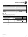
January 8, 2015 - B - Revise Pages 1-4, 2-2 thru 2-12, 2-16, 2-17, 7-2.
31200926
G5-18A, 2505H, 25.5
a
READ THIS FIRST
Modifications
Modifications to this machine may affect compliance with Industry Standards and/or Governmental Regulations.
Any modification must be approved by JLG.
Machine Configuration
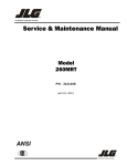
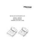
Two configurations of each machine are included in this manual. Determine if machine is equipped with Ultra Low Sulfur
Fuel Decal (1) as indicated below.
• If equipped with the Ultra Low Sulfur decal, all specific references to this machine configuration will be referred to as
Ultra Low Sulfur (ULS) from this point forward.
• If not equipped with the Ultra Low Sulfur decal, all specific references to this machine configuration will be referred to
as Low Sulfur (LS) from this point forward.
1
ULTRA LOW
SULFUR DIESEL
FUEL ONLY
S < 15 mg/kg
1001125387 A
OAH2300
b
G5-18A, 2505H, 25.5
31200926
SECTION CONTENTS
Section
Subject
Section 1
Safety Practices . . . . . . . . . . . . . . . . . . . . . . . . . . . . . . . . . . . . . . . . . . . . . . . . . . . . . . .
1.1
1.2
1.3
1.4
1.5
1.6
1.7
Page
1-1
Introduction . . . . . . . . . . . . . . . . . . . . . . . . . . . . . . . . . . . . . . . . . . . . . . . . . . . . . . . . . .
Disclaimer . . . . . . . . . . . . . . . . . . . . . . . . . . . . . . . . . . . . . . . . . . . . . . . . . . . . . . . . . . .
Operation & Safety Manual . . . . . . . . . . . . . . . . . . . . . . . . . . . . . . . . . . . . . . . . . . . . . .
Do Not Operate Tags . . . . . . . . . . . . . . . . . . . . . . . . . . . . . . . . . . . . . . . . . . . . . . . . . . .
Safety Information . . . . . . . . . . . . . . . . . . . . . . . . . . . . . . . . . . . . . . . . . . . . . . . . . . . . .
Safety Instructions . . . . . . . . . . . . . . . . . . . . . . . . . . . . . . . . . . . . . . . . . . . . . . . . . . . . .
Safety Decals . . . . . . . . . . . . . . . . . . . . . . . . . . . . . . . . . . . . . . . . . . . . . . . . . . . . . . . . .
1-2
1-2
1-2
1-2
1-2
1-3
1-4
Section 2
General Information and Specifications . . . . . . . . . . . . . . . . . . . . . . . . . . . . . . . . . . . .
2-1
2.1
2.2
2.3
2.4
2.5
2.6
2.7
Section 3
Boom
Replacement Parts and Warranty Information . . . . . . . . . . . . . . . . . . . . . . . . . . . . . . . .
Thread Locking Compound . . . . . . . . . . . . . . . . . . . . . . . . . . . . . . . . . . . . . . . . . . . . . .
Torque Charts . . . . . . . . . . . . . . . . . . . . . . . . . . . . . . . . . . . . . . . . . . . . . . . . . . . . . . . .
Specifications. . . . . . . . . . . . . . . . . . . . . . . . . . . . . . . . . . . . . . . . . . . . . . . . . . . . . . . . .
Fluids, Lubricants and Capacities . . . . . . . . . . . . . . . . . . . . . . . . . . . . . . . . . . . . . . . . .
Maintenance Schedule . . . . . . . . . . . . . . . . . . . . . . . . . . . . . . . . . . . . . . . . . . . . . . . . .
Lubrication Schedule . . . . . . . . . . . . . . . . . . . . . . . . . . . . . . . . . . . . . . . . . . . . . . . . . . .
2-2
2-2
2-3
2-14
2-16
2-19
2-22
...........................................................
3-1
Boom System Component Terminology. . . . . . . . . . . . . . . . . . . . . . . . . . . . . . . . . . . . .
Safety Information . . . . . . . . . . . . . . . . . . . . . . . . . . . . . . . . . . . . . . . . . . . . . . . . . . . . .
Two Section Boom System . . . . . . . . . . . . . . . . . . . . . . . . . . . . . . . . . . . . . . . . . . . . . .
Boom Assembly Maintenance . . . . . . . . . . . . . . . . . . . . . . . . . . . . . . . . . . . . . . . . . . . .
Boom Wear Pads . . . . . . . . . . . . . . . . . . . . . . . . . . . . . . . . . . . . . . . . . . . . . . . . . . . . . .
Quick Attach Assembly . . . . . . . . . . . . . . . . . . . . . . . . . . . . . . . . . . . . . . . . . . . . . . . . .
Forks . . . . . . . . . . . . . . . . . . . . . . . . . . . . . . . . . . . . . . . . . . . . . . . . . . . . . . . . . . . . . . .
Boom Prop (If Equipped) . . . . . . . . . . . . . . . . . . . . . . . . . . . . . . . . . . . . . . . . . . . . . . . .
Emergency Boom Lowering Procedure . . . . . . . . . . . . . . . . . . . . . . . . . . . . . . . . . . . . .
Troubleshooting . . . . . . . . . . . . . . . . . . . . . . . . . . . . . . . . . . . . . . . . . . . . . . . . . . . . . . .
3-2
3-3
3-3
3-3
3-9
3-10
3-11
3-12
3-13
3-15
...........................................................
4-1
Operator Cab Component Terminology . . . . . . . . . . . . . . . . . . . . . . . . . . . . . . . . . . . . .
Safety Information . . . . . . . . . . . . . . . . . . . . . . . . . . . . . . . . . . . . . . . . . . . . . . . . . . . . .
Operator Cab . . . . . . . . . . . . . . . . . . . . . . . . . . . . . . . . . . . . . . . . . . . . . . . . . . . . . . . . .
Cab Components . . . . . . . . . . . . . . . . . . . . . . . . . . . . . . . . . . . . . . . . . . . . . . . . . . . . . .
Cab Removal . . . . . . . . . . . . . . . . . . . . . . . . . . . . . . . . . . . . . . . . . . . . . . . . . . . . . . . . .
Cab Installation . . . . . . . . . . . . . . . . . . . . . . . . . . . . . . . . . . . . . . . . . . . . . . . . . . . . . . .
4-2
4-3
4-3
4-3
4-10
4-11
3.1
3.2
3.3
3.4
3.5
3.6
3.7
3.8
3.9
3.10
Section 4
Cab
4.1
4.2
4.3
4.4
4.5
4.6
G5-18A, 2505H, 25.5
i
Section
Subject
Page
Section 5
Axles, Drive Shafts, Wheels and Tires . . . . . . . . . . . . . . . . . . . . . . . . . . . . . . . . . . . . . .
5.1
5.2
5.3
5.4
5.5
5.6
5.7
5.8
5.9
5-1
Axle, Drive Shaft and Wheel Component Terminology . . . . . . . . . . . . . . . . . . . . . . . . .
Safety Information . . . . . . . . . . . . . . . . . . . . . . . . . . . . . . . . . . . . . . . . . . . . . . . . . . . . .
General Information . . . . . . . . . . . . . . . . . . . . . . . . . . . . . . . . . . . . . . . . . . . . . . . . . . . .
Axle Assemblies. . . . . . . . . . . . . . . . . . . . . . . . . . . . . . . . . . . . . . . . . . . . . . . . . . . . . . .
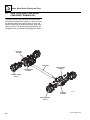
Drive Shafts . . . . . . . . . . . . . . . . . . . . . . . . . . . . . . . . . . . . . . . . . . . . . . . . . . . . . . . . . .
Wheels and Tires . . . . . . . . . . . . . . . . . . . . . . . . . . . . . . . . . . . . . . . . . . . . . . . . . . . . . .
Steering Angle Adjustment. . . . . . . . . . . . . . . . . . . . . . . . . . . . . . . . . . . . . . . . . . . . . . .
Brakes . . . . . . . . . . . . . . . . . . . . . . . . . . . . . . . . . . . . . . . . . . . . . . . . . . . . . . . . . . . . . .
Towing a Disabled Machine . . . . . . . . . . . . . . . . . . . . . . . . . . . . . . . . . . . . . . . . . . . . . .
5-2
5-3
5-3
5-3
5-9
5-10
5-11
5-11
5-12
Section 6
Transmission . . . . . . . . . . . . . . . . . . . . . . . . . . . . . . . . . . . . . . . . . . . . . . . . . . . . . . . . . .
6-1
6.1
6.2
6.3
6.4
6.5
Transmission Assembly Component Terminology . . . . . . . . . . . . . . . . . . . . . . . . . . . . .
Safety Information . . . . . . . . . . . . . . . . . . . . . . . . . . . . . . . . . . . . . . . . . . . . . . . . . . . . .
Transmission Description . . . . . . . . . . . . . . . . . . . . . . . . . . . . . . . . . . . . . . . . . . . . . . . .
Transmission Specifications. . . . . . . . . . . . . . . . . . . . . . . . . . . . . . . . . . . . . . . . . . . . . .
Transmission Replacement . . . . . . . . . . . . . . . . . . . . . . . . . . . . . . . . . . . . . . . . . . . . . .
6-2
6-3
6-3
6-3
6-3
...........................................................
7-1
Introduction . . . . . . . . . . . . . . . . . . . . . . . . . . . . . . . . . . . . . . . . . . . . . . . . . . . . . . . . . .
Engine Cooling System . . . . . . . . . . . . . . . . . . . . . . . . . . . . . . . . . . . . . . . . . . . . . . . . .
Engine Electrical System . . . . . . . . . . . . . . . . . . . . . . . . . . . . . . . . . . . . . . . . . . . . . . . .
Fuel System . . . . . . . . . . . . . . . . . . . . . . . . . . . . . . . . . . . . . . . . . . . . . . . . . . . . . . . . . .
Engine Exhaust System . . . . . . . . . . . . . . . . . . . . . . . . . . . . . . . . . . . . . . . . . . . . . . . . .
Air Cleaner Assembly. . . . . . . . . . . . . . . . . . . . . . . . . . . . . . . . . . . . . . . . . . . . . . . . . . .
Engine Replacement . . . . . . . . . . . . . . . . . . . . . . . . . . . . . . . . . . . . . . . . . . . . . . . . . . .
7-2
7-4
7-7
7-7
7-8
7-10
7-11
Section 8
Hydraulic System . . . . . . . . . . . . . . . . . . . . . . . . . . . . . . . . . . . . . . . . . . . . . . . . . . . . . . .
8-1
Section 7
Engine
7.1
7.2
7.3
7.4
7.5
7.6
7.7
8.1
8.2
8.3
8.4
8.5
8.6
8.7
8.8
8.9
8.10
8.11
8.12
ii
Hydraulic Component Terminology . . . . . . . . . . . . . . . . . . . . . . . . . . . . . . . . . . . . . . . .
Safety Information . . . . . . . . . . . . . . . . . . . . . . . . . . . . . . . . . . . . . . . . . . . . . . . . . . . . .
General Information . . . . . . . . . . . . . . . . . . . . . . . . . . . . . . . . . . . . . . . . . . . . . . . . . . . .
Specifications . . . . . . . . . . . . . . . . . . . . . . . . . . . . . . . . . . . . . . . . . . . . . . . . . . . . . . . . .
Hoses, Tube Lines, Fittings, Etc. . . . . . . . . . . . . . . . . . . . . . . . . . . . . . . . . . . . . . . . . . .
Hydraulic Pressure Diagnosis . . . . . . . . . . . . . . . . . . . . . . . . . . . . . . . . . . . . . . . . . . . .
Hydraulic Schematic . . . . . . . . . . . . . . . . . . . . . . . . . . . . . . . . . . . . . . . . . . . . . . . . . . .
Hydraulic Reservoir . . . . . . . . . . . . . . . . . . . . . . . . . . . . . . . . . . . . . . . . . . . . . . . . . . . .
Hydraulic System Pump. . . . . . . . . . . . . . . . . . . . . . . . . . . . . . . . . . . . . . . . . . . . . . . . .
Front Drive Motor . . . . . . . . . . . . . . . . . . . . . . . . . . . . . . . . . . . . . . . . . . . . . . . . . . . . . .
Control Valves . . . . . . . . . . . . . . . . . . . . . . . . . . . . . . . . . . . . . . . . . . . . . . . . . . . . . . . .
Hydraulic Cylinders . . . . . . . . . . . . . . . . . . . . . . . . . . . . . . . . . . . . . . . . . . . . . . . . . . . .
8-3
8-4
8-4
8-4
8-4
8-5
8-7
8-10
8-11
8-12
8-13
8-26
G5-18A, 2505H, 25.5
Section
Subject
Section 9
Electrical System . . . . . . . . . . . . . . . . . . . . . . . . . . . . . . . . . . . . . . . . . . . . . . . . . . . . . .
9.1
9.2
9.3
9.4
9.5
9.6
9.7
9.8
9.9
9.10
9.11
9.12
9.13
9.14
G5-18A, 2505H, 25.5
Electrical Component Terminology . . . . . . . . . . . . . . . . . . . . . . . . . . . . . . . . . . . . . . . .
Safety Information . . . . . . . . . . . . . . . . . . . . . . . . . . . . . . . . . . . . . . . . . . . . . . . . . . . . .
Fuses and Relays . . . . . . . . . . . . . . . . . . . . . . . . . . . . . . . . . . . . . . . . . . . . . . . . . . . . .
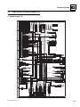
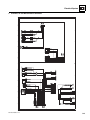
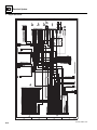
Electrical System Schematics . . . . . . . . . . . . . . . . . . . . . . . . . . . . . . . . . . . . . . . . . . . .
Engine Start Circuit . . . . . . . . . . . . . . . . . . . . . . . . . . . . . . . . . . . . . . . . . . . . . . . . . . . .
Charging Circuit . . . . . . . . . . . . . . . . . . . . . . . . . . . . . . . . . . . . . . . . . . . . . . . . . . . . . . .
Electrical System Components . . . . . . . . . . . . . . . . . . . . . . . . . . . . . . . . . . . . . . . . . . .
Window Wiper/Washer. . . . . . . . . . . . . . . . . . . . . . . . . . . . . . . . . . . . . . . . . . . . . . . . . .
Cab Heater/AC and Fan . . . . . . . . . . . . . . . . . . . . . . . . . . . . . . . . . . . . . . . . . . . . . . . .
Switches, Solenoids and Senders . . . . . . . . . . . . . . . . . . . . . . . . . . . . . . . . . . . . . . . . .
Load Stability Indicator System (2505H & 25.5) . . . . . . . . . . . . . . . . . . . . . . . . . . . . . .
Hand Held Analyzer (2505H & 25.5) . . . . . . . . . . . . . . . . . . . . . . . . . . . . . . . . . . . . . . .
Diagnostic Trouble Codes (DTC) on Ground Module . . . . . . . . . . . . . . . . . . . . . . . . . .
Engine Diagnostic Trouble Code EMR4 . . . . . . . . . . . . . . . . . . . . . . . . . . . . . . . . . . . .
Page
9-1
9-3
9-4
9-4
9-7
9-15
9-17
9-18
9-19
9-21
9-22
9-26
9-32
9-34
9-39
iii
Section
iv
Subject
Page
G5-18A, 2505H, 25.5
Section 1
Safety Practices
Contents
PARAGRAPH
1.1
1.2
1.3
1.4
1.5
1.6
1.7
G5-18A, 2505H, 25.5
TITLE
Introduction . . . . . . . . . . . . . . . . . . . . . . . . . . . . . . . . . . . . . . . . . . . . . . . . . . . . . . .
Disclaimer . . . . . . . . . . . . . . . . . . . . . . . . . . . . . . . . . . . . . . . . . . . . . . . . . . . . . . . .
Operation & Safety Manual. . . . . . . . . . . . . . . . . . . . . . . . . . . . . . . . . . . . . . . . . . .
Do Not Operate Tags. . . . . . . . . . . . . . . . . . . . . . . . . . . . . . . . . . . . . . . . . . . . . . . .
Safety Information. . . . . . . . . . . . . . . . . . . . . . . . . . . . . . . . . . . . . . . . . . . . . . . . . .
1.5.1
Safety Alert System and Signal Words . . . . . . . . . . . . . . . . . . . . . . . . . . .
Safety Instructions . . . . . . . . . . . . . . . . . . . . . . . . . . . . . . . . . . . . . . . . . . . . . . . . .
1.6.1
Personal Hazards . . . . . . . . . . . . . . . . . . . . . . . . . . . . . . . . . . . . . . . . . . .
1.6.2
Equipment Hazards. . . . . . . . . . . . . . . . . . . . . . . . . . . . . . . . . . . . . . . . . .
1.6.3
General Hazards . . . . . . . . . . . . . . . . . . . . . . . . . . . . . . . . . . . . . . . . . . . .
1.6.4
Operational Hazards . . . . . . . . . . . . . . . . . . . . . . . . . . . . . . . . . . . . . . . . .
Safety Decals . . . . . . . . . . . . . . . . . . . . . . . . . . . . . . . . . . . . . . . . . . . . . . . . . . . . . .
PAGE
1-2
1-2
1-2
1-2
1-2
1-2
1-3
1-3
1-3
1-3
1-4
1-4
1-1
Safety Practices
1.1
INTRODUCTION
1.4
DO NOT OPERATE TAGS
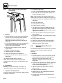
This service manual provides general directions for
accomplishing service and repair procedures. Following
the procedures in this manual will help assure safety and
equipment reliability.
Place Do Not Operate Tags on the ignition key switch and
the steering wheel before attempting to perform any
service or maintenance. Remove key and disconnect
battery leads.
Read, understand and follow the information in this
manual, and obey all locally approved safety practices,
procedures, rules, codes, regulations and laws.
1.5
These instructions cannot cover all details or variations in
the equipment, procedures, or processes described, nor
provide directions for meeting every possible contingency
during operation, maintenance, or testing. When additional
information is desired consult the local JLG Dealer.
Many factors contribute to unsafe conditions: carelessness,
fatigue, overload, inattentiveness, unfamiliarity, even
drugs and alcohol, among others. For optimal safety,
encourage everyone to think, and to act, safely.
SAFETY INFORMATION
To avoid possible death or injury, carefully read,
understand and comply with all safety messages.
In the event of an accident, know where to obtain medical
assistance and how to use a first-aid kit and fire
extinguisher/fire suppression system. Keep emergency
telephone numbers (fire department, ambulance, rescue
squad/paramedics, police department, etc.) nearby. If
working alone, check with another person routinely to
help assure personal safety.
Appropriate service methods and proper repair
procedures are essential for the safety of the individual
doing the work, for the safety of the operator, and for the
safe, reliable operation of the machine. All references to
the right side, left side, front and rear are given from the
operator’s seat looking in a forward direction.
1.5.1
Supplementary information is available from JLG in the
form of Service Bulletins, Service Campaigns, Service
Training Schools, the JLG website, other literature and
through updates to the manual itself.
DANGER indicates an imminently hazardous situation
which, if not avoided, will result in death or serious injury.
1.2
DANGER
WARNING
DISCLAIMER
All information in this manual is based on the latest
product information available at the time of publication.
JLG reserves the right to make changes and
improvements to its products, and to discontinue the
manufacture of any product, at its discretion at any time
without public notice or obligation.
1.3
Safety Alert System and Signal Words
WARNING indicates a potentially hazardous situation
which, if not avoided, could result in death or serious
injury.
CAUTION
OPERATION & SAFETY MANUAL
The mechanic must not operate the machine until the
Operation & Safety Manual has been read and
understood, training has been accomplished and
operation of the machine has been completed under the
supervision of an experienced and qualified operator.
CAUTION indicates a potentially hazardous situation
which, if not avoided, may result in minor or moderate
injury.
An Operation & Safety Manual is supplied with each
machine and must be kept in the manual holder located
in the cab. In the event that the Operation & Safety
Manual is missing, consult the local JLG Dealer
before proceeding.
1-2
G5-18A, 2505H, 25.5
Safety Practices
1.6
SAFETY INSTRUCTIONS
Following are general safety statements to consider
BEFORE performing maintenance procedures on the
telehandler. Additional statements related to specific
tasks and procedures are located throughout this manual
and are listed prior to any work instructions to provide
safety information before the potential of a hazard occurs.
For all safety messages, carefully read, understand and
follow the instructions BEFORE proceeding.
1.6.1
Personal Hazards
PERSONAL SAFETY GEAR: Wear all the protective
clothing and personal safety gear necessary to perform
the job safely. This might include heavy gloves, safety
glasses or goggles, filter mask or respirator, safety shoes
or a hard hat.
LIFTING: NEVER lift a heavy object without the help of at
least one assistant or a suitable sling and hoist.
1.6.2
Equipment Hazards
LIFTING OF EQUIPMENT: Before using any lifting
equipment (chains, slings, brackets, hooks, etc.), verify
that it is of the proper capacity, in good working order, and
is properly attached.
NEVER stand or otherwise become positioned under a
suspended load or under raised equipment. The load or
equipment could fall or tip.
DO NOT use a hoist, jack or jack stands only to support
equipment. Always support equipment with the proper
capacity blocks or stands properly rated for the load.
1.6.3
General Hazards
SOLVENTS: Only use approved solvents that are known
to be safe for use.
HOUSEKEEPING: Keep the work area and operator’s
cab clean, and remove all hazards (debris, oil, tools, etc.).
FIRST AID: Immediately clean, dress and report all injuries
(cuts, abrasions, burns, etc.), no matter how minor the
injury may seem. Know the location of a First Aid Kit, and
know how to use it.
CLEANLINESS: Wear eye protection and clean all
components with a high-pressure or steam cleaner
before attempting service.
When removing hydraulic components, plug hose ends
and connections to prevent excess leakage and
contamination. Place a suitable catch basin beneath the
machine to capture fluid run-off.
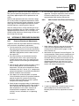
It is good practice to avoid pressure-washing electrical/
electronic components. In the event pressure-washing
the machine is needed, ensure machine is shut down
before pressure-washing. Should pressure-washing be
utilized to wash areas containing electrical/electronic
components, it is recommended a maximum pressure of
750 psi (52 bar) at a minimum distance of 12 in (30,5 cm)
away from these components. If electrical/electronic
components are sprayed, spraying must not be direct
and for brief time periods to avoid heavy saturation,
Check and obey all Federal, State and/or Local
regulations regarding waste storage, disposal
and recycling.
HAND TOOLS: Always use the proper tool for the job;
keep tools clean and in good working order, and use
special service tools only as recommended.
G5-18A, 2505H, 25.5
1-3
Safety Practices
1.6.4
Operational Hazards
ENGINE: Stop the engine before performing any service
unless specifically instructed otherwise.
VENTILATION: Avoid prolonged engine operation in
enclosed areas without adequate ventilation.
SOFT SURFACES AND SLOPES: NEVER work on a
machine that is parked on a soft surface or slope. The
machine must be on a hard level surface, with the wheels
blocked before performing any service.
FLUID TEMPERATURE: NEVER work on a machine
when engine, cooling or hydraulic systems are hot. Hot
components and fluids can cause severe burns. Allow
systems to cool before proceeding.
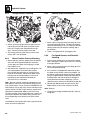
FLUID PRESSURE: Before loosening any hydraulic or
diesel fuel component, hose or tube, turn the engine
OFF. Wear heavy, protective gloves and eye protection.
NEVER check for leaks using any part of your body; use
a piece of cardboard or wood instead. If injured, seek
medical attention immediately. Diesel fluid leaking under
pressure can explode. Hydraulic fluid and diesel fuel
leaking under pressure can penetrate the skin, cause
infection, gangrene and other serious personal injury.
Engine fuel lines are pressurized. DO NOT attempt
repairs unless specific training has been completed.
Refer to the engine manufacturers’ manual for specific
details concerning the fuel system.
Relieve all pressure before disconnecting any
component, part, line or hose. Slowly loosen parts and
allow release of residual pressure before removing any
part or component. Before starting the engine or applying
pressure, use components, parts, hoses and pipes that
are in good condition, connected properly and are
tightened to the proper torque. Capture fluid in an
appropriate container and dispose of in accordance with
prevailing environmental regulations.
NEVER drain or store fluids in an open container. Engine
fuel and hydraulic fluid are flammable and can cause a
fire and/or explosion.
DO NOT mix gasoline or alcohol with diesel fuel. The
mixture can cause an explosion.
PRESSURE TESTING: When conducting any test, only
use test equipment that is correctly calibrated and in good
condition. Use the correct equipment in the proper
manner, and make changes or repairs as indicated by the
test procedure to achieve the desired result.
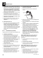
LEAVING MACHINE: Lower the forks or attachment to
the ground before leaving the machine.
TIRES: Always keep tires inflated to the proper pressure
to help prevent tipover. DO NOT over-inflate tires.
NEVER use mismatched tire types, sizes or ply ratings.
Always use matched sets according to machine
specifications.
MAJOR COMPONENTS: Never alter, remove, or
substitute any items such as counterweights, tires,
batteries or other items that may reduce or affect the
overall weight or stability of the machine.
BATTERY: DO NOT charge a frozen battery.Charging
a frozen battery may cause it to explode. Allow the
battery to thaw before jump-starting or connecting a
battery charger.
1.7
SAFETY DECALS
Check that all safety decals are present and readable on
the machine. Refer to the Operation & Safety Manual
supplied with machine for information.
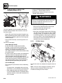
COOLANT SYSTEM CAP: The cooling system is under
pressure, and escaping coolant can cause severe burns
and eye injury. To prevent personal injury, NEVER
remove the coolant system cap while the cooling system
is hot. Wear safety glasses. Turn the coolant system cap
to allow pressure to escape before removing the cap
completely. Failure to follow the safety practices could
result in death or serious injury.
FLUID FLAMABILTITY: DO NOT service the fuel or
hydraulic systems near an open flame, sparks or smoking
materials.
Properly disconnect battery prior to servicing the fuel or
hydraulic systems.
1-4
G5-18A, 2505H, 25.5
Section 2
General Information and Specifications
Contents
PARAGRAPH
2.1
2.2
2.3
2.4
2.5
2.6
2.7
G5-18A, 2505H, 25.5
TITLE
Replacement Parts and Warranty Information . . . . . . . . . . . . . . . . . . . . . . . . . . .
Thread Locking Compound . . . . . . . . . . . . . . . . . . . . . . . . . . . . . . . . . . . . . . . . . .
Torque Charts . . . . . . . . . . . . . . . . . . . . . . . . . . . . . . . . . . . . . . . . . . . . . . . . . . . . .
2.3.1
SAE Fastener Torque Chart . . . . . . . . . . . . . . . . . . . . . . . . . . . . . . . . . . .
2.3.2
Metric Fastener Torque Chart . . . . . . . . . . . . . . . . . . . . . . . . . . . . . . . . . .
2.3.3
Hydraulic Hose Torque Chart . . . . . . . . . . . . . . . . . . . . . . . . . . . . . . . . . .
Specifications . . . . . . . . . . . . . . . . . . . . . . . . . . . . . . . . . . . . . . . . . . . . . . . . . . . . .
2.4.1
Travel Speed. . . . . . . . . . . . . . . . . . . . . . . . . . . . . . . . . . . . . . . . . . . . . . .
2.4.2
Hydraulic Cylinder Performance Specifications . . . . . . . . . . . . . . . . . . . .
2.4.3
Electrical System. . . . . . . . . . . . . . . . . . . . . . . . . . . . . . . . . . . . . . . . . . . .
2.4.4
Engine Performance Specifications . . . . . . . . . . . . . . . . . . . . . . . . . . . . .
2.4.5
Tires . . . . . . . . . . . . . . . . . . . . . . . . . . . . . . . . . . . . . . . . . . . . . . . . . . . . .
Fluids, Lubricants and Capacities . . . . . . . . . . . . . . . . . . . . . . . . . . . . . . . . . . . . .
2.5.1
Fluids. . . . . . . . . . . . . . . . . . . . . . . . . . . . . . . . . . . . . . . . . . . . . . . . . . . . .
2.5.2
Capacities . . . . . . . . . . . . . . . . . . . . . . . . . . . . . . . . . . . . . . . . . . . . . . . . .
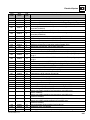
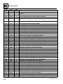
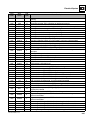
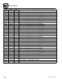
Maintenance Schedule . . . . . . . . . . . . . . . . . . . . . . . . . . . . . . . . . . . . . . . . . . . . . .
2.6.1
10,1st 50 & 50 Hour Maintenance Schedule. . . . . . . . . . . . . . . . . . . . . . .
2.6.2
1st 250, 250 & 500 Hour Maintenance Schedule . . . . . . . . . . . . . . . . . . .
2.6.3
1000 & 1500 Hour Maintenance Schedule . . . . . . . . . . . . . . . . . . . . . . . .
Lubrication Schedule . . . . . . . . . . . . . . . . . . . . . . . . . . . . . . . . . . . . . . . . . . . . . . .
2.7.1
250 Hour Lubrication Schedule. . . . . . . . . . . . . . . . . . . . . . . . . . . . . . . . .
PAGE
2-2
2-2
2-3
2-3
2-9
2-13
2-14
2-14
2-14
2-14
2-15
2-15
2-16
2-16
2-18
2-19
2-19
2-20
2-21
2-22
2-22
2-1
General Information and Specifications
2.1
REPLACEMENT PARTS AND
WARRANTY INFORMATION
2.2
THREAD LOCKING COMPOUND
JLG P/N Loctite® ND Industries
Description
0100011
242TM
Vibra-TITETM121
Medium Strength (Blue)
1001095650
243TM
Vibra-TITETM122
Medium Strength (Blue)
0100019
271TM
Vibra-TITETM140
High Strength (Red)
0100071
262TM
Vibra-TITETM131
Medium - High Strength (Red)
Loctite® 243TM can be substituted in place of Loctite® 242TM. VibraTITETM 122 can be substituted in place of Vibra-TITETM 121.
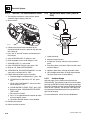
1
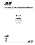
MY8350
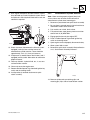
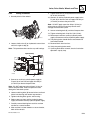
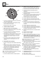
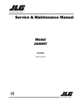
Before ordering parts or initiating service inquiries, make
note of the machine serial number. The machine serial
number plate (1) is located as indicated in the figure.
Note: The replacement of any part on this machine with
any other than JLG authorized replacement parts can
adversely affect the performance, durability, or safety of
the machine, and will void the warranty. JLG disclaims
liability for any claims or damages, whether regarding
property damage, personal injury or death arising out of
the use of unauthorized replacement parts.
A warranty registration form must be filled out by the JLG
Dealer.
Registration activates the warranty period and helps to
assure that warranty claims are promptly processed to
guarantee full warranty service.
2-2
G5-18A, 2505H, 25.5
General Information and Specifications
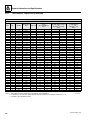
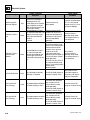
2.3
TORQUE CHARTS
2.3.1
SAE Fastener Torque Chart
Values for Zinc Yellow Chromate Fasteners (Ref 4150707)
SAE GRADE 5 BOLTS & GRADE 2 NUTS
Tensile
Stress Area
Clamp
Load
Torque
(Dry)
Torque
Lubricated
Size
TPI
Bolt Dia
In
Sq In
LB
IN-LB
[N.m]
IN-LB
[N.m]
4
40
0.1120
0.00604
380
8
0.9
6
0.7
6
48
0.1120
0.00661
420
9
1.0
7
0.8
32
0.1380
0.00909
580
16
1.8
12
1.4
Torque
(Loctite® 242TM or 271TM
or Vibra-TITETM
111 or 140)
IN-LB
[N.m]
Torque
(Loctite® 262TM or
Vibra-TITETM 131)
IN-LB
[N.m]
40
0.1380
0.01015
610
18
2.0
13
1.5
32
0.1640
0.01400
900
30
3.4
22
2.5
36
0.1640
0.01474
940
31
3.5
23
2.6
24
0.1900
0.01750
1120
43
4.8
32
3.5
32
0.1900
0.02000
1285
49
5.5
36
4
20
0.2500
0.0318
2020
96
10.8
75
9
105
12
28
0.2500
0.0364
2320
120
13.5
86
10
135
15
In
Sq In
LB
FT-LB
[N.m]
FT-LB
[N.m]
FT-LB
[N.m]
FT-LB
[N.m]
18
0.3125
0.0524
3340
17
23
13
18
19
26
16
22
24
0.3125
0.0580
3700
19
26
14
19
21
29
17
23
3/8
16
0.3750
0.0775
4940
30
41
23
31
35
48
28
38
24
0.3750
0.0878
5600
35
47
25
34
40
54
32
43
7/16
14
0.4375
0.1063
6800
50
68
35
47
55
75
45
61
8
10
1/4
5/16
20
0.4375
0.1187
7550
55
75
40
54
60
82
50
68
1/2
13
0.5000
0.1419
9050
75
102
55
75
85
116
68
92
20
0.5000
0.1599
10700
90
122
65
88
100
136
80
108
9/16
12
0.5625
0.1820
11600
110
149
80
108
120
163
98
133
18
0.5625
0.2030
12950
120
163
90
122
135
184
109
148
11
0.6250
0.2260
14400
150
203
110
149
165
224
135
183
18
0.6250
0.2560
16300
170
230
130
176
190
258
153
207
5/8
3/4
7/8
1
1 1/8
1 1/4
1 3/8
1 1/2
10
0.7500
0.3340
21300
260
353
200
271
285
388
240
325
16
0.7500
0.3730
23800
300
407
220
298
330
449
268
363
9
0.8750
0.4620
29400
430
583
320
434
475
646
386
523
14
0.8750
0.5090
32400
470
637
350
475
520
707
425
576
8
1.0000
0.6060
38600
640
868
480
651
675
918
579
785
12
1.0000
0.6630
42200
700
949
530
719
735
1000
633
858
7
1.1250
0.7630
42300
800
1085
600
813
840
1142
714
968
12
1.1250
0.8560
47500
880
1193
660
895
925
1258
802
1087
7
1.2500
0.9690
53800
1120
1518
840
1139
1175
1598
1009
1368
12
1.2500
1.0730
59600
1240
1681
920
1247
1300
1768
1118
1516
6
1.3750
1.1550
64100
1460
1979
1100
1491
1525
2074
1322
1792
12
1.3750
1.3150
73000
1680
2278
1260
1708
1750
2380
1506
2042
6
1.5000
1.4050
78000
1940
2630
1460
1979
2025
2754
1755
2379
12
1.5000
1.5800
87700
2200
2983
1640
2224
2300
3128
1974
2676
NOTES: 1. THESE TORQUE VALUES DO NOT APPLY TO CADMIUM PLATED FASTENERS
5000059K
2. ALL TORQUE VALUES ARE STATIC TORQUE MEASURED PER STANDARD AUDIT METHODS TOLERANCE = ±10%
3. * ASSEMBLY USES HARDENED WASHER
G5-18A, 2505H, 25.5
2-3
General Information and Specifications
2.3.1
SAE Fastener Torque Chart (Continued)
Values for Zinc Yellow Chromate Fasteners (Ref 4150707)
SAE GRADE 8 (HEX HD) BOLTS & GRADE 8 NUTS*
Tensile Stress
Clamp Load
Area
Size
TPI
Bolt Dia
In
Sq In
4
40
0.1120
0.00604
48
0.1120
0.00661
32
0.1380
0.00909
40
0.1380
0.01015
6
8
LB
Torque
(Dry or Loctite® 263)
K=0.20
IN-LB
[N.m]
Torque
(Loctite® 242TM or 271TM or
Vibra-TITETM 111 or 140)
K=0.18
IN-LB
[N.m]
Torque
(Loctite® 262TM or
Vibra-TITETM 131)
K=0.15
IN-LB
[N.m]
32
0.1640
0.01400
36
0.1640
0.01474
1320
43
5
24
0.1900
0.01750
1580
60
7
32
0.1900
0.02000
1800
68
8
20
0.2500
0.0318
2860
143
16
129
28
0.2500
0.0364
3280
164
19
148
17
In
Sq In
LB
FT-LB
[N.m]
FT-LB
[N.m]
FT-LB
[N.m]
18
0.3125
0.0524
4720
25
35
20
25
20
25
24
0.3125
0.0580
5220
25
35
25
35
20
25
3/8
16
0.3750
0.0775
7000
45
60
40
55
35
50
24
0.3750
0.0878
7900
50
70
45
60
35
50
7/16
14
0.4375
0.1063
9550
70
95
65
90
50
70
20
0.4375
0.1187
10700
80
110
70
95
60
80
1/2
13
0.5000
0.1419
12750
105
145
95
130
80
110
20
0.5000
0.1599
14400
120
165
110
150
90
120
9/16
12
0.5625
0.1820
16400
155
210
140
190
115
155
18
0.5625
0.2030
18250
170
230
155
210
130
175
11
0.6250
0.2260
20350
210
285
190
260
160
220
18
0.6250
0.2560
23000
240
325
215
290
180
245
10
0.7500
0.3340
30100
375
510
340
460
280
380
16
0.7500
0.3730
33600
420
570
380
515
315
430
9
0.8750
0.4620
41600
605
825
545
740
455
620
14
0.8750
0.5090
45800
670
910
600
815
500
680
8
1.0000
0.6060
51500
860
1170
770
1045
645
875
12
1.0000
0.6630
59700
995
1355
895
1215
745
1015
7
1.1250
0.7630
68700
1290
1755
1160
1580
965
1310
12
1.1250
0.8560
77000
1445
1965
1300
1770
1085
1475
7
1.2500
0.9690
87200
1815
2470
1635
2225
1365
1855
12
1.2500
1.0730
96600
2015
2740
1810
2460
1510
2055
10
1/4
5/16
5/8
3/4
7/8
1
1 1/8
1 1/4
1 3/8
1 1/2
15
6
1.3750
1.1550
104000
2385
3245
2145
2915
1785
2430
12
1.3750
1.3150
118100
2705
3680
2435
3310
2030
2760
6
1.5000
1.4050
126500
3165
4305
2845
3870
2370
3225
12
1.5000
1.5800
142200
3555
4835
3200
4350
2665
3625
NOTES: 1. THESE TORQUE VALUES DO NOT APPLY TO CADMIUM PLATED FASTENERS
5000059K
2. ALL TORQUE VALUES ARE STATIC TORQUE MEASURED PER STANDARD AUDIT METHODS TOLERANCE = ±10%
3. * ASSEMBLY USES HARDENED WASHER
2-4
G5-18A, 2505H, 25.5
General Information and Specifications
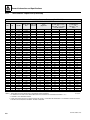
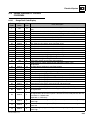
2.3.1
SAE Fastener Torque Chart (Continued)
Values for Magni Coating Fasteners (Ref 4150701)
SAE GRADE 5 BOLTS & GRADE 2 NUTS
Torque
(Dry)
K=0.17
Tensile Stress
Clamp Load
Area
Torque
(Loctite® 242TM or 271TM or
Vibra-TITETM 111 or 140)
K=0.16
IN-LB
[N.m]
Torque
(Loctite® 262TM or
Vibra-TITETM 131)
K=0.15
IN-LB
[N.m]
Size
TPI
Bolt Dia
In
Sq In
LB
IN-LB
[N.m]
4
40
0.1120
0.00604
380
7
0.8
48
0.1120
0.00661
420
8
0.9
32
0.1380
0.00909
580
14
1.5
40
0.1380
0.01015
610
14
1.6
8
32
0.1640
0.01400
900
25
2.8
36
0.1640
0.01474
940
26
2.9
10
24
0.1900
0.01750
1120
36
4.1
32
0.1900
0.02000
1285
42
4.7
20
0.2500
0.0318
2020
86
9.7
80
9
28
0.2500
0.0364
2320
99
11.1
95
11
In
Sq In
LB
FT-LB
[N.m]
FT-LB
[N.m]
FT-LB
18
0.3125
0.0524
3340
15
20
14
19
15
20
24
0.3125
0.0580
3700
15
20
15
21
15
20
16
0.3750
0.0775
4940
25
35
25
34
25
34
24
0.3750
0.0878
5600
30
40
28
38
25
34
14
0.4375
0.1063
6800
40
55
40
54
35
48
20
0.4375
0.1187
7550
45
60
44
60
40
54
13
0.5000
0.1419
9050
65
90
60
82
55
75
20
0.5000
0.1599
10700
75
100
71
97
65
88
9/16
12
0.5625
0.1820
11600
90
120
87
118
80
109
18
0.5625
0.2030
12950
105
145
97
132
90
122
5/8
11
0.6250
0.2260
14400
130
175
120
163
115
156
18
0.6250
0.2560
16300
145
195
136
185
125
170
3/4
10
0.7500
0.3340
21300
225
305
213
290
200
272
6
1/4
5/16
3/8
7/16
1/2
7/8
1
1 1/8
1 1/4
1 3/8
1 1/2
[N.m]
16
0.7500
0.3730
23800
255
345
238
324
225
306
9
0.8750
0.4620
29400
365
495
343
466
320
435
14
0.8750
0.5090
32400
400
545
378
514
355
483
8
1.0000
0.6060
38600
545
740
515
700
480
653
12
1.0000
0.6630
42200
600
815
563
765
530
721
7
1.1250
0.7630
42300
675
920
635
863
595
809
12
1.1250
0.8560
47500
755
1025
713
969
670
911
7
1.2500
0.9690
53800
955
1300
897
1219
840
1142
12
1.2500
1.0730
59600
1055
1435
993
1351
930
1265
6
1.3750
1.1550
64100
1250
1700
1175
1598
1100
1496
12
1.3750
1.3150
73000
1420
1930
1338
1820
1255
1707
6
1.5000
1.4050
78000
1660
2260
1560
2122
1465
1992
12
1.5000
1.5800
87700
1865
2535
1754
2385
1645
2237
NOTES: 1. THESE TORQUE VALUES DO NOT APPLY TO CADMIUM PLATED FASTENERS
5000059K
2. ALL TORQUE VALUES ARE STATIC TORQUE MEASURED PER STANDARD AUDIT METHODS TOLERANCE = ±10%
3. * ASSEMBLY USES HARDENED WASHER
G5-18A, 2505H, 25.5
2-5
General Information and Specifications
2.3.1
SAE Fastener Torque Chart (Continued)
Values for Magni Coating Fasteners (Ref 4150701)
SAE GRADE 8 (HEX HD) BOLTS & GRADE 8 NUTS*
Tensile Stress
Clamp Load
Area
Size
TPI
Bolt Dia
In
Sq In
4
40
0.1120
0.00604
48
0.1120
0.00661
32
0.1380
0.00909
40
0.1380
0.01015
6
8
LB
Torque
(Dry or Loctite® 263)
K=0.17
IN-LB
[N.m]
Torque
(Loctite® 242TM or 271TM or
Vibra-TITETM 111 or 140)
K=0.16
IN-LB
[N.m]
Torque
(Loctite® 262TM or
Vibra-TITETM 131)
K=0.15
IN-LB
[N.m]
32
0.1640
0.01400
36
0.1640
0.01474
1320
37
4
24
0.1900
0.01750
1580
51
6
32
0.1900
0.02000
1800
58
7
20
0.2500
0.0318
2860
122
14
114
28
0.2500
0.0364
3280
139
16
131
15
In
Sq In
LB
FT-LB
[N.m]
FT-LB
[N.m]
FT-LB
[N.m]
18
0.3125
0.0524
4720
20
25
20
25
20
25
24
0.3125
0.0580
5220
25
35
20
25
20
25
16
0.3750
0.0775
7000
35
50
35
50
35
50
24
0.3750
0.0878
7900
40
55
40
55
35
50
7/16
14
0.4375
0.1063
9550
60
80
55
75
50
70
20
0.4375
0.1187
10700
65
90
60
80
60
80
1/2
13
0.5000
0.1419
12750
90
120
85
115
80
110
20
0.5000
0.1599
14400
100
135
95
130
90
120
9/16
12
0.5625
0.1820
16400
130
175
125
170
115
155
18
0.5625
0.2030
18250
145
195
135
185
130
175
11
0.6250
0.2260
20350
180
245
170
230
160
220
18
0.6250
0.2560
23000
205
280
190
260
180
245
10
0.7500
0.3340
30100
320
435
300
410
280
380
16
0.7500
0.3730
33600
355
485
335
455
315
430
9
0.8750
0.4620
41600
515
700
485
660
455
620
14
0.8750
0.5090
45800
570
775
535
730
500
680
8
1.0000
0.6060
51500
730
995
685
930
645
875
12
1.0000
0.6630
59700
845
1150
795
1080
745
1015
10
1/4
5/16
3/8
5/8
3/4
7/8
1
1 1/8
1 1/4
1 3/8
1 1/2
13
7
1.1250
0.7630
68700
1095
1490
1030
1400
965
1310
12
1.1250
0.8560
77000
1225
1665
1155
1570
1085
1475
7
1.2500
0.9690
87200
1545
2100
1455
1980
1365
1855
12
1.2500
1.0730
96600
1710
2325
1610
2190
1510
2055
6
1.3750
1.1550
104000
2025
2755
1905
2590
1785
2430
12
1.3750
1.3150
118100
2300
3130
2165
2945
2030
2760
6
1.5000
1.4050
126500
2690
3660
2530
3440
2370
3225
12
1.5000
1.5800
142200
3020
4105
2845
3870
2665
3625
NOTES: 1. THESE TORQUE VALUES DO NOT APPLY TO CADMIUM PLATED FASTENERS
5000059K
2. ALL TORQUE VALUES ARE STATIC TORQUE MEASURED PER STANDARD AUDIT METHODS TOLERANCE = ±10%
3. * ASSEMBLY USES HARDENED WASHER
2-6
G5-18A, 2505H, 25.5
General Information and Specifications
2.3.1
SAE Fastener Torque Chart (Continued)
Values for Magni Coating Fasteners (Ref 4150701)
SOCKET HEAD CAP SCREWS
Tensile Stress Clamp Load
Area
See Note 4
Size
TPI
Bolt Dia
In
Sq In
4
40
0.1120
0.00604
48
0.1120
0.00661
32
0.1380
0.00909
40
0.1380
0.01015
6
8
10
1/4
5/16
3/8
7/16
1/2
9/16
5/8
3/4
7/8
1
1 1/8
1 1/4
1 3/8
1 1/2
LB
Torque
(Dry) K=0.17
IN-LB
[N.m]
Torque
(Loctite® 242TM or 271TM or
Vibra-TITETM 111 or 140) or
Precoat® 85 K=0.16
IN-LB
[N.m]
Torque
(Loctite® 262TM or
Vibra-TITETM 131)
K=0.15
IN-LB
[N.m]
32
0.1640
0.01400
36
0.1640
0.01474
24
0.1900
0.01750
32
0.1900
0.02000
20
0.2500
0.0318
2860
122
14
114
13
28
0.2500
0.0364
3280
139
16
131
15
In
Sq In
LB
FT-LB
[N.m]
FT-LB
[N.m]
FT-LB
18
0.3125
0.0524
4720
20
25
20
25
20
25
24
0.3125
0.0580
5220
25
35
20
25
20
25
16
0.3750
0.0775
7000
35
50
35
50
35
50
24
0.3750
0.0878
7900
40
55
40
55
35
50
14
0.4375
0.1063
9550
60
80
55
75
50
70
20
0.4375
0.1187
10700
65
90
60
80
60
80
13
0.5000
0.1419
12750
90
120
85
115
80
110
20
0.5000
0.1599
14400
100
135
95
130
90
120
12
0.5625
0.1820
16400
130
175
125
170
115
155
18
0.5625
0.2030
18250
145
195
135
185
130
175
11
0.6250
0.2260
20350
180
245
170
230
160
220
18
0.6250
0.2560
23000
205
280
190
260
180
245
10
0.7500
0.3340
30100
320
435
300
415
280
380
[N.m]
16
0.7500
0.3730
33600
355
485
335
455
315
430
9
0.8750
0.4620
41600
515
700
485
660
455
620
14
0.8750
0.5090
45800
570
775
535
730
500
680
8
1.0000
0.6060
51500
730
995
685
930
645
875
12
1.0000
0.6630
59700
845
1150
795
1080
745
1015
7
1.1250
0.7630
68700
1095
1490
1030
1400
965
1310
12
1.1250
0.8560
77000
1225
1665
1155
1570
1085
1475
7
1.2500
0.9690
87200
1545
2100
1455
1980
1365
1855
12
1.2500
1.0730
96600
1710
2325
1610
2190
1510
2055
6
1.3750
1.1550
104000
2025
2755
1905
2590
1785
2430
12
1.3750
1.3150
118100
2300
3130
2165
2945
2030
2760
6
1.5000
1.4050
126500
2690
3660
2530
3440
2370
3225
12
1.5000
1.5800
142200
3020
4105
2845
3870
2665
3625
NOTES: 1. THESE TORQUE VALUES DO NOT APPLY TO CADMIUM PLATED FASTENERS
5000059K
2. ALL TORQUE VALUES ARE STATIC TORQUE MEASURED PER STANDARD AUDIT METHODS TOLERANCE = ±10%
3. * ASSEMBLY USES HARDENED WASHER
4. CLAMP LOAD LISTED FOR SHCS IS SAME AS GRADE 8 OR CLASS 10.9 AND DOES NOT REPRESENT FULL STRENGTH CAPABILITY OF SHCS.
IF HIGHER LOAD IS REQUIRED, ADDITIONAL TESTING IS REQUIRED.
G5-18A, 2505H, 25.5
2-7
General Information and Specifications
2.3.1
SAE Fastener Torque Chart (Continued)
Values for Zinc Yellow Chromate Fasteners (Ref 4150707)*
SOCKET HEAD CAP SCREWS
Tensile Stress Clamp Load
Area
See Note 4
Size
TPI
Bolt Dia
In
Sq In
4
40
0.1120
0.00604
48
0.1120
0.00661
32
0.1380
0.00909
40
0.1380
0.01015
6
8
Torque
(Dry) K=0.17
LB
IN-LB
[N.m]
Torque
(Loctite® 242TM or 271TM or
Vibra-TITETM 111 or 140) or
Precoat® 85 K=0.16
IN-LB
[N.m]
Torque
(Loctite® 262TM or
Vibra-TITETM 131)
K=0.15
IN-LB
[N.m]
32
0.1640
0.01400
36
0.1640
0.01474
24
0.1900
0.01750
32
0.1900
0.02000
20
0.2500
0.0318
2860
122
14
114
28
0.2500
0.0364
3280
139
16
131
15
In
Sq In
LB
FT-LB
[N.m]
FT-LB
[N.m]
FT-LB
[N.m]
18
0.3125
0.0524
4720
20
25
20
25
20
25
24
0.3125
0.0580
5220
25
35
20
25
20
25
16
0.3750
0.0775
7000
35
50
35
50
35
50
24
0.3750
0.0878
7900
40
55
40
55
35
50
7/16
14
0.4375
0.1063
9550
60
80
55
75
50
70
20
0.4375
0.1187
10700
65
90
60
80
60
80
1/2
13
0.5000
0.1419
12750
90
120
85
115
80
110
20
0.5000
0.1599
14400
100
135
95
130
90
120
9/16
12
0.5625
0.1820
16400
130
175
125
170
115
155
18
0.5625
0.2030
18250
145
195
135
185
130
175
11
0.6250
0.2260
20350
180
245
170
230
160
220
18
0.6250
0.2560
23000
205
280
190
260
180
245
10
0.7500
0.3340
30100
320
435
300
415
280
380
16
0.7500
0.3730
33600
355
485
335
455
315
430
9
0.8750
0.4620
41600
515
700
485
660
455
620
14
0.8750
0.5090
45800
570
775
535
730
500
680
8
1.0000
0.6060
51500
730
995
685
930
645
875
12
1.0000
0.6630
59700
845
1150
795
1080
745
1015
10
1/4
5/16
3/8
5/8
3/4
7/8
1
1 1/8
1 1/4
1 3/8
1 1/2
13
7
1.1250
0.7630
68700
1095
1490
1030
1400
965
1310
12
1.1250
0.8560
77000
1225
1665
1155
1570
1085
1475
7
1.2500
0.9690
87200
1545
2100
1455
1980
1365
1855
12
1.2500
1.0730
96600
1710
2325
1610
2190
1510
2055
6
1.3750
1.1550
104000
2025
2755
1905
2590
1785
2430
12
1.3750
1.3150
118100
2300
3130
2165
2945
2030
2760
6
1.5000
1.4050
126500
2690
3660
2530
3440
2370
3225
12
1.5000
1.5800
142200
3020
4105
2845
3870
2665
3625
NOTES: 1. THESE TORQUE VALUES DO NOT APPLY TO CADMIUM PLATED FASTENERS
5000059K
2. ALL TORQUE VALUES ARE STATIC TORQUE MEASURED PER STANDARD AUDIT METHODS TOLERANCE = ±10%
3. * ASSEMBLY USES HARDENED WASHER
4. CLAMP LOAD LISTED FOR SHCS IS SAME AS GRADE 8 OR CLASS 10.9 AND DOES NOT REPRESENT FULL STRENGTH CAPABILITY OF SHCS.
IF HIGHER LOAD IS REQUIRED, ADDITIONAL TESTING IS REQUIRED.
2-8
G5-18A, 2505H, 25.5
General Information and Specifications
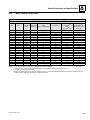
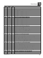
2.3.2
Metric Fastener Torque Chart
Values for Zinc Yellow Chromate Fasteners (Ref 4150707)*
CLASS 8.8 METRIC (HEX/SOCKET HEAD) BOLTS CLASS 8 METRIC NUTS
Tensile Stress Clamp Load
Area
See Note 4
Torque
(Dry or Loctite® 263TM)
Torque (Lub)
Torque
(Loctite® 262TM or
271TM or
Vibra-TITETM 131)
Torque
(Loctite® 242TM or
271TM or Vibra-TITETM
111 or 141)
Size
Pitch
Sq mm
KN
[N.m]
[N.m]
[N.m]
3
0.5
5.03
2.19
1.3
1.0
1.2
1.4
3.5
0.6
6.78
2.95
2.1
1.6
1.9
2.3
4
0.7
8.78
3.82
3.1
2.3
2.8
3.4
5
0.8
14.20
6.18
6.2
4.6
5.6
6.8
6
1
20.10
8.74
11
7.9
9.4
12
7
1
28.90
12.6
18
13
16
19
8
1.25
36.60
15.9
26
19
23
28
10
1.5
58.00
25.2
50
38
45
55
12
1.75
84.30
36.7
88
66
79
97
14
2
115
50.0
140
105
126
154
16
2
157
68.3
219
164
197
241
18
2.5
192
83.5
301
226
271
331
20
2.5
245
106.5
426
320
383
469
22
2.5
303
132.0
581
436
523
639
24
3
353
153.5
737
553
663
811
27
3
459
199.5
1080
810
970
1130
30
3.5
561
244.0
1460
1100
1320
1530
33
3.5
694
302.0
1990
1490
1790
2090
36
4
817
355.5
2560
1920
2300
2690
42
4.5
1120
487.0
4090
3070
3680
4290
NOTES: 1. THESE TORQUE VALUES DO NOT APPLY TO CADMIUM PLATED FASTENERS
5000059K
2. ALL TORQUE VALUES ARE STATIC TORQUE MEASURED PER STANDARD AUDIT METHODS TOLERANCE = ±10%
3. * ASSEMBLY USES HARDENED WASHER
4. CLAMP LOAD LISTED FOR SHCS IS SAME AS GRADE 8 OR CLASS 10.9 AND DOES NOT REPRESENT FULL STRENGTH CAPABILITY OF SHCS.
IF HIGHER LOAD IS REQUIRED, ADDITIONAL TESTING IS REQUIRED.
G5-18A, 2505H, 25.5
2-9
General Information and Specifications
2.3.2
Metric Fastener Torque Chart (Continued)
Values for Zinc Yellow Chromate Fasteners (Ref 4150707)*
CLASS 10.9 METRIC (HEX HEAD) BOLTS,
CLASS 10 METRIC NUTS CLASS 12.9 SOCKET HEAD CAP SCREWS M3 - M5*
Size
Pitch
3
0.5
Clamp Load
See Note 4
Torque
(Dry or Loctite® 263TM)
K=0.20
Torque
(Lub or Loctite®
242TM or 271TM or
Vibra-TITETM 111 or 140)
K=0.18
Torque
(Loctite® 262TM or
Vibra-TITETM 131)
K=0.15
Sq mm
KN
[N.m]
[N.m]
[N.m]
5.03
3.13
Tensile Stress
Area
3.5
0.6
6.78
4.22
4
0.7
8.78
5.47
5
0.8
14.20
8.85
6
1
20.10
12.5
7
1
28.90
18.0
25
23
19
8
1.25
36.60
22.8
37
33
27
10
1.5
58.00
36.1
70
65
55
12
1.75
84.30
52.5
125
115
95
14
2
115
71.6
200
180
150
16
2
157
97.8
315
280
235
18
2.5
192
119.5
430
385
325
20
2.5
245
152.5
610
550
460
22
2.5
303
189.0
830
750
625
24
3
353
222.0
1065
960
800
27
3
459
286.0
1545
1390
1160
30
3.5
561
349.5
2095
1885
1575
33
3.5
694
432.5
2855
2570
2140
36
4
817
509.0
3665
3300
2750
42
4.5
1120
698.0
5865
5275
4395
NOTES: 1. THESE TORQUE VALUES DO NOT APPLY TO CADMIUM PLATED FASTENERS
5000059K
2. ALL TORQUE VALUES ARE STATIC TORQUE MEASURED PER STANDARD AUDIT METHODS TOLERANCE = ±10%
3. * ASSEMBLY USES HARDENED WASHER
4. CLAMP LOAD LISTED FOR SHCS IS SAME AS GRADE 8 OR CLASS 10.9 AND DOES NOT REPRESENT FULL STRENGTH CAPABILITY OF SHCS.
IF HIGHER LOAD IS REQUIRED, ADDITIONAL TESTING IS REQUIRED.
2-10
G5-18A, 2505H, 25.5
General Information and Specifications
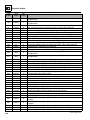
2.3.2
Metric Fastener Torque Chart (Continued)
Values for Magni Coated Fasteners (Ref 4150701)*
CLASS 8.8 METRIC (HEX/SOCKET HEAD) BOLTS CLASS 8 METRIC NUTS
Tensile Stress
Area
Clamp Load
See Note 4
Torque
(Dry or Loctite® 263TM)
K=0.17
Torque
(Lub or Loctite®
TM
242 or 271TM or
Vibra-TITETM 111 or 140)
K=0.16
Torque
(Loctite® 262TM or
Vibra-TITETM 131)
K=0.15
Size
Pitch
Sq mm
KN
[N.m]
[N.m]
[N.m]
3
0.5
5.03
2.19
1.1
1.1
1.0
3.5
0.6
6.78
2.95
1.8
1.7
1.5
4
0.7
8.78
3.82
2.6
2.4
2.3
5
0.8
14.20
6.18
5.3
4.9
4.6
6
1
20.10
8.74
9
8.4
7.9
7
1
28.90
12.6
15
14
13
8
1.25
36.60
15.9
22
20
19
10
1.5
58.00
25.2
43
40
38
12
1.75
84.30
36.7
75
70
66
14
2
115
50.0
119
110
105
16
2
157
68.3
186
175
165
18
2.5
192
83.5
256
240
225
20
2.5
245
106.5
362
340
320
22
2.5
303
132.0
494
465
435
24
3
353
153.5
627
590
555
27
3
459
199.5
916
860
810
30
3.5
561
244.0
1245
1170
1100
33
3.5
694
302.0
1694
1595
1495
36
4
817
355.5
2176
2050
1920
42
4.5
1120
487.0
3477
3275
3070
NOTES: 1. THESE TORQUE VALUES DO NOT APPLY TO CADMIUM PLATED FASTENERS
5000059K
2. ALL TORQUE VALUES ARE STATIC TORQUE MEASURED PER STANDARD AUDIT METHODS TOLERANCE = ±10%
3. * ASSEMBLY USES HARDENED WASHER
4. CLAMP LOAD LISTED FOR SHCS IS SAME AS GRADE 8 OR CLASS 10.9 AND DOES NOT REPRESENT FULL STRENGTH CAPABILITY OF SHCS.
IF HIGHER LOAD IS REQUIRED, ADDITIONAL TESTING IS REQUIRED.
G5-18A, 2505H, 25.5
2-11
General Information and Specifications
2.3.2
Metric Fastener Torque Chart (Continued)
Values for Magni Coated Fasteners (Ref 4150701)*
CLASS 10.9 METRIC (HEX HEAD) BOLTS CLASS 10 METRIC NUTS,
CLASS 12.9 SOCKET HEAD CAP SCREWS M6 AND ABOVE*
Size
Pitch
3
0.5
Clamp Load See
Note 4
Torque
(Dry or Loctite® 263TM)
K=0.17
Torque
(Lub or Loctite®
242TM or 271TM or
Vibra-TITETM 111 or 140)
K=0.18
Torque
(Loctite® 262TM or
Vibra-TITETM 131)
K=0.15
Sq mm
KN
[N.m]
[N.m]
[N.m]
5.03
3.13
Tensile Stress
Area
3.5
0.6
6.78
4.22
4
0.7
8.78
5.47
5
0.8
14.20
8.85
6
1
20.10
12.5
13
12
11
7
1
28.90
18.0
21
20
19
8
1.25
36.60
22.8
31
29
27
10
1.5
58.00
36.1
61
58
55
12
1.75
84.30
52.5
105
100
95
14
2
115
71.6
170
160
150
16
2
157
97.8
265
250
235
18
2.5
192
119.5
365
345
325
20
2.5
245
152.5
520
490
460
22
2.5
303
189.0
705
665
625
24
3
353
222.0
905
850
800
27
3
459
286.0
1315
1235
1160
30
3.5
561
349.5
1780
1680
1575
33
3.5
694
432.5
2425
2285
2140
36
4
817
509.0
3115
2930
2750
42
4.5
1120
698.0
4985
4690
4395
NOTES: 1. THESE TORQUE VALUES DO NOT APPLY TO CADMIUM PLATED FASTENERS
5000059K
2. ALL TORQUE VALUES ARE STATIC TORQUE MEASURED PER STANDARD AUDIT METHODS TOLERANCE = ±10%
3. * ASSEMBLY USES HARDENED WASHER
4. CLAMP LOAD LISTED FOR SHCS IS SAME AS GRADE 8 OR CLASS 10.9 AND DOES NOT REPRESENT FULL STRENGTH CAPABILITY OF SHCS.
IF HIGHER LOAD IS REQUIRED, ADDITIONAL TESTING IS REQUIRED.
2-12
G5-18A, 2505H, 25.5
General Information and Specifications
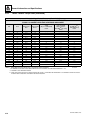
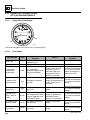
2.3.3
Hydraulic Hose Torque Chart
O-Ring Face Seal & JIC Torque Chart
Torque Wrench:
1. Identify the appropriate application and refer to the
above chart for the correct torque value.
2. If equipped, lubricate o-ring with hydraulic oil. Hand
tighten the swivel nut until no lateral movement of
the swivel nut can be detected. Average hand torque
is 3 lb-ft (4 Nm).
Size
ORFS
JIC
Flats Method
4
13 lb-ft
(18 Nm)
13 lb-ft
(18 Nm)
1.5 to 1.75
6
23 lb-ft
(31 Nm)
23 lb-ft
(31 Nm)
1 to 1.5
8
40 lb-ft
(54 Nm)
40 lb-ft
(54 Nm)
1.5 to 1.75
4. Torque wrench must be held at the center of the grip.
Apply constant force until it clicks.
10
60 lb-ft
(81 Nm)
60 lb-ft
(81 Nm)
1.5 to 1.75
12
136 lb-ft
(100 Nm)
136 lb-ft
(100 Nm)
5. After connection has been properly tightened, mark
a straight line across connecting parts indicating that
connection has been properly tightened.
1.0 to 1.5
16
115 lb-ft
(156 Nm)
115 lb-ft
(156 Nm)
0.75 to 1.0
20
170 lb-ft
(230 Nm)
170 lb-ft
(230 Nm)
0.75 to 1.0
24
200 lb-ft
(271 Nm)
200 lb-ft
(271 Nm)
0.75 to 1.0
32
N/A
270 lb-ft
(366 Nm)
0.75 to 1.0
Note: By definition the “Flats Method” will contain some
variance. Use the “Flats Method” only when accessibility
with a torque wrench is not possible.
G5-18A, 2505H, 25.5
3. Use the double wrench method while tightening to
avoid hose twist.
Flats Method:
1. If equipped, lubricate o-ring with hydraulic oil. Hand
tighten the swivel nut until no lateral movement of
the swivel nut can be detected. Average hand torque
is 3 lb-ft (4 Nm).
2. Mark a dot on one of swivel nut flats and another dot
in line on hex of adapter it’s connecting to.
3. Use double wrench method while tightening to avoid
hose twist.
4. After connection has been properly tightened, mark
a straight line across the connecting parts, not
covering dots indicating that connection has been
properly tightened.
2-13
General Information and Specifications
2.4
SPECIFICATIONS
2.4.1
Travel Speed
Tires
Approximate Speed
12–16.50 (305/70D16.5)
15 mph (24 km/h)
14–17.50 (355/70D17.5)
17 mph (27 km/h)
10.5–18
17 mph (27 km/h)
2.4.2
Hydraulic Cylinder Performance Specifications
Note: Machine with no load, engine at full throttle, hydraulic oil above 15.6° C (60° F) minimum, engine at
operating temperature.
Approximate Times (sec.)
Function
ANSI
CE & AUS
Boom Extend (Boom Level)
6.7
6.7
Boom Retract
3.8
3.5
Boom Lift
6.8
6.6
Boom Lower
4.6
8.2
Quick Attach—UP
2.0
1.8
Quick Attach—DOWN
2.5
2.3
2.4.3
Electrical System
Note: Refer to Section 9.3, “Fuses and Relays,” for more information.
Battery
Type, Rating
12 BCI, Negative (-) Ground, Maintenance Free
Cold Cranking Amps @ 0° F (-18° C)
950
Cranking Amps @ 32° F (-18° C)
1190
Reserve Capacity Minutes @ 25 Amps
185
Group/Series
Alternator
2-14
Group 31
14V, 95 Amps
G5-18A, 2505H, 25.5
General Information and Specifications
2.4.4
Engine Performance Specifications
Description
Engine Make/Model
Deutz TD L4
Displacement
177 in³ (2.9 L)
Low Idle
975 - 1075 rpm
High Idle
2300 - 2400 rpm
Horsepower
74 HP (55 kW) @ 2300 rpm
Peak Torque
192 lb-ft (260 Nm) @ 1800 rpm
Fuel Delivery
Fuel Injection
Air Cleaner
2.4.5
Dry Type, Replaceable Primary and Safety Elements
Tires
Note: Standard wheel lug nut torque is 220 lb-ft (300 Nm).
Note: Pressures for Foam filled tires are for initial fill ONLY.
Size
Tire Type
Minimum Ply/
Star Rating
12–16.50 (305/70D16.5)
Duraforce
DT
Bias 12 Ply
14–17.50 (355/70D17.5)
Outrigger
Bias 14 Ply
MPT-01 TL
Bias 16 Ply
10.5–18
33x12–20
G5-18A, 2505H, 25.5
Fill Type
Pressure
Pneumatic
80 psi (5,5 bar)
Foam - Approximately 220 lb (100 kg)
Pneumatic
70 psi (4,8 bar)
Foam - Approximately 220 lb (100 kg)
Pneumatic
87 psi (6,0 bar)
Non–Marking (White)
2-15
General Information and Specifications
2.5
FLUIDS, LUBRICANTS AND CAPACITIES
2.5.1
Fluids
a. If Equipped for ULS
Ambient Temperature Range
Compartment or
System
Engine Crankcase
Axle Differential and
Wheel End
Type and Classification
Viscosities
°F
°C
Min
Max
Min
Max
SAE 0W-30
-20
0
-29
-18
SAE 5W-30
-15
70
-26
21
SAE 10W-30
-9
70
-22
21
SAE 15W-40
5
120
-15
49
MobilFluid 424
10W-30
0
104
-20
40
MobilFluid LT
75W-80
-40
0
-40
-20
SAE 140
50
122
10
50
80W-140
85W-140
14
122
-10
50
SAE90
SAE90LS
32
104
0
40
80W-90
85W-90
-4
104
-20
40
75W-90
-40
104
-20
40
75W
-40
50
-40
10
10W-30
0
104
-20
40
-40
0
-40
20
API CJ-4 Plus
API GL-4 with LS Additives
or
API GL5 with LS Additives
MobilFluid 424
Hydraulic System
Exxon Univis HVI 26
Brake System
MobilFluid 424
10W-30
15
120
-10
49
Boom Wear Pad Grease
Mystik Tetrimoly
NLGI Grade 2
-4
104
-20
40
Cylinder and Axle Grease
Multipurpose Grease
NLGI Grade 2
-22
104
-30
40
Boom Chain Lubricant
Engine Coolant
Schaffer 200S Silver Streak
Ethylene Glycol
and Water
50/50 Mix
Standard
60/40 Mix
Cold Weather
#2 Diesel
B5 Biodiesel fuels
Fuel
Blend of #1 diesel and #2 diesel fuels
("winterized" #2)
Ultra Low
Sulfur
(S ≤ 15 mg/
kg)
Standard
Cold Weather
B5 Biodiesel with Winter Conditioner
Air Conditioning
Refrigerant R-134-a
Tetrafluoroethane
Note: Friction Modifier may be added to front axle differentials, refer to Section 2.5.2, “Capacities.”
2-16
G5-18A, 2505H, 25.5
General Information and Specifications
b. If Equipped for LS
Ambient Temperature Range
Compartment or
System
Engine Crankcase
Axle Differential and
Wheel End
Type and Classification
Viscosities
°F
°C
Min
Max
Min
Max
SAE 0W-30
-20
0
-29
-18
SAE 5W-30
-15
70
-26
21
SAE 10W-30
-9
70
-22
21
SAE 15W-40
5
120
-15
49
MobilFluid 424
10W-30
0
104
-20
40
MobilFluid LT
75W-80
-40
0
-40
-20
SAE 140
50
122
10
50
80W-140 85W140
14
122
-10
50
SAE90
SAE90LS
32
104
0
40
80W-90
85W-90
-4
104
-20
40
75W-90
-40
104
-20
40
75W
-40
50
-40
10
10W-30
0
104
-20
40
-40
0
-40
20
API CI-4 Plus
API GL-4 with LS Additives
or
API GL5 with LS Additives
MobilFluid 424
Hydraulic System
Exxon Univis HVI 26
Brake System
MobilFluid 424
10W-30
15
120
-10
49
Boom Wear Pad Grease
Mystik Tetrimoly
NLGI Grade 2
-4
104
-20
40
Cylinder and Axle Grease
Multipurpose Grease
NLGI Grade 2
-22
104
-30
40
Boom Chain Lubricant
Engine Coolant
Schaffer 200S Silver Streak
Ethylene Glycol
and Water
50/50 Mix
Standard
60/40 Mix
Cold Weather
#2 Diesel
Standard
B5 Biodiesel fuels
Fuel
Blend of #1 diesel and #2 diesel fuels
("winterized" #2)
Low Sulfur
(S ≤ 500 mg/kg)
Cold Weather
B5 Biodiesel with Winter Conditioner
Air Conditioning
Refrigerant R-134-a
Tetrafluoroethane
Note: Friction Modifier may be added to front axle differentials, refer to Section 2.5.2, “Capacities.”
G5-18A, 2505H, 25.5
2-17
General Information and Specifications
2.5.2
Capacities
Engine Crankcase Oil
Capacity w/Filter Change
9.6 qt (9,1 L)
Fuel Tank
Capacity
24 gal (91 L)
Cooling System
System Capacity
14 qt (13,2 L)
Hydraulic System
System Capacity
24 gal (91 L)
Reservoir Capacity to Full Mark
16 gal (61 L)
Auxiliary Hydraulic Circuit Max Flow
18.7 gpm (71 lpm)
Brake System
System Capacity
0.7 qt (0,7 L)
Axles
Differential Housing Capacity
Friction Modifier (Front Axle Only)
3.5 qt (3,3 L)
5.4 oz (0,16 L)
Wheel End Capacity
24 oz (0,7 L)
Front Axle Drop Box
21 oz (0,6 L)
Air Conditioning System (if equipped)
System Capacity
2-18
1.7 lb (771 g)
G5-18A, 2505H, 25.5
General Information and Specifications
2.6
2.6.1
MAINTENANCE SCHEDULE
10,1st 50 & 50 Hour Maintenance Schedule
EVERY
10
Check Fuel
Level
Check Engine
Oil Level
Check Hydraulic
Oil Level
Check Tire
Condition &
Pressure
Additional
Checks Section 8
Check
Air Filter
Check
Battery
Check Brake
Fluid Level
1st
50
LB/F
T (N
m)
Check Wheel
Lug Nut
Torque
EVERY
50
Drain Fuel/
Water
Separator
Check Engine
Coolant Level
Check Washer
Fluid Level
(if equipped)
OAH2341
G5-18A, 2505H, 25.5
2-19
General Information and Specifications
2.6.2
1st 250, 250 & 500 Hour Maintenance Schedule
1st
250
Change Axle
Differential Oil
Change Wheel
End Oil
Change Front
Axle Drop
Box Oil
EVERY
250
Check Axle
Differential Oil
Level
Check Wheel
End Oil Levels
Check Enclosed
Cab Air Filter
(if equipped)
Lubrication
Schedule
Check Front
Axle Drop
Box Oil Level
Check
Fan Belt
Check Boom
Wear Pads
EVERY
500
LB/F
T (N
m)
Change Engine
Oil and Filter
Change
Air Filter
Elements
Change Fuel Filter
(if equipped for LS)
Check LSI
Calibration
(CE & AUS)
Check Wheel
Lug Nut
Torque
OAH2211
2-20
G5-18A, 2505H, 25.5
General Information and Specifications
2.6.3
1000 & 1500 Hour Maintenance Schedule
EVERY
1000
Change Axle
Differential Oil
Change Wheel
End Oil
Change
Transmission
Filter
Change Fuel Filter
(if equipped for ULS)
Change Front
Axle Drop
Box Oil
Change
Hydraulic
Fluid & Filters
Check
Hydraulic Tank
Cap
EVERY
1500
Change
Engine Coolant
OAH2220
G5-18A, 2505H, 25.5
2-21
General Information and Specifications
2.7
2.7.1
LUBRICATION SCHEDULE
250 Hour Lubrication Schedule
EVERY
250
OAL1980
2-22
G5-18A, 2505H, 25.5
Section 3
Boom
Contents
PARAGRAPH
3.1
3.2
3.3
3.4
3.5
3.6
3.7
3.8
3.9
3.10
G5-18A, 2505H, 25.5
TITLE
Boom System Component Terminology . . . . . . . . . . . . . . . . . . . . . . . . . . . . . . . .
Safety Information. . . . . . . . . . . . . . . . . . . . . . . . . . . . . . . . . . . . . . . . . . . . . . . . . .
Two Section Boom System . . . . . . . . . . . . . . . . . . . . . . . . . . . . . . . . . . . . . . . . . .
3.3.1
Boom System Description. . . . . . . . . . . . . . . . . . . . . . . . . . . . . . . . . . . . .
Boom Assembly Maintenance . . . . . . . . . . . . . . . . . . . . . . . . . . . . . . . . . . . . . . . .
3.4.1
Complete Boom Removal . . . . . . . . . . . . . . . . . . . . . . . . . . . . . . . . . . . . .
3.4.2
Complete Boom Installation . . . . . . . . . . . . . . . . . . . . . . . . . . . . . . . . . . .
3.4.3
Second Boom Section Removal . . . . . . . . . . . . . . . . . . . . . . . . . . . . . . . .
3.4.4
Second Boom Section Installation . . . . . . . . . . . . . . . . . . . . . . . . . . . . . .
3.4.5
Extend/Retract Cylinder Removal . . . . . . . . . . . . . . . . . . . . . . . . . . . . . . .
3.4.6
Extend/Retract Cylinder Installation . . . . . . . . . . . . . . . . . . . . . . . . . . . . .
Boom Wear Pads. . . . . . . . . . . . . . . . . . . . . . . . . . . . . . . . . . . . . . . . . . . . . . . . . . .
3.5.1
Wear Pad Inspection. . . . . . . . . . . . . . . . . . . . . . . . . . . . . . . . . . . . . . . . .
3.5.2
Wear Pad Installation and Lubrication . . . . . . . . . . . . . . . . . . . . . . . . . . .
3.5.3
Boom Wear Pad Lubrication . . . . . . . . . . . . . . . . . . . . . . . . . . . . . . . . . . .
Quick Attach Assembly . . . . . . . . . . . . . . . . . . . . . . . . . . . . . . . . . . . . . . . . . . . . .
3.6.1
Quick Attach Assembly Removal . . . . . . . . . . . . . . . . . . . . . . . . . . . . . . .
3.6.2
Quick Attach Assembly Installation . . . . . . . . . . . . . . . . . . . . . . . . . . . . . .
Forks . . . . . . . . . . . . . . . . . . . . . . . . . . . . . . . . . . . . . . . . . . . . . . . . . . . . . . . . . . . .
Boom Prop (If Equipped) . . . . . . . . . . . . . . . . . . . . . . . . . . . . . . . . . . . . . . . . . . . .
3.8.1
Prop Installation . . . . . . . . . . . . . . . . . . . . . . . . . . . . . . . . . . . . . . . . . . . .
3.8.2
Prop Removal . . . . . . . . . . . . . . . . . . . . . . . . . . . . . . . . . . . . . . . . . . . . . .
Emergency Boom Lowering Procedure . . . . . . . . . . . . . . . . . . . . . . . . . . . . . . . .
3.9.1
Equipment and Supplies Required . . . . . . . . . . . . . . . . . . . . . . . . . . . . . .
3.9.2
Lowering Procedure . . . . . . . . . . . . . . . . . . . . . . . . . . . . . . . . . . . . . . . . .
Troubleshooting . . . . . . . . . . . . . . . . . . . . . . . . . . . . . . . . . . . . . . . . . . . . . . . . . . .
PAGE
3-2
3-3
3-3
3-3
3-3
3-3
3-4
3-5
3-6
3-7
3-9
3-9
3-9
3-9
3-10
3-10
3-10
3-11
3-11
3-12
3-12
3-12
3-13
3-13
3-14
3-15
3-1
Boom
3.1
BOOM SYSTEM COMPONENT
TERMINOLOGY
To understand the safety, operation and maintenance
information presented in this section, it is necessary that
the operator/mechanic be familiar with the names and
locations of the major assemblies of the boom system.
The following illustration identifies the components that
are referred to throughout this section.
COMPENSATING
CYLINDER
FIRST
BOOM
SECTION
SECOND
BOOM
SECTION
PIVOT PIN
LIFT/LOWER
CYLINDER
TILT
CYLINDER
EXTEND/RETRACT
CYLINDER
AUXILIARY HYDRAULIC
QUICK CONNECTS
MY8380
3-2
G5-18A, 2505H, 25.5
Boom
3.2
SAFETY INFORMATION
3.4.1
Complete Boom Removal
1. Remove any attachment from quick attach assembly.
WARNING
DO NOT service the machine without following all
safety precautions as outlined in the “Safety Practices”
section of this manual.
3.3
TWO SECTION BOOM SYSTEM
2. Park machine on a hard, level surface.
3. Fully retract boom, lower boom, place transmission
control lever in (N) NEUTRAL.
4. Engage park brake and shut engine OFF.
5. Place a Do Not Operate Tag on both ignition key
switch and steering wheel.
6. Allow system fluids to cool.
3.3.1
Boom System Description
Boom operates via an interchange among electrical,
hydraulic and mechanical systems. Components
involved include joystick, tilt cylinder, extend/retract
cylinder, lift/lower cylinder, compensating cylinder,
electronic sensors, various pivots, supporting hardware
and other components.
7. Remove the quick attach assembly. Refer to Section
3.6.1, “Quick Attach Assembly Removal.”
Note: The use of two slings will allow for better stability.
1
WARNING
2
NEVER weld or drill the boom unless approved in
writing by the manufacturer. The structural integrity of
the boom will be impaired if subjected to any repair
involving welding or drilling.
3.4
BOOM ASSEMBLY MAINTENANCE
Boom assembly consists of first and second section
booms and supporting hardware.
Note: Before removing boom or boom section, carriage
or any other attachment must be removed from quick
attach assembly.
Before beginning, conduct a visual inspection of machine
and work area, and review task about to be undertaken.
Read, understand and follow these instructions.
MY8570
8. Start machine and raise boom to position that will
allow for pin (1) to clear frame for removal.
9. Remove the lock bolt (2) and pin (1) from
compensating cylinder.
During service of boom, perform following:
1. Check wear pads. (Refer to Section 3.5.1, “Wear
Pad Inspection.”)
2. Apply grease at all lubrication points (grease fittings).
(Refer to Section 2.7, “Lubrication Schedule.”)
3. Check for proper operation by operating all boom
functions through their full ranges of motion
several times.
Depending on your particular circumstance, the following
procedures explain removal/installation of complete
boom or removal/installation of individual boom sections.
G5-18A, 2505H, 25.5
3-3
Boom
16. Lower boom to a level position and place a suitable
support under rear of boom. Reposition slings to
each end of boom.
3
17. Remove capscrew (5) and locknut (6) securing boom
pivot pin (7) and remove boom pivot pin.
4
MY8580
10. Lower the boom to a position that allows for the
removal of rod end pin (3) connecting lift/lower
cylinder to boom.
11. Support boom by placing a sling(s) around boom
head. Support lift/lower cylinder and remove lock
bolt (4) and rod end pin (3). Lower lift/lower cylinder
onto frame rails.
18. Lift complete boom off machine and set on level
ground or supports being careful not to damage
tubes on bottom of boom.
3.4.2
Complete Boom Installation
Note: Lubrication of boom wear surfaces with grease is
recommended to keep boom wear surfaces lubricated
properly. Lubrication of boom wear surfaces is also
recommended when machine is stored, to help
prevent rusting. Refer to Section 2.5, “Fluids, Lubricants
and Capacities.”
1. Park machine on a hard, level surface.
2. Place transmission control lever in (N) NEUTRAL.
12. Properly disconnect battery.
13. Label and disconnect tilt and (if equipped) auxiliary
hydraulic hoses attached to machine at tubes on top
of boom. Plug and cap hose ends to prevent dirt and
debris from entering hydraulic system.
14. Label and disconnect extend/retract hydraulic
hoses at tubes on side of boom. Plug and cap
hose ends to prevent dirt and debris from entering
hydraulic system.
3. Engage park brake and shut engine OFF.
4. Place a Do Not Operate Tag on both ignition key
switch and steering wheel.
5. Allow system fluids to cool.
Note: Grease the boom pivot bore, compensating
cylinder rod ends, lift/lower cylinder rod end and pins
before installing.
15. If equipped, disconnect the LSI boom proximity
sensor at rear of first boom section.
6. Balance boom assembly using suitable slings and
carefully guide the boom into position for attachment
to frame.
Note: Tag or identify each hose to the corresponding
fitting it was removed from.
7. Align frame pivot bore with the boom assembly pivot
bore. Install boom pivot pin (7)
8. Install capscrew (5). Apply locking compound and
torque locknut (6) to 66 lb-ft (90 Nm).
5
6
9. With sling still in place, install rod end of the lift/lower
cylinder, pin (3) and lock bolt (4). Apply locking
compound and torque to 66 lb-ft (90 Nm).
7
Note: Raising boom up or down with sling may be
necessary so boom, compensating and lift/lower cylinder
bores can be aligned for easier pin installation.
MY8590
3-4
G5-18A, 2505H, 25.5
Boom
10. Uncap and reconnect extend/retract cylinder fittings
and plugs to extend/retract cylinder tubes and
tighten until wrench-tight. Mark fitting, then torque to
specification. Refer to Section 2.3.3, “Hydraulic
Hose Torque Chart.”
11. Uncap and reconnect tilt hoses and (if equipped)
auxiliary hoses. Attach both sets to their appropriate
fittings until wrench-tight. Mark fitting, then torque to
specification. Refer to Section 2.3.3, “Hydraulic
Hose Torque Chart.”
3.4.3
Second Boom Section Removal
1. Remove any attachment from quick attach assembly.
2. Be sure there is enough room in front of machine to
allow boom sections to be removed.
3. Park machine on a hard, level surface.
4. Fully retract boom, lower boom, place transmission
control lever in (N) NEUTRAL.
5. Engage park brake and shut engine OFF.
6. Place a Do Not Operate Tag on both ignition key
switch and steering wheel.
7. Properly disconnect battery.
8. Open engine cover. Allow system fluids to cool.
8
9. Remove quick attach assembly. Refer to Section
3.6.1, “Quick Attach Assembly Removal.”
9
10. Label and disconnect tilt hoses and (if equipped)
auxiliary hydraulic hoses attached to machine at
boom head. Plug and cap hose ends to prevent dirt
and debris from entering hydraulic system.
Note: Tag or identify each hose to corresponding fitting
it was removed from.
11. Label and disconnect extend/retract hydraulic tubes
on extend/retract cylinder at the rear of boom. Plug
and cap hose ends to prevent dirt and debris from
entering hydraulic system.
MY8570
12. Raise boom to height that allows for installation of
compensating cylinder, pin (8) and lock bolt (9).
Apply locking compound and torque to
66 lb-ft (90 Nm).
12. Remove top and side wear pads from rear of second
boom section.
Note: Tag each pad, backing plate, shim and bolts from
each location.
13. Adjust and shim each wear pad as needed.
14. Start engine and operate all boom functions several
times to bleed any air out of hydraulic system.
15. Check for fluid leaks.
10
16. Check the hydraulic fluid level in tank and add fluid
as required.
17. Clean up all debris, hydraulic fluid, etc., in, on, near
and around the machine.
11
18. Close and secure engine cover.
19. Remove Do Not Operate Tags from both ignition key
switch and the steering wheel.
20. Install previously removed attachment to quick
attach assembly.
MY1960
13. Remove lock bolt and nut (10) from rear of
extend/retract cylinder.
14. Remove extend/retract cylinder mounting pin (11).
15. Support front of boom by placing a sling behind
boom head.
G5-18A, 2505H, 25.5
3-5
Boom
16. Pull second boom section out of first boom section
approximately 6 in to 8 in (15 cm to 20 cm).
17. Pull tilt hoses and (if equipped) auxiliary hydraulic
hoses through rear of boom.
18. Remove top, side and bottom wear pads from front
of first boom section.
Note: Tag each pad, backing plate, shim and bolts from
each location.
3.4.4
Second Boom Section Installation
Note: Lubrication of boom wear surfaces with grease is
recommended to keep boom wear surfaces lubricated
properly. Lubrication of boom wear surfaces is also
recommended when machine is stored, to help
prevent rusting. Refer to Section 2.5, “Fluids, Lubricants
and Capacities.”
Note: The use of two slings will allow for better stability.
1. If previously removed, install extend/retract cylinder
into rear of second boom section. Pin and clip barrel
end of cylinder in place.
19. Pull second boom section halfway out of first boom
section, reposition sling(s), balancing second boom
section and remove from first boom section.
2. Install wear pads, shims and bolts to their proper
location at front inside of first boom section.
DO NOT tighten wear pads at this time.
20. Place second boom section on suitable stands to
begin tear down.
3. Feed the tilt cylinder hoses and if equipped, the
auxiliary hoses through the channel above the
extend/retract cylinder.
21. Inspect boom and welds. Consult local JLG Dealer if
structural damage is detected.
22. Inspect hoses, hardware, wear pads, mounting
points and other components visible with first boom
section. Replace any item if damaged.
4. Using suitable sling(s), balance second boom
section, lift and carefully guide boom into place.
23. Inspect all wear pads for wear. (Refer to Section
3.5.1, “Wear Pad Inspection.”)
10
11
MY1960
5. Install extend/retract cylinder mounting pin (11).
6. Install lock bolt and nut (10) at rear of
extend/retract cylinder.
7. Install wear pads, shims and bolts previously
removed from rear of second boom section.
DO NOT tighten the wear pads at this time.
8. Uncap and reconnect extend/retract cylinder fittings
and plugs from extend/retract cylinder tubes and
tighten until wrench-tight. Mark fitting, then torque to
specification. Refer to Section 2.3.3, “Hydraulic
Hose Torque Chart.”
9. Uncap and reconnect tilt hoses and (if equipped)
auxiliary hoses. Attach both sets to their appropriate
fittings until wrench-tight. Mark fitting, then torque to
specification. Refer to Section 2.3.3, “Hydraulic
Hose Torque Chart.”
10. Adjust and shim each wear pad as needed.
11. Properly connect battery.
3-6
G5-18A, 2505H, 25.5
Boom
12. Start engine and operate all boom functions several
times to bleed any air out of hydraulic system. Check
for fluid leaks. Check hydraulic fluid level in tank and
add fluid as required.
3.4.5
Extend/Retract Cylinder Removal
Note: Boom must be properly aligned (level) with
access hole at rear of frame to allow removal of
extend/retract cylinder barrel mounting pin.
1. Remove any attachment from quick attach assembly.
12
2. Be sure there is enough room in front of machine to
allow boom sections to be removed.
3. Park machine on a hard, level surface.
4. Fully retract boom, lower boom, place transmission
control lever in (N) NEUTRAL.
5. Engage park brake and shut engine OFF.
6. Place a Do Not Operate Tag on both ignition key
switch and steering wheel.
MY2000
13. Check clearance (12) between the tilt hoses (and if
equipped) auxiliary hoses and the front of the
extend/retract cylinder trunnion. There should be
approximately 1/2 in. (12,7 mm) of clearance.
7. Open engine cover and properly disconnect battery.
8. Allow system fluids to cool.
9. Remove the quick attach assembly. Refer to Section
3.6.1, “Quick Attach Assembly Removal.”
14. If adjustment is needed, loosen the tilt tubes (and if
equipped) auxiliary tubes. Move tubes to achieve the
proper clearance.
15. Clean up all debris, hydraulic fluid, etc., in, on, near
and around the machine.
13
16. Close and secure the engine cover.
17. Remove Do Not Operate Tags from both ignition key
switch and the steering wheel.
18. Install previously removed attachment to quick
attach assembly.
MY2680
10. Remove cylinder rod eye retaining clips and
mounting pin (13) at side of second boom section.
G5-18A, 2505H, 25.5
3-7
Boom
15
18
14
19
17
MY2670
16
MY8610
11. Loosen and remove hose clamps and cover
plate (14) from rear of boom assembly.
12. Remove any miscellaneous parts such as mirror if
they will interfere with removal of cylinder.
13. Label and disconnect tilt and (if equipped) auxiliary
hydraulic hoses attached to machine on top of
boom (15). Plug and cap hose ends to prevent dirt
and debris from entering hydraulic system.
14. Loosen and remove both extend/retract cylinder
tubes (16) at rear of first boom section. Plug
tube ends to prevent dirt and debris from entering
hydraulic system.
15. Loosen and remove both fittings (17) from bottom of
extend/retract cylinder barrel. Plug openings in
extend/retract cylinder barrel.
16. Loosen and remove hardware (18) securing on
cylinder barrel mounting pin.
17. Remove cylinder barrel mounting pin (19). Note
location of spacers and washers.
18. Attach a sling or other suitable lifting device to
extend/retract cylinder and carefully pull cylinder free
from machine through rear of boom/chassis.
Note: The tilt hoses and if equipped, auxiliary
hoses may need to be moved during removal of
extend/retract cylinder.
3-8
G5-18A, 2505H, 25.5
Boom
3.4.6
Extend/Retract Cylinder Installation
1. Carefully install the extend/retract cylinder into rear
of boom using a suitable sling.
2. Line up barrel end of cylinder with pin bores on first
boom section.
Note: The tilt hoses and (if equipped) the auxiliary
hoses may need to be moved during installation of the
extend/retract cylinder.
3. Install mounting pin (19), spacers and washers
through frame access hole on chassis and first boom
section bore and cylinder barrel. Secure with
hardware (18) removed earlier.
3.5
BOOM WEAR PADS
A total of 14 wear pads are installed on the boom.
Twelve of fourteen wear pads on this boom are flat
rectangular wear pads with metal inserts. Two wear pads
on bottom of second section boom are channeled for tilt
hose and auxiliary hose clearance.
3.5.1
Wear Pad Inspection
1
1
4. Remove plugs in bottom of extend/retract cylinder
and install previously removed fittings (17).
5. Uncap and connect tubes (16) to previously labeled
fittings at extend/retract cylinder. Apply locking
compound to fittings.
6. Uncap and reconnect tilt hoses and (if equipped)
auxiliary hoses (15) to their appropriate fittings until
wrench-tight. Mark the fitting and torque to
specification. Refer to Section 2.3.3, “Hydraulic
Hose Torque Chart.”
7. Install cover plate (14) and hose clamps at rear of
boom assembly.
8. Reinstall any miscellaneous parts, such as mirror, if
removed previously.
9. Properly connect battery.
10. Start machine and extend the extend/retract cylinder
until rod eye of cylinder aligns with pin bore in
second boom section.
Ma2070
Inspect all wear pads for wear. If angle indicators (1) on
end of wear pads are visible, wear pads can be reused. If
the wear pads show uneven wear (front to back), they
should be replaced. Replace wear pads as a set if worn
or damaged.
3.5.2
Wear Pad Installation and Lubrication
Note: Inspect all wear pads. Replace as necessary.
The following wear pad procedure must be followed to
insure proper wear pad installation:
Note: MUST clean wear pad inserts and mounting bolts
of any grease, oil or other contaminates before applying
locking compound and installing mounting bolts.
• Apply locking compound to all the wear pad
mounting bolts.
11. Shut the engine OFF.
12. Install mounting pin through side of second boom
section (13) and secure with retaining clips.
4
13. Start machine and cycle extend/retract cylinder to
bleed any air out of hydraulic system.
3
14. Check for fluid leaks or any alignment problems.
2
15. Check the hydraulic fluid level in tank and add fluid
as required.
16. Clean up all debris, hydraulic fluid, etc., in, on, near
and around the machine.
17. Close and secure the engine cover.
18. Remove Do Not Operate Tags from both ignition key
switch and the steering wheel.
19. Install previously removed attachment to quick
attach assembly.
G5-18A, 2505H, 25.5
MAM1390
• Assemble as shown using spacer (2) with holes
before any shim (3 is used.
• If required, a shim (3) must inserted between the
spacer (2) and wear pad support plate, block or
boom section (4).
3-9
Boom
• The number of shims can vary at each shim point.
3.6
• The bottom wear pads must be shimmed equally on
each side.
3.6.1
• Maintain a total boom section clearance of
0.070-0.130 in (1,78-3,30 mm) both the horizontal
and vertical directions.
QUICK ATTACH ASSEMBLY
Quick Attach Assembly Removal
1. Park machine on a hard, level surface.
2. Fully retract boom, lower boom, place transmission
control lever in (N) NEUTRAL.
3. Engage park brake and shut engine OFF.
A
4. Place a Do Not Operate Tag on both ignition key
switch and steering wheel.
B
5. Properly disconnect battery.
6. Open engine cover. Allow system fluids to cool.
MY3620
• The length of wear pad bolt depends on number of
shims, spacers and washers being used.
• The thickness of each threaded wear pad insert is
0.312 in (7,92 mm)(A).
• The bolt length should be determined by measuring
distance from face of insert to face of boom (B)
including any spacer, shim(s) and washer(s).
• Bolt thread engagement in wear pad insert should
be 0.275 ± 0.040 in (6,98 ± 1,0 mm).
• One or two hardened washers are to be used on
each wear pad bolt except where noted otherwise.
DO NOT use more than two hardened washers.
• Use only one hardened washer if mounting bolts
are recessed.
• Wear Pad Bolt Torque:
3/8–24 Bolt, 32–37 lb-ft (43–50 Nm)
3/8–24 Hollow Bolt, 15–17 lb-ft (20–23 Nm)
1/2–20 Bolt, 76–86 lb-ft (103–116 Nm)
1/2–20 Hollow Bolt, 45–50 lb-ft (61–68 Nm)
• Torque wear pad bolts after shimming is completed.
• Lubricate face and pockets of each wear pad after
being installed.
3.5.3
Boom Wear Pad Lubrication
After replacing any wear pads or after prolonged periods
of inoperation, Lubrication of boom wear surfaces with
grease is recommended to keep boom wear surfaces
lubricated properly. Lubrication of boom wear surfaces is
also recommended when machine is stored, to help
prevent rusting. Refer to Section 2.5, “Fluids, Lubricants
and Capacities.”
5
8
9
6
7
MY2660
7. If equipped with a hydraulic quick attach device,
remove both hydraulic hoses (5) from valve on left
side of boom head. Plug and cap hose ends to
prevent dirt and debris from entering system.
8. Remove the lock bolt (6) holding tilt cylinder rod
end pin (7) to quick attach assembly. Remove pin.
9. Support quick attach assembly. Remove lock
bolt (8) holding quick attach pin (9) to quick attach
assembly. Remove pin.
10. Inspect pins for nicks or surface corrosion.
Use fine emery cloth to fix minor nicks or corrosion.
11. Replace pins if damaged or beyond repair.
Note: The first shim under the pad needs to contain
holes, instead of slots.
3-10
G5-18A, 2505H, 25.5
Boom
3.6.2
Quick Attach Assembly Installation
1. Line up quick attach assembly between mounts on
boom head. Quick attach assembly should be
centered in boom head.
2. Coat quick attach pivot pin (9) with an anti-seize
compound. Insert quick attach pivot pin through
quick attach assembly and boom head. Align pivot
pin and quick attach assembly. Install lock bolt (8).
Torque to 72 lb-ft (97 Nm).
3.7
FORKS
Forks should be cleaned and inspected prior to being
attached to carriage. If the following criteria is not met,
forks must be removed from service immediately.
Daily Inspection
12
3. Align quick attach assembly with tilt cylinder rod end
and insert tilt cylinder pin (7). Align tilt cylinder pin
and quick attach assembly. Install lock bolt (6).
Torque to 72 lb-ft (97 Nm).
4. If equipped, uncap and reconnect hydraulic quick
attach assembly device hoses (5) to valve on left
side of boom head.
15
16
13
14
11
10
18
5. Clean up all debris, hydraulic fluid, etc., in, on, near
and around machine.
6. Properly connect battery.
7. Close and secure engine cover.
21
8. Remove a Do Not Operate Tag on both ignition key
switch and steering wheel.
19
20
MH6460
1. Inspect forks (10) for cracks, paying special attention
to heel (11) and mounting tubes (12).
2. Inspect forks for broken or bent tips (13) and twisted
blades (14) and shanks (15).
Yearly Inspection
1. Straightness of the upper face of blade (14) and the
front face of shank (15) should not exceed 0.5
percent of the length of blade or height of shank.
2. Angle (16) between upper face of blade and front
face of shank should not exceed 93 degrees.
3. Thickness of blade (17) and shank (18) should not
be reduced to 90 percent of original thickness.
Note: Contact local JLG dealer with fork part number to
find manufactured dimensions of fork blade.
4. Ensure that fork length (19) is adequate for the
intended loads.
5. Fork markings should be legible, re-stamp
if required.
6. Compare fork tips (20) when mounted on a carriage.
Maximum difference in height of fork tips is 3 percent
of length of blade (21).
G5-18A, 2505H, 25.5
3-11
Boom
3.8
3.8.1
BOOM PROP (IF EQUIPPED)
NOTICE
Prop Installation
WARNING
A raised boom can fall if a hydraulic component is
removed. Remove any load, retract the boom and
install the boom prop or a suitable supporting stand
before working under a raised boom.
1. Park the machine on a firm, level surface. Place the
transmission control lever in (N) NEUTRAL, engage
the park brake switch.
2. Raise the boom to an angle of approximately 20
degrees. Shut engine OFF.
EQUIPMENT DAMAGE. DO NOT operate with the
boom prop in place. Damage to the boom prop and/or
the lift/lower cylinder could occur.
3.8.2
Prop Removal
1. If needed, start machine and slowly raise the boom
until the boom prop is clear of the lift/lower rod end.
2. Remove the o-rings (2) and boom prop (1) from the
cylinder. Return the boom prop to the proper location
and secure.
3. Lower boom, shut engine OFF.
3. Place a Do Not Operate Tag on both the ignition key
switch and the steering wheel.
4. Before installing boom prop, inspect prop for
damage. Do not use if prop is damaged or if o-rings
are damaged or missing.
3
2
1
2
MAM1280
5. Install boom prop (1) onto lift/lower cylinder. Install
o-rings (2). Align lift cylinder lock so o-rings are on
bottom side of lift/lower cylinder rod.
6. Start engine and SLOWLY lower boom until there is
a clearance of 0.25 in (6 mm) between end of boom
prop and lift/lower cylinder rod end (3).
7. Shut engine OFF.
3-12
G5-18A, 2505H, 25.5
Boom
3.9
EMERGENCY BOOM LOWERING
PROCEDURE
WARNING
To avoid instability of the machine, the extend/retract
cylinder MUST BE fully retracted prior to retracting
the lift cylinder. If circumstances prevent retraction of
the extend/retract cylinder first, lower the lift cylinder
the minimum amount necessary and resume
retraction of the extend/retract cylinder as soon as
possible.
WARNING
Properly support the boom before attempting to
proceed with the emergency boom lowering
procedure.
3.9.1
Equipment and Supplies Required
Auxiliary Hydraulic Power Supply:
• Portable hydraulic unit or another machine with
an auxiliary hydraulic power supply with a capacity to hold up to 3 gal (11,4 L) of hydraulic oil from
the machine during lowering process.
NOTICE
EQUIPMENT DAMAGE. Auxiliary Hydraulic Power
Supply hydraulic oil must be compatible with hydraulic
oil shown in Section 2.5, “Fluids, Lubricants and
Capacities.”
Hoses:
• Two Hydraulic Hoses - Approximately 10 ft
(3,0 m) each, with a minimum I.D. of
0.375 in. (9,5 mm) and a minimum rating of
4000 psi (275,8 bar).
Fittings:
WARNING
If possible, safely remove and/or secure the load on
the machine before starting the boom lowering
procedure. If load cannot be removed, the machine
load chart MUST be followed.
G5-18A, 2505H, 25.5
• Two 1 in. (25,4 mm) - 14 ORFS Caps
• Two 1 in. (25,4 mm) - 14 ORFS Plugs
Note: Machine extend/retract and lift/lower hoses are 14 ORFS. The adaptor size may vary depending on the
hose ends of the auxiliary hydraulic power supply.
3-13
Boom
3.9.2
Lowering Procedure
b. Lower the boom as follows:
1. Place a suitable receptacle under main control valve.
a. Retract the boom as follows:
1. Place a suitable receptacle under hose connections.
6
4&5
MAP0040
VIEW FROM LEFT SIDE
2. Locate the extend/retract cylinder connection (4 and
5) along the left side of the boom where the hoses
from the valve connect to the steel tube.
3. Label and disconnect hoses from steel tubes along
left side of boom. Install plugs in hoses to prevent
fluid loss. Cap all fittings and openings to keep dirt
and debris from entering the hydraulic system.
Note: Loss of hydraulic oil is limited to amount trapped
within each hose.
4. Using hoses and fittings specified previously,
connect jumper hoses between auxiliary hydraulic
power supply and steel tubes (4 and 5) connected to
extend/retract cylinder of affected machine. Ensure
that supply and return lines are installed in proper
order to ensure cylinder is retracted, not extended.
5. Use the auxiliary power supply to retract the
extend/retract cylinder.
6. Loosen and remove the jumper hoses and reconnect
extend/retract cylinder hoses.
7. Transfer any hydraulic oil into a suitable, covered
container, and label the container as “Used Oil.”
Dispose of used oil at an approved recycling facility.
7
MY3000
2. Label and disconnect lift/lower cylinder hoses
(6 and 7) from main control valve. Install plugs in
hoses to prevent fluid loss. Cap all fittings and
openings to keep dirt and debris from entering
hydraulic system.
Note: Loss of hydraulic oil is limited to amount trapped
within each hose.
3. Using hoses and fittings specified, connect hoses
between auxiliary hydraulic power supply and hoses
removed from main control valve lift/lower section of
affected machine. Hose (7) is supply (lower) and
hose (6) is return. Connect hoses in proper order to
ensure that boom is lowered, not raised.
4. Use auxiliary power supply to retract lift cylinder.
5. After boom has been lowered, loosen and remove
jumper hoses and reconnect lift/lower cylinder hoses
at main control valve.
6. Transfer any hydraulic oil into a suitable, covered
container, and label the container as “Used Oil.”
Dispose of used oil at an approved recycling facility.
7. Clean up all debris, hydraulic fluid, etc., in, on, near
and around the machine.
8. Clean up all debris, hydraulic fluid, etc., in, on, near
and around machine.
3-14
G5-18A, 2505H, 25.5
Boom
3.10
TROUBLESHOOTING
This section provides an easy reference guide covering
the most common problems that occur during operation
of the boom.
Problem
1. Boom will not extend or
retract.
Possible Causes
Remedy
1. Broken hydraulic hose(s) or
tube(s) and/or connections
leaking.
1. Locate break, replace hose(s)
or tube(s), tighten connections.
2. Extend/Retract hydraulic system
not operating properly.
2. Refer to Section 8.7, “Hydraulic
Schematic.”
3. Faulty extend/retract cylinder.
3. Repair cylinder (Refer to Section
8.12, “Hydraulic Cylinders.”)
2. Boom will not fully extend.
1. Extend/retract hydraulic system
not operating properly.
1. Refer to Section 8.7, “Hydraulic
Schematic.”
3. Boom shifts to right or left
when extending.
1. Boom side wear pads
improperly shimmed or worn.
1. Shim wear pads to correct gap.
Replace wear pads as needed.
Refer to Section 3.5.2, “Wear
Pad Installation and
Lubrication.”
4. Excessive pivot pin noise
and/or wear.
1. Insufficient lubrication.
1. Lubricate at regular intervals.
(Refer to Section 2.7,
“Lubrication Schedule.”)
Replace worn pins as needed.
2. Worn bushing(s).
2. Replace bushing(s) and
lubricate at regular intervals
(Refer to Section 2.7,
“Lubrication Schedule.”)
1. Broken hydraulic hoses or tubes
and/or connection leaks.
1. Locate break, replace hose(s)
or tube(s), tighten connections.
2. Lift/lower hydraulic system not
operating properly.
2. Refer to Section 8.7, “Hydraulic
Schematic.”
3. Faulty lift cylinder.
3. Repair cylinder. (Refer to
Section 8.12, “Hydraulic
Cylinders.”)
4. Seized boom pivot pin bushing.
4. Replace bushing.
5. Boom will not raise or lower.
G5-18A, 2505H, 25.5
3-15
Boom
Problem
6. Rapid boom pad wear.
7. Auxiliary hydraulics will not
operate.
3-16
Possible Causes
Remedy
1. Incorrect wear pad gap.
1. Check wear pad gaps and
correct as needed. Refer to
Section 3.5.2, “Wear Pad
Installation and Lubrication.”
2. Rapid cycle times with heavy
loads.
2. Reduce cycle times.
3. Contaminated, corroded or
rusted wear pad sliding
surfaces.
3. Remove contamination and/or
corrosion from wear pad sliding
surfaces and lubricate. If the
surfaces cannot be
reconditioned, replace the boom
section(s).
4. Operating in extremely dusty/
abrasive conditions.
4. Clean equipment frequently.
1. Auxiliary hydraulic system not
operating properly.
1. Refer to Section 8.7, “Hydraulic
Schematic.”
G5-18A, 2505H, 25.5
Section 4
Cab
Contents
PARAGRAPH
4.1
4.2
4.3
4.4
4.5
4.6
G5-18A, 2505H, 25.5
TITLE
Operator Cab Component Terminology . . . . . . . . . . . . . . . . . . . . . . . . . . . . . . . .
Safety Information. . . . . . . . . . . . . . . . . . . . . . . . . . . . . . . . . . . . . . . . . . . . . . . . . .
Operator Cab . . . . . . . . . . . . . . . . . . . . . . . . . . . . . . . . . . . . . . . . . . . . . . . . . . . . . .
4.3.1
Operator Cab Description . . . . . . . . . . . . . . . . . . . . . . . . . . . . . . . . . . . . .
4.3.2
Serial Number Decal . . . . . . . . . . . . . . . . . . . . . . . . . . . . . . . . . . . . . . . . .
Cab Components. . . . . . . . . . . . . . . . . . . . . . . . . . . . . . . . . . . . . . . . . . . . . . . . . . .
4.4.1
Steering Wheel . . . . . . . . . . . . . . . . . . . . . . . . . . . . . . . . . . . . . . . . . . . . .
4.4.2
Steering Column/Valve Replacement . . . . . . . . . . . . . . . . . . . . . . . . . . . .
4.4.3
Brake Pedal and Valve . . . . . . . . . . . . . . . . . . . . . . . . . . . . . . . . . . . . . . .
4.4.4
Accelerator Pedal Replacement . . . . . . . . . . . . . . . . . . . . . . . . . . . . . . . .
4.4.5
Joystick Replacement . . . . . . . . . . . . . . . . . . . . . . . . . . . . . . . . . . . . . . . .
4.4.6
Windshield Wiper Assembly (If Equipped) . . . . . . . . . . . . . . . . . . . . . . . .
4.4.7
Windshield Washer Assembly (If Equipped) . . . . . . . . . . . . . . . . . . . . . . .
4.4.8
Heater/Air Conditioning System (If Equipped) . . . . . . . . . . . . . . . . . . . . .
4.4.9
Air Conditioning (If Equipped) . . . . . . . . . . . . . . . . . . . . . . . . . . . . . . . . . .
4.4.10
Air Filter System (If Equipped) . . . . . . . . . . . . . . . . . . . . . . . . . . . . . . . . .
Cab Removal . . . . . . . . . . . . . . . . . . . . . . . . . . . . . . . . . . . . . . . . . . . . . . . . . . . . . .
Cab Installation . . . . . . . . . . . . . . . . . . . . . . . . . . . . . . . . . . . . . . . . . . . . . . . . . . . .
PAGE
4-2
4-3
4-3
4-3
4-3
4-3
4-3
4-4
4-5
4-6
4-7
4-7
4-7
4-8
4-8
4-9
4-10
4-11
4-1
Cab
4.1
OPERATOR CAB COMPONENT
TERMINOLOGY
To understand the safety, operation and maintenance
information presented in this section, it is necessary that
the operator/mechanic be familiar with the names and
locations of the major assemblies of the machine cab and
covers. The following illustration identifies the
components that are referred to throughout this section.
LSI INDICATOR
(2505H & 25.5)
ACCESSORY CONTROL LEVER
(IF EQUIPPED)
FRAME LEVEL
INDICATOR
POWER OUTLET
JOYSTICK
RIGHT HAND
CONSOLE
HORN BUTTON
LONGITUDINAL LEVEL
INDICATOR (AUS)
STEERING WHEEL
POWER
OUTLET
INSTRUMENT
PANEL
PARK BRAKE SWITCH
(G5-18A)
LSI OVERRIDE SWITCH
(2505H & 25.5)
TRANSMISSION
CONTROL LEVER
QUICK ATTACH SWITCH
(IF EQUIPPED)
TILT STEERING COLUMN
(IF EQUIPPED)
IGNITION SWITCH
SERVICE BRAKE PEDAL
ACCELERATOR PEDAL
MY8850
PARK BRAKE LEVER
(2505H & 25.5)
4-2
G5-18A, 2505H, 25.5
Cab
4.2
SAFETY INFORMATION
WARNING
DO NOT service the machine without following all
safety precautions as outlined in the “Safety Practices”
section of this manual.
4.3
4.3.1
OPERATOR CAB
Operator Cab Description
The welded metal cab features a modular design, allowing
for a relatively quick, simple exchange of entire cab and/
or component parts. Cab is bolted directly to frame.
The operator cab is a protective structure. The cab itself
contains rollover protective and falling object protective
structures (ROPS/FOPS) for operator.
4.4
CAB COMPONENTS
4.4.1
Steering Wheel
a. Steering Wheel Removal
1. Park machine on a hard, level surface.
2. Fully retract boom, lower boom, place transmission
control lever in (N) NEUTRAL.
3. Engage park brake and shut engine OFF.
4. Place a Do Not Operate Tag on both ignition key
switch and steering wheel.
5. Properly disconnect battery.
6. Open engine cover. Allow system fluids to cool.
1
3
WARNING
DO NOT weld, grind, drill, repair or modify the cab in
any way. Any modification or damage to cab structural
components requires cab replacement.
To help ensure optimum safety, protection and
performance, replace cab if it is damaged. Refer to
appropriate parts manual for ordering information.
2
The cab contains seat, operating controls, numerous
panels, steering and brake components and more.
Covers and mirrors on machine exist for safety,
protection and appearance. They are relatively simple
to remove and replace.
4.3.2
Serial Number Decal
The cab serial number decal is located inside cab, under
the seat. Information specified on serial number plate
includes cab model number, cab serial number and other
data. Write this information down in a convenient location
to use in cab correspondence.
MAH0430
7. Carefully pry center button (1) out of steering wheel.
8. Mark steering wheel and shaft to ensure proper
installation. Remove nut (2) securing steering
wheel (3) to splined steering column shaft.
9. Use a steering wheel puller to remove steering
wheel (3) from splined shaft.
b. Steering Wheel Installation
1. Install steering wheel (3) onto splined steering
column shaft.
2. Secure steering wheel with nut (2).
3. Press center button (1) onto steering wheel.
4. Properly connect battery.
5. Close and secure engine cover.
6. Remove a Do Not Operate Tag on both ignition key
switch and steering wheel.
G5-18A, 2505H, 25.5
4-3
Cab
4.4.2
Steering Column/Valve Replacement
b. Steering Column and Valve Installation
1. Install four hex-flange capscrews (three if machine is
equipped with tilt column) through steering column,
mounting bracket and into top of orbitrol valve.
a. Steering Column and Valve Removal
1. Park machine on a hard, level surface.
2. Fully retract boom, lower boom, place transmission
control lever in (N) NEUTRAL.
3. Engage park brake and shut engine OFF.
4. Place a Do Not Operate Tag on both ignition key
switch and steering wheel.
Note: ALWAYS use new o-rings when servicing
the machine.
2. Uncap and install new o-rings into fittings.
Lubricate o-rings with clean hydraulic oil.
5. Properly disconnect battery.
3. Uncap and reconnect previously labeled hydraulic
hoses to their appropriate locations.
6. Open engine cover. Allow system fluids to cool.
4. Install dash cover.
5. Install steering column cover.
6. Install steering wheel (Refer to Section 4.4.1,
“Steering Wheel.”), accessory lever and
transmission control lever.
4
6
5
7
9
8
7. Properly connect battery.
8. Carefully examine all connections one last time
before engine start-up. Rectify any faulty conditions.
9. Start engine and check operation of all controls.
Check for fluid leaks. Check hydraulic fluid level in
tank and add fluid as required.
10. Clean up all debris, hydraulic fluid, etc., in, on, near
and around the machine.
11. Close and secure engine cover.
MY2440
7. Remove steering wheel (4) (Refer to Section 4.4.1,
“Steering Wheel.”), transmission control lever (5)
and accessory lever (if equipped)(6).
8. Loosen and remove steering column cover.
12. Remove a Do Not Operate Tag on both ignition key
switch and steering wheel.
c. Power Steering Test
Conduct a pressure check of the steering hydraulic
circuits at the test port on the implement pump. Refer to
Section 8.6.5, “Steering Pressure Checking.”
9. Loosen and remove dash cover.
10. Label, disconnect and cap hydraulic hoses (7) and
fittings on steering orbitrol valve (8).
11. Remove four hex-flange capscrews (9) (three if
machine is equipped with tilt column) connecting
orbitrol valve to steering column.
12. Pull steering column assembly and orbitrol valve
from machine cab.
Note: DO NOT disassemble the steering orbitrol valve.
The steering orbitrol valve is not serviceable and must
be replaced in its entirety, if defective.
4-4
G5-18A, 2505H, 25.5
Cab
4.4.3
Brake Pedal and Valve
8. Remove hardware (10).
9. Remove pin (11) and return spring securing service
brake pedal to cab.
a. Brake Valve Removal
Refer to Section 8.11.2, a. “Service Brake Valve
Removal,” for removal information.
10. Remove service brake pedal from cab.
d. Service Brake Pedal Installation
b. Brake Valve Installation
1. Position service brake pedal in its mounting location
within cab.
Refer to Section 8.11.2, b. “Service Brake Valve
Installation,” for installation information.
2. Install brake pedal being careful to reposition brake
plunger yoke.
c. Service Brake Pedal Removal
3. Install return spring and pin (11).
1. Park machine on a hard, level surface.
4. Install hardware (10) securing pin.
2. Fully retract boom, lower boom, place transmission
control lever in (N) NEUTRAL.
5. Adjust brake pedal as needed.
3. Engage park brake and shut engine OFF.
6. Install and secure lower dash cover.
4. Place a Do Not Operate Tag on both ignition key
switch and steering wheel.
7. Properly connect battery.
5. Properly disconnect battery.
9. Remove a Do Not Operate Tag on both ignition key
switch and steering wheel.
8. Close and secure engine cover.
6. Open engine cover. Allow system fluids to cool.
7. Remove the lower dash cover.
11
10
MY8860
G5-18A, 2505H, 25.5
4-5
Cab
4.4.4
Accelerator Pedal Replacement
b. Accelerator Pedal Installation
1. Reconnect sensor (13) to pedal assembly.
a. Accelerator Pedal Removal
1. Park machine on a hard, level surface.
2. Align pedal assembly with its mount holes under
cab dash.
2. Fully retract boom, lower boom, place transmission
control lever in (N) NEUTRAL.
3. Install hardware (12) securing pedal assembly
to mount.
3. Engage park brake and shut engine OFF.
4. Properly connect the battery.
4. Place a Do Not Operate Tag on both ignition key
switch and steering wheel.
5. Close and secure engine cover.
5. Properly disconnect battery.
6. Remove a Do Not Operate Tag on both ignition key
switch and steering wheel.
6. Open engine cover. Allow system fluids to cool.
12
13
12
MY8870
7. Remove hardware (12) securing pedal assembly to
cab frame.
8. Disconnect sensor (13) from pedal assembly.
9. Remove accelerator pedal assembly from cab.
4-6
G5-18A, 2505H, 25.5
Cab
4.4.5
4.4.6
Joystick Replacement
a. Joystick Removal
Windshield Wiper Assembly
(If Equipped)
1. Park machine on a hard, level surface.
Refer to Section 9.8.1, “Windshield Wiper Motor,” for
removal and installation information.
2. Fully retract boom, lower boom, place transmission
control lever in (N) NEUTRAL.
4.4.7
3. Engage park brake and shut engine OFF.
4. Place a Do Not Operate Tag on both ignition key
switch and steering wheel.
Windshield Washer Assembly
(If Equipped)
Refer to Section 9.8.3, “Windshield Washer Reservoir
and Pump,” for removal and installation information.
5. Properly disconnect battery.
6. Open engine cover. Allow system fluids to cool.
7. Support the boom by installing the lift cylinder lock or
a suitable support.
15
16
14
MY2410
8. Label, disconnect and cap hydraulic hoses and
electrical connections (14) to joystick.
9. Lift rubber boot (15) from base of joystick and
remove capscrews (16).
10. Remove joystick.
b. Joystick Installation
1. Uncap and reconnect previously labeled hydraulic
hoses to their appropriate locations.
2. Reconnect electrical connections.
3. Install capscrews in joystick base.
4. Re-seat rubber boot to joystick base.
5. Remove lift cylinder lock if previously installed.
6. Properly connect battery.
7. Close and secure engine cover.
8. Start engine and test joystick for proper functions.
9. Remove a Do Not Operate Tag on both ignition key
switch and steering wheel.
G5-18A, 2505H, 25.5
4-7
Cab
4.4.8
Heater/Air Conditioning System
(If Equipped)
15. Loosen hose clamps and disconnect the two
heater hoses.
16. Remove capscrews, nuts and lockwashers securing
heater assembly to cab.
a. Removal
1. Park machine on a hard, level surface.
2. Fully retract boom, lower boom, place transmission
control lever in (N) NEUTRAL.
17. Carefully pull out heater assembly (18). Label and
disconnect wiring harness connections at blower.
18. Remove heater assembly.
3. Engage park brake and shut engine OFF.
4. Place a Do Not Operate Tag on both ignition key
switch and steering wheel.
b. Installation
1. Install heater assembly (18) to original orientation.
5. Properly disconnect battery.
2. Connect wiring harness connections at blower.
6. Open engine cover. Allow system fluids to cool.
3. Install capscrews, nuts and lockwashers to secure
heater assembly to cab.
7. Place a suitable container beneath the radiator
petcock
8. Slowly turn the coolant surge tank cap and allow any
pressure to escape.
9. Place a funnel at base of radiator to channel drained
coolant into container.
10. Open radiator petcock and allow coolant to drain.
11. Close the radiator petcock.
12. Transfer coolant into a suitable, covered container,
and label as "Used Coolant".
13. Dispose of used coolant at an approved recycling
facility.
4. Reconnect heater hoses.
5. Refill cooling system at recovery tank with a 50/50
mixture of ethylene glycol and water allowing time for
coolant to fill engine block. See Section 2.5, “Fluids,
Lubricants and Capacities,” for system capacities.
Note: If equipped with Air Conditioning, contact the local
JLG dealer or certified air conditioning service center for
proper charging of the air conditioner system. Refer to
Section 2.5.2, “Capacities.” for refrigerant type and
capacity.
6. Properly connect battery.
Note: If equipped with Air Conditioning, contact the local
JLG dealer or certified air conditioning service center for
proper draining of the air conditioner system.
7. Start engine, run it briefly at low idle and check
machine for any visual sign of fluid leakage. STOP
the machine immediately if any leakage is noted,
and make any necessary repairs before continuing.
Note: Label all hoses to ensure correct installation.
8. Install front cover (17) in cab.
9. Check coolant level. Add or remove fluid as required.
10. Close and secure engine cover.
11. Remove a Do Not Operate Tag on both ignition key
switch and steering wheel.
4.4.9
Air Conditioning (If Equipped)
If the air conditioning system requires servicing, contact
the local JLG dealer or certified air conditioning service
center. Refer to Section 2.5.2, “Capacities.” for refrigerant
type and capacity.
17
18
MY2430
14. Remove front cover to expose heater/defroster
element (17).
4-8
G5-18A, 2505H, 25.5
Cab
4.4.10
Air Filter System (If Equipped)
1. Park machine on a hard, level surface.
2. Fully retract boom, lower boom, place transmission
control lever in (N) NEUTRAL.
3. Engage park brake and shut engine OFF.
4. Place a Do Not Operate Tag on both ignition key
switch and steering wheel.
5. Properly disconnect battery.
6. Open engine cover. Allow system fluids to cool.
2
1
MY9020
7. Remove access panel (1).
8. Remove cab air filter (2) and inspect. If required,
replace with new filter.
9. Place filter back under seat and secure.
10. Replace and secure access panel.
11. Properly connect battery.
12. Close and secure engine cover.
13. Remove a Do Not Operate Tag on both ignition key
switch and steering wheel.
G5-18A, 2505H, 25.5
4-9
Cab
4.5
CAB REMOVAL
13. Remove hardware (2), securing cab to frame.
WARNING
The protection offered by this ROPS/FOPS will be
impaired if subjected to any modification or structural
damage, at which time replacement is necessary.
ROPS/FOPS must be properly installed using
fasteners or correct size and grade, and torqued to
their specified value.
1
1
Note: To help ensure safety and optimum performance,
replace cab if it is damaged. Refer to appropriate parts
manual for ordering information.
Inspect cab, its welds and mounts. If modification,
damage, a cracked weld and/or fatigued metal is
discovered, replace cab. Contact local JLG Dealer with
any questions about suitability or condition of a cab.
Note: Remove and label cab components as needed
before removing cab from machine. Label, disconnect
and cap hydraulic hoses. Transfer cab parts to
replacement cab after replacement cab is securely
mounted on machine.
1. Park machine on a hard, level surface.
2. Fully retract boom, lower boom, place transmission
control lever in (N) NEUTRAL.
3. Engage park brake and shut engine OFF.
4. Place a Do Not Operate Tag on both ignition key
switch and steering wheel.
2
MY2420
14. Remove mirrors and all other cab components as
needed, if not previously removed.
15. When all wiring, hydraulic hoses and fasteners are
disconnected or removed, carefully and slowly lift
cab and remove it from frame.
16. Readjust position of sling as needed to help balance
cab during removal.
17. When cab is completely clear of machine, carefully
lower it to ground.
6. Open engine cover. Allow system fluids to cool.
18. Block up or support cab so that it does not move or
fall. Assure that no personnel enter cab while it is
being removed from machine.
7. If equipped with a cab heater, Refer to Section 4.4.8,
b. “Installation.”
19. Inspect condition of fittings, clamps, hydraulic hoses,
etc. Replace parts as indicated by their condition.
8. Working underneath cab, label, disconnect and cap
all hydraulic hoses at cab fittings.
20. Inspect and replace other machine parts that
are exposed with cab removed. Repair or replace
as required.
5. Properly disconnect battery.
9. Cap all fittings and openings to keep dirt & debris
from entering hydraulic system.
10. Label and disconnect cab harness connectors. Move
harnesses clear of cab to prevent damage during
cab removal.
11. Install four lifting eye bolts with a minimal lifting
capacity of 800 lb (363 kg) in existing holes at top
corners of cab (1).
12. Use a hoist or overhead crane and sling with a
minimal lifting capacity of 800 lb (363 kg) attached to
four lifting eye bolts. DO NOT attempt to lift cab at
this point.
4-10
G5-18A, 2505H, 25.5
Cab
4.6
CAB INSTALLATION
1. Block all four wheels to help prevent machine from
moving. Assure that there is sufficient overhead and
side clearance for cab installation.
2. Attach a sling with minimal lifting capacity of 800 lb
(363 kg) through previously installed eye bolts.
3. Use a hoist or overhead crane and sling attached to
cab. Carefully begin to align cab with mounting holes
in frame.
4. Stop and check that wiring, hydraulic hoses, cables,
etc., will not be pinched or damaged as cab is
positioned. Take special note of fuel fill tube as well.
5. Readjust position of sling as needed to help balance
cab during installation.
6. Install cab-to-frame hardware (2).
7. Torque upper cab bolts to 340 lb-ft (461 Nm).
8. Torque lower cab bolts to 530 lb-ft (719 Nm).
21. Turn engine off and wait for engine to cool and check
coolant level. Add coolant as required to bring
coolant to proper level.
22. Install protective cover to front of cab.
23. Install mirrors and all other components as needed,
if removed.
24. Unblock wheels
25. Close and secure engine cover.
26. Start engine and test joystick for proper functions.
27. Remove a Do Not Operate Tag on both ignition key
switch and steering wheel.
WARNING
Avoid breathing exhaust fumes, and prevent engine
operation from becoming a cause of toxic emissions.
9. Remove eye bolts from top of cab (1).
10. Uncap and reconnect hydraulic hoses at
cab locations.
11. Install cab-to-wiring harness connectors on side of
the cab.
12. Uncap and connect heater hoses to engine.
13. Secure with hose clamps.
14. If equipped with a cab heater, Refer to Section 4.4.8,
“Heater/Air Conditioning System (If Equipped).”
15. Properly connect battery.
16. Carefully examine all cab components, fasteners,
etc., one last time before engine start-up. Rectify any
faulty conditions.
17. Start engine and check operation of all controls.
18. Check for hydraulic fluid leaks.
19. Check hydraulic fluid level in tank and add fluid
as required
NOTICE
When the engine is initially started, run it briefly at low
idle and check the machine for any visual sign of fluid
leakage. STOP the engine immediately if any leakage
is noted, and make any necessary repairs before
continuing.
20. If equipped with optional heater, operate engine until
operating temperature is achieved ensuring that
thermostat has opened.
G5-18A, 2505H, 25.5
4-11
Cab
This Page Intentionally Left Blank
4-12
G5-18A, 2505H, 25.5
Section 5
Axles, Drive Shafts, Wheels and Tires
Contents
PARAGRAPH
5.1
5.2
5.3
5.4
5.5
5.6
5.7
5.8
5.9
G5-18A, 2505H, 25.5
TITLE
Axle, Drive Shaft and Wheel Component Terminology . . . . . . . . . . . . . . . . . . . .
Safety Information. . . . . . . . . . . . . . . . . . . . . . . . . . . . . . . . . . . . . . . . . . . . . . . . . .
General Information . . . . . . . . . . . . . . . . . . . . . . . . . . . . . . . . . . . . . . . . . . . . . . . .
Axle Assemblies . . . . . . . . . . . . . . . . . . . . . . . . . . . . . . . . . . . . . . . . . . . . . . . . . . .
5.4.1
Axle Serial Number Plate . . . . . . . . . . . . . . . . . . . . . . . . . . . . . . . . . . . . .
5.4.2
Axle Specifications . . . . . . . . . . . . . . . . . . . . . . . . . . . . . . . . . . . . . . . . . .
5.4.3
Axle Internal Service . . . . . . . . . . . . . . . . . . . . . . . . . . . . . . . . . . . . . . . . .
5.4.4
Axle Maintenance . . . . . . . . . . . . . . . . . . . . . . . . . . . . . . . . . . . . . . . . . . .
5.4.5
Axle Removal . . . . . . . . . . . . . . . . . . . . . . . . . . . . . . . . . . . . . . . . . . . . . .
5.4.6
Axle Installation . . . . . . . . . . . . . . . . . . . . . . . . . . . . . . . . . . . . . . . . . . . . .
5.4.7
Axle Assembly and Drive Shaft Troubleshooting . . . . . . . . . . . . . . . . . . .
Drive Shafts . . . . . . . . . . . . . . . . . . . . . . . . . . . . . . . . . . . . . . . . . . . . . . . . . . . . . . .
5.5.1
Drive Shaft Inspection . . . . . . . . . . . . . . . . . . . . . . . . . . . . . . . . . . . . . . . .
5.5.2
Drive Shaft Maintenance. . . . . . . . . . . . . . . . . . . . . . . . . . . . . . . . . . . . . .
5.5.3
Drive Shaft Removal . . . . . . . . . . . . . . . . . . . . . . . . . . . . . . . . . . . . . . . . .
5.5.4
Drive Shaft Cleaning and Drying. . . . . . . . . . . . . . . . . . . . . . . . . . . . . . . .
5.5.5
Drive Shaft Installation . . . . . . . . . . . . . . . . . . . . . . . . . . . . . . . . . . . . . . .
Wheels and Tires. . . . . . . . . . . . . . . . . . . . . . . . . . . . . . . . . . . . . . . . . . . . . . . . . . .
5.6.1
Removing Wheel and Tire Assembly from Machine . . . . . . . . . . . . . . . . .
5.6.2
Installing Wheel and Tire Assembly onto Machine . . . . . . . . . . . . . . . . . .
Steering Angle Adjustment . . . . . . . . . . . . . . . . . . . . . . . . . . . . . . . . . . . . . . . . . .
Brakes . . . . . . . . . . . . . . . . . . . . . . . . . . . . . . . . . . . . . . . . . . . . . . . . . . . . . . . . . . .
5.8.1
Brake Disc Inspection . . . . . . . . . . . . . . . . . . . . . . . . . . . . . . . . . . . . . . . .
Towing a Disabled Machine . . . . . . . . . . . . . . . . . . . . . . . . . . . . . . . . . . . . . . . . . .
5.9.1
Equipment and Supplies Required . . . . . . . . . . . . . . . . . . . . . . . . . . . . . .
5.9.2
Towing Procedure . . . . . . . . . . . . . . . . . . . . . . . . . . . . . . . . . . . . . . . . . . .
PAGE
5-2
5-3
5-3
5-3
5-3
5-3
5-3
5-3
5-4
5-5
5-6
5-9
5-9
5-9
5-9
5-9
5-9
5-10
5-10
5-11
5-11
5-11
5-11
5-12
5-12
5-13
5-1
Axles, Drive Shafts, Wheels and Tires
5.1
AXLE, DRIVE SHAFT AND WHEEL
COMPONENT TERMINOLOGY
To understand the safety, operation and maintenance
information presented in this section, it is necessary that
the operator/mechanic be familiar with the names and
locations of the major assemblies of the axles, drive shafts,
wheels and tires. The following illustration identifies the
components that are referred to throughout this section.
FRONT AXLE
ASSEMBLY
DRIVE SHAFT
REAR STEERING
CYLINDER
FRONT STEERING
CYLINDER
FRONT AXLE WHEEL
HUBS (2)
REAR AXLE
ASSEMBLY
MY8880
REAR AXLE WHEEL
HUBS (2)
5-2
G5-18A, 2505H, 25.5
Axles, Drive Shafts, Wheels and Tires
5.2
SAFETY INFORMATION
WARNING
DO NOT service the machine without following all
safety precautions as outlined in the “Safety Practices”
section of this manual.
5.3
GENERAL INFORMATION
Before performing any inspection, maintenance or
service operation, thoroughly clean the unit. The axles
and drive shafts should be checked and repaired only by
experienced service technicians who are aware of all
safety instructions and particular component features.
Use suitable products to thoroughly clean all
disassembled mechanical parts to help prevent personal
injury to the worker and prevent damage to the parts.
Carefully inspect the integrity of all moving parts
(bearings, yokes, tubes, gears, shafts, etc.) and fasteners
(nuts, bolts, washers, etc.) as they are subject to major
stress and wear.
5.4
5.4.1
AXLE ASSEMBLIES
Axle Serial Number Plate
The front and rear axle serial number plate is located on
the inside of each axle on the right side of the center
section. Information on the serial number plate is required
in correspondence regarding the axle.
5.4.4
Axle Maintenance
CLEANING: Clean parts with machined or ground
surfaces (such as gears, bearings and shafts) with
emulsion cleaners or petroleum-based cleaners. DO
NOT steam clean internal components and the interior of
the planetary hub and axle housing. Water can cause
corrosion of critical parts. Rust contamination in the
lubricant can cause gear and bearing failure. Remove old
gasket material from all surfaces.
DRYING: Use clean, lintless towels to dry components
after cleaning. DO NOT dry bearings by spinning them
with compressed air; this can damage mating surfaces
due to lack of lubrication. After drying, coat components
with oil or a rust-preventive chemical to help protect them
from corrosion. If storing components for a prolonged
period, wrap them in wax paper.
PERIODIC OPERATION REQUIREMENT: Every two
weeks, drive the machine far enough to cause the drivetrain components to make several complete revolutions.
This will help ensure that internal components receive
lubrication to minimize deterioration caused by
environmental factors such as high humidity.
SUBMERSION: If the machine has been exposed to
water deep enough to cover the hubs, disassemble the
wheel ends and inspect for water damage and
contamination. If the carrier housing was submerged in
water, especially if the water level was above the vent
tube (breather), drain the axle and inspect internal parts
for water damage and contamination. Before assembling
and refilling the unit with the specified lubricant(s), clean,
examine and replace damaged parts as necessary.
Supply information from the axle serial number plate
when communicating about an axle assembly or axle
components.
5.4.2
Axle Specifications
General axle specifications are found in Section 2,
“General Information and Specifications.”
5.4.3
Axle Internal Service
Detailed axle service instructions (covering the axle,
differential, brakes and wheel-end safety, repair,
disassembly, reassembly, adjustment and
troubleshooting information) are provided in the following
publications:
• Front Axle Manual P/N 31200419
• Rear Axle Manual P/N 31200981
G5-18A, 2505H, 25.5
5-3
Axles, Drive Shafts, Wheels and Tires
5.4.5
Axle Removal
WARNING
3
2
An improperly supported machine can fall, causing
death or severe personal injury. Safely raise and
adequately support the machine so that it will remain
stable and in place before attempting to remove an axle.
The front and rear axle assemblies differ in that the front
axle assembly is equipped with a drop box, hydraulic
drive pump, parking brake mechanism and a limited-slip
feature; the rear axle has none of these. The following
steps outline a typical axle removal procedure, suitable
for either the front or the rear axle assembly.
Cleanliness is extremely important. Before attempting to
remove the axle, thoroughly clean the machine. Avoid
spraying water or cleaning solution on the stabilizer
solenoids and other electrical components. If using a
steam cleaner, seal all openings before steam cleaning.
Note: Clear the work area of all debris, unnecessary
personnel, etc. Allow sufficient space to raise the
machine and to remove the axle.
1. Park machine on a hard, level surface.
2. Fully retract boom, lower boom, place transmission
control lever in (N) NEUTRAL.
3. Engage park brake and shut engine OFF.
4. Place a Do Not Operate Tag on both ignition key
switch and steering wheel.
5
4
MY8890
4
8. If axle will be disassembled after removal, place a
suitable receptacle under axle (1), drop box (2) and
wheel hubs (3) drain plugs (4). Remove drain plugs
and allow axle oil to drain into receptacle. Transfer
used axle oil into a suitable covered container, and
label container as "Used Oil." Dispose of used oil at
an approved recycling facility.
9. Label, disconnect and cap steering and brake lines
at axle. Wipe up any spilled oil.
10. Block front and rear of both tires on axle that is not
being removed. Ensure that machine will remain in
place during axle removal before proceeding.
11. Raise machine using a suitable jack or hoist. Place
suitable supports under both sides of frame and
lower machine onto supports. Ensure that machine
will remain in place during axle removal.
6. Open engine cover. Allow system fluids to cool.
12. Support axle that is being removed with a suitable
jack, hoist or overhead crane and sling. DO NOT
raise axle or machine.
7. If the axle will be disassembled after removal, the oil
will have to be drained. Loosen the breather to
release possible internal pressure, then tighten
breather with a torque wrench to 9 lb-ft (12 Nm).
13. Mark and remove both wheel and tire assemblies
from the axle that is being removed. (Refer to
Section 5.6.1, “Removing Wheel and Tire Assembly
from Machine.”)
5. Properly disconnect battery.
1
5
Note: The wheel and tire assemblies must be re-installed
later with the directional tread pattern “arrows” facing in
the direction of forward travel.
14. Remove drive shaft assembly. (Refer to Section 5.5.3,
“Drive Shaft Removal.”)
15. Remove capscrews, locknuts and axle plates
securing axle to frame.
4
5-4
MY2091
16. Remove axle from machine using jack, hoist or
overhead crane and sling supporting axle. DO NOT
raise or otherwise disturb machine while removing
axle. Balance axle and prevent it from tipping,
turning or falling while removing it from beneath
machine. Place the axle on a suitable support or
holding stand.
G5-18A, 2505H, 25.5
Axles, Drive Shafts, Wheels and Tires
5.4.6
Axle Installation
1. Before proceeding, ensure that the machine will
remain in place during axle installation. Block the
front and rear of both tires on the axle that is already
installed on the machine.
2. If applicable, raise the machine using a suitable jack
or hoist. Place suitable supports beneath the frame
and lower the machine onto the supports, allowing
enough room for axle installation. Ensure that the
machine will remain in place during axle installation.
3. Using a suitable jack, hoist or overhead crane and
sling, remove the axle from its support or holding
stand. Balance the axle and prevent it from tipping,
turning or falling while positioning it beneath the
machine. DO NOT raise or otherwise disturb the
machine while installing the axle. Keep the axle
supported and balanced on the jack, hoist or
overhead crane and sling throughout the installation
procedure.
11. Carefully raise machine using a suitable jack or
hoist. Remove supports from beneath frame and
lower machine to ground.
12. Remove blocks from front and rear of both tires on
other axle.
13. Uncap and reconnect steering and brake lines at
their axle fittings. Refer to Section 8.11.2, “Service
Brake Valve,” for brake bleeding procedures.
14. Check hydraulic reservoir oil level.
15. Properly connect battery.
16. Close and secure the engine covers.
17. Start engine. Turn steering wheel several times lock
to lock and check function of brakes. Check for
hydraulic leaks, and tighten or repair as necessary.
18. Remove a Do Not Operate Tag on both ignition key
switch and steering wheel.
4. Position the axle under the frame, and align with the
holes in the frame.
5. Install the axle with capscrews, locknuts and the axle
plates. Torque the front and rear axles to 420 lb-ft
(569 Nm).
6. Install the drive shaft assemblies. (Refer to Section
5.5.5, “Drive Shaft Installation.”)
7. If reinstalling an axle previously removed from the
machine, position the driveshaft yoke on the axle
according to the alignment marks made earlier. If
installing a new axle, note the position of the
driveshaft yoke at the transmission. Align the
driveshaft yoke on the axle in the same plane as the
yoke on the transmission.
8. Tighten the axle oil drain plug (4), loosen and
remove the axle oil fill plug (5). Tighten the drop box
oil drain plug (4), loosen and remove the drop box oil
fill plug (5). Fill axle with the appropriate oil. Refer to
Section 2.5, “Fluids, Lubricants and Capacities,” for
proper oil and capacities.Rotate wheel hubs 90
degrees so the drain plug (4) becomes the fill plug.
Fill wheel hubs with the appropriate oil. Refer to
Section 2.5, “Fluids, Lubricants and Capacities,” for
proper oil and capacities.
9. Install the wheel and tire assemblies. (Refer to
Section 5.6.2, “Installing Wheel and Tire Assembly
onto Machine.”)
10. Carefully remove the jack, hoist or overhead crane
and sling supporting the axle.
G5-18A, 2505H, 25.5
5-5
Axles, Drive Shafts, Wheels and Tires
5.4.7
Axle Assembly and Drive Shaft Troubleshooting
Problem
1. Excessive axle noise while
driving.
2. Intermittent noise when
traveling.
3. Vibration or intermittent noise
when traveling.
5-6
Possible Causes
Remedy
1. Oil level too low.
1. Fill oil to correct level. (Refer to
Section 2.5, “Fluids, Lubricants
and Capacities.”)
2. Axle and/or wheel end housings
filled with incorrect oil or oil level
low.
2. Drain axle and/or wheel end
housings and fill to correct level.
(Refer to Section 2.5, “Fluids,
Lubricants and Capacities.”)
3. Incorrect alignment of ring and
pinion gears.
3. Correct alignment by adding or
removing shims as needed.
4. Incorrect pinion (input) shaft
bearing preload.
4. Correct bearing preload by
adding or removing shims as
needed.
5. Worn or damaged bearings.
5. Replace bearings as needed.
6. Worn or broken gear teeth.
6. Replace gears as needed.
7. Contamination in the axle.
7. Drain axle and/or wheel end
housings and fill to correct level.
(Refer to Section 2.5, “Fluids,
Lubricants and Capacities.”)
8. Axle housing damaged.
8. Replace damaged parts.
1. Universal joint(s) worn or
damaged.
1. Repair or replace universal
joints as needed.
2. Differential ring and/or pinion
gears damaged.
2. Determine cause and repair as
needed.
1. Drive shaft universal joint(s)
assembly incorrectly tightened.
1. Tighten capscrews to correct
torque.
2. Drive shaft universal joint(s)
worn or damaged.
2. Repair or replace universal
joints as needed.
3. Drive shaft damaged/
unbalanced.
3. Replace drive shaft as needed.
G5-18A, 2505H, 25.5
Axles, Drive Shafts, Wheels and Tires
5.4.7
Axle Assembly and Drive Shaft Troubleshooting (Continued)
Problem
4. Oil leaking from axle
(differential housing and/or
axle housings).
5. Oil leaking from wheel end
housing (planet carrier).
6. Oil leaking from steering
cylinder.
G5-18A, 2505H, 25.5
Possible Causes
Remedy
1. Drain plugs loose and/or o-rings
damaged or missing.
1. Replace o-rings as needed and
tighten plugs 59 lb-ft (80 Nm).
2. Hose fittings loose.
2. Tighten fittings.
3. Axle shaft seal damaged or
missing and/or worn or
damaged shaft sealing
surfaces.
3. Replace seal and/or joint
coupling fork shaft (axle shaft).
4. Input shaft multi-seal ring
damaged or missing and/or
worn or damaged pinion (input)
shaft sealing surfaces.
4. Replace multi-seal ring and/or
input shaft. Adjust ring and
pinion alignment and bearing
preload as described in the Axle
Repair Manuals.
5. Axle casing to brake housing
and/or brake housing to
differential assembly o-rings
and/or seals worn or damaged.
5. Replace o-rings and seals.
6. Axle housing mounting nuts and
capscrews loose.
6. Tighten housing nuts and
capscrews to
236 lb-ft (320 Nm).
7. Differential and/or axle
housing(s) damaged.
7. Replace housing(s) as needed.
1. Oil level plugs loose and/or
o-rings damaged or missing.
1. Replace o-rings as needed and
tighten plugs to 59 lb-ft (80 Nm).
2. O-ring between hub and
housing (planet carrier)
damaged or missing.
2. Replace o-ring.
3. Shaft seal damaged or missing
and/or worn or damaged shaft
sealing surfaces.
3. Replace seal and/or fork joint
shaft.
4. Housing capscrews loose.
4. Tighten housing capscrews to
41 lb-ft (55 Nm).
5. Housing (planet carrier) damaged.
5. Replace housing (planet carrier).
1. Hose fittings loose.
1. Tighten fittings.
2. Steering cylinder o-rings and/or
seals worn or damaged.
2. Replace o-rings and seals.
3. Piston rod seal worn or
damaged.
3. Replace piston rod seal.
4. Cylinder tube damaged.
4. Replace cylinder tube.
5-7
Axles, Drive Shafts, Wheels and Tires
5.4.7
Axle Assembly and Drive Shaft Troubleshooting (Continued)
Problem
7. Axle overheating.
8. High steering effort required.
9. Slow steering response.
10. Excessive noise when brakes
are engaged.
11. Brakes will not engage.
12. Brakes will not hold the
machine or braking power
reduced.
5-8
Possible Causes
Remedy
1. Oil level too high.
1. Fill oil to correct level. (Refer to
Section 2.5, “Fluids, Lubricants
and Capacities.”)
2. Axle and/or wheel end housings
filled with incorrect oil or oil
contaminated or oil level low.
2. Drain axle and/or wheel end
housing and fill to correct level.
(Refer to Section 2.5, “Fluids,
Lubricants and Capacities.”)
1. Steering (hydraulic) system not
operating properly.
1. Refer to the appropriate Axle
Repair Manual.
2. Excessive joint housing swivel
bearing preload.
2. Correct bearing preload by
adding or removing shims as
needed.
3. Worn or damaged swivel
bearings.
3. Replace swivel bearings as
needed.
1. Steering (hydraulic) system not
operating properly.
1. Refer to the appropriate Axle
Repair Manual.
2. Steering cylinder leaking
internally.
2. Repair or replace steering
cylinder as needed.
1. Brake discs worn.
1. Check brake discs for wear.
Refer to appropriate Axle Repair
Manual.
2. Brake discs damaged.
2. Replace brake discs.
1. Brake (hydraulic) system not
operating properly.
1. Refer to the appropriate Axle
Repair Manual.
2. Brake piston o-rings and seals
damaged (leaking).
2. Replace o-rings and seals.
1. Brake discs worn.
1. Check brake discs for wear.
Refer to the appropriate Axle
Repair Manual.
2. Brake (hydraulic) system not
operating properly.
2. Refer to the appropriate Axle
Repair Manual.
3. Brake piston o-rings and seals
damaged (leaking).
3. Replace o-rings and seals.
G5-18A, 2505H, 25.5
Axles, Drive Shafts, Wheels and Tires
5.5
DRIVE SHAFTS
TO REAR AXLE
5.5.1
Drive Shaft Inspection
Whenever servicing the machine, conduct a visual
inspection of the drive shaft and cross and bearing
assembly (universal joints, or U-joints). A few moments
spent doing this can help prevent further problems and
down time later.
Inspect area where the drive shaft flange yoke and slip
yoke mount to the drive shaft. Attempt to turn drive shaft
in both directions. Look for excessive looseness, missing
parts, cracks or other damage. Worn or damaged drive
shaft and cross and bearing assembly may cause an
excessive amount of vibration or noise.
4
2
2
3
1
MY8900
TO FRONT AXLE
Note: Any bolt removed from the drive shaft assembly
MUST be replaced. Do Not re-torque
5.5.2
Drive Shaft Maintenance
Refer to Section 2.7, “Lubrication Schedule,” for
information regarding the lubrication of the grease fittings
on the drive shafts.
10. Remove hardware (1) securing drive shaft to rear
axle flange.
11. Remove hardware (2) securing drive shaft to front
axle flange.
12. Remove drive shaft assembly (3).
5.5.4
5.5.3
Drive Shaft Removal
1. Park machine on a hard, level surface.
2. Fully retract boom, lower boom, place transmission
control lever in (N) NEUTRAL.
3. Engage park brake and shut engine OFF.
Drive Shaft Cleaning and Drying
1. Disassemble and clean all parts. Allow to dry.
2. Remove any burrs or rough spots from all machined
surfaces. Re-clean and dry as required.
5.5.5
Drive Shaft Installation
6. Open engine cover. Allow system fluids to cool.
1. Raise drive shaft assembly (3) into position. The
slip-yoke (4) end of drive shaft mounts toward rear
axle. If reinstalling a drive shaft previously removed,
align flange yokes according to alignment marks
made during removal.
7. Block the wheels.
2. Apply locking compound to all mounting bolts.
8. The drive shaft assembly is a balanced assembly.
Mark yoke and axle, transmission and shaft and slip
yoke so that these components can be returned to
their original positions when reinstalled.
3. Install hardware securing drive shaft to front axle.
Torque capscrews to 102 lb-ft (139 Nm).
9. Yokes at both ends of drive shaft must be in same
plane to help prevent excessive vibration.
5. Properly connect the battery.
4. Place a Do Not Operate Tag on both ignition key
switch and steering wheel.
5. Properly disconnect battery.
4. Install hardware securing slip-yoke to rear axle.
Torque capscrews to 102 lb-ft (139 Nm).
6. Unblock the wheels.
7. Close and secure the engine covers.
8. Remove the Do Not Operate Tags from both the
ignition key and the steering wheel.
G5-18A, 2505H, 25.5
5-9
Axles, Drive Shafts, Wheels and Tires
5.6
WHEELS AND TIRES
1
WARNING
Mismatched tire sizes, ply ratings or mixing of tire
types (radial tires with bias-ply tires) may compromise
machine stability and may cause machine to tip over.
It is recommended that a replacement tire to be the same
size, ply and brand as originally installed. Refer to the
appropriate parts manual for ordering information. If not
using an approved replacement tire, It is recommended
that replacement tires have the following characteristics:
MZ6020
• Equal or greater ply/load rating and size of original.
• Tire tread contact width equal or greater than
original.
• Wheel diameter, width and offset dimensions equal
to the original.
• Approved for the application by the tire manufacturer
(including inflation pressure and maximum tire load).
The rims installed have been designed for stability
requirements which consist of track width, tire pressure
and load capacity. Size changes such as rim width,
center piece location, larger or smaller diameter, etc.,
without written factory recommendations, may result in
unsafe condition regarding stability.
Foam filled tires have a positive effect on the weight,
stability and handling characteristics of the machine,
especially under load. The use of hydrofill as a tire-fill
substance is not recommended because of possible
environmental impact.
Large-bore valve stems are used to help expedite tire
inflation and deflation. An inner tube may be used if a tire
does not provide an airtight seal. Check tire inflation
pressures when the tires are cold. When mounting a tire
on the wheel, the tire must be mounted on the wheel
respective of the directional tread pattern of the tire; this
produces a left or right tire and wheel assembly.
5-10
The wheel and tire assemblies must be installed with the
directional tread pattern “arrows” (1) facing in the
direction of forward travel.
5.6.1
Removing Wheel and Tire Assembly
from Machine
1. Park the machine on a firm, level surface, fully
retract the boom, lower the boom, place the
transmission control lever in (N) NEUTRAL, engage
the park brake and shut the engine OFF.
2. Place a Do Not Operate Tag on both the ignition key
switch and steering wheel, stating that the machine
should not be operated.
3. Loosen but DO NOT remove the lug nuts on the
wheel and tire assembly to be removed.
4. Place a suitable jack under the axle pad closest to
the wheel being removed. Raise the machine and
position a suitable support beneath the axle. Allow
sufficient room to lower the machine onto the
support and to remove the wheel and tire assembly.
5. Lower the machine onto the support.
6. Remove lug nuts and washers in an alternating
pattern.
7. Remove the wheel and tire assembly from the
machine.
G5-18A, 2505H, 25.5
Axles, Drive Shafts, Wheels and Tires
5.6.2
Installing Wheel and Tire Assembly
onto Machine
Note: The wheel and tire assemblies must be installed
with the directional tread pattern “arrows” facing in the
direction of forward travel.
TREAD “ARROWS” MUST
POINT FORWARD
5.7
STEERING ANGLE ADJUSTMENT
Detailed axle service instructions are provided in the Axle
Disassembly & Assembly Manual (P/N 31200451).
5.8
5.8.1
BRAKES
Brake Disc Inspection
Detailed axle service instructions are provided in the
Front Axle Disassembly & Assembly Manual
(P/N 31200419).
INSTALL TIRES ONTO
WHEELS TO ROTATE IN
PROPER DIRECTION
MAH0460
1. Position wheel onto studs on wheel end of axle.
2. Install washers on the wheel studs.
3. Start all lug nuts by hand to prevent cross threading.
DO NOT use a lubricant on threads or nuts.
3
5
1
8
7
2
6
4
OAH0990
4. Tighten lug nuts in an alternating pattern as
indicated in figure. Torque to 221 lb-ft (300 Nm).
5. Remove machine from supports.
6. Remove the Do Not Operate Tags from both the
ignition key and the steering wheel.
G5-18A, 2505H, 25.5
5-11
Axles, Drive Shafts, Wheels and Tires
5.9
TOWING A DISABLED MACHINE
5.9.1
NOTICE
Towing a disabled machine should only be attempted
after exhausting all other options. Make every effort to
repair the machine, and move it under its own power.
Towing is only possible by using the “towing” feature built
into hydrostatic pump and disengaging park brake on the
front axle.
• Maximum towing distance is 200 ft (60 m).
• Maximum towing speed is 5 mph (8 kmh).
• Maximum towing grade is 25%.
DO NOT attempt to tow a machine that is loaded or
boom/attachment is raised above 1,2 m (4 ft).
WARNING
MACHINE HAS NO TOWING BRAKES. Towing
vehicle must be able to control machine at all times.
On highway towing is NOT permitted.
Equipment and Supplies Required
EQUIPMENT DAMAGE. Auxiliary Hydraulic Power
Supply hydraulic oil must be compatible with hydraulic
oil shown in Section 2.5, “Fluids, Lubricants and
Capacities.”
Auxiliary Hydraulic Power Supply:
• Portable hydraulic unit with capability of
producing 300 psi (20,7 bar) minimum
pressure to release park brake.
Hose:
• One Hydraulic Hose–Approximately 5 ft
(1,5 m), with a minimum I.D. of 0.25 in (6,3 mm)
and a minimum rating of 250 psi (17 bar).
Fittings:
• One 9/16-18 UNF (-6) ORFS Cap
• One 9/16-18 UNF (-6) ORFS Plug
WARNING
BLOCK ALL FOUR WHEELS TO PREVENT
MACHINE FROM MACHINE ROLL AWAY. Failure
to follow instructions could cause death or serious
injury.
5-12
Note: Machine axle fittings are 9/16-18 UNF (-6) ORFS.
The adaptor size may vary depending on the hose end
of the auxiliary hydraulic power supply.
G5-18A, 2505H, 25.5
Axles, Drive Shafts, Wheels and Tires
5.9.2
Towing Procedure
9. Tighten relief valve (1) on hydrostatic transmission to
32-41 lb-ft (44-56 Nm).
1. Securely block all four wheels.
10. Connect an auxiliary hydraulic power supply to the
P1 port (2) on the front axle and apply 220-435 psi
(15-30 bar) to release the park brake.
Note: DO NOT apply more than 450 psi (31 bar) to
release the park brake. Excessive pressure could
damage the axle brake system.
11. Loosen unlocking bolts (4) and install stop washers.
12. Tighten unlocking bolts 70-85 lb-ft (95-115 Nm).
MY8910
2
13. Release pressure from auxiliary hydraulic power
supply and remove auxiliary hydraulic power supply.
14. The parking brake should now be reactivated and
front wheels locked.
1
2. Loosen shuttle valve (1) on hydrostatic transmission
until it hits against stop (2).
Note: This procedure does not alter any relief settings.
15. Remove blocks from four tires.
16. Verify that parking brake works.
17. If parking brake does not work, check all activation
operations step by step.
4 (Not Shown)
MY2050
3
4
3. Connect an auxiliary hydraulic power supply to
P1 port (3) on front axle and apply 220-435 psi
(15-30 bar) to release the park brake.
Note: DO NOT apply more than 450 psi (31 bar) to
release the park brake. Excessive pressure could
damage the axle brake system.
4. Loosen unlocking bolts (4) located at front and back
side of axle housing and remove stop washers.
5. Tighten unlocking bolts against axle housing.
6. Release pressure from auxiliary hydraulic power
supply and remove auxiliary hydraulic power supply
7. Carefully remove blocking from each tire and tow
machine to a secure location.
8. After machine has been towed to a secure location,
block all four wheels.
G5-18A, 2505H, 25.5
5-13
Axles, Drive Shafts, Wheels and Tires
This Page Intentionally Left Blank
5-14
G5-18A, 2505H, 25.5
Section 6
Transmission
Contents
PARAGRAPH
6.1
6.2
6.3
6.4
6.5
G5-18A, 2505H, 25.5
TITLE
Transmission Assembly Component Terminology . . . . . . . . . . . . . . . . . . . . . . .
Safety Information. . . . . . . . . . . . . . . . . . . . . . . . . . . . . . . . . . . . . . . . . . . . . . . . . .
Transmission Description . . . . . . . . . . . . . . . . . . . . . . . . . . . . . . . . . . . . . . . . . . .
Transmission Specifications . . . . . . . . . . . . . . . . . . . . . . . . . . . . . . . . . . . . . . . . .
6.4.1
Transmission Maintenance . . . . . . . . . . . . . . . . . . . . . . . . . . . . . . . . . . . .
Transmission Replacement . . . . . . . . . . . . . . . . . . . . . . . . . . . . . . . . . . . . . . . . . .
6.5.1
Transmission Removal . . . . . . . . . . . . . . . . . . . . . . . . . . . . . . . . . . . . . . .
6.5.2
Transmission Disassembly . . . . . . . . . . . . . . . . . . . . . . . . . . . . . . . . . . . .
6.5.3
Transmission Installation. . . . . . . . . . . . . . . . . . . . . . . . . . . . . . . . . . . . . .
PAGE
6-2
6-3
6-3
6-3
6-3
6-3
6-3
6-4
6-4
6-1
Transmission
6.1
TRANSMISSION ASSEMBLY
COMPONENT TERMINOLOGY
To understand the safety, operation and maintenance information presented in this section, it is necessary that the
operator/mechanic be familiar with the names and locations of the major assemblies of the transmission. The following
illustration identifies the components that are referred to throughout this section.
TOP FILL PORT
HYDROSTATIC
TRANSMISSION
FORWARD
RELIEF
VALVE
SHUTTLE VALVE
REVERSE
RELIEF
VALVE
DIRECTIONAL
CONTROL VALVE
VIEW FROM BOTTOM WITH
PLATE REMOVED
6-2
MY8920
G5-18A, 2505H, 25.5
Transmission
6.2
SAFETY INFORMATION
WARNING
DO NOT service the machine without following all
safety precautions as outlined in the “Safety Practices”
section of this manual.
6.3
TRANSMISSION DESCRIPTION
Instructions in this section pertain mainly to general
specifications, towing, maintenance information, and
transmission removal and installation procedures. For
internal transmission service instructions and detailed
specifications contact an authorized Rexroth Repair
center.
More information can be obtained from the serial number
plate directly mounted on the transmission. Information
specified on the serial number plate includes the
transmission model number, the transmission serial
number and other data. Information on the serial number
plate is required in correspondence regarding the
transmission.
6.4
6.4.1
TRANSMISSION SPECIFICATIONS
Transmission Maintenance
The transmission is a hydraulic component and requires
the same maintenance as the hydraulic system. Refer to
Section 2.6, “Maintenance Schedule.”
Performance criteria is based on full throttle engine
speed unless otherwise specified or not applicable.
6.5
TRANSMISSION REPLACEMENT
Note: Contact the local JLG Dealer if internal
transmission repair is required during warranty period.
Cleanliness is of extreme importance. Before attempting
to remove the transmission, thoroughly clean the exterior
of the transmission to help prevent dirt from entering
during the replacement process. Avoid spraying water or
cleaning solution onto or near the transmission shift
solenoids and other electrical components.
6.5.1
Transmission Removal
1. Park machine on a hard, level surface.
2. Fully retract boom, lower boom, place transmission
control lever in (N) NEUTRAL.
3. Engage park brake and shut engine OFF.
4. Place a Do Not Operate Tag on both ignition key
switch and steering wheel.
5. Properly disconnect battery.
6. Open engine cover. Allow system fluids to cool.
7. Remove the air cleaner assembly.
8. Remove cooling system, Refer to Section 7.2,
“Engine Cooling System.”
9. Drain the hydraulic oil reservoir. Refer to Section
8.8.2, “Hydraulic Oil Reservoir Draining.”
10. Label, disconnect and cap all hydraulic hoses
attached to transmission and implement pump.
11. Cap all fittings and openings to keep dirt and debris
from entering hydraulic system.
12. Remove front fender support bar.
13. Label and disconnect all electrical connections
attached to transmission.
14. Wipe up any spilled hydraulic oil.
G5-18A, 2505H, 25.5
6-3
Transmission
15. Vertically secure transmission and implement pump
with a lifting strap or chain. Use a suitable hoist or
overhead crane. Operate hoist or crane to remove
slack from chain, but DO NOT raise transmission at
this time.
16. Remove two bolts that attach transmission to engine.
7. Install cooling system. Refer to Section 7.2, “Engine
Cooling System.”
8. Fill hydraulic reservoir with clean, fresh oil and bleed
system. DO NOT overfill.
9. Properly connect battery.
10. Check hydraulic oil level and add oil as required.
WARNING
The transmission may move while hoisting it out of
the chassis. Carefully move the transmission and
adjust the sling as needed. Keep fingers, hands, legs
and other body parts clear of the transmission.
17. Carefully remove transmission and pump from the
machine. Avoid causing damage to transmission or
surrounding parts.
18. Lift transmission and pump clear of machine, and
lower it onto suitable supports or secure it to a stand
built especially for transmission or engine service.
Secure transmission and pump so that it will not
move or fall.
6.5.2
Transmission Disassembly
Contact an authorized Rexroth Repair center for
transmission disassembly, internal inspection, service,
repair and assembly procedures.
6.5.3
Transmission Installation
NOTICE
DO NOT use flushing compounds for cleaning
purposes.
11. Run engine for two minutes at idle to help bleed any air
from hydraulic system.
12. Operate all boom functions to ensure any air is
removed from hydraulic system.
13. Retract and level boom, recheck level of the fluid in
the reservoir.
14. Add oil as necessary to bring fluid level up until it
reaches FULL mark on reservoir. Recheck oil level
when it reaches operating temperature 180–200° F
(83–94° C).
15. Recheck all drain plugs, lines, connections, etc., for
leaks, and tighten where necessary.
16. Close and secure the engine covers.
17. Remove the Do Not Operate Tags from both the
ignition key and the steering wheel.
WARNING
NEVER lift a transmission alone; enlist the help of at
least one assistant or use a suitable hoist or overhead
crane and sling. Failure to follow the safety practices
could result in death or serious injury.
1. Use a lifting strap or chain attached to a hoist or
overhead crane to position transmission and pump
within the chassis.
2. Insert the two bolts that attach transmission to
engine. Torque to 154 lb-ft (210 Nm).
3. Remove hoist or overhead crane and sling.
4. Uncap and reconnect previously labeled hoses and
electrical connections to their appropriate locations.
5. Remove fill port screw and pre-fill transmission to
top of fill port. Install screw and torque to 398 lb-ft
(540 Nm).
6. Install front fender support bar.
6-4
G5-18A, 2505H, 25.5
Section 7
Engine
Contents
PARAGRAPH
7.1
7.2
7.3
7.4
7.5
7.6
7.7
G5-18A, 2505H, 25.5
TITLE
Introduction . . . . . . . . . . . . . . . . . . . . . . . . . . . . . . . . . . . . . . . . . . . . . . . . . . . . . . .
7.1.1
Disclaimer and Scope . . . . . . . . . . . . . . . . . . . . . . . . . . . . . . . . . . . . . . . .
7.1.2
Engine Serial Number . . . . . . . . . . . . . . . . . . . . . . . . . . . . . . . . . . . . . . . .
7.1.3
Specifications and Maintenance Information . . . . . . . . . . . . . . . . . . . . . .
7.1.4
Component Terminology . . . . . . . . . . . . . . . . . . . . . . . . . . . . . . . . . . . . . .
Engine Cooling System . . . . . . . . . . . . . . . . . . . . . . . . . . . . . . . . . . . . . . . . . . . . .
7.2.1
Surge Tank Cap . . . . . . . . . . . . . . . . . . . . . . . . . . . . . . . . . . . . . . . . . . . .
7.2.2
Radiator/Oil Cooler Replacement . . . . . . . . . . . . . . . . . . . . . . . . . . . . . . .
Engine Electrical System . . . . . . . . . . . . . . . . . . . . . . . . . . . . . . . . . . . . . . . . . . . .
Fuel System . . . . . . . . . . . . . . . . . . . . . . . . . . . . . . . . . . . . . . . . . . . . . . . . . . . . . . .
7.4.1
Diesel Fuel . . . . . . . . . . . . . . . . . . . . . . . . . . . . . . . . . . . . . . . . . . . . . . . .
7.4.2
Fuel/Hydraulic Oil Tank . . . . . . . . . . . . . . . . . . . . . . . . . . . . . . . . . . . . . . .
7.4.3
After Fuel System Service. . . . . . . . . . . . . . . . . . . . . . . . . . . . . . . . . . . . .
Engine Exhaust System . . . . . . . . . . . . . . . . . . . . . . . . . . . . . . . . . . . . . . . . . . . . .
7.5.1
Exhaust System Removal . . . . . . . . . . . . . . . . . . . . . . . . . . . . . . . . . . . . .
7.5.2
Exhaust System Installation . . . . . . . . . . . . . . . . . . . . . . . . . . . . . . . . . . .
Air Cleaner Assembly . . . . . . . . . . . . . . . . . . . . . . . . . . . . . . . . . . . . . . . . . . . . . . .
7.6.1
Air Cleaner Assembly Removal . . . . . . . . . . . . . . . . . . . . . . . . . . . . . . . .
7.6.2
Air Cleaner Assembly Installation . . . . . . . . . . . . . . . . . . . . . . . . . . . . . . .
Engine Replacement . . . . . . . . . . . . . . . . . . . . . . . . . . . . . . . . . . . . . . . . . . . . . . . .
7.7.1
Engine Removal . . . . . . . . . . . . . . . . . . . . . . . . . . . . . . . . . . . . . . . . . . . .
7.7.2
Engine Disassembly, Inspection and Service . . . . . . . . . . . . . . . . . . . . . .
7.7.3
Engine Installation. . . . . . . . . . . . . . . . . . . . . . . . . . . . . . . . . . . . . . . . . . .
PAGE
7-2
7-2
7-2
7-2
7-3
7-4
7-4
7-4
7-7
7-7
7-7
7-7
7-8
7-8
7-8
7-9
7-10
7-10
7-10
7-11
7-11
7-12
7-12
7-1
Engine
7.1
INTRODUCTION
WARNING
DO NOT service the machine without following all safety
precautions as outlined in Section 1, “Safety Practices,” of
this manual.
WARNING
Engine fuel lines are pressurized. DO NOT attempt repairs
unless specific training has been completed.
7.1.1
7.1.2
Engine Serial Number
The engine serial number is located on a tag on top of the
engine. Information contained in the serial number is
required in correspondence with the engine
manufacturer.
7.1.3
Specifications and Maintenance
Information
For engine, coolant and oil specifications, and
maintenance information, refer to Section 2, “General
Information and Specifications.”
Disclaimer and Scope
These instructions are written for worldwide use. In
territories where legal requirements govern engine smoke
emission, noise, safety factors, etc., apply all instructions,
data and dimensions provided herein in such a way that
after maintenance, service and repair of the engine,
engine operation does not violate local regulations.
Note: Detailed engine service instructions (covering
disassembly, inspection, internal repair, assembly,
adjustment and troubleshooting information) are
provided in appropriate engine service manual.
A gradual running-in (break-in) of a new engine is not
necessary. Full load can be applied to a new engine as
soon as the engine is put into service and the coolant
temperature is at least 140° F (60° C). Extended lightload operation during the early life of the engine is not
recommended. DO NOT run the engine at high, no-load
speeds. DO NOT apply an overload to the engine.
7-2
G5-18A, 2505H, 25.5
Engine
7.1.4
Component Terminology
To understand safety, operation and maintenance
information presented in this section, it is necessary that
operator/mechanic be familiar with names and locations
of engine components. The following illustration identifies
components that are referred to throughout this section.
THERMOSTAT
FUEL PUMP
FUEL FILTER
OIL FILTER
ALTERNATOR
TURBOCHARGER
STARTER
MY8930
G5-18A, 2505H, 25.5
7-3
Engine
7
4
6
1
3
10
10
3 9
8
2
7.2
ENGINE COOLING SYSTEM
7.2.1
Surge Tank Cap
A 14.5 psi (1,0 Bar) cap is used on the surge tank. An
incorrect or malfunctioning cap can result in the loss of
coolant and a hot-running engine.
7.2.2
Radiator/Oil Cooler Replacement
Before considering radiator or oil cooler replacement for
other than obvious damage, conduct a cooling system
pressure test check the coolant specific gravity, coolant
level, fan belt tension and dash panel temperature
indicator.
• If the engine runs hot, check the temperature of
the upper radiator hose.
• If the hose is not hot, the thermostat may be
stuck in the closed position.
• If the engine has overheated, performance may
suffer, indicating other damage including a leaking
cylinder head gasket, cracked cylinder head or
block, and/or other internal engine damage.
MY8970
3. Open the engine cover. Allow the system fluids to
cool.
4. Thoroughly clean the engine and surrounding area,
including all hoses and fittings before proceeding.
5. Open the battery cover.
6. Properly disconnect the battery.
7. Support or secure the hood assembly.
8. Remove the mounting nuts from the rod end of each
hood gas strut.
9. Remove the two bolts and washers securing each
hinge from the hood side of the hood. Mark each bolt
location before removing to aid in aligning the hood
during reassembly.
10. Remove the hood assembly.
11. Remove the inside firewall plate (1) to access the
back side of the cooling package.
12. Remove the engine pod side skirt (2) and belly pan.
13. Disconnect the ECM connectors and remove any
nylon ties that may be securing the wire harness
mounted to the right front fender.
14. Remove the right front fender (3).
a. Radiator/Oil Cooler Removal
1. Park the machine on a firm, level surface, fully
retract the boom, raise and support the boom, place
the transmission control lever in (N) NEUTRAL,
engage the park brake and shut the engine OFF.
2. Place a Do Not Operate Tag on both the ignition key
switch and the steering wheel, stating that the
machine should not be operated.
7-4
Note: It may be required to remove the right front tire to
access hydraulic hose fittings.
15. Slowly turn the coolant surge tank cap and allow any
pressure to escape (4).
16. Place a suitable container beneath the radiator
petcock (5).
G5-18A, 2505H, 25.5
Engine
17. Place a funnel at the base of the radiator to channel
the drained coolant into the container. Open the
radiator petcock and drain the coolant into the
funnel. Transfer the fluid into a properly labeled
container. Dispose of properly if coolant needs to be
replaced. Close the radiator petcock.
29. Loosen and remove the lower hydraulic oil cooler
hose. Cap all fittings and openings to keep dirt &
debris from entering the hydraulic system.
18. Remove air dam (6) to gain access to the cooling
package lifting eye mounts.
31. Slowly remove the radiator/oil cooler from the
machine.
19. Loosen the mounting bolts and move the surge tank
(4) to access the cooling package lifting eye mounts.
b. Cooler/Fan Motor Removal
30. Remove the bottom radiator hose (13). Cap all
fittings and openings to keep dirt & debris from
entering the cooling system.
20. Remove the top radiator hose (7) and hose from the
surge tank attached to the radiator. Cap all fittings
and openings to keep dirt & debris from entering the
cooling system.
14
21. Place a suitable container beneath the hydraulic oil
cooler fittings. Transfer any hydraulic oil into a
properly labeled container. Dispose of properly.
22. Disconnect and cap the hydraulic hose (8) attached
to the radiator/oil cooler assembly. Allow hydraulic oil
to drain from the hydraulic oil cooler. Cap all fittings
and openings to keep dirt & debris from entering the
hydraulic system.
14
14
23. Disconnect the hydraulic cooler temperature sensor
(9).
24. Loosen and remove the four mounting nuts and
rebound washers (9) from the radiator assembly.
14
MY8940
25. Connect a lifting strap to the radiator/oil cooler
assembly lifting eyes.
1. Turn the radiator/cooler assembly over and place on
a secure location.
26. Slowly lift the radiator assembly to gain access to the
fan side, hydraulic oil cooler out hose connections
and the bottom radiator hose.
2. Remove the four bolts (14) securing the fan motor/
guard to the radiator/cooler shroud.
15
13
11
12
MY9000
27. Disconnect the connector on the fan solenoid(s).
Loosen and remove the fan solenoid(s) (11).
28. Label, disconnect and cap the three hydraulic hoses
attached to the fan motor (12). Cap all fittings and
openings to keep dirt and debris from entering the
hydraulic system.
G5-18A, 2505H, 25.5
MY8950
3. Turn the fan motor/guard over to access the fan
assembly.
4. Loosen and remove the center bolt and washer (15)
securing the fan to the motor shaft.
7-5
Engine
Note: Retain the key located on the fan motor shaft.
6. Remove any caps and/or plugs and install the
previously removed hydraulic cooler outlet hose.
7. Install previously removed bottom radiator hose.
16
8. Connect the electrical connector to the fan
solenoid(s).
9. Connect the electrical connector to the hydraulic
temperature sensor.
10. Install the previously removed rebound washers and
nuts securing the radiator assembly. Torque the
mounting nuts to 31-34 lb-ft (23-25 Nm).
16
11. Install the previously removed surge tank.
12. Install the previously removed top radiator hose.
MY8960
5. Turn the fan motor/guard over to access the two fan
motor mounting bolts (16).
13. Connect the previously removed surge tank hose to
the radiator.
6. Loosen and remove both mounting bolts securing
the fan motor to the fan guard.
14. Re-fill the surge tank/radiator with approximately
2.7 gal (9.9 L) of a 50/50 mixture of ethylene glycol
and water.
7. Remove the fan motor as necessary.
15. Install the previously removed air dam.
c. Cooler/Fan Motor Installation
16. Install the previously removed inside firewall plate.
1. Apply Loctite® 242TM to all mounting bolts
17. Install the previously removed right front fender. Do
not tighten mounting bolts at this time.
2. Install the fan motor to the fan guard. The fan motor
can only be installed one way.
18. Connect the ECM connectors and secure the wire
harness.
3. Install the two previously removed mounting bolts
and torque to 31-35 lb-ft (41-47 Nm).
19. Properly connect the battery.
4. Verify the key is in place on the fan motor shaft and
install the previously removed fan. Install the fan
mounting washer and bolt. Torque to 10.75 lb-ft
(15 Nm).
21. Run the engine to operating temperature. Visually
check for leaks with the engine running. Check the
coolant level in the surge tank and fill, or drain, as
necessary. Check the hydraulic oil level in the tank
and add hydraulic oil as required.
5. Install the fan motor assembly to the fan shroud.
Install and torque the mounting bolts to 27 lb-ft
(37 Nm).
d. Radiator/Oil Cooler Installation
1. Connect a lifting strap to the radiator/oil cooler lifting
eyes.
2. Slowly lower the radiator assembly to connect the
previously removed hydraulic fan hoses, hydraulic oil
cooler out hoses and the bottom radiator hose.
3. Remove any caps and/or plugs and install the
previously removed hoses.
4. Install the previously removed fan solenoid(s).
Note: Verify the fan solenoid(s) retaining nut is installed
with the recess FACING the solenoid.
5. Lower the radiator/oil cooler assembly into place.
20. Remove any boom support.
Note: Refer to Section 8.11.11, “Variable Speed Fan
Valve,”for detailed testing information.
22. Retract and raise boom. Install previously removed
boom support. Shut engine OFF.
Note: If previously removed, install the right front tire
and torque lug nuts to 220 lb-ft (300 Nm).
23. Install the previously removed engine pod side skirt
and belly pan. Tighten all mounting bolts, including
the right front fender mounting bolts.
24. Install the hood and secure with the previously
removed mounting bolts.
25. Install each gas strut and secure with the previously
removed mounting nuts.
26. Adjust hood as needed.
27. Close and secure the engine cover.
7-6
G5-18A, 2505H, 25.5
Engine
28. Install and secure the battery cover.
7.4
FUEL SYSTEM
29. Remove previously installed boom support.
30. Remove the Do Not Operate Tags from both the
ignition key and the steering wheel.
7.3
ENGINE ELECTRICAL SYSTEM
The engine electrical system, including the starter,
alternator and primary wiring, is described in Section 9,
“Electrical System.”
7.4.1
Diesel Fuel
Fuel represents a major portion of machine operating
costs and therefore must be used efficiently. ALWAYS
use a premium brand of high-quality, clean diesel fuel.
Low cost, inferior fuel can lead to poor performance and
expensive engine repair.
Note: Use only diesel fuel designed for diesel engines.
Some heating fuels contain harmful chemicals that can
seriously affect engine efficiency and performance.
Note: Due to the precise tolerances of diesel injection
systems, keep the fuel clean, and free of dirt and water.
Dirt and water in the fuel system can cause severe
damage to both the injection pump and the injection
nozzles. Use ASTM #2 diesel fuel with a minimum Cetane
rating of 40. #2 diesel fuel gives the best economy and
performance under most operating conditions. Fuels
with Cetane numbers higher than 40 may be needed in
high altitudes or extremely low ambient temperatures to
help prevent misfiring and excessive smoking.
Inform the owner/operator of the machine to use #2
diesel fuel, unless ambient temperatures are below 32° F
(0° C). When temperatures are below 32° F (0° C), a
blend of #1 diesel and #2 diesel fuels (known as
“winterized” #2 diesel) may be used.
Note: #1 diesel fuel may be used, however, fuel
economy will be reduced.
If equipped for ULS, use ultra low-sulfur content fuel
with a cloud point (temperature at which wax crystals
form in diesel fuel) at least 10° below lowest expected
fuel temperature. Viscosity of fuel must be kept above 1.3
centistrokes to provide adequate fuel system lubrication.
If equipped for LS, use low-sulfur content fuel with a
cloud point (temperature at which wax crystals form in
diesel fuel) at least 10° below lowest expected fuel
temperature. Viscosity of fuel must be kept above 1.3
centistrokes to provide adequate fuel system lubrication.
7.4.2
Fuel/Hydraulic Oil Tank
a. Cleaning and Drying
If contaminated fuel, hydraulic oil or foreign material is in
the tank, the tank can usually be cleaned.
b. If a leak is suspected between the fuel and hydraulic oil
tank, contact the local JLG dealer.
To clean the fuel/hydraulic oil tank:
G5-18A, 2505H, 25.5
7-7
Engine
1. Have a dry chemical (Class B) fire extinguisher near
the work area.
7.5
2. Depending on which side of the tank is contaminated
(fuel or hydraulic oil), remove the fuel or oil tank
drain plug, and safely drain any fuel or hydraulic oil
into a suitable container. Dispose of fuel or hydraulic
oil properly.
7.5.1
3. Clean the fuel/hydraulic oil tank with a high-pressure
washer, or flush the tank with hot water for five
minutes and drain the water. Dispose of
contaminated water properly.
4. For the fuel tank side, add a diesel fuel emulsifying
agent to the tank. Refer to the manufacturer’s
instructions for the correct emulsifying agent-towater mixture ratio. Refill the tank with water, and
agitate the mixture for 10 minutes. Drain the tank
completely. Dispose of contaminated water properly.
ENGINE EXHAUST SYSTEM
Exhaust System Removal
1. Park the machine on a firm, level surface, level the
machine, fully retract the boom, lower the boom,
place the travel select lever in the (N) NEUTRAL
position, engage the parking brake, and shut the
engine OFF.
2. Place a Do Not Operate Tag on both the ignition key
switch and steering wheel, stating that the machine
should not be operated.
3. Open the engine cover. Allow the system fluids to
cool.
4. Properly disconnect the battery.
5. Refill the fuel tank with water until it overflows.
Completely flush the tank with water. Empty the fuel
tank, and allow it to dry completely.
ULS
c. Inspection
Note: If a leak is suspected between the fuel and hydraulic
oil tank, contact the local JLG dealer.
1. Inspect the fuel/hydraulic oil tank thoroughly for any
cracks, slices, leaks or other damage.
2. Plug all openings except one elbow fitting. Install the
elbow fitting, and apply approximately 1-1.5 psi
(0.07-0.10 bar) of air pressure through the elbow.
Check the tank for leaks by applying a soap solution
to the exterior and look for bubbles to appear at the
cracked or damaged area.
1
LS
2
d. Disassembly and Assembly
The fuel/hydraulic oil reservoir is a one piece-unit integral
to the chassis frame and cannot be disassembled.
7.4.3
After Fuel System Service
1
1. Drain and flush the fuel tank if it was contaminated.
2. Fill the fuel tank with fresh, clean diesel fuel as required.
Note: If bleeding of the fuel system is required, contact
the local JLG dealer.
MY8980
2
5. Loosen and remove the bolts (1) connecting the
muffler bracket to the frame brackets on the side of
the frame.
6. Loosen and remove the exhaust pipe flange nuts (2)
at the turbocharger.
7. Remove the exhaust system as an assembly.
7-8
G5-18A, 2505H, 25.5
Engine
7.5.2
Exhaust System Installation
Note: Keep all clamps loosened until entire exhaust
system is in place.
Note: Replace the nuts and the exhaust studs on the
turbocharger if damaged.
1. Install the exhaust assembly in place at the
turbocharger with the previously used hardware.
Torque the flange nuts (2) on the turbo charger to
22 ±5 lb-ft (30 ±7 Nm).
2. Install the muffler brackets (1) to the frame brackets
with the previously used hardware.
3. Adjust the muffler, exhaust and tail pipes for proper
clearance then tighten all clamps.
4. Properly connect the battery.
5. Start engine and check for exhaust leaks at all
exhaust connections. Adjust or repair as needed.
6. Close and secure the engine cover.
7. Remove the Do Not Operate Tags from both the
ignition key and the steering wheel.
G5-18A, 2505H, 25.5
7-9
Engine
7.6
AIR CLEANER ASSEMBLY
5. Loosen the clamp (3) securing the air intake elbow to
the air cleaner assembly. Pull the air intake elbow off
the air cleaner.
CAUTION
6. Remove the hardware securing the air cleaner to the
air cleaner mounting plate (4). Remove the air
cleaner assembly (5).
NEVER run the engine with only the inner safety
element installed.
Note: Refer to the machine Operation & Safety Manual
for the correct element change procedure.
7.6.1
Air Cleaner Assembly Removal
1. Park the machine on a firm, level surface, level the
machine, fully retract the boom, lower the boom,
place the travel select lever in the (N) NEUTRAL
position, engage the parking brake, and shut the
engine OFF.
7.6.2
Air Cleaner Assembly Installation
1. Install the air cleaner assembly (5) to the air cleaner
mounting plate with the previously used hardware
(4). Hand torque mounting bolts to 10-12 lb-ft
(13,5-16,3 Nm).
2. Place the loosened clamp (3) over the air intake
elbow and install elbow on the air cleaner assembly.
3. Adjust and tighten clamps before starting the
machine.
2. Place a Do Not Operate Tag on both the ignition key
switch and steering wheel, stating that the machine
should not be operated.
4. Properly connect the battery.
3. Open the engine cover. Allow the system fluids to
cool.
6. Remove the Do Not Operate Tags from both the
ignition key and the steering wheel.
5. Close and secure the engine cover.
4. Properly disconnect the battery.
4
5
3
MY9010
7-10
G5-18A, 2505H, 25.5
Engine
7.7
ENGINE REPLACEMENT
3
1
2
MY8970
2
7.7.1
Engine Removal
1. Park the machine on a firm, level surface, fully
retract the boom, lower the boom, place the
transmission control lever in (N) NEUTRAL, engage
the park brake and shut the engine OFF.
2. Place a Do Not Operate Tag on both the ignition key
switch and the steering wheel, stating that the
machine should not be operated.
11. Label, disconnect and cap all hydraulic hoses
attached to engine and transmission, cap all fittings
and plug hoses to keep dirt & debris from entering
hydraulic system.
12. Label, disconnect and cap all fuel lines. Install a plug
in the end of each line.
13. Remove hydraulic and fuel filters, and radiator/oil
cooler assembly bracket assembly (2).
3. Open the engine cover. Allow the system fluids to
cool.
14. Label and disconnect all wire connections on the
engine and transmission.
4. Thoroughly clean the engine and surrounding area,
including all hoses and fittings before proceeding.
15. Secure the engine (3) with a lifting strap or chain
from the appropriate lifting points. Use a suitable
hoist or overhead crane.
5. Properly disconnect the battery.
6. Remove the radiator/oil cooler assembly. Refer to
Section 7.2.2, “Radiator/Oil Cooler Replacement.”
for detailed removal instructions.
7. Drain hydraulic reservoir. Refer to Section 8.8.2,
“Hydraulic Oil Reservoir Draining.”
8. Remove the air cleaner assembly. Refer to Section
7.6.1, “Air Cleaner Assembly Removal,” for detailed
removal instructions.
16. Remove the four motor mount bolts that attach the
engine to the frame.
17. Carefully lift the engine from the machine. Avoid
causing damage to the surrounding parts.
18. Lift the engine clear of the machine, and lower it onto
suitable supports or stand. Secure the engine so
that it will not move or fall.
9. Remove the exhaust system. Refer to Section 7.5.1,
“Exhaust System Removal,” for detailed removal
instructions.
10. Loosen and remove the rear fender (1).
G5-18A, 2505H, 25.5
7-11
Engine
7.7.2
Engine Disassembly, Inspection and
Service
Engine disassembly, internal inspection, service, repair
and assembly procedures are covered in the Deutz
Engine manual. Several special engine service tools are
required to properly service the Deutz engine. Contact the
local JLG dealer for further information.
Note: If the engine is being replaced, there may be external
components that will be required to be transferred from the
original engine to the replacement engine depending upon
who you purchase the new engine from and the
configuration of your replacement engine. Refer to the
appropriate JLG user manual for detailed procedures that
cover the transfer of original engine components to the
replacement engine.
7.7.3
Engine Installation
Note: Refer to Section 2.3, “Torque Charts,” for specific
fastener torque specifications.
1. Position engine (3) in engine compartment being
sure to line up the four motor mount holes. Replace
bolts and torque to 185 lb-ft (251 Nm).
2. Reattach any previously labeled wire connections on
the engine and transmission.
3. Install the hydraulic and fuel filters, and radiator/oil
cooler assembly bracket assembly (2).
12. Check that all hydraulic, electrical, cooling, fuel and
exhaust system connections are correct and
connected tightly.
13. Run engine to normal operating temperature then shut
off the engine. While the engine is cooling, check for
leaks.
14. Allow the engine to cool. Check the radiator coolant
level, and top off with a 50/50 mixture of ethylene
glycol and water. Replace the radiator cap.
NOTICE
During the full throttle check:
• DO NOT operate any hydraulic function.
• DO NOT steer or apply any pressure to the
steering wheel.
• Keep the transmission in NEUTRAL (N).
15. Check for leaks from the engine, main hydraulic pump
and lines, transmission, hydraulic reservoir and fuel
tank. Check the levels of all fluids and lubricants. Fill
as required.
16. Purge the hydraulic system of air by operating all
boom functions through their entire range of motion
several times. Check the hydraulic oil level.
17. Check for proper operation of all components.
4. Install the previously removed rear fender (1).
18. Turn the engine OFF.
5. Remove the plugs and connect all previously labeled
fuel lines.
19. Install the belly pan.
6. Install the exhaust assembly. Refer to Section 7.5.2,
“Exhaust System Installation.” for detailed
installation instructions.
21. Remove the Do Not Operate Tags from both the
ignition key and the steering wheel.
20. Install the engine cover. Close and secure the cover.
7. Install the air cleaner assembly. Refer to Section
7.6.2, “Air Cleaner Assembly Installation.” for
detailed installation instructions.
8. Install the radiator/oil cooler assembly. Refer to
Section 7.2.2, “Radiator/Oil Cooler Replacement.”
for detailed installation instructions.
9. Uncap and reconnect all hydraulic hoses and fittings
to the engine and transmission. Keep hoses free of
dirt & debris.
10. Refill the hydraulic reservoir (Refer to the
appropriate Operation & Safety Manual for
information concerning the hydraulic oil and filter
change).
11. Properly connect the battery.
7-12
G5-18A, 2505H, 25.5
Section 8
Hydraulic System
Contents
PARAGRAPH
8.1
8.2
8.3
8.4
8.5
8.6
8.7
8.8
8.9
8.10
8.11
G5-18A, 2505H, 25.5
TITLE
Hydraulic Component Terminology. . . . . . . . . . . . . . . . . . . . . . . . . . . . . . . . . . . .
Safety Information. . . . . . . . . . . . . . . . . . . . . . . . . . . . . . . . . . . . . . . . . . . . . . . . . .
General Information . . . . . . . . . . . . . . . . . . . . . . . . . . . . . . . . . . . . . . . . . . . . . . . .
Specifications . . . . . . . . . . . . . . . . . . . . . . . . . . . . . . . . . . . . . . . . . . . . . . . . . . . . .
Hoses, Tube Lines, Fittings, Etc. . . . . . . . . . . . . . . . . . . . . . . . . . . . . . . . . . . . . . .
8.5.1
Replacement Considerations . . . . . . . . . . . . . . . . . . . . . . . . . . . . . . . . . .
8.5.2
Hose, Tube, Line and Fitting Replacement. . . . . . . . . . . . . . . . . . . . . . . .
Hydraulic Pressure Diagnosis . . . . . . . . . . . . . . . . . . . . . . . . . . . . . . . . . . . . . . . .
8.6.1
Pressure Checks and Adjustments . . . . . . . . . . . . . . . . . . . . . . . . . . . . . .
8.6.2
Main Control Valve Pressure Checking. . . . . . . . . . . . . . . . . . . . . . . . . . .
8.6.3
Charge Pressure Checking . . . . . . . . . . . . . . . . . . . . . . . . . . . . . . . . . . . .
8.6.4
Boom Function Pressure Checking. . . . . . . . . . . . . . . . . . . . . . . . . . . . . .
8.6.5
Steering Pressure Checking . . . . . . . . . . . . . . . . . . . . . . . . . . . . . . . . . . .
8.6.6
Fan Speed Pressure and Direction Checking . . . . . . . . . . . . . . . . . . . . . .
Hydraulic Schematic . . . . . . . . . . . . . . . . . . . . . . . . . . . . . . . . . . . . . . . . . . . . . . . .
Hydraulic Reservoir . . . . . . . . . . . . . . . . . . . . . . . . . . . . . . . . . . . . . . . . . . . . . . . .
8.8.1
Pressurized Hydraulic Oil Fill Cap. . . . . . . . . . . . . . . . . . . . . . . . . . . . . . .
8.8.2
Hydraulic Oil Reservoir Draining . . . . . . . . . . . . . . . . . . . . . . . . . . . . . . . .
8.8.3
Hydraulic Oil Reservoir Filling . . . . . . . . . . . . . . . . . . . . . . . . . . . . . . . . . .
Hydraulic System Pump . . . . . . . . . . . . . . . . . . . . . . . . . . . . . . . . . . . . . . . . . . . . .
8.9.1
Implement Pump Removal . . . . . . . . . . . . . . . . . . . . . . . . . . . . . . . . . . . .
8.9.2
Implement Pump Installation. . . . . . . . . . . . . . . . . . . . . . . . . . . . . . . . . . .
8.9.3
Pump Test . . . . . . . . . . . . . . . . . . . . . . . . . . . . . . . . . . . . . . . . . . . . . . . . .
Front Drive Motor . . . . . . . . . . . . . . . . . . . . . . . . . . . . . . . . . . . . . . . . . . . . . . . . . .
8.10.1
Front Drive Motor Removal . . . . . . . . . . . . . . . . . . . . . . . . . . . . . . . . . . . .
8.10.2
Front Drive Motor Installation . . . . . . . . . . . . . . . . . . . . . . . . . . . . . . . . . .
Control Valves . . . . . . . . . . . . . . . . . . . . . . . . . . . . . . . . . . . . . . . . . . . . . . . . . . . . .
8.11.1
Main Control Valve . . . . . . . . . . . . . . . . . . . . . . . . . . . . . . . . . . . . . . . . . .
8.11.2
Service Brake Valve . . . . . . . . . . . . . . . . . . . . . . . . . . . . . . . . . . . . . . . . .
8.11.3
Park Brake Valve (G5-18A). . . . . . . . . . . . . . . . . . . . . . . . . . . . . . . . . . . .
8.11.4
Hand Brake Valve (2505H & 25.5) . . . . . . . . . . . . . . . . . . . . . . . . . . . . . .
8.11.5
Steering Orbitrol Valve . . . . . . . . . . . . . . . . . . . . . . . . . . . . . . . . . . . . . . .
8.11.6
Pilot Select Valve . . . . . . . . . . . . . . . . . . . . . . . . . . . . . . . . . . . . . . . . . . .
8.11.7
Inching Valve. . . . . . . . . . . . . . . . . . . . . . . . . . . . . . . . . . . . . . . . . . . . . . .
8.11.8
Priority Valve . . . . . . . . . . . . . . . . . . . . . . . . . . . . . . . . . . . . . . . . . . . . . . .
8.11.9
Steer Select Valve. . . . . . . . . . . . . . . . . . . . . . . . . . . . . . . . . . . . . . . . . . .
8.11.10 Quick Attach Valve . . . . . . . . . . . . . . . . . . . . . . . . . . . . . . . . . . . . . . . . . .
8.11.11 Variable Speed Fan Valve. . . . . . . . . . . . . . . . . . . . . . . . . . . . . . . . . . . . .
PAGE
8-3
8-4
8-4
8-4
8-4
8-4
8-4
8-5
8-5
8-5
8-6
8-6
8-6
8-6
8-7
8-10
8-10
8-10
8-10
8-11
8-11
8-11
8-11
8-12
8-12
8-12
8-13
8-13
8-14
8-16
8-17
8-18
8-18
8-19
8-21
8-22
8-23
8-24
8-1
Hydraulic System
8.12
8-2
Hydraulic Cylinders. . . . . . . . . . . . . . . . . . . . . . . . . . . . . . . . . . . . . . . . . . . . . . . . .
8.12.1
General Cylinder Removal Instructions. . . . . . . . . . . . . . . . . . . . . . . . . . .
8.12.2
General Cylinder Disassembly . . . . . . . . . . . . . . . . . . . . . . . . . . . . . . . . .
8.12.3
Cylinder Cleaning Instructions . . . . . . . . . . . . . . . . . . . . . . . . . . . . . . . . .
8.12.4
Cylinder Inspection . . . . . . . . . . . . . . . . . . . . . . . . . . . . . . . . . . . . . . . . . .
8.12.5
General Cylinder Assembly. . . . . . . . . . . . . . . . . . . . . . . . . . . . . . . . . . . .
8.12.6
General Cylinder Installation . . . . . . . . . . . . . . . . . . . . . . . . . . . . . . . . . . .
8.12.7
Steering Cylinders. . . . . . . . . . . . . . . . . . . . . . . . . . . . . . . . . . . . . . . . . . .
8.12.8
Hydraulic Cylinder Torque Specifications . . . . . . . . . . . . . . . . . . . . . . . . .
8-26
8-26
8-26
8-27
8-27
8-27
8-28
8-28
8-29
G5-18A, 2505H, 25.5
Hydraulic System
8.1
HYDRAULIC COMPONENT
TERMINOLOGY
To understand the safety, operation and service
information presented in this section, it is necessary that
the operator/mechanic be familiar with the name and
location of the hydraulic components of the machine. The
following illustration identifies the components that are
referred to throughout this section.
COMPENSATING
CYLINDER
HYDRAULIC RESERVOIR AND
LIFT/LOWER CYLINDER
(UNDER BOOM)
MAIN CONTROL
VALVE
EXTEND/RETRACT
CYLINDER
TILT CYLINDER
HYDRAULIC
FILTER
HYDROSTATIC
DRIVE PUMP
IMPLEMENT
PUMP
FRONT AXLE
DRIVE MOTOR
STEERING
CYLINDER
G5-18A, 2505H, 25.5
MY8690
8-3
Hydraulic System
8.2
SAFETY INFORMATION
WARNING
DO NOT service the machine without following all
safety precautions as outlined in the “Safety Practices”
section of this manual.
8.4
Refer to Section 4, “After connection has been properly
tightened, mark a straight line across the connecting
parts, not covering dots indicating that connection has
been properly tightened.,” for hydraulic system
specifications.
8.5
8.3
HOSES, TUBE LINES, FITTINGS, ETC.
GENERAL INFORMATION
Petroleum-based hydraulic fluids are used in this
machine. The temperature of hydraulic fluid increases
during the operation of various hydraulic functions. A
heated petroleum-based hydraulic fluid presents a fire
hazard, especially when an ignition source is present.
Accordingly, periodically inspect all hydraulic system
components, hoses, tubes, lines, fittings, etc. Carefully
examine any deterioration and determine whether any
further use of the component would constitute a hazard.
If in doubt, replace the component.
Whenever you disconnect a hydraulic line, coupler, fitting
or other component, slowly and cautiously loosen the part
involved. A hissing sound or slow seepage of hydraulic
fluid may occur in most cases. After the hissing sound
has ceased, continue removing the part. Any escaping oil
should be directed into an appropriate container. Cap or
otherwise block off the part to prevent further fluid
seepage.
Hydraulic system maintenance will, at times, require that
the engine be operated. Always follow safety precautions.
A major cause of hydraulic component failure is
contamination. Keeping the hydraulic fluid as clean as
possible will help avoid downtime and repairs. Sand, grit
and other contaminants can damage the finely machined
surfaces within hydraulic components. If operating in an
exceptionally dirty environment, change filters and
inspect the fluid more often. When servicing the system,
cap or plug hydraulic fittings, hoses and tube assemblies.
Plug all cylinder ports, valves and the hydraulic reservoir,
and pump openings until installation occurs. Protect
threads from contamination and damage.
Some hydraulic functions are actuated by interfacing with
electrical system components (switches, solenoids and
sensors). When the hydraulic system is not functioning
properly, check the electrical aspect of the malfunctioning
circuit also.
8-4
SPECIFICATIONS
There are numerous hydraulic hoses, tubes, fittings, etc.
used on this machine. Periodically inspect all of these
and carefully examine any signs of wear, abrasion and/or
deterioration. Determine whether any further use of the
component would constitute a hazard. If in doubt, replace
the component.
8.5.1
Replacement Considerations
Conditions including, but not limited to, the following are
sufficient for considering component replacement:
1. Any evidence of hydraulic fluid leakage at the
surface of a flexible hose or its junction with the
metal and couplings.
2. Any blistering or abnormal deformation to the outer
covering of a hydraulic hose.
3. Hydraulic oil leakage at any threaded or clamped
joint that cannot be eliminated by normal tightening
or other recommended procedures.
4. Evidence of excessive abrasion or scrubbing on the
outer surface of a hose, rigid tube, or hydraulic
fitting. Modification must be made to eliminate the
interference of the elements in contact with one
another, or to otherwise protect the components
from contact with one another. Slightly moving a
hose or adjusting a plastic tie wrap may often be all
that is necessary to eliminate interference; evaluate
each situation and proceed as required by the
individual circumstances.
8.5.2
Hose, Tube, Line and Fitting
Replacement
Before removing a hydraulic hose or component, always
mark or otherwise label the related parts and the exact
location of the hose or component to aid in proper
reinstallation. Hydraulic fluid is a good cleaner and can
remove most liquid-ink type markings, so make sure the
mark or label will remain intact. Alternative methods to
using markers include color-coded tie wraps, number-tag
sets, alpha-numeric stampings or markings, and suitably
labeled pieces of tape. Select an appropriate marking
method for the conditions and proceed accordingly.
G5-18A, 2505H, 25.5
Hydraulic System
NEVER replace a hydraulic hose or other component
with a part not specifically designed for this machine. Use
only factory approved parts for best performance and
safety.
Removal and replacement of hoses, tube lines, fittings,
etc. usually involves straightforward procedures. When
removing a hydraulic hose or other component, be aware
that o-rings are used throughout the hydraulic system.
ALWAYS replace a used o-ring with a new part.
6. As a last resort, adjust the appropriate relief valve, if
applicable. Turning the adjustment screw clockwise
will increase the pressure; turning the screw
counterclockwise will decrease the pressure.
8.6.2
Main Control Valve Pressure Checking
Check all routing of hoses, wiring and tubing for sharp
bends or interference with any rotating members. Install
appropriate protective devices such as tie wraps and
conduit to help shield hoses from damage. All tube and
hose clamps must be tight.
8.6
8.6.1
1
HYDRAULIC PRESSURE DIAGNOSIS
Pressure Checks and Adjustments
In general, follow the steps below whenever conducting
pressure checks and performing adjustments:
1. Park the machine on a firm, level surface. Engage
the park brake, place the transmission control lever
in (N) NEUTRAL, place the neutral lock lever in the (N)
NEUTRAL LOCK position, level the boom and turn
the engine OFF.
2. Pressure tee fittings are conveniently located in
each hydraulic circuit. Install a pressure gauge
capable of measuring at least 10% more pressure
than that which the circuit being checked operates
under.
3. Start the engine. Operate machine functions several
times to allow hydraulic oil to reach operating
temperature. The hydraulic oil temperature should
be between 100-120° F (38-49° C). If a temperature
gauge or thermometer is unavailable, the hydraulic oil
reservoir should be warm to the touch.
4. Fully depress the accelerator pedal as required.
Place and hold the joystick in the position needed to
operate the particular machine function being
checked. Continue holding the joystick in position
until pressure readings are taken.
5. Check the pressure gauge reading. It should read as
described in the appropriate section. If the reading is
not as specified, turn the engine OFF and check
other components in the system. Verify that all
related hydraulic components and electrical
switches, sensors, solenoids, etc. are operating
correctly.
G5-18A, 2505H, 25.5
MY8640
1. Attach 5000 psi (345 bar) gauge to the test port (1)
at the rear of the implement pump to check the
system pressure. Make sure the gauge is visible
from inside the cab.
2. See Section 8.6, “Hydraulic Pressure Diagnosis,” for
start up procedure. Check the main control pressure
with the park brake on and the service brake off at
full throttle. Retract a boom circuit function until the
cylinder bottoms. The main control valve pressure
should be 3585-3665 psi (247-252,7 bar) at full
throttle. Repeat for each boom circuit to verify the
correct main control valve pressure.
2
MY2110
3. If a pressure adjustment is required, adjust the main
relief cartridge (2) on the main control valve.
Recheck pressure after any adjustment has been
made.
8-5
Hydraulic System
8.6.3
Charge Pressure Checking
8.6.5
Steering Pressure Checking
4
3
5
6
MY8640
MY8650
1. Attach a pressure gauge to the test port (3) on the
hydrostatic transmission (4) to check the system
pressure. The pressure should be 350-410 psi
(24,1- 28,2 bar) with the engine at low idle.
2. The charge pressure relief valve is preset at the
factory and is not adjustable.
8.6.4
Boom Function Pressure Checking
1. Attach 5000 psi (345 bar) gauge to the test port (5)
at the rear of the implement pump to check the
system pressure. Make sure the gauge is visible
from inside the cab.
2. See Section 8.6, “Hydraulic Pressure Diagnosis,” for
start up procedure. Check the boom function
pressure with the park brake on and the service
brake off at full throttle. Retract each boom circuit
function until the cylinder bottoms. Each circuit
function pressure should be 3585-3665 psi
(247-252,7 bar) at full throttle.
Note: With the machine at operating temperature, the
3585-3665 psi (247-252,7 bar) pressure reading at the
main control valve is 125 psi (13,3 bar) HIGHER than the
3450-3550 psi (237,8-244,7 bar) of each individual valve
section function. DO NOT adjust the main control valve
relief pressure below 3585-3665 psi (247-252,7 bar).
To check individual valve section pressures, install a tee
and test port between the cylinder being checked and
the corresponding valve section on the main control
valve.
1. Attach a pressure gauge to the test fitting (5) at the
rear of the implement pump. The pressure reading
should be 2490-2590 psi (171,7-178,6 bar) with the
steering wheel fully turned to the steering stop in
one direction.
2. There is no adjustment for steering pressure.
8.6.6
Fan Speed Pressure and Direction
Checking
1. Place a piece of paper over the face of the radiator
core. If the paper is held in place, the fan is rotating
in the right direction.
2. Attach a pressure gauge to the test fitting (6) at the
rear of the implement pump.
3. If the machine is equipped with either the variable
fan option or the variable, reversing fan option; run
the engine at high idle and measure the fan speed
using a suitable portable stroboscope adjustable to
fractional RPM, and with the ability to distinguish
actual RPM from harmonic frequencies. The fan
speed must be a minimum of 2800 RPM at high idle.
4. Connect the JLG Analyzer and activate the Test
Mode to drive the fan to the maximum fan RPM.
Note: Refer to
5. The pressure reading should be 2400 psi (166 bar)
at high idle.
The individual valve section relief valves are preset at the
factory and are not adjustable.
8-6
G5-18A, 2505H, 25.5
G5-18A, 2505H, 25.5
A
B
C
D
E
F
G
H
8
3.45 BAR
FILTER, RETURN
VALVE, STEER
SELECT
CYLINDER, LIFT
FRONT STEERING
CYLINDER
L
P
P
CF
STEERING
ORBITAL
LS
R
7
T
EF
P
T
VALVE, MAIN CONTROL
CYLINDER, TILT
LS
7
1B 1A
VALVE, PRIORITY
1a
1b
2a
2b
2B 2A
6
3a
3b
B
A
3B 3A
FRONT AUX
CYLINDER, CROWD
6
11 CC
11 CC
STANDARD-VARIABLE
SPEED FAN DRIVE
FILTER, CHARGE
3.45 BAR
4B 4A
11 CC
OPTION-VAR SPEED &
REVERSING FAN DRIVE
B
A
B
A
4a
4b
DR
DR
DR
5
T2
5
X1
T1
T2
X2
R
3A
b
T
4
3B
1
a
4
G
3
P
DRIVE
PUMP
Yst
MH
P2
TELE
P1
VALVE, PILOT SELECT
2
26.2 BAR
PS
T
Fa
P3
AUX
4
JOYSTICK
TILT
3
S
P4 P5
3
31.8
CC
MA
A
B
MB
P6
JS4
14.3
CC
JS2
IMPLEMENT
PUMP
FRONT AXLE
PARK BRAKE
2
A
B
Vg min
T
M1
Vg max
R
Y
B
MASTER CYLINDER
2
Sa
T1
G
P
T2
U
INCHING VALVE
FRONT AXLE
SERVICE BRAKE
VALVE, PARK
BRAKE RELEASE
1
1
DRIVE
MOTOR
A
B
C
D
E
F
G
H
8.7
CYLINDER
REAR STEERING
8
Hydraulic System
HYDRAULIC SCHEMATIC
MAL2710B
8-7
2.41 BAR
241 BAR
8-8
A
B
C
D
E
F
G
H
8
8
7
7
3A
FRONT AUX
6
3B
1ST
3A
2ND
-ELECTRIC-
FRONT AUXILIARY
5
3A
2ND
FRONT AUX
1ST
OPTIONAL REAR AUX/WITH
3B
REAR AUX
4
4
ELECTRIC SECOND FRONT AUX
FRONT AUX
5
OPTIONAL SECOND
AUXILIARY
OPTIONAL REAR
3B
REAR AUX
6
3
3
2
AUXILIARY OPTIONS
2
1
1
A
B
C
D
E
F
G
H
Hydraulic System
G5-18A
MAL2720B
G5-18A, 2505H, 25.5
G5-18A, 2505H, 25.5
A
B
C
D
E
F
G
H
3A
FRONT AUX
3A
2ND
8
OPTIONAL SECOND
FRONT AUXILIARY
-ELECTRIC-
3B
1ST
FRONT AUX
OPTIONAL REAR
AUXILIARY
3B
REAR AUX
8
7
7
3A
1ST
2ND
FRONT AUX
6
5
5
STEERING
OPTIONAL REAR AUX/WITH
ELECTRIC SECOND FRONT AUX
3B
REAR AUX
6
LS
CF
P
EF
4
TRAILER BRAKE CONNECTION
4
P
B
2
3
2
OPTIONAL TRAILER BRAKE
P1
L
X
AUXILIARY OPTIONS
3
1
TO IMPLEMENT VALVE
FROM SERVICE BRAKE
1
A
B
C
D
E
F
G
H
Hydraulic System
2505H & 25.5
MAL2730B
8-9
Hydraulic System
8.8
HYDRAULIC RESERVOIR
The hydraulic reservoir and fuel tank are part of the
frame. For this reason, neither tank can be removed. For
cleaning instructions, see Section 7.4.2, “Fuel/Hydraulic
Oil Tank.”
Occasionally, fluid may seep, leak or be more forcefully
expelled from the filter head when system pressure
exceeds the rating of the filter head or filler cap. If the
return filter becomes plugged, return hydraulic oil will
bypass the filter when pressure reaches 22 psi (1,5 bar)
and return to the reservoir unfiltered.
Carefully examine fluid seepage or leaks from the
hydraulic reservoir to determine the exact cause. Clean
the reservoir and note where any seepage occurs.
8.8.3
Hydraulic Oil Reservoir Filling
1. Be sure the reservoir is clean and free of all debris.
2. Install new hydraulic oil filters.
3. Fill the reservoir with Cat HDO oil. Refer to Section
2.5, “Fluids, Lubricants and Capacities.”
4. Properly connect the battery.
5. Close and secure the battery and engine covers.
6. Remove the Do Not Operate Tags from both the
ignition key and the steering wheel.
7. Start the machine. Run engine to normal operating
temperature. Operate all hydraulic functions.
Leaks from a cracked or damaged reservoir require that
the reservoir be flushed completely with water and
repaired by a certified welder using approved techniques.
If these conditions cannot be met, the reservoir must be
replaced in its entirety. Contact the local JLG dealer
should reservoir welding be required.
8.8.1
Pressurized Hydraulic Oil Fill Cap
The fill cap will allow the hydraulic oil reservoir to
pressurize to 2 psi (0,14 bar). Inspect the condition of the
cap seal to maintain proper reservoir pressure.
8.8.2
Hydraulic Oil Reservoir Draining
1. Park the machine on a firm, level surface, fully
retract the boom, support the boom, place the
transmission control lever in (N) NEUTRAL, engage
the park brake and shut the engine OFF.
2. Place a Do Not Operate Tag on both the ignition key
switch and the steering wheel, stating that the
machine should not be operated.
3. Open the battery and engine covers. Allow the
system fluids to cool.
4. Properly disconnect the battery.
5. Remove the drain plug at the bottom of the hydraulic
oil reservoir.
6. Transfer the used hydraulic oil into a suitable,
covered container, and label as "Used Oil”. Dispose
of used oil at an approved recycling facility. Clean
and reinstall the drain plug.
7. Wipe up any spilled hydraulic oil.
8-10
G5-18A, 2505H, 25.5
Hydraulic System
8.9
8.9.1
HYDRAULIC SYSTEM PUMP
3. Uncap and reconnect previously labeled hydraulic
hoses to their proper locations.
Implement Pump Removal
1. Park the machine on a firm, level surface, fully retract
the boom, support the boom, place the transmission
control lever in (N) NEUTRAL, engage the park brake
and shut the engine OFF.
4. Fill the hydraulic reservoir with clean, filtered
hydraulic oil.
5. Prime the pump by filling the case drain port with fresh,
filtered hydraulic oil from a clean container before
installing the case drain connector and hose.
2. Place a Do Not Operate Tag on both the ignition key
switch and the steering wheel, stating that the
machine should not be operated.
6. Check all routing of hoses and tubing for sharp
bends or interference with any rotating members. All
tube and hose clamps must be tight.
3. Open the battery and engine covers. Allow the
system fluids to cool.
7. Properly connect the battery.
4. Properly disconnect the battery.
5. Loosen and remove the belly pan and front fender.
6. Drain the hydraulic oil reservoir. Refer to Section
8.8.2, “Hydraulic Oil Reservoir Draining.”
8. Start the engine and run at approximately one-third
to one-half throttle for about one minute without
moving the machine or operating any hydraulic
functions.
9. Inspect for leaks and check all fluid levels.
10. Install the front fender and belly pan.
11. Close and secure the battery and engine covers.
12. Remove the Do Not Operate Tags from both the
ignition key and the steering wheel.
2
Note: Check for leaks and repair as required before
continuing.
13. Close and secure the engine covers.
14. Remove the Do Not Operate Tags from both the
ignition key and the steering wheel.
8.9.3
MY8640
2
1
Pump Test
1. Perform a flow meter test on the pump.
2. Check the system functions.
7. Thoroughly clean the pump (1) and surrounding
area, including all hoses and fittings before
proceeding.
8. From under the machine, label, disconnect and cap
all hydraulic hoses attached to the pump, cap all
fittings and plug hoses to keep dirt & debris from
entering the hydraulic system.
9. Remove the two bolts and washers (2) securing the
pump in place.
8.9.2
Implement Pump Installation
1. Position pump in the mounting position.
Note: Use new o-rings where required. Never reuse orings.
2. Use the two previously removed bolts and washers
to secure the pump into place. Torque to
64 lb-ft (87 Nm).
G5-18A, 2505H, 25.5
8-11
Hydraulic System
8.10
FRONT DRIVE MOTOR
8.10.2
Front Drive Motor Installation
For internal service instructions and detailed
specifications, contact the local JLG Dealer.
1. Install the motor onto the front axle and secure with
the four previously removed bolts (4). Torque to
72 lb-ft (97 Nm). Use only new seals.
8.10.1
2. Uncap and reconnect the previously labeled
hydraulic hoses to their appropriate locations.
Front Drive Motor Removal
1. Park the machine on a firm, level surface, fully
retract the boom, lower the boom, place the
transmission control lever in (N) NEUTRAL, engage
the park brake and shut the engine OFF.
2. Place a Do Not Operate Tag on both the ignition key
switch and the steering wheel, stating that the
machine should not be operated.
3. Open the battery and engine covers. Allow the
system fluids to cool.
4. Properly disconnect the battery.
5. Drain the hydraulic reservoir or attach a vacuum
adapter fitting to the reservoir fill tube to reduce oil
spillage.
6. Label and disconnect all hydraulic hoses attached to
the pump, cap all fittings and plug hoses to keep dirt
& debris from entering hydraulic system.
3. Fill the motor with hydraulic fluid through the fill plug
(5) before starting the machine.
4. Refill the hydraulic reservoir and inspect for leaks
around the machine.
5. Properly connect the battery.
6. Start the engine and run at approximately one-third
to one-half throttle for about one minute without
moving the machine or operating any hydraulic
functions.
7. Inspect for leaks and check all fluid levels.
8. Close and secure the battery and engine covers.
9. Remove the Do Not Operate Tags from both the
ignition key and the steering wheel.
7. Disconnect the electrical connector (3) on the
proportional valve.
4
5
3
MY8660
8. Support the motor and remove the four bolts (4)
securing the motor to the front axle.
8-12
G5-18A, 2505H, 25.5
Hydraulic System
8.11
8.11.1
CONTROL VALVES
9. Wipe up any hydraulic fluid spillage in, on, near and
around the machine and the work area.
Main Control Valve
The main control valve is mounted on the rear of the
machine behind the rear access panel.
10. Remove the four bolts securing the main control
valve to the frame bracket.
b. Main Control Valve Disassembly
1. To disassemble the individual sections of the main
control valve, remove the nuts from the end of the tie
rods. Pull the tie rods out through the sections.
2. Disassemble each section assembly as required.
6
Some sections include a pre-adjusted relief valve that
regulates pressure in a specific circuit.
NOTICE
1
MY2110
FRONT OF MACHINE
2
3
4
5
The main control valve assembly consists of various
working sections with their own valve assemblies, each
providing a specific hydraulic function. The section
assemblies are the left-hand end cover (1), lift/lower (2),
tilt (3), auxiliary (4), crowd (5) and right-hand end cover
(6) sections.
a. Main Control Valve Removal
1. Park the machine on a firm, level surface, fully
retract the boom, lower the boom, place the
transmission control lever in (N) NEUTRAL, engage
the park brake and shut the engine OFF.
2. Place a Do Not Operate Tag on both the ignition key
switch and the steering wheel, stating that the
machine should not be operated.
DO NOT adjust any of the relief valve assemblies!
Tampering with a relief valve will irrevocably alter
pressure in the affected circuit, requiring re-calibration or
a new relief valve.
Disassemble each Valve Section
1. Carefully separate the end cover section from the lift/
lower section.
2. Remove the o-rings from between the two sections.
3. Carefully separate each remaining section and
remove all o-rings and seals.
4. Remove any plugs, check valves, compensator
valves, anti-cavitation valves, shock valves or the
rectangular hydraulic remote positioners from each
individual valve section if equipped.
5. Keep all parts being removed from individual valve
sections tagged and kept together.
3. Open the battery and engine covers. Allow the
system fluids to cool.
c. Main Control Valve Parts Cleaning
4. Properly disconnect the battery.
Clean all components with a suitable cleaner, such as
trichlorethylene, before continuing. Blow dry.
5. Remove the rear panel. Allow the hydraulic fluid to
cool.
6. Thoroughly clean the main control valve and
surrounding area, including all hoses and fittings,
before proceeding.
7. Place a suitable container to catch hydraulic fluid
drainage beneath the frame.
8. Label, disconnect and cap all the hydraulic hoses
attached to the main control valve. Cap all fittings
and openings to keep dirt & debris from entering the
hydraulic system.
G5-18A, 2505H, 25.5
d. Main Control Valve Parts Inspection
Inspect all parts and internal passageways for wear,
damage, etc. If inner surfaces of any component DO NOT
display an ultra-smooth, polished finish, or are damaged
in any way, replace the damaged part. Often, dirty
hydraulic fluid causes failure of internal seals, damage to
the polished surfaces within the component, and wear of
and/or harm to other parts.
8-13
Hydraulic System
e. Main Control Valve Assembly
Note: ALWAYS replace seals, o-rings, gaskets, etc.,
with new parts to help ensure proper sealing and
operation. Lubricate seals and o-rings with clean
hydraulic oil.
Assemble each Valve Section
7. Start the engine and run at approximately one-third
to one-half throttle for about one minute without
moving the machine or operating any hydraulic
functions.
8. Inspect for leaks and check the level of the hydraulic
fluid in the reservoir. Shut the engine OFF.
9. Wipe up any hydraulic fluid spillage in, on, near and
around the machine, work area and tools.
1. Reassemble any plugs, check valves, compensator
valves, anti-cavitation valves, shock valves or
hydraulic remote positioners from individual valve
sections if equipped.
10. Install the rear panel.
2. Install the end covers onto Lift/Lower and Crowd
sections.
12. Remove the Do Not Operate Tags from both the
ignition key and the steering wheel.
Assemble the Main Control Valve
1. Place all three tie rods with the washers and nuts
through the end main control valve section.
2. Stand the end main control valve section on end.
11. Close and secure the battery and engine covers.
g. Main Control Valve Test
Conduct a pressure check of the hydraulic system in its
entirety. Adjust pressure(s) as required. Refer to Section
8.6.2, “Main Control Valve Pressure Checking.”
3. Install proper o-rings on the inner face of the end
main control valve section. Align the Crowd section
over the three tie rods and slide onto the end main
control valve section.
8.11.2
4. Using proper o-rings and load sense shuttle, repeat
step three for the remaining sections.
The service brakes themselves are part of the front axle.
Refer to Section 5.8, “Brakes,” for further information.
5. Install the washers and nuts on the tie rods and
torque to 18.5 lb-ft (25 Nm).
a. Service Brake Valve Removal
f.
Main Control Valve Installation
1. Loosely install the four main control valve mounting
bolts through bracket on the rear of the machine.
2. Install the main control valve onto the bracket,
aligning the bolts with the holes in the end sections
of the main control valve. Slide the main control
valve into position, and tighten the bolts.
3. Prime the main control valve by filling the inlet
openings with fresh, filtered hydraulic oil from a
clean container, before attaching the hoses.
Service Brake Valve
The service brake valve is at the base of the steering
column support, concealed by the lower dash cover.
1. Park the machine on a firm, level surface, fully
retract the boom, lower the boom, place the
transmission control lever in (N) NEUTRAL, engage
the park brake and shut the engine OFF.
2. Place a Do Not Operate Tag on both the ignition key
switch and the steering wheel, stating that the
machine should not be operated.
3. Open the battery and engine covers. Allow the
system fluids to cool.
4. Properly disconnect the battery.
5. Remove the necessary dash panels.
4. Use new oiled o-rings as required. Uncap and
reattach and secure all hoses, clamps, etc. to the
main control valve.
5. Check the routing of all hoses, wiring and tubing for
sharp bends or interference with any rotating
members, and install tie wraps and/or protective
conduit as required. Tighten all tube and hose
clamps.
6. Properly connect the battery.
8-14
G5-18A, 2505H, 25.5
Hydraulic System
7. Start the engine and run at approximately one-third
to one-half throttle for about one minute, without
moving the machine or operating any hydraulic
functions.
1
8. Inspect the service brake valve and connections for
leaks, and check the brake oil level. Shut the engine
OFF.
3
9. Replace the necessary dash panels.
10. Wipe up any hydraulic oil spillage in, on, near and
around the machine, work area and tools.
11. Close and secure the battery and engine covers.
2
MY2161
6. Label, disconnect and cap the hydraulic hoses
connected to the service brake valve (1). Cap all
fittings and openings to keep dirt & debris from
entering the brake system.
12. Remove the Do Not Operate Tags from both the
ignition key and the steering wheel.
c. Service Brake Bleeding Procedure
1
7. Remove the pin and clip (2) securing the service
brake rod to the brake pedal assembly.
8. Remove the two bolts and washers (3) securing the
service brake valve to the steering column support.
Note: DO NOT disassemble the service brake valve.
The service brake valve is not serviceable and must be
replaced in its entirety, if defective.
MY2050
b. Service Brake Valve Installation
1. Install the service brake valve to the steering column
support with the previously removed hardware (3).
Torque as required.
Note: ALWAYS replace seals, o-rings, gaskets, etc.,
with new parts to help ensure proper sealing and
operation. Lubricate seals and o-rings with clean
hydraulic oil.
2. Use new oiled o-rings as required. Uncap and
reconnect the previously labeled hydraulic hoses to
the appropriate locations.
3. Install the pin and clip (2) securing the service brake
rod to the brake pedal assembly.
4. Check the routing of all hoses, and tubing for sharp
bends or interference with any rotating members,
and install tie wraps and/or protective conduit as
required. Tighten all tube and hose clamps.
Carefully bleed the brake lines as soon as the brake valve
is installed on the machine. Air in the system will not allow
the brakes to apply properly. There are two brake bleeder
locations (1) on the front axle. The outside bleeder is
used for the park brake circuit. The inside bleeder is used
for the service brake circuit. Work with an assistant to
perform this procedure.
1. Place the transmission control lever in
(N) NEUTRAL, engage the park brake, and start the
engine.Raise the boom to access the brake
bleeders. Support boom and turn off engine.
2. Remove the plastic cap from the brake bleeder.
Attach one end of a length of transparent tubing over
the brake bleeder. Place the other end of this tubing
in a suitable transparent container that is partially
filled with hydraulic oil. The end of the tubing must
be below the oil level in the container.
5. Fill the brake reservoir with Mobil 424 10W-30
hydraulic oil.
6. Properly connect the battery.
G5-18A, 2505H, 25.5
8-15
Hydraulic System
3. DO NOT open the brake bleeder without holding the
tubing firmly on the bleeder. There is pressure at the
brakes. Have an assistant depress the brake pedal.
Carefully open the bleeder with a 12 mm wrench.
Close the brake bleeder when air bubbles no longer
appear in the oil. Release the brake pedal. Remove
the tubing from the brake bleeder.
4. If bleeding the service brake circuit, install a vacuum
pump on the brake reservoir and remove the
remainder of the trapped air from the brake system.
b. Park Brake Valve Disassembly, Cleaning,
Inspection and Assembly
1. Place the park brake valve on a suitable work
surface.
1
2
5. The inching valve may also require bleeding, refer to
Section 8.11.7, “Inching Valve.”
6. Check brake fluid level and add fluid if necessary.
Refer to Section 2.5, “Fluids, Lubricants and
Capacities.”
d. Brake Performance Test
1. Press down on the service brake pedal. The pedal
should NOT travel to the cab floor. Start the
machine, shift into forward, release the park brake
and slowly accelerate. Apply the service brake
carefully noting the performance of the service brake
system. If the service brakes do not safely stop the
machine, repeat the service brake bleeding
procedure.
8.11.3
Park Brake Valve (G5-18A)
The park brake valve is located in the cab, below the seat.
a. Park Brake Valve Removal
1. Park the machine on a firm, level surface, fully
retract the boom, lower the boom, place the
transmission control lever in (N) NEUTRAL, engage
the park brake and shut the engine OFF.
2. Place a Do Not Operate Tag on both the ignition key
switch and the steering wheel, stating that the
machine should not be operated.
3. Open the battery and engine covers. Allow the
system fluids to cool.
4. Properly disconnect the battery.
5. Remove the four capscrews holding the cover below
the seat. The park brake valve is mounted on the
backside of the cover.
6. Label, disconnect and cap the hydraulic hoses on
each side and bottom of the park brake valve.
Disconnect and cap all hoses, fittings, etc.
7. Remove the two capscrews, and two lockwashers
mounting the park brake valve to the cover.
8-16
MY2150
2. Remove the solenoid valve (1) and cartridge (2) from
the park brake housing.
3. Clean all components with a suitable cleaner before
inspection.
4. Inspect the solenoid cartridges for proper operation.
Check by shifting the spool to ensure that it is
functioning properly. Check that the spring is intact.
Inspect the cartridge interior for contamination.
5. Inspect internal passageways of the park brake
manifold and valve for wear, damage, etc. If inner
surfaces of the manifold DO NOT display an ultrasmooth, polished finish, or components are
damaged in any way, replace the manifold or
appropriate part. Often, dirty hydraulic fluid causes
failure of internal seals and damage to the polished
surfaces within the unit.
Note: ALWAYS replace seals, o-rings, gaskets, etc.,
with new parts to help ensure proper sealing and
operation. Lubricate seals and o-rings with clean
hydraulic oil.
6. Install the solenoid valves and cartridges in the park
brake housing.
c. Park Brake Valve Installation
1. Install the park brake valve with the two lockwashers
and two capscrews to the cover.
Note: ALWAYS replace seals, o-rings, gaskets, etc.,
with new parts to help ensure proper sealing and
operation. Lubricate seals and o-rings with clean
hydraulic oil.
2. Use new oiled o-rings as required. Uncap, reattach
and secure the three hoses.
3. Check the routing of all hoses for sharp bends or
interference with any rotating members, and install
tie wraps and/or protective conduit as required.
G5-18A, 2505H, 25.5
Hydraulic System
4. Properly connect the battery.
5. Start the engine and run at approximately one-third
to one-half throttle for about one minute, without
moving the machine or operating any hydraulic
functions.
b. Hand Brake Valve Disassembly, Cleaning,
Inspection and Assembly
1. Place the hand brake valve on a suitable work
surface.
6. Inspect the park brake valve and connections for
leaks, and check the level of the hydraulic fluid in the
reservoir. Shut the engine OFF.
7. Install the park brake/cover with the four capscrews.
8. Wipe up any hydraulic fluid spillage in, on, near and
around the machine, work area and tools.
9. Close and secure the battery and engine covers.
10. Remove the Do Not Operate Tags from both the
ignition key and the steering wheel.
MU7710
d. Park Brake Valve Test.
1. Start the machine and engage the shift lever to the
forward position. Slowly depress the throttle to mid
idle. The parking brake will not allow the machine to
move.
2. If further troubleshooting is required, refer to the
Section 8.7, “Hydraulic Schematic,” or Section 9.4,
“Electrical System Schematics.”
8.11.4
Hand Brake Valve (2505H & 25.5)
The hand brake valve is located in the cab, beside the
seat.
a. Hand Brake Valve Removal
1. Park the machine on a firm, level surface, fully
retract the boom, lower the boom, place the
transmission control lever in (N) NEUTRAL, engage
the hand brake and shut the engine OFF.
2. Place a Do Not Operate Tag on both the ignition key
switch and the steering wheel, stating that the
machine should not be operated.
3. Open the battery and engine covers. Allow the
system fluids to cool.
2. Clean all components with a suitable cleaner before
inspection.
3. Inspect internal passageways of the hand brake
manifold and valve for wear, damage, etc. If inner
surfaces of the manifold DO NOT display an ultrasmooth, polished finish, or components are
damaged in any way, replace the manifold or
appropriate part. Often, dirty hydraulic fluid causes
failure of internal seals and damage to the polished
surfaces within the unit.
Note: ALWAYS replace seals, o-rings, gaskets, etc.,
with new parts to help ensure proper sealing and
operation. Lubricate seals and o-rings with clean
hydraulic oil.
c. Hand Brake Valve Installation
1. Install the Hand brake valve with the four
lockwashers and capscrews to the mounting plate.
Note: ALWAYS replace seals, o-rings, gaskets, etc.,
with new parts to help ensure proper sealing and
operation. Lubricate seals and o-rings with clean
hydraulic oil.
4. Properly disconnect the battery.
2. Use new oiled o-rings as required. Uncap, reattach
and secure the three hoses.
5. Remove the two capscrews holding the cover below
the seat. The hand brake valve is mounted on the
mounting plate attached to the seat base.
3. Check the routing of all hoses for sharp bends or
interference with any rotating members, and install
tie wraps and/or protective conduit as required.
6. Label, disconnect and cap the hydraulic hoses on
each side and bottom of the hand brake valve.
Disconnect and cap all hoses, fittings, etc.
4. Properly connect the battery.
7. Remove the four capscrews and lockwashers
mounting the hand brake valve to the mounting
plate.
G5-18A, 2505H, 25.5
5. Start the engine and run at approximately one-third
to one-half throttle for about one minute, without
moving the machine or operating any hydraulic
functions.
8-17
Hydraulic System
6. Inspect the hand brake valve and connections for
leaks, and check the level of the hydraulic fluid in the
reservoir. Shut the engine OFF.
7. Install the hand brake cover with the two capscrews.
8. Wipe up any hydraulic fluid spillage in, on, near and
around the machine, work area and tools.
9. Close and secure the battery and engine covers.
10. Remove the Do Not Operate Tags from both the
ignition key and the steering wheel.
2. If further troubleshooting is required, refer to the
Section 8.7, “Hydraulic Schematic,” or Section 9.4,
“Electrical System Schematics.”
Steering Orbitrol Valve
6. Remove the capscrews that attach the valve to the
frame.
7. Remove the pilot select valve from the machine.
Wipe up any hydraulic fluid spillage in, on, near and
around the machine.
1. Place the pilot select assembly on a suitable work
surface.
Pilot Select Valve
The pilot select valve is attached to a manifold mounted
on a mounting plate inside the frame in front of the comp
cylinder.
6
7
4
2. Remove the solenoid valves and cartridges (3, 4 &5)
from the steer select housing.
3. Clean all components with a suitable cleaner before
inspection.
4. Inspect the solenoid cartridges for proper operation.
Check by shifting the spool to ensure that it is
functioning properly. Check that the spring is intact.
Inspect the cartridge interior for contamination.
5
4
7
ANSI
3
6
3
MU7720
CE & AUS
Verify the correct operation of the pilot select valve
solenoids: boom lift/lower (3), auxiliary (4), tilt (5), boom
extend/retract (6) and front auxiliary (7) before
considering replacement of the valve. The housing of the
pilot select valve is not serviceable and must be replaced
if defective.
8-18
5. Label or otherwise mark the hydraulic hoses in
relation to the pilot select valve. Disconnect and cap
all hoses, fittings, solenoid wire terminal leads, etc.
b. Pilot Select Valve Disassembly, Cleaning,
Inspection and Assembly
Refer to Section 4.4.2, “Steering Column/Valve
Replacement,” for details.
5
2. Place a Do Not Operate Tag on both the ignition key
switch and the steering wheel, stating that the
machine should not be operated.
4. Properly disconnect the battery.
1. Start the machine and engage the shift lever to the
forward position. Slowly depress the throttle to mid
idle. The hand brake will not allow the machine to
move.
8.11.6
1. Park the machine on a firm, level surface, fully
retract the boom, lower the boom, place the
transmission control lever in (N) NEUTRAL, engage
the park brake and shut the engine OFF.
3. Open the battery and engine covers. Allow the
system fluids to cool.
d. Hand Brake Valve Test.
8.11.5
a. Pilot Select Valve Removal
5. Inspect internal passageways of the steer select
manifold and valve for wear, damage, etc. If inner
surfaces of the manifold DO NOT display an ultrasmooth, polished finish, or components are
damaged in any way, replace the manifold or
appropriate part. Often, dirty hydraulic fluid causes
failure of internal seals and damage to the polished
surfaces within the unit.
Note: ALWAYS replace seals, o-rings, gaskets, etc.,
with new parts to help ensure proper sealing and
operation. Lubricate seals and o-rings with clean
hydraulic oil.
6. Install the solenoid valves and cartridges in the pilot
select housing.
G5-18A, 2505H, 25.5
Hydraulic System
c. Pilot Select Valve Installation
8.11.7
Inching Valve
1. Attach the pilot select manifold valve to the mounting
plate on the frame using the socket head capscrews.
The inching valve is attached at the front of the frame
directly above the steer select valve.
2. Connect the hydraulic hoses, fittings, solenoid wire
terminal leads, etc., to the pilot select valve.
Verify the correct operation of the inching valve before
considering replacement of the valve. The housing of the
inching valve is not serviceable and must be replaced if
defective.
3. Check the routing of all hoses, wiring and tubing for
sharp bends or interference with any rotating
members, and install tie wraps and/or protective
conduit as required. Tighten all tube and hose clamps.
4. Properly connect the battery.
5. Start the engine and run at approximately 1/3-1/2
throttle for about one minute, without moving the
machine or operating any hydraulic functions.
6. Inspect for leaks and check the level of the hydraulic
fluid in the reservoir. Shut the engine OFF.
7. Wipe up any hydraulic fluid spillage in, on, near and
around the machine, work area and tools.
8. Close and secure the battery and engine covers.
9. Remove the Do Not Operate Tags from both the
ignition key and the steering wheel.
d. Pilot Select Valve Test
1. Check boom lift/lower, auxiliary and tilt for proper
function.
2. If further troubleshooting is required, refer to Section
8.7, “Hydraulic Schematic,” or Section 9.4,
“Electrical System Schematics,” for details.
a. Inching Valve Removal
1. Park the machine on a firm, level surface, fully
retract the boom, lower the boom, place the
transmission control lever in (N) NEUTRAL, engage
the park brake and shut the engine OFF.
2. Place a Do Not Operate Tag on both the ignition key
switch and the steering wheel, stating that the
machine should not be operated.
3. Open the battery and engine covers. Allow the
system fluids to cool.
4. Properly disconnect the battery.
5. Label or otherwise mark the hydraulic hoses in
relation to the inching valve. Disconnect and cap all
hoses, fittings, etc.
6. Remove the capscrews that attach the valve to the
frame.
7. Remove the inching valve from the machine. Wipe
up any hydraulic fluid spillage in, on, near and
around the machine.
b. Inching Valve Disassembly, Cleaning, Inspection
and Assembly
1. Place the inching valve assembly on a suitable work
surface.
1
MY2330
2. Remove the cartridge (1) from the inching valve
housing.
3. Clean all components with a suitable cleaner before
inspection.
G5-18A, 2505H, 25.5
8-19
Hydraulic System
4. Inspect the cartridge for proper operation. Check by
shifting the spool to ensure that it is functioning
properly. Check that the spring is intact. Inspect the
cartridge interior for contamination.
5. Inspect internal passageways of the inching valve
for wear, damage, etc. If inner surfaces of the
manifold DO NOT display an ultra-smooth, polished
finish, or components are damaged in any way,
replace the manifold or appropriate part. Often, dirty
hydraulic fluid causes failure of internal seals and
damage to the polished surfaces within the unit.
Note: ALWAYS replace seals, o-rings, gaskets, etc.,
with new parts to help ensure proper sealing and
operation. Lubricate seals and o-rings with clean
hydraulic oil.
6. Install the cartridge in the inching valve housing.
c. Inching Valve Installation
1. Attach the inching valve to the mounting plate on the
frame using the socket head capscrews.
2. Connect the hydraulic hoses, fittings, etc., to the
inching valve.
3. Check the routing of all hoses and wiring for sharp
bends or interference with any rotating members,
and install tie wraps and/or protective conduit as
required. Tighten all hose clamps.
4. Properly connect the battery.
5. Start the engine and run at approximately 1/3-1/2
throttle for about one minute, without moving the
machine or operating any hydraulic functions.
6. Inspect for leaks and check the level of the hydraulic
fluid in the reservoir. Shut the engine OFF.
Note: Check for leaks and repair as required before
continuing. Add hydraulic fluid to the reservoir as needed.
7. Wipe up any hydraulic fluid spillage in, on, near and
around the machine, work area and tools.
8. Close and secure the battery and engine covers.
9. Remove the Do Not Operate Tags from both the
ignition key and the steering wheel.
1. Place the transmission control lever in
(N) NEUTRAL, engage the park brake, start the
engine and lower the boom. Turn off engine.
2
MY2330
2. Remove the plastic cap (2) from the inching brake
bleeder. Attach one end of a length of transparent
tubing over the bleeder. Place the other end of this
tubing in a suitable transparent container that is
partially filled with hydraulic oil. The end of the tubing
must be below the oil level in the container.
3. DO NOT open the bleeder without holding the tubing
firmly on the bleeder. Have an assistant depress the
brake pedal. Carefully open the bleeder with a 10
mm wrench. Close the bleeder when air bubbles no
longer appear in the oil. Release the brake pedal.
Remove the tubing from the bleeder.
4. If brake system bleeding is required, refer to Section
8.11.2, “Service Brake Valve.”
5. Check brake fluid level and add fluid if necessary.
Refer to Section 2.5, “Fluids, Lubricants and
Capacities.”
e. Inching Test
1. Start the machine, engage the shift lever to the
forward position and release the parking brake.
Slowly depress the throttle to 1/2 throttle. Slowly
apply the service brake. The machine will slow, but
still maintain forward movement. Continuing to
depress the service brake will disengage the inching
brake and engage the service brakes.
2. If further troubleshooting is required, refer to Section
8.7, “Hydraulic Schematic.”
d. Inching Valve Bleeding Procedure
Carefully bleed the inching valve as soon as the inching
valve is installed on the machine. Air in the system will not
allow the brakes to apply properly. There is one bleeder
location on the inching valve. Work with an assistant to
perform this procedure.
8-20
G5-18A, 2505H, 25.5
Hydraulic System
8.11.8
Priority Valve
.The priority valve is attached at the engine pod frame
directly beside the engine.
Verify the correct operation of the priority valve before
considering replacement of the valve. The priority valve
must be replaced if defective.
3. Clean all components with a suitable cleaner before
inspection.
Note: ALWAYS replace seals, o-rings, gaskets, etc.,
with new parts to help ensure proper sealing and
operation. Lubricate seals and o-rings with clean
hydraulic oil.
4. Install the previously labeled fittings in the priority valve
housing.
a. Priority Valve Removal
1. Park the machine on a firm, level surface, fully
retract the boom, lower the boom, place the
transmission control lever in (N) NEUTRAL, engage
the park brake and shut the engine OFF.
2. Place a Do Not Operate Tag on both the ignition key
switch and the steering wheel, stating that the
machine should not be operated.
3. Open the battery and engine covers. Allow the
system fluids to cool.
4. Properly disconnect the battery.
c. Priority Valve Installation
1. Attach the priority valve to the mounting plate on the
frame using the socket head capscrews.
2. Connect the hydraulic hoses, fittings, etc., to the
priority valve.
3. Check the routing of all hoses for sharp bends or
interference with any rotating members, and install
tie wraps and/or protective conduit as required.
Tighten all hose clamps.
4. Properly connect the battery.
3
5. Start the engine and run at approximately 1/3-1/2
throttle for about one minute, without moving the
machine or operating any hydraulic functions.
6. Inspect for leaks and check the level of the hydraulic
fluid in the reservoir. Shut the engine OFF.
Note: Check for leaks and repair as required before
continuing. Add hydraulic fluid to the reservoir as needed.
3
7. Wipe up any hydraulic fluid spillage in, on, near and
around the machine, work area and tools.
8. Close and secure the battery and engine covers.
MY2971
5. Label or otherwise mark the hydraulic hoses in
relation to the priority valve. Disconnect and cap all
hoses, fittings, etc.
6. Remove the capscrews that attach the valve to the
frame.
7. Remove the priority valve from the machine. Wipe up
any hydraulic fluid spillage in, on, near and around
the machine.
9. Remove the Do Not Operate Tags from both the
ignition key and the steering wheel.
d. Priority Valve Test
1. Start the machine and slowly depress the throttle to
1/2 throttle. Turn the steering and engage a boom
function. The steering will continue to respond along
with the engaged boom function.
2. If further troubleshooting is required, refer to Section
8.7, “Hydraulic Schematic.”
b. Priority Valve Disassembly, Cleaning, Inspection
and Assembly
1. Place the priority valve assembly on a suitable work
surface.
2. Label and remove the fittings (3) from the priority
valve housing.
G5-18A, 2505H, 25.5
8-21
Hydraulic System
8.11.9
Steer Select Valve
The steer select valve is attached to inside the frame near
the front drive motor.
Verify the correct operation of the steer select valve
solenoids before considering replacement of the valve.
The housing of the steer select valve is not serviceable
and must be replaced if defective.
a. Steer Select Manifold and Valve Removal
1. Park the machine on a firm, level surface, fully
retract the boom, lower the boom, place the
transmission control lever in (N) NEUTRAL, engage
the park brake and shut the engine OFF.
2. Place a Do Not Operate Tag on both the ignition key
switch and the steering wheel, stating that the
machine should not be operated.
3. Open the battery and engine covers. Allow the
system fluids to cool.
2. Separate the steer select valve from the manifold by
removing the capscrews. Discard the old o-rings.
3. Remove the solenoid valves and cartridges (1) from
the steer select housing.
4. Clean all components with a suitable cleaner before
inspection.
5. Inspect the solenoid cartridges for proper operation.
Check by shifting the spool to ensure that it is
functioning properly. Check that the spring is intact.
Inspect the cartridge interior for contamination.
6. Inspect internal passageways of the steer select
manifold and valve for wear, damage, etc. If inner
surfaces of the manifold DO NOT display an ultrasmooth, polished finish, or components are
damaged in any way, replace the manifold or
appropriate part. Often, dirty hydraulic fluid causes
failure of internal seals and damage to the polished
surfaces within the unit.
Note: ALWAYS replace seals, o-rings, gaskets, etc.,
with new parts to help ensure proper sealing and
operation. Lubricate seals and o-rings with clean
hydraulic oil.
4. Properly disconnect the battery.
7. Install the solenoid valves and cartridges in the steer
select housing.
1
8. Attach the steer select valve to the manifold using
new, oiled o-rings and socket head capscrews.
c. Steer Select Manifold and Valve Installation
1
1. Attach the steer select manifold and valve to the
mounting plate on the frame using the socket head
capscrews.
MY2180
5. Label or otherwise mark the hydraulic hoses in
relation to the steer select manifold. Disconnect and
cap all hoses, fittings, solenoid wire terminal leads,
etc.
6. Remove the capscrews that attach the manifold to
the frame.
7. Remove the steer select manifold with attached steer
select valve from the machine. Wipe up any
hydraulic fluid spillage in, on, near and around the
machine.
b. Steer Select Valve and Manifold Disassembly,
Cleaning, Inspection and Assembly
1. Place the steer select assembly on a suitable work
surface.
8-22
2. Connect the hydraulic hoses, fittings, solenoid wire
terminal leads, etc., to the steer select valve and
manifold.
3. Check the routing of all hoses, wiring and tubing for
sharp bends or interference with any rotating
members, and install tie wraps and/or protective
conduit as required. Tighten all tube and hose clamps.
4. Properly connect the battery.
5. Start the engine and run at approximately 1/3-1/2
throttle for about one minute, without moving the
machine or operating any hydraulic functions.
6. Inspect for leaks and check the level of the hydraulic
fluid in the reservoir. Shut the engine OFF.
Note: Check for leaks and repair as required before
continuing. Add hydraulic fluid to the reservoir as needed.
7. Wipe up any hydraulic fluid spillage in, on, near and
around the machine, work area and tools.
G5-18A, 2505H, 25.5
Hydraulic System
8. Close and secure the battery and engine covers.
9. Remove the Do Not Operate Tags from both the
ignition key and the steering wheel.
d. Steering Test
1
1. Start the machine and select either the 4-wheel steer
or the crab steer mode.
2. Turn the steering wheel until the left rear wheel is
aligned with the side of the frame.
3. Select the 2-wheel steer mode and turn the steering
wheel until the left front wheel is aligned with the
frame.
4. With the wheel now aligned, select the desired steer
mode.
5. If further troubleshooting is required, refer to Section
8.6.5, “Steering Pressure Checking,” Section 8.7,
“Hydraulic Schematic,” or Section 9.4, “Electrical
System Schematics.”
8.11.10
Quick Attach Valve
The quick attach valve is located on the left side of the
boom head.
Verify the correct operation of the quick attach valve
solenoid before considering replacement of the valve.
The housing of the quick attach valve is not serviceable
and must be replaced if defective.
a. Quick Attach Valve Removal
1. Park the machine on a firm, level surface, fully
retract the boom, raise the boom, place the
transmission control lever in (N) NEUTRAL, engage
the park brake and shut the engine OFF.
2. Place a Do Not Operate Tag on both the ignition key
switch and the steering wheel, stating that the
machine should not be operated.
3. Open the battery and engine covers. Allow the
system fluids to cool.
4. Properly disconnect the battery.
2
MY8670
5. Label or otherwise mark the hydraulic hoses in
relation to the quick attach valve (1). Disconnect and
cap all hoses, fittings, solenoid wire terminal leads,
etc.
6. Remove the quick attach valve from the machine.
Wipe up any hydraulic fluid spillage in, on, near and
around the machine.
b. Quick Attach Valve Disassembly, Cleaning,
Inspection and Assembly
1. Place the quick attach valve assembly on a suitable
work surface.
2. Remove the solenoid valve and cartridge (2) from
the quick attach valve housing.
3. Clean all components with a suitable cleaner before
inspection.
4. Inspect the solenoid cartridge for proper operation.
Check by shifting the spool to ensure that it is
functioning properly. Check that the spring is intact.
Inspect the cartridge interior for contamination.
5. Inspect internal passageways of the decompression
valve for wear, damage, etc. If inner surfaces of the
manifold DO NOT display an ultra-smooth, polished
finish, or components are damaged in any way,
replace the manifold or appropriate part. Often, dirty
hydraulic fluid causes failure of internal seals and
damage to the polished surfaces within the unit.
Note: ALWAYS replace seals, o-rings, gaskets, etc.,
with new parts to help ensure proper sealing and
operation. Lubricate seals and o-rings with clean
hydraulic oil.
G5-18A, 2505H, 25.5
8-23
Hydraulic System
6. Install the solenoid valve and cartridge in the quick
attach valve housing.
c. Quick Attach Installation
1. Attach the quick attach valve to the fittings on the
boom head.
2. Connect the hydraulic hoses, fittings, solenoid wire
terminal leads, etc., to the quick attach.
3. Place a Do Not Operate Tag on both the ignition key
switch and the steering wheel, stating that the
machine should not be operated.
4. Open the battery and engine covers. Allow the
system fluids to cool.
5. Properly disconnect the battery.
6. Refer to Section 7.2.2, “Radiator/Oil Cooler
Replacement,” for detailed removal instructions.
3. Properly connect the battery.
4. Start the engine and run at approximately 1/3-1/2
throttle for about one minute, without moving the
machine or operating any hydraulic functions.
VARIABLE SPEED FAN
(if equipped)
5. Inspect for leaks and check the level of the hydraulic
fluid in the reservoir. Shut the engine OFF.
Note: Check for leaks and repair as required before
continuing. Add hydraulic fluid to the reservoir as needed.
6. Wipe up any hydraulic fluid spillage in, on, near and
around the machine, work area and tools.
7. Close and secure the battery and engine covers.
8. Remove the Do Not Operate Tags from both the
ignition key and the steering wheel.
1
2
VARIABLE SPEED
REVERSING FAN
(if equipped)
d. Quick Attach Valve Test
1. Turn the ignition switch to the ON position, activate
the quick attach switch to switch the auxiliary
position or the quick attach position.
2
2. If further troubleshooting is required, refer to Section
8.7, “Hydraulic Schematic,” or Section 9.4,
“Electrical System Schematics.”
1
2
8.11.11
Variable Speed Fan Valve
The variable speed fan valve is located on the bottom
side of the Radiator assembly.
Place a piece of paper over the face of the radiator core.
If the paper is held in place, the fan is rotating in the right
direction.
The housing of the variable fan valve is not serviceable
and must be replaced if defective.
a. Variable Speed Fan Valve Removal
1. Park the machine on a firm, level surface, fully
retract the boom, raise the boom, place the
transmission control lever in (N) NEUTRAL, engage
the park brake and shut the engine OFF.
2. Properly support the boom.
8-24
MY8680
7. Label or otherwise mark the hydraulic hoses in
relation to the variable speed fan valve (1).
Disconnect and cap all hoses, fittings, solenoid wire
terminal leads, etc.
8. Remove the variable speed fan valve from the
machine. Wipe up any hydraulic fluid spillage in, on,
near and around the machine.
b. Variable Speed Fan Valve Disassembly, Cleaning,
Inspection and Assembly
1. Place the variable speed fan valve assembly on a
suitable work surface.
2. Remove the solenoid valve and cartridge (2) from
the variable speed fan valve housing.
3. Clean all components with a suitable cleaner before
inspection.
G5-18A, 2505H, 25.5
Hydraulic System
4. Inspect the solenoid cartridge for proper operation.
Check by shifting the spool to ensure that it is
functioning properly. Check that the spring is intact.
Inspect the cartridge interior for contamination.
5. Inspect internal passageways of the variable speed
fan valve for wear, damage, etc. If inner surfaces of
the manifold DO NOT display an ultra-smooth,
polished finish, or components are damaged in any
way, replace the manifold or appropriate part. Often,
dirty hydraulic fluid causes failure of internal seals
and damage to the polished surfaces within the unit.
Note: ALWAYS replace seals, o-rings, gaskets, etc.,
with new parts to help ensure proper sealing and
operation. Lubricate seals and o-rings with clean
hydraulic oil.
6. Install the solenoid valve and cartridge in the variable
speed fan valve housing.
c. Variable Speed Fan Valve Installation
1. Connect the hydraulic hoses, fittings, solenoid wire
terminal leads, etc., to the variable fan valve.
2. Refer to Section 7.2.2, “Radiator/Oil Cooler
Replacement,” for detailed installation instructions.
3. Properly connect the battery.
4. Start the engine and run at approximately 1/3-1/2
throttle for about one minute, without moving the
machine or operating any hydraulic functions.
5. Inspect for leaks and check the level of the hydraulic
fluid in the reservoir. Shut the engine OFF.
Note: Check for leaks and repair as required before
continuing. Add hydraulic fluid to the reservoir as needed.
6. Wipe up any hydraulic fluid spillage in, on, near and
around the machine, work area and tools.
7. Close and secure the battery and engine covers.
8. Remove the Do Not Operate Tags from both the
ignition key and the steering wheel.
d. Variable Speed Fan Valve Test
1. Turn the ignition switch to the ON position, activate
the variable speed fan switch to the ON position.
2. Place a piece of paper over the face of the radiator
core. If the paper is held in place, the fan is rotating
in the right direction.
3. If further troubleshooting is required, refer to Section
8.7, “Hydraulic Schematic,” or Section 9.4,
“Electrical System Schematics.”
G5-18A, 2505H, 25.5
8-25
Hydraulic System
8.12
HYDRAULIC CYLINDERS
1
2
8.12.1
General Cylinder Removal
Instructions
3
1. Park the machine on a firm, level surface, fully
retract the boom, lower the boom, place the
transmission control lever in (N) NEUTRAL, engage
the park brake and shut the engine OFF.
4
2. Chock the wheels.
3. Place a Do Not Operate Tag on both the ignition key
switch and the steering wheel, stating that the
machine should not be operated.
4. Open the battery and engine covers. Allow the
system fluids to cool.
1
5. Properly disconnect the battery.
6. Label, disconnect and cap hydraulic hoses in
relation to the cylinder.
7. Attach a suitable sling to an appropriate lifting device
and to the cylinder. Make sure the device used can
actually support the cylinder.
8. Remove the lock bolt and/or any retaining clips
securing the cylinder pins. Remove the cylinder pins.
9. Remove the cylinder.
10. Wipe up any hydraulic fluid spillage in, on, near or
around the machine.
8.12.2
General Cylinder Disassembly
1. Clean the cylinder with a suitable cleaner before
disassembly. Remove all dirt, debris and grease
from the cylinder.
2. Clamp the barrel end of the cylinder in a soft-jawed
vise or other acceptable holding equipment if
possible.
NOTICE
Avoid using excessive force when clamping the
cylinder in a vise. Apply only enough force to hold the
cylinder securely. Excessive force can damage the
cylinder tube.
3. If applicable, remove the counterbalance valve from
the side of the cylinder barrel.
8-26
5
2
6
MAH0160
NOTICE
DO NOT tamper with or attempt to adjust the
counterbalance valve cartridge. If adjustment is
necessary, replace the counterbalance valve with a
new part.
4. Extend the rod (5) to allow access to the base of the
cylinder.
NOTICE
Protect the finish on the rod at all times. Damage to the
surface of the rod can cause seal failure.
5. Using a pin spanner wrench, unscrew the head
gland (6) from the barrel (1). A considerable amount
of force will be necessary to remove the head gland.
Carefully slide the head gland down along the rod
toward the rod eye end, away from the cylinder
barrel.
G5-18A, 2505H, 25.5
Hydraulic System
NOTICE
When sliding the rod and piston assembly out of the
tube, prevent the threaded end of the tube from
damaging the piston. Keep the rod centered within the
tube to help prevent binding.
6. Carefully pull the rod assembly along with the head
gland out of the cylinder barrel.
7. Fasten the rod end in a soft-jawed vise, and put a
padded support under and near the threaded end of
the rod to help prevent damage to the rod.
8. Remove the set screw (3) from the piston (4).
Note: It may be necessary to apply heat to break the
bond of the sealant between the piston and the rod
before the piston can be removed.
Some cylinder parts are sealed with a special organic
sealant and locking compound. Before attempting to
disassemble these parts, remove any accessible seals
from the area of the bonded parts. Wipe off any hydraulic
oil, then heat the part(s) uniformly to break the bond. A
temperature of 300-400° F (149-204° C) will destroy the
bond. Avoid overheating, or the parts may become
distorted or damaged. Apply sufficient torque for removal
while the parts are still hot. The sealant often leaves a
white, powdery residue on threads and other parts, which
must be removed by brushing with a soft brass wire brush
prior to reassembly.
2. Clean all metal parts with an approved cleaning
solvent such as trichlorethylene. Carefully clean
cavities, grooves, threads, etc.
Note: If a white powdery residue is present on threads
and parts, it can be removed. Clean the residue away
with a soft brass wire brush prior to reassembly, and
wipe clean before reinstallation.
8.12.4
Cylinder Inspection
1. Inspect internal surfaces and all parts for wear,
damage, etc. If the inner surface of the tube does not
display a smooth finish, or is scored or damaged in
any way, replace the tube.
2. Remove light scratches on the piston, rod or inner
surface of the tube with a 400-600 grit emery cloth.
Use the emery cloth in a rotary motion to polish out
and blend the scratch(es) into the surrounding
surface.
3. Check the piston rod assembly for run-out. If the rod
is bent, it must be replaced.
8.12.5
General Cylinder Assembly
1. Use the proper tools for specific installation tasks.
Clean tools are required for assembly.
1
2
3
4
9. Remove the piston head (4) from the rod (5) and
carefully slide the head gland (6) off the end of the
rod.
10. Remove all seals, back-up rings and o-rings (2) from
the piston head and all seals, back-up rings and orings from the head gland.
Note: The head gland bearing will need to be inspected
to determine if replacement is necessary.
1
DO NOT attempt to salvage cylinder seals, sealing rings
or o-rings. ALWAYS use a new, complete seal kit when
rebuilding hydraulic components. Consult the parts
manual for ordering information.
5
2
6
8.12.3
Cylinder Cleaning Instructions
1. Discard all seals, back-up rings and o-rings. Replace
with new items from complete seal kits to help
ensure proper cylinder function.
G5-18A, 2505H, 25.5
MAH0160
2. Install new seals, back-up rings and o-rings (2) on
the piston (4) and the head gland (6).
8-27
Hydraulic System
Note: The Crowd cylinder has a spacer that MUST be
installed over the rod AFTER the head gland and
BEFORE the piston head.
3. Fasten the rod eye in a soft-jawed vise, and place a
padded support under and near the threaded end of
the rod (5) to prevent any damage to the rod.
8.12.6
General Cylinder Installation
1. Grease the bushings at the ends of the hydraulic
cylinder. Using an appropriate sling, lift the cylinder
into it’s mounting position.
2. Align cylinder bushing and install pin, lock bolt or
retaining clip.
NOTICE
3. Uncap and connect the hydraulic hoses in relation to
the labels or markings made during removal.
Protect the finish on the rod at all times. Damage to the
surface of the rod can cause seal failure.
4. Before starting the machine, check fluid level of the
hydraulic fluid reservoir and if necessary, fill to full
mark.
4. Lubricate and slide the head gland (6) over the
cylinder rod (5). Install the piston head (4) on to the
end of the cylinder rod. Loctite® 243TM and install the
setscrew (3) in the piston head. Refer to Section
8.12.8, “Hydraulic Cylinder Torque Specifications,”
for tightening guidelines for the piston head and the
set screw.
NOTICE
Avoid using excessive force when clamping the
cylinder barrel in a vise. Apply only enough force to
hold the cylinder barrel securely. Excessive force can
damage the cylinder barrel.
5. Place the cylinder barrel (1) in a soft-jawed vise or
other acceptable holding equipment if possible.
NOTICE
When sliding the rod and piston assembly into the
cylinder barrel, prevent the threaded end of the
cylinder barrel from damaging the piston head. Keep
the cylinder rod centered within the barrel to prevent
binding.
5. Properly connect the battery.
6. Start the machine and run at low idle for about one
minute. Slowly activate hydraulic cylinder function in
both directions allowing cylinder to fill with hydraulic
oil.
7. Inspect for leaks and check level of hydraulic fluid in
reservoir. Add hydraulic fluid if needed.
8. If no leaks are present, operate the hydraulic
function at least twenty times at full throttle to bleed
any air from the cylinder and hoses.
Note: To bleed air from the tilt cylinder, operate the tilt
function along with the lift cylinder as described above.
More operation cycles may be required to clear all air
from the system.
9. Wipe up any hydraulic fluid spillage in, on, near and
around the machine, work area and tools.
10. Close and secure the battery and engine covers.
11. Remove the Do Not Operate Tags from both the
ignition key and the steering wheel.
8.12.7
Steering Cylinders
The steering cylinders are attached to each axle center
housing. Detailed axle service instructions are provided
in the Axle Disassembly & Assembly Manual
(P/N 31200451).
6. Carefully insert the cylinder rod assembly into the
tube.
7. Screw the head gland (6) into the cylinder barrel (1)
and tighten with a spanner wrench. Refer to Section
8.12.8, “Hydraulic Cylinder Torque Specifications,”
for tightening guidelines for the head gland.
8. If applicable, thread the new counterbalance valve
into the block on the cylinder barrel.
8-28
G5-18A, 2505H, 25.5
Hydraulic System
8.12.8
Hydraulic Cylinder Torque
Specifications
a. Lift Lower Cylinder
Head
Piston
CB Valve
Valve Screw
FC Valve
Set Screw
300-400 lb-ft
(406-542 Nm)
1800-2000 lb-ft
(2440-2712 Nm)
45-50 lb-ft
(61-67,7 Nm)
20-25 lb-ft
(27-33,8 Nm)
30-35 lb-ft
(40,6-47,5 Nm)
11 lb-ft (15 Nm)
b. Extend/Retract Cylinder
Head
Piston
Valve
Valve Screw
Set Screw
200-250 lb-ft
(271-339 Nm)
200-240 lb-ft
(271-325 Nm)
44 lb-ft
(60 Nm)
10-12 lb-ft
(14-16 Nm)
60-69 lb-ft
(81-94 Nm)
Head
Piston
Valve
Valve Screw
Set Screw
300-400 lb-ft
(406-542 Nm)
1400-1500 lb-ft
(1898-2034 Nm)
44 lb-ft
(60 Nm)
10-12 lb-ft
(14-16 Nm)
11 lb-ft (15 Nm)
Head
Piston
Valve
Valve Screw
Set Screw
300-400 lb-ft
(406-542 Nm)
1400-1500 lb-ft
(1898-2034 Nm)
44 lb-ft
(60 Nm)
10-12 lb-ft
(14-16 Nm)
11 lb-ft (15 Nm)
c. Tilt Cylinder
d. Compensating Cylinder
Use Loctite® 262TM on all Piston Applications
Use Loctite® 242TM on all Set Screws
G5-18A, 2505H, 25.5
8-29
Hydraulic System
This Page Intentionally Left Blank
8-30
G5-18A, 2505H, 25.5
Section 9
Electrical System
PARAGRAPH
9.1
9.2
9.3
9.4
9.5
9.6
9.7
9.8
9.9
9.10
9.11
G5-18A, 2505H, 25.5
TITLE
Electrical Component Terminology . . . . . . . . . . . . . . . . . . . . . . . . . . . . . . . . . . . .
Safety Information. . . . . . . . . . . . . . . . . . . . . . . . . . . . . . . . . . . . . . . . . . . . . . . . . .
Fuses and Relays . . . . . . . . . . . . . . . . . . . . . . . . . . . . . . . . . . . . . . . . . . . . . . . . . .
9.3.1
Engine Compartment Relays and Fuses . . . . . . . . . . . . . . . . . . . . . . . . .
9.3.2
Cab Compartment Fuses and Relays . . . . . . . . . . . . . . . . . . . . . . . . . . . .
9.3.3
Power Distribution Module . . . . . . . . . . . . . . . . . . . . . . . . . . . . . . . . . . . .
9.3.4
Cab Fuses / Relays. . . . . . . . . . . . . . . . . . . . . . . . . . . . . . . . . . . . . . . . . .
Electrical System Schematics . . . . . . . . . . . . . . . . . . . . . . . . . . . . . . . . . . . . . . . .
Engine Start Circuit. . . . . . . . . . . . . . . . . . . . . . . . . . . . . . . . . . . . . . . . . . . . . . . . .
9.5.1
Starter . . . . . . . . . . . . . . . . . . . . . . . . . . . . . . . . . . . . . . . . . . . . . . . . . . . .
Charging Circuit . . . . . . . . . . . . . . . . . . . . . . . . . . . . . . . . . . . . . . . . . . . . . . . . . . .
9.6.1
Alternator. . . . . . . . . . . . . . . . . . . . . . . . . . . . . . . . . . . . . . . . . . . . . . . . . .
Electrical System Components . . . . . . . . . . . . . . . . . . . . . . . . . . . . . . . . . . . . . . .
9.7.1
Back-up Alarm. . . . . . . . . . . . . . . . . . . . . . . . . . . . . . . . . . . . . . . . . . . . . .
9.7.2
Gauge Cluster . . . . . . . . . . . . . . . . . . . . . . . . . . . . . . . . . . . . . . . . . . . . . .
Window Wiper/Washer . . . . . . . . . . . . . . . . . . . . . . . . . . . . . . . . . . . . . . . . . . . . . .
9.8.1
Windshield Wiper Motor . . . . . . . . . . . . . . . . . . . . . . . . . . . . . . . . . . . . . .
9.8.2
Rear Window or Roof Wiper Motor (if equipped) . . . . . . . . . . . . . . . . . . .
9.8.3
Windshield Washer Reservoir and Pump . . . . . . . . . . . . . . . . . . . . . . . . .
Cab Heater/AC and Fan . . . . . . . . . . . . . . . . . . . . . . . . . . . . . . . . . . . . . . . . . . . . .
9.9.1
Cab Heater/AC Controls . . . . . . . . . . . . . . . . . . . . . . . . . . . . . . . . . . . . . .
Switches, Solenoids and Senders . . . . . . . . . . . . . . . . . . . . . . . . . . . . . . . . . . . . .
9.10.1
Ignition Key Switch . . . . . . . . . . . . . . . . . . . . . . . . . . . . . . . . . . . . . . . . . .
9.10.2
Dash Switches . . . . . . . . . . . . . . . . . . . . . . . . . . . . . . . . . . . . . . . . . . . . .
9.10.3
Fuel Level Indicator and Fuel Level Sender . . . . . . . . . . . . . . . . . . . . . . .
9.10.4
Hourmeter . . . . . . . . . . . . . . . . . . . . . . . . . . . . . . . . . . . . . . . . . . . . . . . . .
9.10.5
Coolant Temperature Sender . . . . . . . . . . . . . . . . . . . . . . . . . . . . . . . . . .
9.10.6
Oil Pressure Sender . . . . . . . . . . . . . . . . . . . . . . . . . . . . . . . . . . . . . . . . .
Load Stability Indicator System (2505H & 25.5) . . . . . . . . . . . . . . . . . . . . . . . . . .
9.11.1
LSI Axle Sensor . . . . . . . . . . . . . . . . . . . . . . . . . . . . . . . . . . . . . . . . . . . .
9.11.2
LSI Boom Sensors . . . . . . . . . . . . . . . . . . . . . . . . . . . . . . . . . . . . . . . . . .
9.11.3
LSI Modules . . . . . . . . . . . . . . . . . . . . . . . . . . . . . . . . . . . . . . . . . . . . . . .
9.11.4
LSI System Calibration . . . . . . . . . . . . . . . . . . . . . . . . . . . . . . . . . . . . . . .
9.11.5
LSI-CAN Check PT . . . . . . . . . . . . . . . . . . . . . . . . . . . . . . . . . . . . . . . . . .
9.11.6
500 Hour - LSI UGM Calibration Check . . . . . . . . . . . . . . . . . . . . . . . . . .
PAGE
9-3
9-4
9-4
9-4
9-4
9-5
9-6
9-7
9-15
9-15
9-17
9-17
9-18
9-18
9-18
9-19
9-19
9-20
9-20
9-21
9-21
9-22
9-22
9-23
9-23
9-24
9-24
9-25
9-26
9-26
9-27
9-28
9-29
9-31
9-32
9-1
Electrical System
9.12
9.13
9.14
9-2
Hand Held Analyzer (2505H & 25.5) . . . . . . . . . . . . . . . . . . . . . . . . . . . . . . . . . . . .
9.12.1
Analyzer Usage. . . . . . . . . . . . . . . . . . . . . . . . . . . . . . . . . . . . . . . . . . . . .
9.12.2
Analyzer Software - Version 1.0 . . . . . . . . . . . . . . . . . . . . . . . . . . . . . . . .
Diagnostic Trouble Codes (DTC) on Ground Module . . . . . . . . . . . . . . . . . . . . .
9.13.1
Gauge Fault Code Display . . . . . . . . . . . . . . . . . . . . . . . . . . . . . . . . . . . .
9.13.2
Fault Codes. . . . . . . . . . . . . . . . . . . . . . . . . . . . . . . . . . . . . . . . . . . . . . . .
Engine Diagnostic Trouble Code EMR4 . . . . . . . . . . . . . . . . . . . . . . . . . . . . . . . .
9.14.1
Gauge Fault Code Display . . . . . . . . . . . . . . . . . . . . . . . . . . . . . . . . . . . .
9-32
9-32
9-33
9-34
9-34
9-34
9-39
9-39
G5-18A, 2505H, 25.5
Electrical System
9.1
ELECTRICAL COMPONENT
TERMINOLOGY
To understand the safety, operation, and service
information presented in this section, it is necessary that
the operator/mechanic be familiar with the name and
location of the electrical components of the machine. The
following illustration identifies the components that are
referred to throughout this section.
DIAGNOSTIC
CONNECTION
CAB FUSE BOX
INSTURMENT
CLUSTER
BACK-UP ALARM
FRAME HARNESS
HORN
FRAME HARNESS
RELAYS
FUSE BOX
ENGINE DIAGNOSTIC
CONNECTION
ENGINE HARNESS
BATTERY
MY8700
G5-18A, 2505H, 25.5
9-3
Electrical System
9.2
SAFETY INFORMATION
WARNING
DO NOT service the machine without following all
safety precautions as outlined in the “Safety
Practices” section of this manual.
9.3
9.3.1
FUSES AND RELAYS
Engine Compartment Relays and
Fuses
4
5
6
7
3
MY8710
2
1
There are seven relays and one buss bar located on the
frame, mounted on a bracket behind the battery. The
relays control the auxiliary (1), ignition (2), fuel pump (3),
Cut Out (4), Auxiliary (5) and Joystick (6 & 7).
9.3.2
MY2480
Cab Compartment Fuses and Relays
8
The cab fuse block (8) is located behind an access panel
at the right side of the dash.
9-4
G5-18A, 2505H, 25.5
Electrical System
9.3.3
Power Distribution Module
MAP0030
Fuse/Relay
Function
Amp Rating
F1
Drive Cut-Out
15
F2
Auxiliary Circuit
15
F3
Display
5
F4
Joystick
5
F5
System Module
15
F6
ClearSky
5
F7
Back-Up Alarm, Reverse Light
15
F8
Beacon
10
F9
LSI System
10
F10
ECM
15
F11
Key
10
F12
ClearSky
5
F13
Rear Power & Horn
15
F14
Front Worklights
10
F15
Boom Worklights
10
F16
Rear Worklights
10
R1
Worklights
35
R2
Back-Up Alarm, Reverse Light
35
G5-18A, 2505H, 25.5
9-5
Electrical System
9.3.4
Cab Fuses / Relays
MY2470
Fuse/Relay
Amp Rating
F21
Hazard
10
F22
LSI Over Ride
5
F23
Dome Light
10
F24
Analyzer
5
F25
Front Washer & Fan
15
F26
Rear Roof Wiper
20
F27
Front Wiper
20
F28
HVAC Switch
30
F29
Spare
F30
Spare
F31
Right Headlight - High Beam
7.5
F32
Left Headlight - High Beam
7.5
F33
Right Headlight - Low Beam
7.5
F34
Left Headlight - Low Beam
7.5
F35
Right Marker Lights - Trailer Light Connection
7.5
F36
Left Marker Lights - License Light - Trailer Connection
7.5
F37
Turn Signal Switch
15
F38
Brake Pedal Switch
15
F39
Radio
15
F40
HVAC Switch - AC
10
R11
Relay - Start Enable
35
R12
Park Brake Switch (CE)
35
Flasher
10
X1
9-6
Function
G5-18A, 2505H, 25.5
G5-18A, 2505H, 25.5
9-7
MY8720B
A
B
C
DIAGNOSTIC
RS-232
PWR MGT
NA MACHINES
PARK BRAKE
QUICK COUPLER
LMI OVERRIDE
INDICATOR, TURN, HIGH BEAM
2
1
X159
3
4
3
2
1
4
5
7
6
SW08
8
1
2
7
6
5
4
3
SW09
8
4
3
2
1
5
7
6
SW01
8
1A
2A
YEL 062-14 IGN
WHT 084-4 PWR MGT RECEIVE
WHT 084-3 PWR MGT XMIT
BLK 000-8-6 GND
BLK 000-8-9 GND
YEL 062-2-1 IGN
WHT 077-1 VALVE PK BRK
BLK 000-8-13 GND
WHT 077-2-5 PK BRK IND
WHT 077-2-1 ST ENABLE
BLK 000-8-8 GND
WHT 070-1-3 LIGHTING
WHT 070-1-4 LIGHTING
BLK 000-8-10 GND
BLK 000-8-9 GND
WHT 077-2-2 PK BRK IND
BLK 000-8-10 GND
BLK 000-7-6 GND
WHT 076-5 SW QK CPLR
WHT 076-4 SW QK CPLR
YEL 062-3-1 IGN
BLK 000-8-11 GND
WHT 070-1-4 LIGHTING
YEL 062-12-2 IGN
WHT 070-1-5 LIGHTING
WHT 076-9 LSI O/R
YEL 062-12 IGN
WHT 070-1-5 LIGHTING
BLK 000-8-11 GND
WHT 070-1-6 LIGHTING
BLK 000-8-12 GND
BLK 000-8-13 GND
BLK 000-8-12 GND
WHT 071-14 L TRN
WHT 071-17 R TRN
BLK 000-8-14 GND
BLK 000-8-13 GND
WHT 071-3-3 HDLP HI
1
LB02-1
1B
LB02-2
2B
RED CAN HI
X41
A
BLK CAN LO
B
C
TO
SEAT SW 1
&
SEAT SW 2
Sheet3-[8,B]
Sheet3-[8,A]
Sheet3-[2,C]
Sheet3-[6,C]
Sheet3-[1,A]
Sheet3-[1,B]
Sheet3-[7,D]
Sheet3-[8,D]
Sheet3-[6,C]
FNR LEVER
2
Sheet3-[8,B]
Sheet3-[1,C]
YEL 062-4-3 IGN
1
RED CAN HI
CAN LO
GND
CAN HI
2
3
9
WHT 065-4-1 2W STR
10
WHT 065-3-2 4W STR
IGN RUN
FUEL SENSE
5
4
6
7
8
WHT 078-3 STR PRES
SWITCH, BRAKE PEDAL
12
2
Sheet3-[8,D]
BLK CAN LO
BLK 000-8-5 GND
Sheet3-[2,C]
WHT 048-9 FUEL SENSE
Sheet3-[8,C]
RED CABLE 1 CAN HI
BLK CABLE 1 CAN LO
Sheet3-[8,D]
WHT 077-2-2 PK BRK IND
WHT 048-2 PK BRK RLY
WHT 048-1 START
11
WHT 065-2-2 CRB STR
GAUGE
WHT 071-5-6 L TRN
Sheet3-[8,B]
IP68
Sheet3-[8,B]
Sheet3-[8,B]
D
WHT 107-1 SEAT SW 2
YEL 062-13-2 IGN
WHT 106-1 SEAT SW 1
YEL 062-13-3 IGN
WHT 007-1 FNR-F
WHT 077-1-3 FNR LVR
WHT 008-1 FNR-R
1
4
3
2
1
X166
1
2
3
4
5
6
SW10
Sheet3-[6,C]
Sheet3-[6,C]
CAN HI
CAN LO
PARK BRAKE
STEERING PRES
2W STEER
4W STEER
4W CRAB STEER
13
2
SHIELD CABLE 1 CAN S
RED 061-8-2 B+
1
WHT 071-16 BU LP
Sheet3-[8,B]
14
FRONT
3
REAR
2A
2B
LB03-2
1
WHT 052-1 HORN
2
RED 061-2-2 HORN SW
3
4
5
6
BLK 000-8-16 GND
WHT 070-1-6 LIGHTING
Sheet3-[4,A]
Sheet3-[6,D]
7
IGNITION SWITCH
8
SW05
WHT 070-1-7 LIGHTING
BLK 000-8-17 GND
Sheet3-[6,D]
Sheet3-[6,B]
Sheet3-[6,B]
S270
WIPER, FRONT MOTOR
WHT 077-1-1 PK BRK
WHT 077-1-2 PK BRK
WHT 071-17 R TRN
TANK, DUAL WASHER, PUMPS
1B
LB03-1
WHT 077-3 RH STOP
BLK 000-8-15 GND
BLK 000-8-16 GND
IP69
Sheet3-[8,C]
CAN SHLD
1A
BLK 000-8-14 GND
BLK 000-8-15 GND
Sheet3-[8,B]
Sheet3-[6,D]
Sheet3-[8,D]
Sheet3-[2,D]
HORN
WHT 074-2 WPR L 14AWG
1
YEL 062-1 IGN RLY
SW06-I
1
GRY
SW06-F
1
X291
X211
YEL
1 1
2 2
3 3
4 4
RED
4
6 6
SW06-S
1
4
X215
1
YEL 062-10 IGN 8AWG
F
I
B
S
FC73-L1
WHT 071-5 L TRN
Sheet3-[2,A]
WHT 071-17 R TRN
S210 WHT 071-6 R TRN Sheet3-[3,A]
ON FRAME
WHT 071-5-6 L TRN
S209
WHT 071-6-5 R TRN
SHEET 5
WHT 071-5-5 L TRN
WHT 071-4 TRN PWR
8
SW14
MS290-1
A
B
SHIELD CABLE 2 CAN S
RED CABLE 1 CAN HI
B
A
MS290-2
YEL 062-11 IGN
Sheet3-[1,B]
BLK CABLE 1 CAN LO
F21_A
YEL 062-10-1 IGN
F21_B
YEL 062-12 IGN
F22_A
YEL 062-10-2 IGN
SHIELD CABLE 3 CAN S
C
C
F22_B
5
F23_A
YEL 062-10-3 IGN
F23_B
YEL 062-14 IGN
F24_A
YEL 062-10-4 IGN
S214
F24_B
YEL 062-15 IGN
YEL 062-10-5 IGN
Sheet3-[1,A]
YEL 062-17 IGN 14AWG
YEL 062-10-7 IGN 14AWG
Sheet3-[6,D]
YEL 062-16 IGN 14AWG
YEL 062-10-6 IGN 14AWG
Sheet3-[8,D]
F25_A
F25_B
F26_A
F26_B
F27_A
F27_B
F28_A
F28_B
F29_A
F29_B
F30_A
F30_B
F31_A
F31_B
F32_A
WHT 071-3-3 HDLP HI
F32_B
F33_A
6
F33_B
TO CAB ROOF
OPTION HARNESS X223
TO CAB ROOF
F34_B
F35_A
F35_B
F36_A
F36_B
F37_A
F37_B
F38_A
R11_85
R11_30
WHT 077-2-1 ST ENABLE
R11_87a
WHT 077-2-3 PK BRK
Sheet3-[5,B]
R12_85
7
OPTION HARNESS X298
F34_A
WHT 071-11 RH SD LP
WHT 071-1-3 LIGHTING
S213
WHT 071-12 LH SD LP
WHT 071-1-4 LIGHTING
Sheet3-[8,A]
F38_B
F39_A
F39_B
F40_A
F40_B
R11_86
R11_87
WHT 048-2 PK BRK RLY
Sheet3-[8,D]
YEL 062-13-1 IGN
BLK 000-7-3 GND
6
WHT 071-9 RH HDLP LO
WHT 071-2 HDLP LO
Sheet3-[8,B]
RED CABLE 3 CAN HI
Sheet3-[8,B]
Sheet3-[8,A]
Sheet3-[8,B]
Sheet3-[8,B]
Sheet3-[8,B]
SHIELD LSI S
RED 061-7 B+
RED 061-8 B+
Sheet3-[8,B]
RED 061-6-2 B+
S67
RED 061-6-3 B+
BLK 000-7-5 GND
WHT 048-3 IGN S
Sheet3-[8,C]
Sheet3-[8,D]
WHT 074-9 R WPR
RED 061-9 B+
R12_86
R12_87
7
R12_30
R12_87a
31
X1_31
49
49a
X1_49a
C1
X1_C1
WHT 071-15 FLASHER
C2
X1_C2
FLASHER
Sheet3-[1,B]
Sheet3-[3,D]
X1_49
WHT 071-4 TRN PWR
WHT 071-4-1 FLASHER
Sheet3-[6,C]
Sheet3-[8,B]
TO X17
TO X65.
3. FOR EUROPEAN CABS
TO X66.
NO CONNECTOR REQUIRED
WITH HEADLIGHTS CONNECT X17
NO HEADLIGHTS CONNECT X17
F
B
C
D
E
X206
A
2. FOR NORTH AMERICAN CABS
WHT 048-23 IVS2
WHT 058-8-2 APS GND
WHT 057-1 APS 5V
WHT 048-22 APS SIG
WHT 058-8-1 APS GND
8
TO
TPS
Sheet3-[2,A]
Sheet3-[1,C]
Sheet3-[8,B]
Sheet3-[1,C]
Sheet3-[5,A]
SHEET 5
TO FRAME
RL72-R
Sheet3-[8,C]
1
X216
Sheet3-[2,A]
1. FOR NORTH AMERICAN CABS WITH
S288
WHT 058-8 APS GND
BLK 000-6-8 GND
BLK 000-6 GND 10AWG
S221
BLK 000-7 GND 10AWG
BLK 000-7-1 GND 14AWG
S220
WHT 070-1-1 LIGHTING
RED 061-8-3 FLASHER
10A
15A
35A
10A
35A
RELAY, FLASHER
15A
15A
RELAY, PRK BRK IND (CE)
FUSE, RADIO
FUSE, AC
FUSE, LIGHT POWER
FUSE, FLASHER POWER
RELAY, START ENABLE
7.5A
7.5A
7.5A
FUSE, LEFT MARKER
7.5A
7.5A
7.5A
FUSE, RIGHT HEAD LIGHT
20A
-
FUSE, LEFT HIGH BEAM
FUSE, LEFT HEAD LIGHT
FUSE, RIGHT HIGH BEAM
FUSE, RIGHT MARKER
EMPTY
15A
20A
30A
-
FUSE, FRONT WASH & FAN
FUSE, REAR WIPE WASH
FUSE, FRONT WIPER
FUSE, HVAC
EMPTY
10A
5A
10A
RATING
5A
FUSE, DOME LIGHT
FUSE,ANALYZER
8
DESCRIPTION
FUSE, HAZARDS
FUSE, LSI
RED 061-6 BATTERY 10AWG
X1
R12
F40
F39
F37
F38
R11
F36
F33
F32
F34
F31
F35
F30
F27
F29
F26
F28
F25
F24
F23
F21
F22
Sheet3-[8,B]
Sheet3-[8,B]
FC07
NAME
4
HOLDER, FUSE/RELAY, CAB
BLK CABLE 3 CAN LO
SHIELD CABLE 3 CAN S
WHT 071-10 LH HDLP LO
WHT 071-2-1 HDLP LO
Sheet3-[8,A]
WHT 085-1 LSI LP
BLU LSI PWR
BLK LSI 2
RED LSI 1
Sheet3-[8,B]
RED 061-6-1 B+
BLK 000-7-2 GND
WHT 076-8 LSI C/O
YEL 062-12-2 IGN
RED 061-9 B+
S212
WHT 073-4 AC
WHT 077-2 PK BRK
Sheet3-[5,B]
BLK 000-6-4 GND 14AWG
WHT 074-8 R WPR 14AWG
BLK 000-8-17 GND
WHT 077-2-5 PK BRK IND
BLK 000-8-13 GND
YEL 062-4-4 IGN
BLK 000-7-4 GND
WHT 071-13 FLASHER
Sheet3-[6,C]
WHT 070-1-2 LIGHTING
Sheet3-[1,B]
YEL 062-2-2 IGN
WHT 065-1-2 STR SEL
1
2
3
4
1
2
3
5
9
TO IGNITION RELAY
SWITCH, TURN SIGNAL LEVER
SW06-B
1
5 5
WHT 070-1 LIGHTING
S280
WHT 071-2 HDLP LO
4
WHT 070-1-18 LIGHTING
RED 061-7 B+
NC
GD167
WHT 071-15 FLASHER
S208
WHT 074-6 FR WASH
BLK 000-6-2 GND
BLK 000-6-5 GND
BLK 000-6-5 GND
WHT 074-3 WPR H 14AWG
2
L
Sheet3-[7,D]
WH12
3
3
2
WH13-F
WHT 074-7 R WPR
2
WH13-R
BLK 000-6-3 GND 14AWG
5
4
H
WHT 074-5 WPR P 14AWG
3
1
2
LOW HD
HIGH HD
WHT 071-3 HDLP HI
RED 061-8-1 B+
5
6
7
RIGHT
INDICATOR, TRAILER
4
3
SN11
1
M
1
M
G
M
P
Sheet3-[8,C]
WHT 048-1 START
RED 061-5 KEY
Sheet3-[8,C]
SIDE LT
LIGHT PWR
FLASH PWR
LEFT
TURN PWR
YEL 062-10-2 IGN
YEL 062-10-4 IGN
SHIELD CABLE 1 CAN S
C
BLK CABLE 2 CAN LO
RED CABLE 2 CAN HI
Sheet3-[8,C]
Sheet3-[8,C]
Sheet3-[8,C]
YEL 062-13 IGN
RED CABLE 3 CAN HI
B
BLK CABLE 3 CAN LO
A
MS290-3
Sheet3-[7,D]
YEL 062-18 IGN 12AWG
YEL 062-10-8 IGN 12AWG
WHT 071-3-1 HDLP HI
WHT 071-3-1 HDLP HI
WHT 071-2-1 HDLP LO
WHT 071-7 RH HDLP HI
Sheet3-[8,B]
WHT 071-3 HDLP HI
WHT 071-8 LH HDLP HI
Sheet3-[8,B]
12
11
10
8
7
6
5
4
3
2
1
X15
WHT 073-5 AC
Sheet3-[1,A]
Sheet3-[1,A]
8
7
6
5
4
3
2
1
X16
BLK 000-7-5 GND
4
3
2
1
X17
X65
062-2-2 YEL 16AWG
X66
062-2-2 YEL 16AWG
062-4-4 YEL 16AWG
A
B
C
D
a. Cab Schematic "A"
9.4
ELECTRICAL SYSTEM SCHEMATICS
Electrical System
A
B
C
STUD
TO
3
2
X22
1
5
6
S218
1
X217
Sheet2-[7,D]
Sheet2-[5,D]
Sheet2-[7,D]
Sheet2-[5,D]
Sheet2-[7,D]
Sheet2-[7,D]
Sheet2-[2,C]
STUD
GROUND
FRAME
TO
Sheet2-[2,D]
X22
HARNESS
WORKLIGHT 4
ROOF
CAB
TO
STUD
GROUND 1
X82
CAB
WHT 051-6 FR WK LP
WHT 073-5 AC
YEL 062-18 IGN 12AWG
WHT 073-4 AC
YEL 062-11 IGN
WHT 071-13 FLASHER
WHT 071-4-1 FLASHER
YEL 062-3-1 IGN
BLK 000-8 GND 8AWG
BLK 000-6 GND 10AWG
BLK 000-7 GND 10AWG
BLK 000-5 GND 6AWG
WHT 065-4-1 2W STR
BLK 000-8-1 GND
WHT 072-1 BEACON LP
WHT 051-7 RR WK LP
BLK 000-8-2 GND
BLK 000-8-3 GND
1
BLK 000-8-8 GND
D
BLK 000-11 GND 6AWG
TO
CAB
GROUND
STUD
BLK 000-8-6 GND
BLK 000-8-5 GND
FAN
Sheet2-[8,C]
AC
S186
Sheet2-[2,B]
Sheet2-[2,D]
SWITCH, HVAC CONTROL WITH A/C
S219
Sheet2-[8,C]
Sheet2-[8,C]
WHT 073-3 FAN L 14AWG
TO
BLK 000-8-30 GND
1
X266
WHT 073-1 FAN H 14AWG
L
B
WHT 073-2 FAN M 14AWG
M
LOW
PWR
YEL 062-18 IGN 12AWG
H
HI
MED.
BLK 000-8-8 GND
Sheet2-[2,B]
1
YEL 062-15-2 IGN
2
WHT 101-1 FAN CYCLE
3
YEL 062-15-2 IGN
4
YEL 062-15-1 IGN
5
WHT 101-2 FAN DEMAND
6
BLK 000-8-18 GND
7
WHT 070-1-9 LIGHTING
8
WHT 070-1-10 LIGHTING
SW145
BLK 000-8-19 GND
WHT 073-4 AC
FRAME
1
GROUND X81
A
2
3
SWITCH, HAZARD
S205
3
STEER SELECT SWITCH
11
12
6
15
3
F/R AUX HYD
2
1
YEL 051-3 BM WK LP
6
BEACON
4
FRONT WORK LIGHTS
5
4
3
1
2
HVAC FAN
AC
5
5
REAR WORK LIGHTS
2
Sheet2-[7,B]
Sheet2-[7,B]
Sheet2-[2,B]
Sheet2-[2,D]
6
4
VALVE, MANUAL PARK BRAKE
5
CE + AUS MACHINES
YEL 062-15-1 IGN
WHT 065-3-2 4W STR
WHT 065-2-2 CRB STR
YEL 062-4-4 IGN
YEL 062-2-2 IGN
YEL 062-2-1 IGN
YEL 062-4-3 IGN
Sheet2-[2,D]
Sheet2-[2,D]
S115
S113
6
NA MACHINES ONLY
PARK BRAKE
FRONT WASHER
3
2
1
6
14
6
FRONT WIPER
5
4
7
BLK 000-8-23 GND
BOOM WORK LIGHTS
1
WHT 074-4 WPR P 14AWG
Sheet2-[3,D]
RED 061-2-2 HORN SW
WHT 073-5 AC
B
2
BLK 000-8-4 GND
MS18
1
RED 061-2-1 R PWR
1
3
BLK 000-6-8 GND
C
SW32-AC
Sheet2-[4,B]
WHT 071-5 L TRN
5
WHT 071-6-1 RH TRN
2
YEL 062-2-5 IGN
Sheet2-[8,C]
RED 061-8-3 FLASHER
2
WHT 076-7 JS C/O
WHT 071-4-1 FLASHER
4
WHT 065-1 LOCK OUT
4
WHT 074-2 WPR L 14AWG
SWITCH, JOYSTICK LOCKOUT
WHT 065-1 LOCK OUT
7
8
13
WHT 065-1-1 LOCK OUT
6
Sheet2-[5,B]
7
WHT 071-5-1 LH TRN
5
YEL 062-2-4 IGN
WHT 065-4-2 2W STR
17
8
SW19
BLK 000-8-19 GND
WHT 070-1-10 LIGHTING
YEL 062-2-3 IGN
WHT 071-6 R TRN
WHT 070-1-9 LIGHTING
18
WHT 070-1-11 LIGHTING
BLK 000-8-27 GND
BLK 000-8-28 GND
WHT 070-1-8 LIGHTING
10
SW33
16
YEL 062-3 IGN
3
Sheet2-[7,B]
WHT 065-1-2 STR SEL
5
3
YEL 062-3-1 IGN
1
WHT 065-4 2W STR
WHT 076-3 F/R AUX
2
WHT 065-1-1 LOCK OUT
WHT 065-3 4W STR
4
BLK 000-8-28 GND
6
4
S143
WHT 074-2-1 WPR L 14AWG
2
BLK 000-8-21 GND
10
SW20
WHT 070-1-11 LIGHTING
WHT 070-1-12 LIGHTING
9
BLK 000-8-20 GND
WHT 065-2 CRB STR
7
BLK 000-8-29 GND
8
SW25
BLK 000-8-22 GND
3
WHT 051-5 BOOM LP
1
7
BLK 000-8-22 GND
WHT 070-1-13 LIGHTING
7
BLK 000-8-21 GND
4
8
SW26
WHT 070-1-14 LIGHTING
BLK 000-8-23 GND
7
BLK 000-8-25 GND
POWER SOCKET
6
4
YEL 062-9 BEACON
2
WHT 070-1-12 LIGHTING
BLK 000-8-29 GND
5
WHT 070-1-15 LIGHTING
8
SW21
WHT 070-1-13 LIGHTING
7
5
WHT 072-1 BEACON LP
3
WHT 073-6 AC
C
SW32-F
AC
WHT 071-13 FLASHER
YEL 062-11 IGN
1
WHT 073-1 FAN H 14AWG
BLK 000-7-1 GND
1
HI
Sheet2-[4,D]
WHT 070-1-8 LIGHTING
WHT 070-1-7 LIGHTING
8
SW24
Sheet2-[8,C]
LOW
2
GND
YEL 051-2 FR WK LP
WHT 073-3 FAN L 14AWG
WHT 073-2 FAN M 14AWG
3
M
WHT 051-6 FR WK LP
4
WH34-F
MED
WHT 073-6 AC
1
WHT 073-9 AC PRES SW
2
WH34-AC
8
SW29
WHT 070-1-16 LIGHTING
BLK 000-8-25 GND
3
YEL 051-4 RR WK LP
WHT 077-2 PK BRK
Sheet2-[7,D]
WHT 051-7 RR WK LP
WHT 077-2-3 PK BRK
Sheet2-[7,D]
8
SW23
WHT 070-1-15 LIGHTING
WHT 077-2-4 PK BRK
2
WHT 070-1-14 LIGHTING
YEL 062-2-4 IGN
1
BLK 000-8-24 GND
Sheet2-[4,B]
S204
WHT 077-1-2 PK BRK
4
BLK 000-8-30 GND
WHT 074-2-1 WPR L 14AWG
3
SN35
3
YEL 062-17 IGN 14AWG
WHT 074-1 WPR 14AWG
Sheet2-[5,D]
5
WHT 074-1 WPR 14AWG
Sheet2-[4,A]
6
WHT 077-1-1 PK BRK
2
1
WHT 074-6 FR WASH
Sheet2-[3,A]
7
WHT 074-3 WPR H 14AWG
BLK 000-8-24 GND
Sheet2-[4,A]
Sheet2-[4,B]
1
HV36
2
YEL 062-15 IGN
Sheet2-[5,D]
6
WHT 074-4 WPR P 14AWG
WHT 074-5 WPR P 14AWG
FAN REVERSE
S112
BLK 000-8-26 GND
8
SW30
WHT 070-1-16 LIGHTING
WHT 070-1-17 LIGHTING
9-8
Sheet2-[4,A]
1
7
7
Sheet2-[2,B]
Sheet2-[6,D]
Sheet2-[6,D]
Sheet2-[6,D]
Sheet2-[6,D]
Sheet2-[6,D]
Sheet2-[6,D]
Sheet2-[3,D]
Sheet2-[3,A]
Sheet2-[2,B]
Sheet2-[8,C]
Sheet2-[8,B]
Sheet2-[6,B]
Sheet2-[2,C]
Sheet2-[6,B]
Sheet2-[6,B]
Sheet2-[8,B]
Sheet2-[8,B]
Sheet2-[6,B]
Sheet2-[2,A]
Sheet2-[2,A]
Sheet2-[2,D]
Sheet2-[6,B]
Sheet2-[6,B]
Sheet2-[4,D]
Sheet2-[4,D]
Sheet2-[8,C]
Sheet2-[3,D]
Sheet2-[7,D]
Sheet2-[5,A]
Sheet2-[2,D]
Sheet2-[5,A]
Sheet2-[5,A]
Sheet2-[2,A]
Sheet2-[2,A]
Sheet2-[2,C]
Sheet2-[2,C]
Sheet2-[3,A]
Sheet2-[7,B]
Sheet2-[5,D]
Sheet2-[7,B]
WHT 084-3 PWR MGT XMIT
WHT 071-6-1 RH TRN
WHT 071-5-1 LH TRN
WHT 071-12 LH SD LP
WHT 071-10 LH HDLP LO
WHT 071-11 RH SD LP
WHT 071-9 RH HDLP LO
WHT 071-8 LH HDLP HI
WHT 071-7 RH HDLP HI
WHT 077-3 RH STOP
WHT 071-16 BU LP
WHT 008-2-2 BU LP
WHT 084-4 PWR MGT RECEIVE
WHT 058-8 APS GND
WHT 057-1 APS 5V
WHT 076-9 LSI O/R
WHT 076-8 LSI C/O
SHIELD LSI S
WHT 048-22 APS SIG
BLU LSI PWR
WHT 048-23 IVS2
WHT 085-1 LSI LP
WHT 076-7 JS C/O
WHT 106-1 SEAT SW 1
WHT 107-1 SEAT SW 2
WHT 078-3 STR PRES
RED LSI 1
BLK LSI 2
YEL 062-1 IGN RLY
RED 061-5 KEY
YEL 062-2 IGN
YEL 062-4-1 IGN
YEL 062-3 IGN
YEL 051-3 BM WK LP
WHT 051-5 BOOM LP
YEL 051-4 RR WK LP
YEL 051-2 FR WK LP
WHT 070-1-1 LIGHTING
YEL 062-9 BEACON
WHT 076-3 F/R AUX
WHT 065-2-1 CRB STR
WHT 065-3-1 4W STR
WHT 048-3 IGN S
WHT 052-1 HORN
WHT 048-9 FUEL SENSE
BLK CABLE 2 CAN LO
SHIELD CABLE 2 CAN S
RED CABLE 2 CAN HI
WHT 101-1 FAN CYCLE
WHT 007-1 FNR-F
WHT 101-2 FAN DEMAND
WHT 008-1 FNR-R
WHT 076-4 SW QK CPLR
WHT 076-5 SW QK CPLR
WHT 008-2-2 BU LP
WHT 073-9 AC PRES SW
RED 061-2 RR PWR
WHT 070-1-17 LIGHTING
BLK 000-8-26 GND
WHT 074-7 R WPR
YEL 062-16-1 IGN 14AWG
WHT 074-8 R WPR 14AWG
YEL 062-16 IGN 14AWG
WHT 074-9 R WPR
YEL 062-16-1 IGN 14AWG
8
1
2
3
X28
X27
1
2
3
4
5
6
7
8
9
8
10
11
12
13
14
15
16
17
18
19
20
21
22
23
24
25
26
27
28
29
30
31
1
2
3
4
5
6
7
8
9
10
11
12
13
14
15
16
17
18
19
20
21
22
23
24
25
26
27
28
29
30
31
8
SW31
7
6
5
4
TO
BASE
FRAME
ROOF/REAR WIPER
X188
HARNESS
FRAME
OPTION
TO
X119
HARNESS
A
B
C
D
Electrical System
b. Cab Schematic "B"
MY8730B
G5-18A, 2505H, 25.5
BLK 000-8-20 GND
G5-18A, 2505H, 25.5
9-9
MY8740B
A
B
C
SHEET 2
6
7
1
YEL 062-13 IGN
X264
TO
FRAME
HARNESS
S245
SHEET 5
WHT 074-8 R WPR 14AWG
BLK 000-6-4 GND 14AWG
RED 061-9 PWR
WHT 074-9 R WPR 14AWG
BLK 000-7-3 GND
WHT 085-1 LSI LP
BLU LSI CABLE PWR
SHIELD CABLE 12 CAN S
RED CABLE 12 CAN HI
BLK CABLE 12 CAN LO
BLK 000-7-2 GND
1
BLK LSI CABLE 2
SHIELD LSI S
RED LSI CABLE
YEL 062-12-2 IGN
WHT 076-8 LSI C/O
PRESSURE SW
8
X223
2
3
4
5
TO CAB
1
12
X298
7
8
9
11
10
HARNESS
X16
SHEET 2
X15
5
6
TO CAB
HARNESS
1
2
3
1
WHT 073-8-2 AC COMP
4
S128
WHT 073-9 AC PRES
BLK 000-1 GND 12AWG
D
SN123-2
WHT 073-8-4 AC COMP
1
SN123-1
WHT 073-9 AC PRES
1
5
4
3
2
1
X268
WHT 061-10 COND FAN 12AWG
RL267
WHT 073-8-3 AC COMP
5
2
3
BLK 000-1-3 GND
YEL 062-12-2 IGN
WHT 061-10 COND FAN 12AWG
BLK 000-7-6 GND
1
WHT 108-1 COND FAN 12AWG
RED 061-9 PWR
GD237
1
WHT 076-8 LSI C/O
RED LSI CABLE 1
5
BLK LSI CABLE 2
2
3
4
5
BLU LSI CABLE PWR
RED CABLE 12 CAN HI
TO
COND
FAN 2
TO
COND
FAN 1
RADIO (EUROPE)
6
YEL 062-13-1 IGN
7
BLK 000-7-9 GND
8
MS242-GRY
BLK CABLE 12 CAN LO
SHIELD CABLE 12 CAN S
6
PWR
GND
SWITCHED OUT
SENSOR 1 -VE
SENSOR 2 -VE
SENSOR VE+
CAN L
8
CAN H
7
NC
1
2
3
4
5
6
BLK 058-2 SPEAKERWHT 052-4 SPEAKER+
WHT 085-1 LSI LP
BLK 058-1 SPEAKERWHT 052-3 SPEAKER+
LB238+
LSI PASSIVE
CUSTOMER SUPPLIED
2
S285
3
4
S246
S287
S247
2
WHT 108-1-1 COND FAN 14AWG
LSI DISPLAY
1
4
BLK 000-1-2 GND 14AWG
2
CONDENSER FAN
86
85
87a
30
87
2
1
X269
X284
WHT 108-1-2 COND FAN 14AWG
1
BLK 000-1-1 GND 14AWG
2
1
BLK 000-7-10 GND
1
7
LB238-
8
MS242-BRN
2
3
CUSTOMER SUPPLIED
CUSTOMER SUPPLIED
BLK 000-6-7 GND 14AWG
BLK 058-2 SPEAKER-
S249
1
WH240-P
1
WH240-G
W
P
M
G
W
P
M
G
4
WIPER, REAR MOTOR
SPEARKERS(EUROPE)
1
LB239-G
BLK 058-1 SPEAKER-
WHT 052-4 SPEAKER+
WIPER, ROOF MOTOR
SPEARKERS(EUROPE)
WHT 052-3 SPEAKER+
3
1
MS243-
1
MS244-
LIGHT, DOME
LB239
1
YEL 062-13-2 IGN
BLK 000-7-8 GND
1
MS243+
WHT 074-8-2 ROOF WPR 14AWG
1
WH240-W
S248
1
MS244+
WHT 074-8-1 REAR WPR 14AWG
1
WH241-W
WHT 074-9 R WPR 14AWG
1
WH241-P
BLK 000-6-6 GND 14AWG
1
WH241-G
4
2
025-2 GRN
025-2-1 GRN
S148
026-4 GRN
026-4 GRN
014-1-2 GRN
070-1-22 BLU
014-1 GRN
014-1-1 GRN
S149
026-5 GRN
026-5 GRN
062-3-3 YEL
000-4-13 BLK
025-2-2 GRN
000-4-14 BLK
1
2
3
4
5
6
5
7
8
9
5
S146
055-2 GRN
10
SW120
SWITCH, FRAMER LOADER
1
3
4
5
6
7
8
X27
TO CAB
HARNESS
SHEET 5
X98
1
2
3
4
5
6
7
072-1 BLU
000-8-1 BLK
6
2
2
MS109
1
1
WORKLIGHT
7
FRONT RIGHT
WORKLIGHT
7
FRONT LEFT
1
2
LB
WORKLIGHT
BLUE
BLACK
X
2
LB104
1
2
LB105
REAR RIGHT
1
1
1
BLACK
1
BLACK
2
LB106
BLACK
REAR LEFT
2
2
X103
BLUE
2
X104
BLUE
1
2
X106
BLUE
1
2
X105
WORKLIGHT
1
1
2
X104
1
2
X106
1
2
X105
6
051-7-1 BLU
000-8-29 BLK
S112
000-8-27 BLK
S110
LIGHT BEACON
SWITCH, AUX DECOMP
062-3-3 YEL
055-2 GRN
000-4-15 BLK
070-1-22 BLU
8
SW145
057-7-2 BLU
000-8-30 BLK
S113
051-6-2 BLU
000-8-28 BLK
051-6-1 BLU
S111
072-1 BLU
000-8-1 BLK
051-7 BLU
000-8-2 BLK
051-6 BLU
000-8-3 BLK
X22
HARNESS
X22
SHEET 3
3
TO CAB
4
5
6
1
2
8
8
A
B
C
D
c. Cab Roof, AC and Miscellaneous Schematic
Electrical System
A
B
C
TO
6
7
8
1
X124
2
3
4
5
6
7
8
9
10
11
12
13
14
15
16
31
30
29
28
27
26
25
24
23
22
21
20
19
18
17
16
15
14
13
12
11
10
9
RED CABLE 8 CAN HI
BLK CABLE 8 CAN LO
SHIELD CABLE 8 CAN S
SHIELD CABLE 4 CAN S
RED CABLE 4 CAN HI
BLK CABLE 4 CAN LO
WHT 48-3 IGN S
WHT 148-26 FUEL PUMP CONT
WHT 073-8-2 AC COMP
WHT 048-23 IVS2
WHT 048-22 APS SIG
YEL 62-9-5 ECM IGN
WHT 057-1 APS 5V
WHT 058-8 APS GND
RED 061-2 RR PWR
WHT 073-9 AC PRES
WHT 076-5 SW QK CPLR
BLU 008-2-2 BU LPS
WHT 076-4 SW QK CPLR
WHT 007-1 FNR-F
WHT 008-1 FNR-R
WHT 101-2 FAN DEMAND
SHIELD CABLE 4 CAN S
WHT 101-1 FAN CYCLE
RED CABLE 4 CAN HI
WHT 048-9 FUEL SENS
BLK CABLE 4 CAN LO
WHT 48-3 IGN S
WHT 065-3-1 4W STR
WHT 052-1 HORN
WHT 065-2-1 CRB STR
WHT 076-3 F/R AUX
YEL 062-9 BEACON
WHT 070-1-1 LIGHTNG
YEL 051-4 RR WK LP
YEL 051-2 FR WK LP
YEL 062-4 GAUGE
YEL 051-3 BM WK LP
WHT 051-5 BOOM LP
YEL 062-2 PK BRK
YEL 062-3 F/R AUX
RED 061-5 KEY
S146
RED 061-14 PWR 10AWG
1
RL139-R
WHT 090-1 FUEL PUMP 14AWG
1
RL139-Y
WHT 148-26 FUEL PUMP CONT
2
YEL 062-1-2 KEY 1
1
RL139
BUSS BAR 1
1
RL139-B+
YEL 062-1 KEY 1
Sheet6-[4,D]
Sheet6-[4,D]
Sheet6-[5,D]
Sheet6-[2,C]
Sheet6-[2,C]
Sheet6-[2,C]
Sheet6-[2,C]
Sheet6-[4,B]
Sheet6-[4,B]
1
BUSS BAR 1
TO RL71-B+
061 FUSIBLE LINK 16 GA
RL71
1
BUSS BAR 2
X279
1
S278
ALL WIRES ARE 16 GA. UNLESS NOTED OTHERWISE.
SHEET 7
X56
HARNESS
ENGINE
TO
SHEET 3
X27
HARNESS
CAB
BASE
5
4
3
2
X119
1
RED 061-1 B+ 10AWG
RL71-Y
1
RED 061-1-1 B+ 10AWG
1
RED 061-2-4 RR PWR
D
TO RL71-R
2
X268
SHEET 4
HARNESS
TO AC
BUSS BAR 1
5
PWR MOD, AUX, RED
RED 001-2 BATT 6AWG
1
BLK 000-6 GND 12AWG
RL71-R
RED 061-1-2 B+ 10AWG
WHT 061-10 COND FAN 12AWG
X264
1
YEL 062-3-4 IGN
Sheet9-[2,B]
RED 001-2 BATT 6AWG
F10
F9
F8
2
TO
ENGINE
X151
TO
ENGINE
X180
GROUND
RL72
1
FRAME
RL72-Y
1
STUD
F7
F11
F1
F2
F3
F4
F5
F6
A7
3
S316
FRAME
GROUND
STUD
F12
F13
F14
F15
D2
JUMPER
MACHINES HAVE X163A
1. BASE NORTH AMERICAN
ON SHEET 8
PLUGS INTO X222
MACHINES X226
2. LSI & OPTION EQUIPED
F16
R1
R2
B10
4
VALVE, F/R DRIVE
HORN
S127
IP307
5
BLK 000-3-2 GND
S129
RELAY, CUTOUT
30
ELEC ASSY, MAIN FUSE BOX
5
S110
S121
CONT. HYD JOYSTICK
BLK 000-3-13 GND
X103 PLUGS INTO X183
ON PAGE 8
OPTION FRAME
6
VALVE, FUNCTION SELECT
2. FOR OTHER MACHINES
X104 CAP
MACHINES HAVE
1.MORTH AMERICAN
FUEL
LEVEL
FUEL SENDER
6
OUT
4
GND
PWR
1
PWR MOD, IGNITION, YELLOW
Sheet6-[3,B]
1
RED 061-1-3 B+ 10AWG
2
WHT 073-8-2 AC COMP
BLK 000-6 GND 12AWG
3
RL71-B+
YEL 062-1-1 KEY I
1
BLK 000-5-9 GND
2
Sheet6-[3,B]
X120
WHT 073-9 AC PRES
4
RED 061-14 PWR 10AWG
A6
Sheet6-[6,B]
RL72-B+
1
BLK 000-3-17 GND
1
X274
RL72-R
2
WHT 090-1 FUEL PUMP 14AWG
1
X182
BUSS BAR 2
L1
FC73-L1
YEL 62-9-5 ECM IGN
A10
YEL 062-19 LSI IGN
A9
YEL 062-9 BEACON
A8
1
X149
A5
Sheet6-[1,B]
BLK 000-4 GND 12AWG
YEL 062-8 BK UP
YEL 062-7 IGN
A4
BLK 000-5 GND 12AWG
YEL 062-6 IGN
A3
YEL 062-4 GAUGE
YEL 062-3-2 F/R AUX
A2
S131
BLK 000-3 GND 10AWG
1
X116
YEL 062-5 JOY STK
A1
YEL 062-2 PK BRK
RED 061-5 KEY
C2
BLK 000-3-1 GND
C1
RED 061-1-2 B+ 10AWG
D1
RED 061-4 CLRSKY
Sheet6-[6,B]
VALVE, STEER SELECT
ALARM, REVERSE
2
PWR MOD, FUEL PMP, GREEN
RED 061-1-3 B+ 10AWG
C3
RED 061-1-1 B+ 10AWG
RED 061-2-3 RR PWR
S122
D3
YEL 051-2 FR WK LP
C4
YEL 051-1-1 WK LP 12AWG
D4
YEL 051-3 BM WK LP
87
4
3
S138
C5
YEL 051-1-2 WK LP 12AWG
D5
YEL 051-4 RR WK LP
C6
D6
YEL 051-1-2 WK LP 12AWG
WHT 070-1-21 LIGHTNG
S130
B7
RED 061-1 B+ 10AWG
B9
YEL 062-8 BK UP
C8
WHT 008-1-2 FNR-R
B8
D7
BLK 000-5-1 GND
BLK 000-3-3 GND
BLK 000-3-23 GND
X226
1
X163A
1
YEL
S137
D9
S136
Sheet6-[3,B]
WHT 52-3 HORN
D8
YEL 051-1 WK LP 12AWG
2
2
7
7
RELAY, SPDT, 12V, 20/40 AMP
S125
VALVE, DIVERTER, AUX
GRN 026-2 FT
2
WHT 52-2 HORN
3
85
2
86
5
RL75
87a
1
BLK 000-3-20 GND
BLK 000-5-3 GND
1
WHT 026-1 TOGGLE
D10
BLK 000-5-2 GND
BLU 008-2 BU LPS
S132
S135
HV108
WHT 007-2 FNR-F
1
BLK 000-3-15 GND
2
C10
FC73
WHT 008-1-4 FNR-REV
HV107
1
BLK 000-3-16 GND
2
1
AH74
S118
WHT 008-1-1 FNR-R
2
2
BLK 000-3-8 GND
Sheet6-[6,B]
1
AH74-G
BLK 000-3-12 GND
WHT 008-1-4 FNR-REV
1
X305
1
X306
GRN 079-3 FT
2
S126
4
JS76
BLK 000-3-4 GND
3
GRN 079-2 FT
GRN 025-1 AUX
BLK 000-3-7 GND
Sheet6-[3,B]
WHT 025-2 TELE
2
2
BLK 000-4-1 GND
HV78
1
WHT 065-3-1 4W STR
2
WHT 048-9 FUEL SENS
1
HV102
BLK 000-5-4 GND
C
C
WHT 065-2-1 CRB STR
HV79
1
BLK 000-4-6 GND
Sheet6-[1,B]
2
BLK 000-3-6 GND
3
SN77
BLK 000-3-9 GND
BLK 000-3-18 GND
2
S296
BLK 000-3-19 GND
2
WHT 014-1 TILT
1
HV101
GRN 055-1 AUX
1
HV100
Sheet6-[1,B]
BLU 008-2-1 BU WRN
1
BLK 000-3-14 GND
2
AH99
YEL 080-1 FCN L/O
B
B
WHT 007-3 FNR-F
WHT 008-1-3 FNR-R
A
X103
A
X104
RL97
BLK 000-5-7 GND
5
GRN 025-1 AUX
2
86
GRN 079-4 FT
3
85
WHT 076-3 F/R AUX
HV80
1
GRN 026-3 FT
30
4
87
1
87a
8
35A
BLK 000-5-6 GND
WHT 026-1-1 JOY STK
WHT 026-5 FRM LDR SW
GRN 026-2 FT
WHT 026-4 FRM LDR SW
GRN 055-2 AUX DCMP
BLK 000-3-10 GND
WHT 026-5 FRM LDR SW
YEL 062-3-3 F/R AUX
WHT 014-1 TILT
WHT 026-4 FRM LDR SW
WHT 070-1-22 LIGHTNG
WHT 025-2 TELE
GRN 026-3 FT
WHT 026-1-2 JOY STK
GRN 055-1 AUX
BLK 000-5-5 GND
BLK 000-3-5 GND
GRN 055-2 AUX DCMP
WHT 076-5 SW QK CPLR
WHT 076-4 SW QK CPLR
WHT 051-5 BOOM LP
BLK 000-3-11 GND
YEL 062-19 LSI IGN
YEL 080-1 FCN L/O
4
3
2
1
2
2
TO
6
7
2
3
1
4
8
8
86
85
87a
30
87
X27
SHEET 4
LOADER SW
FRAMER/
1
2
87
30
87a
85
86
SHEET 9
QK CPLR X93
TO
SHEET 9
3
4
5
5
RL96
X98
4
1
3
2
RL95
5
YEL
WORK LP X90
TO
2
1
X163A
1
1
2
HV85
1
X94
X89
X83
ON SHEET 8
OPTION FRAME
PLUGS INTO X184
35A
MACHINES X83
RELAY, REVERSE CIRCUIT
R2
10A
10A
2. LSI & OPTION EQUIPED
RELAY, WORKLIGHTS
R1
5A
15A
10A
1. BASE NORTH AMERICAN
FUSE, REAR WL
F16
10A
15A
10A
10A
15A
JUMPER
FUSE, BOOM WL
F15
5A
5A
15A
MACHINES HAVE X163A
FUSE, REAR POWER & HORN
FUSE, CLEARSKY (IN BAG)
F12
FUSE, FRONT WL
FUSE, KEYSWITCH
F11
F14
FUSE, ECM
F13
FUSE, REVERSE CIRCUIT
FUSE, BEACON
FUSE, LSI SYSTEM
F7
F8
F9
FUSE, CLEARSKY
F6
F10
15A
FUSE, SYSTEM MODULE
F5
5A
15A
FUSE, JOYSTICK
RATING
FUSE, AUX CIRCUIT
FUSE, DISPLAY
F2
F3
F4
DESCRIPTION
FUSE, DRIVE CUTOUT
F1
NAME
VALVE, AUX DECOMP
RELAY AUX
9-10
RELAY, SPDT, 12V, 20/40 AMP
1
A
B
C
D
Electrical System
d. Base Frame Schematic "A"
MY8750B
G5-18A, 2505H, 25.5
G5-18A, 2505H, 25.5
9-11
MY8760B
A
B
C
1
Sheet5-[3,A]
Sheet5-[7,D]
Sheet5-[7,D]
METAL FILM
1/2W 1%
28
27
26
25
24
23
WHT 048-23 IVS2
BLK 000-4-1 GND
BLK 000-4-6 GND
5
4
3
2
22
21
20
19
18
17
WHT 058-8 APS GND
WHT 084-4 PWR MGT RECEIVE
16
15
14
13
12
2
WHT 048-23 IVS2
WHT 048-22 APS SIG
WHT 057-1 APS 5V
WHT 058-8 APS GND
10
9
8
7
6
5
4
3
WHT 084-3 PWR MGT XMIT
2
1
X153
WHT 52-3-1 HORN A
RED 061-2-4 RR PWR
WHT 52-3 HORN
Sheet5-[2,A]
Sheet5-[5,D]
3
3
ALARM - OPERATOR PRESENCE
S04
Sheet5-[1,B]
Sheet5-[1,B]
Sheet5-[1,B]
CAB
X28
TO
Sheet5-[1,B]
FAN SPEED
WHT 084-3 PWR MGT XMIT
WHT 084-4 PWR MGT RECEIVE
BLK CABLE 10 CAN LO
SHIELD CABLE 10 CAN S
RED CABLE 10 CAN HI
11
IF OPTION FRAME
WHT 101-3 FAN SPD
INTO X152
VALVE, FAN REVERSE
1
X152
9
8
7
6
12
10
11
BLK 000-4 GND 12AWG
X187
OPTION
3
2
IS NOT USED
4
PLUG X154
7
6
5
12
10
11
9
HYD TEMP SENSOR
WHT 048-22 APS SIG
WHT 057-1 APS 5V
8
1
X154
FRAME
TO
WHT 048-23 IVS2
WHT 048-22 APS SIG
WHT 057-1 APS 5V
WHT 058-8 APS GND
499 OHM
WHT 102-1 HYD TMP
WHT 084-4 PWR MGT RECEIVE
WHT 084-3 PWR MGT XMIT
WHT 102-2 HYD TMP
BLK 102-4 HYP TMP GND
IP155
BLK 000-4-5 GND
WHT 101-4 FAN REV
BLK 000-4-3 GND
BLK 000-4-9 GND
2
RL315
5
2
3
1
4
1
30
87
2
GROUND
1
5
NC
4
FAN DEMAND
9
10
YEL 062-6 IGN
BLK 000-3-7 GND
WHT 101-1 FAN CYCLE
WHT 101-2 FAN DEMAND
Sheet5-[3,D]
Sheet5-[6,A]
Sheet5-[1,C]
Sheet5-[1,C]
WHT 052-2 VEH SPD SEN 18AWG
WHT 101-3 FAN SPD
WHT 101-4 FAN REV
WHT 104-1 VAR SP CON
4
11
WHT 52-3-1 HORN A
12
CO299-J1
WHT 102-1 HYD TMP
1
WHT 102-3 HYD TMP
3
2
HYDRAULIC TEMP
10
CANBUS LOW
9
CANBUS HIGH
8
NC
7
NC
6
ANALOG GROUND
5
NC
BLK 102-4 HYP TMP GND
WHT 052-3 VEH SPD 5V 18AWG
RED CABLE 8 CAN HI
Sheet5-[1,B]
BLK 102-9 VEH SPD GND 18AWG
MS265
1
RED CABLE 10 CAN HI
RED CABLE 9 CAN HI
RED CABLE 11 CAN HI
RED CABLE 9 CAN HI
BLK CABLE 9 CAN LO
2
3
4
BLK CABLE 9 CAN LO
Sheet5-[1,B]
11
12
BLK CABLE 8 CAN LO
Sheet5-[1,B]
BLK CABLE 10 CAN LO
WHT 084-3 PWR MGT XMIT
9
BLK CABLE 11 CAN LO
SHIELD CABLE 8 CAN S
WHT 084-4 PWR MGT RECEIVE
SHIELD CABLE 9 CAN S
3 x 4 Buss Bar
11
ANALYZER TRANSMIT
N/C
CO299-J2
4
POWER MANAGEMENT MODULE
6
8
FAN CONTROL
FAN REVERSE
D
31
30
29
WHT 102-3 HYD TMP
SN144
1
2
B
A
HV140
2
1
HV141
86
85
87a
3
FAN CYCLE
IGN PWR (7-33V)
7
NC
VEH SPEED SENSOR
VEH SPEED CONTROL
NC
ALARM
+5V OUT
4
+5V OUT
ANALOG GROUND
12
ANALYZER RECEIVE
10
5
SHIELD CABLE 10 CAN S
6
SHIELD CABLE 9 CAN S
7
SHIELD CABLE 11 CAN S
8
BLK 000-4-2 GND
WHT 104-1 VAR SP CON
5
5
VARIABLE SPEED CONTROL
2
1
HV157
SENSOR
SPEED
SENSOR, SPEED
SN207
BLK 102-9 VEH SPD GND 18AWG
3
WHT 052-2 VEH SPD SEN 18AWG
2
WHT 052-3 VEH SPD 5V 18AWG
1
GND
Vout
Vcc
MS295-3
A
B
BLK 000-3-8 GND
A
Sheet5-[4,D]
6
ATTACH
DUST CAP
1001106736
TO
CLEARSKY
MS295-2
RED CABLE 14 CAN HI
A
BLK CABLE 14 CAN LO
B
SHIELD CABLE 14 CAN S
6
RED CABLE 14 CAN HI
BLK CABLE 14 CAN LO
SHIELD CABLE 14 CAN S
E
SHIELD CABLE 11 CAN S
C
BLK CABLE 11 CAN LO
B
RED CABLE 11 CAN HI
A
MS295-1
C
Sheet5-[6,A]
RED 061-4 CLRSKY
B
C
D
C
F
G
YEL 062-7 IGN
H
Sheet5-[3,D]
J
X185
7
7
ALL WIRES ARE 16 GA. UNLESS NOTED OTHERWISE.
8
8
A
B
C
D
e. Base Frame Schematic "B"
Electrical System
A
B
C
D
ECM
TO
ECM
TO
X37
33
NC
73
26
15
68
4
3
94
93
88
87
86
85
82
78
76
75
64
63
62
61
57
54
53
52
46
45
44
35
29
28
16
13
6
5
2
X38
1
35
23
60
59
44
43
40
29
28
27
26
25
24
20
19
7
54
39
52
37
4
5
3
46
2
32
18
48
BLK 000-40-2 GP RLY 0.75mm²
BLK 000-52-1 GND 2.5mm²
WHT 048-23 IVS2 0.75mm²
1
SHIELD CABLE 6 CAN S 18AWG
WHT 048-73 ST SOL 0.75mm²
SHIELD CABLE 15 CAN S
WHT 148-26 FUEL PUMP CONTROL 0.75mm²
WHT 148-15-68 CLUTCH 0.75mm²
WHT 148-15-68 CLUTCH 0.75mm²
BLK 000-52-2 GND 2.5mm²
RED 061-14-2 PWR 2.5mm²
62-9-5-1 YEL 0.75mm²
WHT 105-1 SIG RTN 0.75mm²
WHT 106-5 EGR SIG 0.75mm²
WHT 104-2 EGR GND 0.75mm²
BLK CABLE 6 CAN LO 18AWG
RED CABLE 15 CAN HI
WHT 103-1 WATER/FUEL 0.75mm²
GRY 048-22 APS SIG 0.75mm²
BLK 058-8 APS GND 0.75mm²
WHT 103-2 WATER/FUEL 0.75mm²
WHT 106-1 FUEL LOW PRESS 0.75mm²
RED CABLE 6 CAN HI 18AWG
BLK CABLE 15 CAN LO
YEL 057-1 APS 5V 0.75mm²
WHT 102-2 EGR 5V 0.75mm²
WHT 148-29 COOLANT 0.75mm²
GRY 048-10 IGN S 0.75mm²
GRY 048-28 ST RLY (-) 0.75mm²
2
WHT 106-4-1 OIL PRESS 0.75mm²
WHT 104-2 EGR GND 0.75mm²
WHT 102-2 EGR 5V 0.75mm²
WHT 106-1 FUEL LOW PRESS 0.75mm²
WHT 106-5 EGR SIG 0.75mm²
WHT 106-3-1 BOOST PRESS/TEMP 0.75mm²
WHT 100-7 BOOST PRESS/TEMP 0.75mm²
WHT 101-2 SIG RTN 0.75mm²
WHT 100-6 COOLING TEMP 0.75mm²
WHT 100-5 BOOST PRESS/TEMP 0.75mm²
WHT 100-4 FUEL RAIL PRES 0.75mm²
WHT 100-3 FUEL RAIL PRES 0.75mm²
WHT 100-2 V REF 0.75mm²
BLK TWISTED PAIR 10 EGR - 1.5mm²
WHT TWISTED PAIR 10 EGR + 1.5mm²
WHT 100-1 FUEL RAIL PRES 0.75mm²
BLK TWISTED PAIR 9 CRANKSHAFT 0.75mm²
WHT 105-2 COOLANT LVL 0.75mm²
BLK 000-52-3 GND 2.5mm²
RED 061-14-3 PWR 2.5mm²
BLK TWISTED PAIR 8 CAMSHAFT 0.75mm²
WHT TWISTED PAIR 8 CAMSHAFT 0.75mm²
BLK TWISTED PAIR 7 MPROP 1.5mm²
WHT TWISTED PAIR 7-1 MPROP 1.5mm²
BLK TWISTED PAIR 6 INJ 2 1.5mm²
WHT TWISTED PAIR 6 INJ 2 1.5mm²
BLK TWISTED PAIR 5 INJ 3 1.5mm²
WHT TWISTED PAIR 5 INJ 3 1.5mm²
BLK TWISTED PAIR 4 INJ 4 1.5mm²
WHT TWISTED PAIR 9 CRANKSHAFT 0.75mm²
GRY 048-22-1 GP SENSE 0.75mm²
RED 061-14-1 PWR 2.5mm²
BLK TWISTED PAIR 3 INJ 1 1.5mm²
WHT TWISTED PAIR 3 INJ 1 1.5mm²
WHT TWISTED PAIR 4 INJ 4 1.5mm²
FUEL PUMP
X39
35
62
60
59
58
57
51
50
46
17
26
23
28
27
24
29
25
31
22
48
47
32
21
15
13
14
19
20
41
40
61
38
37
42
TO
TO EC169
PLUG X319
SHEET 7
S49
ENGINE
3
WATER/FUEL
S48
COOLANT LEVEL
S312
2
BLK 000-40-2 GP RLY 0.75mm²
YEL 69-9-5-4 IGN
1
RL60
RED 001-11 GLOW PLUG 8AWG
4
5
ALL WIRES ARE 16 GA. UNLESS NOTED OTHERWISE.
RED 001-11 GLOW PLUG 8AWG
8
16
BLK 000-63-2 GND 14AWG
1
RL60-2
WHT 048-22-2 GP SENSE 12AWG
WHT 048-22 GLOW PLG 8AWG
BLK 000-64 GND
SHIELD CABLE 6 CAN S 18AWG
7
X281
1
001-11-1 FUSIBLE LINK 12 GA
4
1
RL60-1
SHIELD CABLE 7 CAN S 18AWG
6
SHEET 9
SHIELD CABLE 5 CAN S 18AWG
5
5
BLK CABLE 6 CAN LO 18AWG
S117
3 x 4 Buss Bar
9
RELAY, GLOW PLUG
BLK CABLE 7 CAN LO 18AWG
4
7.5A
ATO FUSE
S51
2
FC61
GRY 048-22-1 GP SENSE 0.75mm²
4
BLK CAN LO
10
1
WHT 048-22-2 GP SENSE 12AWG
TO ALTERNATOR
BLK CABLE 5 CAN LO 18AWG
3
6
GLOW PLUG
TO
6
2
WHT 048-22-4 GLOW PLG 8AWG
EC57-B+
2
RED CABLE 5 CAN HI 18AWG
1
MS283
3
RED CAN HI
12
X111
1
WHT 048-22-3 GLOW PLG 8AWG
2
1
EC322+
WHT 090-2 FUEL PUMP 14AWG
1
EC322-
M
WHT 090-2 FUEL PUMP 14AWG
X319
1
BLK 000-63-2 GND 14AWG
2
WHT 103-1 WATER/FUEL 0.75mm²
X40
1
WHT 103-2 WATER/FUEL 0.75mm²
2
WHT 148-29 COOLANT 0.75mm²
X192
1
WHT 105-1 SIG RTN 0.75mm²
2
WHT 105-2 COOLANT LVL 0.75mm²
3
RED CABLE 6 CAN HI 18AWG
RED CABLE 7 CAN HI 18AWG
11
AC COMPRESSOR
1
MS302
WHT 078-8-2 AC COMP
9-12
S292
S54
7
BLK CAN 4 LO
RED CAN 4 HI
BLK CAN 3 LO
RED CAN 3 HI
RED CAN HI
RED CAN 2 HI
BLK CAN LO
BLK CAN 2 LO
BLK 000-52 GND 10AWG
BLK 000-65 GND 12AWG
S55
BLK 000-86 GND 16AWG
SHIELD CABLE 15 CAN S
YEL 62-9-5-3 IGN
BLK 000-63 GND 14AWG
WHT 090-1 FUEL PUMP 14AWG
WHT 090-1 FUEL PUMP 14AWG
RED CABLE 7 CAN HI 18AWG
BLK CABLE 7 CAN LO 18AWG
SHIELD CABLE 7 CAN S 18AWG
SHIELD CABLE 5 CAN S 18AWG
BLK CABLE 5 CAN LO 18AWG
RED CABLE 5 CAN HI 18AWG
GRY 048-10 IGN S 0.75mm²
WHT 148-26 FUEL PUMP CONTROL 0.75mm²
WHT 078-8-2 AC COMP
GRY 048-22 APS SIG 0.75mm²
WHT 048-23 IVS2 0.75mm²
YEL 057-1 APS 5V 0.75mm²
BLK 058-8 APS GND 0.75mm²
YEL 62-9-5 IGN
RED 061-14 PWR 10AWG
3
2
2
1
K
L
X43
1
SHEET 5
8
SHEET 7
TO X319
PLUG EC169
FRAME X182
TO
SHEET 5
FRAME X124
TO
SHEET 5
FRAME X149
TO
ST RELAY PIA ENGINE
DIAGNOSTIC
GROUND
ENGINE
TO
X158
A
B
C
B
C
8
M
X62
A
B
C
B
C
A
M
X156
A
X45
X46
J
H
G
F
E
D
C
B
A
NC
2
EC169
1
1
X180
X56
4
5
6
7
8
9
10
11
12
13
14
15
16
1
X151
2
RL148
1
RL148-2
1
RL148-2 PRE WIRED ON ENGINE TO EC58 SHEET 9
WHT 048-73 ST SOL 0.75mm²
GRY 048-28 ST RLY (-) 0.75mm²
RL148-1
1
RL148-1 PRE WIRED ON ENGINETO EC58-B+ SHEET 9
7
FUEL PUMP
A
B
C
D
f.
GENERIC
1
Electrical System
Engine Schematic
MY8770B
G5-18A, 2505H, 25.5
G5-18A, 2505H, 25.5
9-13
MY8780B
A
B
C
X152
FRAME
TO
BASE
CAB
X28
TO
MAIN
1
FRAME X226
TO BASE
SHIELD CABLE 13 CAN S
BLK CABLE 13 CAN LO
RED CABLE 13 CAN HI
WHT 058-8 APS GND
WHT 084-3 PWR MGT XMIT
WHT 084-4 PWR MGT RECEIVE
WHT 057-1 APS 5V
WHT 048-23 IVS2
WHT 048-22 APS SIG
WHT 048-23 IVS2
BLK LSI 2 LSI
WHT 048-22 APS SIG
WHT 078-3 STR PRES SW
RED LSI 1 LSI
WHT 057-1 APS 5V
WHT 106-1 SEAT SW 1
WHT 107-1 SEAT SW 2
WHT 085-1 LSI LP 18AWG
WHT 076-7 JS C/O 18AWG
BLU LSI PWR
SHIELD LSI S
WHT 076-9 LSI O/R 18AWG
WHT 076-8 LSI C/O 18AWG
WHT 008-2-2 BU LP
WHT 058-8 APS GND
WHT 071-6-1 RH TRN
WHT 084-4 PWR MGT RECEIVE
WHT 084-3 PWR MGT XMIT
WHT 071-16 BU LP
WHT 077-3 RH STOP
WHT 071-11 RH SD LP
WHT 071-7 RH HDLP HI
WHT 071-10 LH HDLP LO
WHT 071-12 LH SD LP
WHT 071-9 RH HDLP LO
WHT 071-8 LH HDLP HI
WHT 071-5-1 LH TRN
F/R SAFETY LOCK OUT
11
10
12
9
5
6
7
8
3
4
X187
1
2
21
20
15
31
28
30
29
27
26
22
23
18
17
19
2
16
14
12
1
25
24
13
5
11
10
9
7
3
8
4
WHT 105-1 FNR L/O
BLK 000-9-13 GND
BLK 000-3-3 GND
BLK 000-3-23 GND
X188
6
RL193
5
2
3
1
BLK 000-3-23 GND
1
30
4
BLK 000-3-3 GND
YEL 062-23 IGN
YEL 062-22 IGN
1 x 8 Buss Bar
WHT 071-10 LH HDLP LO
YEL 062-20 IGN 18AWG
WHT 071-12-1 LH SD LP
WHT 071-5-2 LH TRN
BLK 000-9-4 GND
6
2
3
HIGH
4
5
SIDE
2
ON PAGE 5
PLUGS INTO X83
6
2
3
HIGH
4
SIDE
PAGE 5
S194
PLUGS
ON
X183
INTO
X103
S203
S202
S200
S201
S199
LSI
RS-232
DIAGNOSTIC
WHT 071-6-3 RH TRN
WHT 008-2-3 RH BU
WHT 071-11-2 RH TAIL
3
YEL 062-25 IGN 18AWG
BLK 000-9-14 GND 18AWG
WHT 081-2 BM STATE 2 18AWG
BLK 000-10-4 GND
STOP
6
5
4
TURN
3
2
1
LB162
BACK
TAIL
7
WHT 071-16-3 LH STOP
WHT 071-5-3 LH TRN
WHT 008-2-4 LH BU
WHT 071-12-2 LH TAIL
STOP
6
5
4
TURN
3
2
1
LB163
BLK CAN 1 LO
RED CAN 1 HI
A
MS114-3
B
C
WHT 089-1 MOD CONFIG 18AWG
C
RED CAN 2 HI
B
BLK CAN 2 LO
A
MS114-2
1
NC
BACK
TAIL
WHT 071-5-4 LH TRN
1
MS164-1
BLK CAN 1 LO
4
TRAILER CONNECTOR
2
NC
4
LSI REMOTE MODULE
C
3
WHT 008-1-3 DR REV 18AWG
WHT 076-8 LSI C/O 18AWG
WHT 076-7 JS C/O 18AWG
WHT 105-1 FNR L/O
MS114-1
BLK CABLE 13 CAN LO
A
RED CABLE 13 CAN HI
B
4
DRIVE REVERSE
BOOM TELE STATE 2
SHIELD CABLE 13 CAN S
5
LSI CUTOUT
3
NC
LIGHT, TAIL LIGHT, LEFT
6
JS CUTOUT
4
+5V OUT
WHT 089-1 MOD CONFIG 18AWG
WHT 107-1 SEAT SW 2
3
7
5
MODULE CONFIG
RED CAN 1 HI
LIGHT, TAIL LIGHT, RIGHT
8
NC
6
10
LIGHT, RIGHT HEADLIGHT
FOR CE AND AUS
TURN
WHT 071-7 RH HDLP HI
TURN
1
9
NC
7
NC
5
LSI MAIN MODULE
BLK 000-10-1 GND
1
2
LB165
SW, PRES, STEER
BLK 000-9-5 GND 12AWG
S195
WHT 071-12-4 LIC LP
BLK 000-9-12 GND
LIGHT, LICENSE
WHT 087-1 PRS SENSE 18AWG
BLK 088-1 AGND 18AWG
WHT 078-3 STR PRES SW
1
2
SN172-1
WHT 106-1 SEAT SW 1
SHIELD LSI S
RED LSI 1 LSI
BLU LSI PWR
BLK LSI 2 LSI
NC
A
B
C
SN297
LSI SENSOR
8
RED CAN 2 HI
9
BLK CAN 2 LO
10
WHT 084-1 TRANSMIT 18AWG
11
WHT 084-2 RECEIVE 18AWG
12
CO301-J2
5
4
NC
NC
S190
YEL 062-20 IGN 18AWG
1
BLK 00-9-13 GND 18AWG
2
WHT 076-9 LSI O/R 18AWG
3
WHT 025-2 TELE CMD 18AWG
4
WHT 007-3 DR FWD 18AWG
5
WHT 081-1 BM STATE 1 18AWG
6
WHT 082-1 LFT MODE 18AWG
7
WHT 082-2 LFT DWN 18AWG
8
WHT 083-1 TELE OUT 18AWG
9
WHT 083-2 TELE MODE 18AWG
10
WHT 080-1 FCN L/O 18AWG
11
WHT 085-1 LSI LP 18AWG
12
CO301-J1
WHT 086-1 +5V PRES SEN 18AWG
1
5
NC
2
MACHINES X184
1
LB160
WHT 071-9 RH HDLP LO
WHT 071-11-1 RH SD LP
5
1
LB161
WHT 008-1-3 DR REV 18AWG
WHT 071-16-1 RH STOP
WHT 084-1 TRANSMIT 18AWG
BLK 000-9-15 GND
2
GROUND
IGN PWR (7-33V)
10
NC
F/R DRIVE CUTOUT
BLK 000-10-3 GND
12
CO300-J1
NC
8
NC
CANBUS LOW
12
CO300-J2
ANALYZER RECEIVE
DRIVE FORWARD
BOOM TELE STATE 1
LSI PASSIVE LAMP
2
+5V OUT
6
NC
ANALYZER RECEIVE
LIGHT, LEFT HEADLIGHT
LOW
YEL 062-25 IGN
WHT 071-8 LH HDLP HI
YEL 062-25 IGN 18AWG
YEL 062-24 IGN
YEL 062-19 IGN
WHT 080-1 FCN L/O 18AWG
WHT 071-6-2 RH TRN
BLK 000-9-3 GND
WHT 007-3 DR FWD 18AWG
B
A
X183
D
86
85
87a
87
2
1
X222
8
7
6
5
4
3
2
1
MS189
LOW
YEL 062-19 IGN
2
1
X184
YEL 062-24 IGN
C
7
X294
YEL 062-25 IGN
1
WHT 084-2 RECEIVE 18AWG
2
3
4
11
NC
9
CANBUS HIGH
SEAT SWITCH 2
1
MS164-2
BLK 000-10-2 GND
1
MS164-3
WHT 071-6-4 RH TRN
1
MS164-4
WHT 071-11-3 RH TAIL
1
MS164-5
WHT 071-16-2 STOP
1
MS164-6
WHT 071-12-3 LH TAIL
1
MS164-7
11
ANALYZER TRANSMIT
IGN PWR (7-33V)
GROUND
LSI OVERRIDE
TELESCOPE COMMAND
LIFT MODE VALVE
LIFT DOWN VALVE
TELE OUT VALVE
TELE MODE VALVE
FUNCTION LOCKOUT
3
ANALOG GROUND
PRESSURE SENSOR
7
SEAT SWITCH 1
CANBUS HIGH
CANBUS LOW
ANALYZER TRANSMIT
SEN1 VESEN VE+
SEN2 VE-
6
6
BLK 000-9-7 GND
BLK 000-9-6 GND
S198
S197
7
X160
YEL 062-23
1
BLK 000-10-5
5
4
4
3
3
2
2
WHT 081-1
YEL 062-22
BLK 000-10-6
WHT 081-2
WHT 025-2 TELE CMD 18AWG
BLK 088-1 AGND 18AWG
BLK 000-10 GND 10AWG
BLK 000-9 GND 10AWG
BLK 000-9-11 GND
BLK 000-9-10 GND
WHT 083-1 TELE OUT 18AWG
WHT 082-2 LFT DWN 18AWG
BLK 000-9-9 GND
WHT 082-1 LFT MODE 18AWG
BLK 000-9-8 GND
8
X178 MAY PLUG
SHEET 5
GROUND
FRAME
STUD
INTO HV102
SIG
3
2
GND
2
X178
1
PWR
SN177
1
2
X179
1
HV176
1
2
HV175
1
2
HV174
1
2
HV173
1
GND
FOR REFERENCE ONLY
PWR
SIG
2
3
PWR
GND
SN44
YEL 062-22
1
BLK 000-10-6
WHT 081-2
WHT 087-1 PRS SENSE 18AWG
6
6
5
LIFT MODE VALVE
LIFT DOWNVALVE
SIG
TELE OUT VALVE
8
TELE MODE VLV
SN178
YEL 062-23
1
BLK 000-10-5
2
WHT 081-1
3
WHT 086-1 +5V PRES SEN 18AWG
BLK 000-10-6 GND
WHT 081-2 BM STATE 2 18AWG
WHT 083-2 TELE MODE 18AWG
ALL WIRES ARE 16 GA. UNLESS NOTED OTHERWISE.
S196
7
X170
YEL 062-23 IGN
1
BLK 000-10-5 GND
WHT 081-1 BM STATE 1 18AWG
YEL 062-22 IGN
PRESSURE SENSOR
BOOM PROX BOOM PROX
A
B
C
D
g. Option Frame Schematic
Electrical System
A
B
FRAME
STUD
GROUND
1
1
X44
1
X181
ENGINE
BLOCK
GROUND
X191
1
C
BLK 000-1 BATT NEG 2/0AWG
RED 001-3 FUSE LNK 2AWG
BATTERY, 930 CCA
2
150A
IP105
ALTERNATOR
ALTERNATOR
EC57-B+ 1
X106
1
B+
BLK 000-2 GND 2/0AWG
BT70+
1
RED 001-1 BATT POS 2/0AWG
EC57-D+
1
D+
BT701
BLK 000-1 BATT NEG 2/0AWG
D
RED 001-2 BATT
Sheet5-[3,D]
EC57-W
1
W
2
RED 001-3-1 FUSE LNK 2AWG
1
X109
RED 001-1 BATT POS 2/0AWG
1
CASE GROUND
STARTER
EC58
1
EC58 PRE WIRED ON ENGINE TO RL148-2 SHEET 7
EC58-B+
1
3
STUD
GROUND
ENGINE
1
X304
BLK 000-1 GND 12AWG
3
GROUND
A/C COMP
1
X303
9-14
M
1
4
4
5
5
X90
1
2
4
3
2
X93
1
000-4-3 BLK
051-5 BLU
051-5-2 BLU
000-4-7 BLK
000-4-8 BLK
051-5-1 BLU
6
BOOM CABLE BRN
BOOM CABLE WHT
BOOM CABLE YEL
BOOM CABLE GRN
S92
S91
6
1
WORKLIGHT, BOOM LEFT
2
HV86
1
WORKLIGHT, BOOM RIGHT
2
LB88
1
2
LB87
7
7
8
8
A
B
C
D
Electrical System
h. Cables and Boom Schematic
MY8790B
G5-18A, 2505H, 25.5
VALVE, QUICK COUPLER
EC58-B-
Electrical System
9.5
ENGINE START CIRCUIT
9.5.1
the drive forward to engage the flywheel may be
defective. Missing or damaged teeth on the flywheel
can also prevent the starter from cranking the
engine.
Starter
3. If the starter only “clicks” it may indicate that the
battery is discharged, or that there is a loose or
corroded battery cable connection. Check the
battery state of charge and battery condition first,
then check the cables and cable connections.
4. For additional information on the starting circuit, refer
to Section d, “Base Frame Schematic "A".”
c. Starter Removal
Remove the starter only if it fails. To remove the starter:
1
MY8810
The starter (1) is located on the right side of the engine
attached to the bell housing.
a. Testing the Starter on the Engine
1. Park the machine on a firm, level surface, level the
machine, fully retract the boom, lower the boom,
place the transmission control lever in (N)
NEUTRAL, engage the park brake and shut the
engine OFF.
Note: Park the machine on blocks to allow proper
access under the machine.
Note: The operator must be sitting on the seat to enable
the starting circuit.
2. Place a Do Not Operate Tag on both the ignition key
switch and the steering wheel, stating that the
machine should not be operated.
If the starter does not engage when the ignition key
switch is turned, check the following:
3. Open the battery and engine covers. Allow the
engine to cool.
1. The transmission control lever is in (N) NEUTRAL
and the park brake switch is set.
2. The main fuse may be blown, requiring replacement.
Check for the cause of the blown fuse.
3. There may be a defect in the ignition key switch,
ignition wiring or starter solenoid.
4. Check battery condition. Clean the battery posts and
the connectors at each end of the battery cables.
5. Check for broken wiring and damaged insulation on
the wiring. Replace all broken or damaged wiring.
6. Check all connections at the starter solenoid, key
switch and wiring harness plugs. Clean and tighten
all connections.
7. If the starter still does not operate after these checks
have been performed, check the starting circuit.
4. Properly disconnect the battery.
5. Remove the belly pan.
6. Disconnect and remove the air intake hose.
7. Disconnect and remove the exhaust tube between
the turbocharger and muffler.
8. Disconnect the two connectors on the ECM.
9. Disconnect the diagnostic plug from the air cleaner
bracket and remove the nylon ties securing the wire
harness to the rear fender.
10. Loosen and remove the side skirt on the engine pod.
11. Loosen and remove the rear fender along with the
air cleaner.
12. Disconnect the plug from the bracket and remove
the bracket from the engine.
13. Loosen and remove the turbocharger drain tube.
b. Starter Circuit Checks
1. Check wires and connections for looseness,
corrosion, damage, etc.
2. If a “whirring” noise is heard but the engine does not
turn over, the starter is spinning but not engaging the
flywheel. The starter drive or solenoid that pushes
G5-18A, 2505H, 25.5
14. Plug or cap the turbocharger drain tube openings to
prevent dirt and/or debris from entering the engine.
Note: Replace the o-ring at the base of the turbocharger
drain tube during re-assembly.
15. Remove the positive cables from the starter.
9-15
Electrical System
16. Remove the top bolt securing the starter to the
engine.
8. Install the previously removed rear fender along with
the air cleaner to the engine pod.
Note: Use a 13mm deep well socket on a 6 in extension
to remove the top starter mounting bolt.
9. Install the previously removed side skirt on the
engine pod.
17. Remove the bottom bolt securing the starter to the
engine.
18. Remove the starter (1) from the machine.
d. Starter Cleaning and Drying
1. While the starter is being removed, wipe away any
grease or dirt that has accumulated around the
starter mounting opening.
2. If reinstalling the starter, clean the exterior of the
starter with an approved solvent. DO NOT submerse
the starter or allow the solvent to contact the starter
bushings.
3. Dry the starter with a clean, lint-free cloth.
e. Starter Periodic Maintenance
10. Connect the diagnostic plug to the air cleaner
bracket and securing the wire harness to the rear
fender.
11. Connect the two connectors on the ECM.
12. Install the previously removed exhaust tube between
the turbocharger and muffler. Tighten as required.
13. Install the previously removed air intake hose.
Tighten as required.
14. Install the previously removed belly pan. Tighten as
required.
15. Properly connect the battery.
16. Close and secure the battery and engine covers.
17. Remove the Do Not Operate Tags from both the
ignition key and the steering wheel.
A starter requires no routine maintenance beyond the
occasional inspection of the electrical connections, which
must be clean and tight.
Note: DO NOT disassemble the starter. The starter is
not serviceable and must be replaced in its entirety, if
defective.
f.
Starter Installation
1. Position the starter in its mounting opening on the
flywheel housing. Install the bottom bolt securing the
starter to the flywheel housing.
Note: Do Not tighten the bottom bolt until the top bolt is
installed.
2. Using tape or a magnetic socket, secure the top
starter mounting bolt to the socket. Install the top
bolt securing the starter to the flywheel housing.
3. Tighten and torque the starter mounting bolts to
25Nm (18 lb-ft).
4. If necessary, install a new o-ring on the turbocharger
drain tube.
5. Remove the plugs or caps from the turbocharger
drain tube openings.
6. Install the turbocharger drain tube to the engine.
Torque the turbocharger drain tube mounting bolt to
8.5 Nm (7 lb-ft).
7. Install the previously removed bracket to the engine
and connect the electrical connector.
9-16
G5-18A, 2505H, 25.5
Electrical System
9.6
CHARGING CIRCUIT
Before using a battery charger, an attempt can be made
to recharge the battery by jump-starting the machine.
(Refer to the appropriate Operation & Safety Manual.)
Allow the engine to run, which will enable the alternator to
charge the battery.
2
If the cab gauge shows an alternator issue, perform the
following checks:
1. Check the all battery cable connections at the
battery, and verify that they are clean and tight.
2. Check the external alternator wiring and
connections, and verify that they are in good
condition.
3
MY8820
3. Check the fan belt condition and tension.
4. Verify that the alternator mounting hardware is tight.
5. Run the engine and check the alternator for noise. A
loose drive pulley, loose mounting hardware, worn or
dirty internal alternator bearings, a defective stator
or defective diodes can cause noise. Replace a worn
or defective alternator.
9.6.1
Alternator
a. Alternator Removal
1. Park the machine on a firm, level surface, level the
machine, fully retract the boom, lower the boom,
place the transmission control lever in (N)
NEUTRAL, engage the park brake and shut the
engine OFF.
2. Place a Do Not Operate Tag on both the ignition key
switch and the steering wheel, stating that the
machine should not be operated.
3. Open the battery and engine covers. Allow the
engine to cool.
4. Properly disconnect the battery.
5. Label and disconnect the wires attached to the
alternator.
Note: Record how the alternator is installed to ensure
correct installation later.
6. Loosen the top mounting bolt (2), but don’t remove it
at this time. This will allow the alternator to swivel
during belt removal.
7. Loosen the belt tensioning adjustment bolt (3) at the
bottom of the alternator to loosen the fan drive belt.
8. Remove the fan drive belt from the alternator.
9. Remove the lower mounting capscrew securing the
alternator to the lower mounting hole on the engine.
10. While supporting the alternator with one hand,
remove the upper mounting hardware from the
upper alternator mount. Remove the alternator from
the machine.
b. Alternator Installation
1. Position the alternator and align with the upper
alternator mount on the engine bracket. Insert the
upper mounting hardware through the alternator
mount. DO NOT tighten completely at this time.
2. Align the lower alternator mount hole with the lower
mounting bracket on the engine, and insert the lower
mounting capscrew. Be sure to leave enough room
to attach the drive belt.
3. Attach the fan drive belt to the alternator.
4. Adjust the lower belt tensioning bolt to remove
excessive slack from the drive belt. Check for proper
fan belt deflection.
5. Reattach the previously labeled electrical wires to
the alternator.
6. Properly connect the battery.
7. Close and secure the battery and engine covers.
8. Remove the Do Not Operate Tags from both the
ignition key and the steering wheel.
G5-18A, 2505H, 25.5
9-17
Electrical System
9.7
ELECTRICAL SYSTEM
COMPONENTS
9.7.1
a. Removal
NOTICE
Back-up Alarm
The back-up alarm is located at the rear of the machine.
When the park brake is released and the transmission
shift control switch (transmission control lever) is shifted
to the (R) REVERSE position, the back-up alarm will
automatically sound.
CE Only Place the transmission control lever in (R) REVERSE to
test the back-up alarm. The back-up alarm must not
sound when the transmission control lever is in (N)
NEUTRAL or (F) FORWARD. Also, with the ignition key
switch in the RUN position, the back-up alarm will sound
when the transmission control lever is shifted into the (R)
REVERSE position.
a. Disassembly
DO NOT disassemble the back-up alarm. Replace a
defective or faulty alarm with a new part.
Static electricity can cause damage to the operator’s
gauge. Avoid any manner of touching (hands, tools,
etc.) the printed circuit boards and terminals.
Disconnect the battery negative (-) cable at its battery
terminal before beginning this procedure. Failure to
comply can result in damage and/or malfunction of the
gauge.
1. Park the machine on a firm, level surface, level the
machine, fully retract the boom, lower the boom,
place the transmission control lever in (N)
NEUTRAL, engage the park brake and shut the
engine OFF.
2. Place a Do Not Operate Tag on both the ignition key
switch and the steering wheel, stating that the
machine should not be operated.
3. Open the battery and engine covers. Allow the
engine to cool.
4. Properly disconnect the battery.
b. Inspection and Replacement
Inspect the wiring harness connector and alarm terminals
for continuity and shorting. Test the alarm by turning the
ignition key switch to the RUN position and shifting the
transmission control lever into the REVERSE position.
The alarm should sound.
Replace a defective or faulty alarm with a new part.
9.7.2
Gauge Cluster
5. Remove the screws holding the instrument panel to
the dash.
6. Slide the instrument panel out of the operator
console.
7. Disconnect the wiring harnesses from the rear of the
gauge.
8. Remove the two wing nuts and bracket securing the
gauge to the instrument panel.
b. Installation
1. Position the gauge in the instrument panel and
secure with the previously removed bracket and
wing nuts.
2. Connect the wiring harnesses to the rear of the
gauge.
MY8830
3. Position the instrument panel in the operator
console.
4. Secure to the panel with four previously removed
screws.
5. Properly connect the battery.
6. Close and secure the battery and engine covers.
7. Remove the Do Not Operate Tags from both the
ignition key and the steering wheel.
9-18
G5-18A, 2505H, 25.5
Electrical System
9.8
9.8.1
WINDOW WIPER/WASHER
Windshield Wiper Motor
b. Disassembly
DO NOT disassemble the motor. The motor is not
serviceable. Replace motor if found to be defective.
c. Inspection and Replacement
Inspect the motor terminals for continuity. Replace motor
if continuity is not found.
d. Installation and Testing
1. Install all required hardware to the motor assembly.
2. Align motor with the mounting holes and bolt the
motor to the mounting bracket.
3. Connect the wiper linkage to the wiper motor shaft.
MY2220
a. Removal
Note: It may be necessary to remove several hydraulic
hoses from under the dash in order to remove and install
the wiper motor housing.
1. Park the machine on a firm, level surface, level the
machine, fully retract the boom, lower the boom,
place the transmission control lever in (N)
NEUTRAL, engage the park brake and shut the
engine OFF.
2. Place a Do Not Operate Tag on both the ignition key
switch and the steering wheel, stating that the
machine should not be operated.
Note: Align the wiper linkage arm with the flat on the
motor shaft to ensure wiper stroke covers window area,
and it does not swipe past the glass area.
4. Connect the cab harness connectors to windshield
wiper motor connectors.
5. Properly connect the battery.
6. Turn ignition key switch to the RUN position, and
operate windshield wiper in both LOW and HIGH
speeds to ensure proper operation and that correct
wiper travel is achieved.
7. Install right side defroster hose to the dash panel
hose connector.
8. If previously removed, install hydraulic hoses under
the dash.
9. Install the lower dash panel.
3. Open the battery and engine covers. Allow the
engine to cool.
10. Close and secure the battery and engine covers.
4. Properly disconnect the battery.
11. Remove the Do Not Operate Tags from both the
ignition key and the steering wheel.
5. Remove the lower access panel below the
instrument panel.
6. Disconnect the right side defroster hose from dash
panel hose connector.
7. Disconnect the cab harness connectors from the
wiper motor.
8. Remove the linkage attached to the wiper motor.
9. Loosen and remove the four bolts holding the wiper
motor to the mounting bracket.
Note: Retain all hardware removed from the wiper
assembly for possible reuse on the replacement motor
housing.
10. Remove the motor from the inside of the cab.
G5-18A, 2505H, 25.5
9-19
Electrical System
9.8.2
Rear Window or Roof Wiper Motor
(if equipped)
d. Installation and Testing
1. Install all required hardware to the motor assembly.
2. Align motor with the mounting holes and bolt the
motor to the proper location.
Note: Align the wiper to ensure wiper stroke covers
window area, and it does not swipe past the glass area.
3. Connect the cab harness connectors to wiper motor
connectors.
4. Install rear wiper cover.
5. Install wiper arm assembly.
6. Properly connect the battery.
MY2520
a. Removal
1. Park the machine on a firm, level surface, level the
machine, fully retract the boom, lower the boom,
place the transmission control lever in (N)
NEUTRAL, engage the park brake and shut the
engine OFF.
2. Place a Do Not Operate Tag on both the ignition key
switch and the steering wheel, stating that the
machine should not be operated.
3. Open the battery and engine covers. Allow the
engine to cool.
7. Turn ignition key switch to the RUN position, and
operate windshield wiper in both LOW and HIGH
speeds to ensure proper operation and that correct
wiper travel is achieved.
8. Install right side defroster hose to the dash panel
hose connector.
9. If previously removed, install hydraulic hoses under
the dash.
10. Install the lower dash panel.
11. Close and secure the battery and engine covers.
12. Remove the Do Not Operate Tags from both the
ignition key and the steering wheel.
9.8.3
Windshield Washer Reservoir
and Pump
5. Remove the wiper arm assembly.
The windshield washer motor and reservoir is located in
the dash area as a unit and cannot be serviced
separately.
6. Loosen and remove the rear wiper cover.
a. Removal
4. Properly disconnect the battery.
7. Disconnect the cab harness connectors from the
wiper motor.
8. Remove the wiper motor in question.
Note: Retain all hardware removed from the wiper
assembly for possible reuse on the replacement motor
housing.
1. Park the machine on a firm, level surface, level the
machine, fully retract the boom, lower the boom,
place the transmission control lever in (N)
NEUTRAL, engage the park brake and shut the
engine OFF.
b. Disassembly
2. Place a Do Not Operate Tag on both the ignition key
switch and the steering wheel, stating that the
machine should not be operated.
DO NOT disassemble the motor. The motor is not
serviceable. Replace motor if found to be defective.
3. Open the battery and engine covers. Allow the
engine to cool.
4. Properly disconnect the battery.
c. Inspection and Replacement
Inspect the motor terminals for continuity. Replace motor
if continuity is not found.
9-20
5. Remove the nuts and the lockwashers from the
washer mounting studs.
6. Pull the washer reservoir out and away from the
mounting studs.
G5-18A, 2505H, 25.5
Electrical System
7. Rotate the washer reservoir, label and remove the
cab harness connectors from the washer reservoir
connectors.
8. Remove the windshield washer hoses from the
reservoir.
b. Disassembly
DO NOT disassemble the pump. The pump is not
serviceable. Replace pump if found to be defective.
c. Installation and Testing
1. Connect the windshield washer hoses to the
reservoir.
2. Connect the cab wiring harness connectors to the
reservoir connectors.
3. Install the reservoir tank onto the mounting studs.
4. Install the lockwashers and nuts and secure.
5. Fill the washer fluid reservoir with washer fluid.
6. Properly connect the battery.
7. Turn the ignition key switch to the RUN position and
press the washer switch. Verify that fluid is sprayed
on the windshield.
8. Close and secure the battery and engine covers.
9. Remove the Do Not Operate Tags from both the
ignition key and the steering wheel.
9.9
9.9.1
CAB HEATER/AC AND FAN
Cab Heater/AC Controls
Note: If the suspect component is found to be within the
heater box, the heater box must be removed as a
complete unit and replaced. For additional information
on the removal and installation of the heater box, refer to
Section 4.4.10, 4.4.10. “Heater/Defroster System (If
Equipped).”
The cab heater controls are located to the right of the
seat. The control panel consists of a variable speed fan
control knob and a temperature control knob.
a. Cab Heater Controls Removal
Note: After determining which control knob is not
functioning, remove only the suspect control knob. In
order to remove either knob, the cab heater and fan
control panel must be removed from the dash panel.
1. Park the machine on a firm, level surface, level the
machine, fully retract the boom, lower the boom,
place the transmission control lever in (N)
NEUTRAL, engage the park brake and shut the
engine OFF.
2. Place a Do Not Operate Tag on both the ignition key
switch and the steering wheel, stating that the
machine should not be operated.
3. Open the battery and engine covers. Allow the
engine to cool.
4. Properly disconnect the battery.
5. Remove the screws and backing locknuts from the
cab heater and fan control panel.
6. Pull the control panel out from the dash panel, and if
removing variable speed fan control, remove the cab
harness connector.
7. If removing the temperature control knob, disconnect
the cable connector and remove control knob.
8. Remove the setscrew from the variable speed fan
control knob or temperature control knob.
9. Remove the hex locknut from the suspect control
shaft.
10. Remove the control from the panel.
b. Disassembly
DO NOT disassemble the cab heater and fan controls.
The controls are not serviceable. Replace controls if
found to be defective.
G5-18A, 2505H, 25.5
9-21
Electrical System
c. Installation and Testing
9.10
1. Check that the variable speed fan control is in the
OFF position.
2. If installing the temperature control, attach the cable
connector to the back of the control.
3. Insert the control shaft through the panel, ensuring
that the knob is in the VERTICAL position.
4. Install the hex locknut on the shaft and tighten.
5. Connect the cab harness connector to the variable
speed fan control.
6. Install the control panel screws.
7. Install the setscrew, securing the knob to the control.
8. Properly connect the battery.
9. Turn the ignition key switch to the RUN position and
fan switch. Verify that the fan operates at variable
speeds.
9.10.1
SWITCHES, SOLENOIDS AND
SENDERS
Ignition Key Switch
a. Ignition Switch Removal
1. Park the machine on a firm, level surface, level the
machine, fully retract the boom, lower the boom,
place the transmission control lever in (N)
NEUTRAL, engage the park brake and shut the
engine OFF.
2. Place a Do Not Operate Tag on both the ignition key
switch and the steering wheel, stating that the
machine should not be operated.
3. Open the battery and engine covers. Allow the
engine to cool.
4. Properly disconnect the battery.
10. Close and secure the battery and engine covers.
5. Remove lower dash panel.
11. Remove the Do Not Operate Tags from both the
ignition key and the steering wheel.
6. Remove the hex nut securing the ignition key switch
to the dash.
7. Reach up under the dash to work the ignition switch
and wiring out of the mounting hole.
8. Disconnect the ignition switch connectors from the
cab harness connectors, and remove the switch
from the machine.
b. Disassembly
DO NOT disassemble the ignition switch. Replace a
defective switch with a new part.
c. Inspection and Replacement
To determine the proper operation of the ignition key
switch, test the wires on the back of the switch for
continuity with an ohmmeter.
1
MY2340
Test the ignition key switch for continuity, by checking
from the BAT terminal (1) to each of the remaining
terminals in their corresponding switch position.
If all terminals do not show proper continuity, replace the
ignition switch.
9-22
G5-18A, 2505H, 25.5
Electrical System
d. Ignition Switch Installation
1. Connect the ignition key switch to the cab harness
connectors.
2. Reach up and under the dash to work the ignition
switch into the ignition switch-mounting hole on the
lower right side of the dash.
3. Align the ignition switch so that when it is in the OFF
position, the key slot is positioned vertically (straight
up and down). Install the hex nut securing the
ignition switch to the dash. DO NOT overtighten.
4. Install the lower dash panel.
5. Properly connect the battery.
6. Turn the ignition key switch to the START position to
verify proper operation.
d. Switch Installation
1. Connect the switch to the cab harness connector.
2. Position the switch over the rectangular switch bezel
and snap into position.
3. Replace the frame into the dash.
4. Properly connect the battery.
5. Start the machine and check the replaced switch for
proper function.
6. Close and secure the battery and engine covers.
7. Remove the Do Not Operate Tags from both the
ignition key and the steering wheel.
9.10.3
Fuel Level Indicator and Fuel Level
Sender
7. Close and secure the battery and engine covers.
8. Remove the Do Not Operate Tags from both the
ignition key and the steering wheel.
9.10.2
Dash Switches
a. Switch Removal
1. Park the machine on a firm, level surface, level the
machine, fully retract the boom, lower the boom,
place the transmission control lever in (N)
NEUTRAL, engage the park brake and shut the
engine OFF.
2. Place a Do Not Operate Tag on both the ignition key
switch and the steering wheel, stating that the
machine should not be operated.
3. Open the battery and engine covers. Allow the
engine to cool.
4. Properly disconnect the battery.
5. Pull the frame out of the dash, disconnect the
harness connector to the switch in question and
push the switch out of the frame.
b. Disassembly
DO NOT disassemble the dash switch. Replace a
defective switch with a new part.
c. Inspection and Replacement
Inspect the switch terminals for continuity in both the
engaged and disengaged positions. Replace a defective
or faulty switch with a new switch.
G5-18A, 2505H, 25.5
a. Fuel Level Indicator Testing
1. The fuel level sender wiring harness leads can be
accessed from the top of the fuel tank. Disconnect
the fuel level sender wiring harness leads. With the
help of an assistant, touch both harness leads
together.
2. From the operator’s cab, have the assistant turn the
ignition key switch to the RUN position. DO NOT
start the engine. Observe the fuel level indicator
needle on the operator’s instrument cluster.
3. Turn the ignition key switch to the OFF position. The
fuel level indicator needle should return to the
EMPTY position.
b. Fuel Level Circuit Tests
If the fuel level indicator is suspected of giving a false
reading, perform the following checks:
1. If the fuel level indicator needle does not move,
check the fuel tank for fuel.
2. Check for loose or defective wiring, faulty ground
connections or corrosion on the fuel tank sender and
wiring lead.
3. If the fuel level indicator needle does not move after
the ignition key switch is turned to the RUN position,
use a test lamp to determine whether current is
flowing from the ignition switch to the fuel level
sender.
4. If the fuel level indicator does not move and a faulty
or defective fuel level sender in the fuel tank has
been ruled out and in addition, wiring and
connectors have been checked and ruled out, the
fuel level indicator is defective and the instrument
cluster must be replaced.
9-23
Electrical System
5. Check that the ignition terminal has current and that
the fuse in the fuse panel is not blown.
6. Check for broken, shorted, frayed, disconnected or
damaged wiring between the fuel level indicator
wiring at the cab, fuse and relay panel, ignition key
switch and from the fuel level sender on the fuel tank
through the wiring in the cab.
7. Check the fuel level sender. The resistance of the
fuel level sender is 31 ohms for a full tank of fuel,
101 ohms for 1/2 tank and 255 ohms for an empty
tank. A defective fuel level sender in the fuel tank
may also prevent the fuel level indicator from
moving.
9.10.4
1. Park the machine on a firm, level surface, level the
machine, fully retract the boom, lower the boom,
place the transmission control lever in (N)
NEUTRAL, engage the park brake and shut the
engine OFF.
2. Place a Do Not Operate Tag on both the ignition key
switch and the steering wheel, stating that the
machine should not be operated.
3. Open the battery and engine covers. Allow the
engine to cool.
4. Properly disconnect the battery.
5. Disconnect the wiring connector at the coolant
temperature sender lead.
Hourmeter
The hourmeter is a non-repairable instrument that
records hours of machine engine operation in tenth of an
hour increments and is located in the instrument cluster.
The hourmeter is an analog device, similar to an
odometer, and will display 99,999.9 hours before
resetting to zero.
If trouble is suspected, time the hourmeter for six minutes
to verify that a tenth of an hour has been recorded.
The hourmeter is built into the instrument cluster and
cannot be repaired. If the hourmeter is suspect, replace
the instrument cluster.
9.10.5
a. Coolant Temperature Sender Removal
Coolant Temperature Sender
6. The coolant temperature sender is threaded into the
engine block. Remove the sender.
b. Coolant Temperature Sender Inspection and
Replacement
Inspect the sender and the wiring harness connector
terminals for continuity. Replace a defective or faulty
sender with a new part.
c. Coolant Temperature Sender Installation and
Testing
1. Thread the coolant temperature sender into the
engine housing snugly, then connect the sender
connector to the wiring harness connector.
2. Properly connect the battery.
3. Check for proper fluid level.
2
4. Start the engine, allow it to reach operating
temperature and observe the operator’s instrument
cluster for warning indication. If the sender is not
defective, the problem could be elsewhere; possibly
in a shorted wire, improper-running engine, improper
or low coolant, obstructed or faulty radiator, coolant
pump, loose fan belt, defective instrument display,
etc.
5. Close and secure the battery and engine covers.
MY8820
6. Remove the Do Not Operate Tags from both the
ignition key and the steering wheel.
The coolant temperature sender (2) is located on the top
of the engine behind the top radiator hose.
9-24
G5-18A, 2505H, 25.5
Electrical System
9.10.6
Oil Pressure Sender
4. Start the engine, and observe the operator’s display
for warning indication. If the sender is not defective,
the problem could be elsewhere; possibly in a
shorted wire, improper-running engine, low oil,
obstructed or faulty oil pump, defective instrument
display.
5. Close and secure the battery and engine covers.
6. Remove the Do Not Operate Tags from both the
ignition key and the steering wheel.
3
MY8820
The oil pressure sender (3) is located on the engine near
the oil filter.
a. Oil Pressure Sender Removal
1. Park the machine on a firm, level surface, level the
machine, fully retract the boom, lower the boom,
place the transmission control lever in (N)
NEUTRAL, engage the park brake and shut the
engine OFF.
2. Place a Do Not Operate Tag on both the ignition key
switch and the steering wheel, stating that the
machine should not be operated.
3. Open the battery and engine covers. Allow the
engine to cool.
4. Properly disconnect the battery.
5. Disconnect the wiring connector at the oil pressure
sender lead.
6. The oil pressure sender is threaded into the engine.
Remove the sender.
b. Oil Pressure Sender Inspection and Replacement
Inspect the sender and the wiring harness connector
terminals for continuity. Replace a defective or faulty
sender with a new part.
c. Oil Pressure Sender Installation and Testing
1. Thread the oil pressure sender into the engine
housing snugly, then connect the sender connector
to the wiring harness connector.
2. Properly connect the battery.
3. Check for proper fluid level.
G5-18A, 2505H, 25.5
9-25
Electrical System
9.11
LOAD STABILITY INDICATOR
SYSTEM (2505H & 25.5)
1
• Travel in accordance with the requirements set forth
in Section 1 - General Safety Practices.
4
5
• When placing a load, ensure axles are not fully
steered in either direction.
7
WARNING
3
TIP OVER HAZARD. If the green, orange and red
LEDs flash and warning buzzer sounds, retract and
lower boom immediately. Determine cause and
correct before continued use.
• Test the LSI (6) at the beginning of each work shift.
MAM2890
6
2
The LSI (1) provides visual and audible indication of
forward stability limitations when machine is static on
firm, level surface.
• Green LED (2) will illuminate when LSI power is on.
• When approaching forward stability limitations LEDs
progressively illuminate, green (3), then orange (4)
and finally red (5).
• If the red LED iluminates, the warning buzzer also
sounds.
1.Fully retract and level the boom, with no load.
Do not raise the boom during this test.
2.Level frame using level in cab.
3.Press the system check button on the LSI display.
This will cause all LEDs to flash on and an audible
warning to sound. This indicates that the system
is functioning properly. If the test gives a different
result, the system is not functioning properly and
the machine must be removed from service and
repaired before continued operation.
9.11.1
LSI Axle Sensor
The LSI has two modes:
Active Mode (CE & AUS)
• As the telehandler reaches forward stability
limitations and the red LED (5) illuminates, the
automatic function cut-out is activated. All boom
functions are disabled except boom retract
(CE & AUS) and boom lift (CE). Retract boom to fully
re-enable functions.
• In some instances the LSI system may slow down or
stop boom functions if operated close to forward
stability limitations. When LEDs begin to flash,
certain functions can not be operated. Retract boom
and/or return the joystick to neutral position for a
short period to allow system to reset and LEDs to
stop flashing before proceeding with operation.
1
MAM2900
Passive Mode (CE)
• The orange LED (7) illuminates when the following
occurs:
• The park brake is not applied and transmission
control lever is in the forward or reverse position.
• When approaching forward stability limitations,
visual and audible indication is provided and the
automatic function cut-out and/or slow down feature is disabled.
9-26
The LSI axle sensor (1) is bolted on the top left of the rear
axle.
Note: If the rear axle is removed or replaced, the LSI
Sensor must be installed AFTER the rear axle is
installed and setting on all four wheels.
G5-18A, 2505H, 25.5
Electrical System
a. LSI Axle Sensor Removal
10. Close and secure the battery and engine covers.
1. Remove any fork carrier or attachment from the
machine.
11. Remove the Do Not Operate Tag from the ignition
key switch and the steering wheel.
2. Park the machine on a firm, level surface, level the
machine, fully retract the boom, fully raise the boom,
place the transmission control lever in (N)
NEUTRAL, engage the park brake and shut the
engine OFF.
12. Calibrate the LSI system, refer to Section 9.11.4,
“LSI System Calibration.”
9.11.2
LSI Boom Sensors
3. Place a Do Not Operate Tag on both the ignition key
switch and the steering wheel, stating that the
machine should not be operated.
4. Open the battery and engine covers. Allow the
engine to cool.
5. Properly disconnect the battery.
6. Disconnect the LSI electrical connector.
7. Loosen, remove and discard the two bolts holding
the LSI assembly to the rear axle.
8. Remove and discard the sensor assembly.
b. LSI Axle Sensor Installation
MAM2910
2
1. Ensure threads of both bolt holes are clean and free
from rust, water and debris.
The LSI sensors (2) are bolted on the left inside of the first
boom section.
2. Clean the bare metal with a degreasing agent,
Loctite® 7063™
.
a. LSI Boom Sensor Removal
3. Remove any excess degreasing agent and allow to
dry.
4. Apply a thin film of Loctite® F246™adhesive to the
flat metal surface of the sensor, ensuring the
adhesive is spread evenly over the entire surface.
Note: Follow all adhesive manufacturer’s
recommendations including storage life.
5. Fit the sensor, ensuring the lead exits in the corner
direction. Secure with two new bolts - Socket HD
Capscrew M10x35x1.5, Grade 12.9.
Note: It is important to prevent distortion of the sensor
element, therefore tighten each bolt finger tight.
Alternately tighten each bolt to 26 lb-ft (35 Nm) and
finally to 52-59 lb-ft (70-80 Nm).
6. Permanently mark position of bolt head and sensor
body.
1. Remove any fork carrier or attachment from the
machine.
2. Park the machine on a firm, level surface, level the
machine, fully retract the boom, fully raise the boom,
place the transmission control lever in (N)
NEUTRAL, engage the park brake and shut the
engine OFF.
3. Place a Do Not Operate Tag on both the ignition key
switch and the steering wheel, stating that the
machine should not be operated.
4. Open the battery and engine covers. Allow the
engine to cool.
5. Properly disconnect the battery.
6. Disconnect the LSI electrical connectors.
7. Loosen and remove the two bolts holding the LSI
assembly to the side of the boom.
8. Remove and discard the sensor assembly.
7. Leave the machine undisturbed for a minimum of 6
hours before moving.
8. Plug the electrical connector into the sensor
assembly.
9. Properly connect the battery.
G5-18A, 2505H, 25.5
9-27
Electrical System
b. LSI Sensor Boom Installation
1. Mount the LSI sensor to the side of the first boom
section with the previously removed hardware. Do
Not tighten the mounting bolts at this time.
2. Shim the LSI sensor within 2-3 mm (0.08-0.11in) of
the second boom section. Tighten and torque the
mounting bolts as required.
3. Plug the electrical connector into the sensor
assembly.
4. Properly connect the battery.
5. Close and secure the battery and engine covers.
6. Remove the Do Not Operate Tags from both the
ignition key and the steering wheel.
9.11.3
LSI Modules
7. Loosen and remove the two bolts holding the LSI
modules to the side of the frame.
8. Remove each module.
DO NOT disassemble the module(s). The module(s) are
not serviceable. Replace module(s) if found to be
defective.
b. LSI Module Installation
1. Mount the LSI modules to the side of the frame with
the previously removed hardware. Tighten and
torque the mounting bolts as required.
2. Plug the electrical connector into the module
assemblies.
3. Properly connect the battery.
4. Close and secure the battery and engine covers.
5. Remove the Do Not Operate Tag from the ignition
key switch and the steering wheel.
3
MAM2920
The LSI modules (3) are bolted to the frame at the inside
left rear corner.
a. LSI Module Removal
1. Remove any fork carrier or attachment from the
machine.
2. Park the machine on a firm, level surface, level the
machine, fully retract the boom, fully raise the boom,
place the transmission control lever in (N)
NEUTRAL, engage the park brake and shut the
engine OFF.
3. Place a Do Not Operate Tag on both the ignition key
switch and the steering wheel, stating that the
machine should not be operated.
4. Open the battery and engine covers. Allow the
engine to cool.
5. Properly disconnect the battery.
6. Disconnect the LSI modules electrical connectors.
9-28
G5-18A, 2505H, 25.5
Electrical System
9.11.4
LSI System Calibration
a. Standard Calibration
To calibrate the LSI, certain conditions must be met:
• The sensors must be installed according to Section
9.11.1, “LSI Axle Sensor,” and Section 9.11.2, “LSI
Boom Sensors.”
• The machine control system must be powered on for
at least 10 minutes before calibration.
• The operator must remain in the cab.
• The calibration shall be conducted with the standard
carriage and forks attached and weights as
necessary (a range of 60 - 80% of maximum weight
capacity).
• The machine must be on a level surface with the
wheels steered straight and park brake off, with
straight driving over a distance of at least 2 m (6.5 ft)
being the last movement before entering a
calibration point.
• While utilizing the LSI override button, 10 times lift
and lower the boom stopping suddenly to induce the
rear axle to bounce.
• Position the rear tires centrally on the scales.
7. Press the SYSTEM CHECK button on the LSI
display and release. The first 3 green LEDs will
illuminate. The third then second green LEDs will go
out as the calibration point is recorded.
8. The first green LED goes out and buzzer sounds
then the red LED illuminates.
9. Lower boom until level. Pressing the LSI Override
button may be required to lower the boom.
10. Attach the previously removed standard carriage,
forks and weight.
11. Slowly extend the boom until the rear axle weight in
the following table is achieved.
Model
Weight on Rear Axle
2505H & 25.5 CE
700 ± 20 lb (318 9 kg)
2505H & 25.5 AUS
1102 ± 29 lb (500 ± 9 kg)
12. Press the SYSTEM CHECK button on the LSI
display and release. As the calibration point is
recorded, buzzer sounds and the LEDs will flash and
perform a sequence until all are flashing.
13. Perform the LSI- CAN Check PT to finalize the
calibration. Refer to Section 9.11.5, “LSI-CAN Check
PT.”
• The calibration must be completed within 30 minutes
after starting procedure.
Calibration Procedure:
1. Start and position the machine to perform the
calibration procedure.
2. Remove the standard carriage and weight assembly.
3. Fully retract the boom and if equipped, lower the
outriggers. Shut the machine OFF.
4. With ignition key in OFF position, press and hold
SYSTEM CHECK button on LSI display and turn
ignition key to engine START position. Release the
ignition key when engine start is achieved, but
continue to hold SYSTEM CHECK button on LSI
display until the orange LED on LSI display goes out
and buzzer sounds (approximately 3 seconds).
Release SYSTEM CHECK button.
5. The LEDs will perform a rolling sequence. When
only the third green LED illuminates, press the
SYSTEM CHECK button.
6. The first green LED then illuminates. With no
attachment, outriggers down (if equipped) and boom
fully retracted, lift boom to maximum boom angle.
G5-18A, 2505H, 25.5
9-29
Electrical System
b. Field Calibration
To calibrate the LSI, certain conditions must be met:
• The sensor must be installed according to Section
9.11.1, “LSI Axle Sensor,” and Section 9.11.2, “LSI
Boom Sensors.”
4. The machine must be on a level surface with the
wheels steered straight and park brake OFF. Drive
the machine forward over a distance of at least 2 m
(6.5 ft) before entering a calibration point.
5. Place test weight on ground, apply park brake and
shut engine OFF. Do Not move machine.
• The test weight matches the model being calibrated
in the table shown on page 9-30.
Field Calibration Procedure:
• The calibration shall be conducted with standard
carriage and forks attached to the machine.
Note: The following procedure must be completed
within 30 minutes of starting the procedure.
• While utilizing the LSI override button, 10 times lift
and lower the boom stopping suddenly to induce the
rear axle to bounce.
Note: If the test weight is not known, follow steps 1 & 2.
Model
Market
Test
Weight
(W)
Xtip (1)
Xcal (2)
With Manual Quick Attach
2505H
& 25.5
CE &
AUS
2000 kg
(4408 lb)
1225 mm
(48.25 in)
978 mm
(38.5 in)
CE &
AUS
2000 kg
(4408 lb)
1200 mm
(47.25 in)
2. The LEDs will perform a sequence. When only the
third green LED illuminates, press the SYSTEM
CHECK button.
3. The first green LED then illuminates. With no
attachment and boom retracted, lift boom fully.
With Hydraulic Quick Attach
2505H
& 25.5
1. With ignition key in OFF position, press and hold
SYSTEM CHECK button on LSI display and turn
ignition key to engine START position. Release the
ignition key when engine start is achieved, but
continue to hold SYSTEM CHECK button on LSI
display until the orange LED on LSI display goes out
and buzzer sounds (approximately 3 seconds).
Release SYSTEM CHECK button.
952 mm
(37.5 in)
1
4. Press the SYSTEM CHECK button on the LSI
display and release. The first 3 green LEDs will
illuminate. The third then second green LEDs will go
out as the calibration point is recorded.
5. The first green LED goes out and buzzer sounds
then the red LED illuminates.
6. Lower boom and without moving the machine, pick
up the proper test weight (W) listed in the table.
Pressing the LSI Override button may be required to
lower the boom.
2
MU7740
1. With the estimated test weight on the forks, start the
machine and extend the boom horizontally until the
machine starts to tip. This point should be at an
extension of Xtip (1) of the second boom section. If
the machine is not tipping at this extension, weight
needs to be added or removed from the forks.
2. By confirming that the machine tips at this point, the
correct amount of weight is now on the forks.
3. The machine control system must be powered on for
at least 10 minutes before calibration.
9-30
MU7740
7. With the boom horizontal, slowly extend the boom to
the distance of Xcal (2). The proper calibration
weight is now on the rear axle and the LSI can now
be calibrated.
G5-18A, 2505H, 25.5
Electrical System
8. Press the SYSTEM CHECK button on the LSI
display and release. As the calibration point is
recorded, buzzer sounds and the LEDs will flash and
perform a sequence until all are flashing.
9. Perform the LSI- CAN Check PT to finalize the
calibration. Refer to Section 9.11.5, “LSI-CAN Check
PT.”
Note: The following procedure MUST BE performed to
finalize the LSI System Calibration.
9.11.5
LSI-CAN Check PT
With the LSI calibrated, the UGM also needs calibrated
and verified.
1. The machine must be on a level surface, wheels
steered straight and park brake ON.
2. Connect the analyzer cable connector to the
connector at the right rear corner of the cab by the
operator seat.
3. Start the machine.
4. Press the “C” and “OK” buttons simultaneously on
the analyzer.
5. Go to “ACCESS LEVEL 3” and press “OK”.
6. Enter the proper access code and press “OK”.
7. “ACCESS LEVEL 2” is now visible.
8. Go to “CALIBRATIONS” menu, press “OK”.
9. Scroll to “LSI_CAN CHECK PT”.
10. “SET LSI_CAN CHECK POINT”, use the arrow keys
to change “NO” to “YES”.
11. Follow and execute the screen instructions:
a. “Remove Weights and Attachments”, press “OK”.
b. “TELESCOPE IN and FULLY LIFT UP”, press
“OK”.
c. “STOP, WAIT ONE MINUTE”, wait at least one
minute and press “OK”.
d. “PRESS ENTER TO SET CHECK POINT”, press
“OK”
e. Screen defaults back to “CALIBRATIONS:
LSI_CAN CHECK POINT”.
f. Press “C” for approximate two seconds to return
to normal display screen.
g. LSI Can Check is now complete.
12. Remove the analyzer.
13. Return machine to service.
G5-18A, 2505H, 25.5
9-31
Electrical System
9.11.6
500 Hour - LSI UGM Calibration Check
9.12
HAND HELD ANALYZER (2505H &
25.5)
1. The machine must be on a level surface, wheels
steered straight and park brake ON.
2. Start machine.
1
2
3
4
ESC
MY2480
8
ENTER
5
6
3. Connect the analyzer cable connector to the
connector behind the access panel on the right side
of the dash (8).
4. Press the “C” and “OK” buttons simultaneously on
the analyzer.
5. Go to “ACCESS LEVEL 3” and press “OK”.
6. Enter the proper access code and press “OK”.
7. “ACCESS LEVEL 2” is now visible.
8. Go to “OPERATOR TOOLS” menu, press “OK”.
9. Scroll to “LSI_CAN SYSTEM CHECK”.
10. “PERFORM LSI_CAN SYSTEM CHECK?”, use the
arrow keys to change “NO” to “YES”.
11. Follow and execute the screen instructions:
a. “Remove Weights and Attachments”, press “OK”.
b. “TELESCOPE IN and FULLY LIFT UP”, press
“OK”.
MY8200
1. Cable Connector.
2. Analyzer Display Screen.
3. Escape Key: To return home or access previous
menu.
4. Enter Key: Stores and selects Top Level, Sub Level
and Items Menus.
5. Up/Down Arrow Keys: Change adjustable values.
6. Left and Right Arrow Keys: Used to move between
Top Level, Sub Levels and Item Menus.
9.12.1
Analyzer Usage
e. Screen will show: “PRESS ENTER TO START
TEST: PASS”.
Help messages can be viewed using the Analyzer
(P/N 2901443). The Help messages can be accessed by
pressing the ENTER key while viewing the current Help
message. The Help message shall be EVERYTHING OK
when no fault is present. The Analyzer cable plugs into
the connector located behind the access panel on the
right side of the dash.
f. Must receive a “PASS”.
For more information, contact the local JLG Dealer.
c. “STOP, WAIT ONE MINUTE”, wait at least one
minute and press “OK”.
d. “PRESS ENTER TO START TEST”, press “OK”.
g. Press “C” for approximate two seconds to return
to normal display screen.
h. LSI UGM Calibration Check is now complete.
12. Remove the analyzer.
13. Return machine to service.
9-32
G5-18A, 2505H, 25.5
Electrical System
9.12.2
Analyzer Software - Version 1.0
NOTE: THE LAYOUT SHOWS ALL POSSIBLE ANALYZER SCREENS. PLEASE NOTE, SOME SCREENS MAY NOT BE AVAILABLE DEPENDING UPON MACHINE CONFIGURATION.
MENU :
HELP : PRESS ENTER
HELP :
( 001 )
EVERYTHING OK
LOG : (xxx )
x : xxxxxxxxxxx
DIAGNOSTICS :
CAB INPUTS
DIAGNOSTICS :
BOOM FUNCTIONS
DIAGNOSTICS :
FAN
DIAGNOSTICS :
SYSTEM
DIAGNOSTICS :
LOAD MOMENT
DIAGNOSTICS :
CAN STATISTICS
TRANS MTR OUTPUT
CURRENT : XXXmA
LSI CANCEL SW :
ENGAGED
LIFT DN OUTPUT :
XXX %
HYD FLUID TEMP
XX C
POWER MODULE :
VOLTAGE : XX . XV
LOAD MOMENT
STATUS :
STABLE
CAN 1 STATISTICS
RX/ SEC : XXX
TRANS MTR FDBK
mA : XXXmA
TELE MODE SW :
ENGAGED
LIFT DN OUTPUT
CURRENT : XXXMA
ENGINE COOLANT
TEMP : XX C
GROUND MODULE :
VOLTAGE : XX . XV
LOAD MOMENT
OVERRIDE : YES
CAN 1 STATISTICS
TX / SEC : XXX
F / R DRIVE CUTOUT
ENGAGED
LIFT DN PILOT
SENSOR : X. XV
LIFT DN FDBK mA
XXXmA
FAN SPEED OUTPUT
CURRENT : XXXmA
REMOTE IO MODULE
VOLTAGE : XX . XV
LOAD MOMENT %:
XXX %
CAN 1 STATISTICS
BUS OFF : XXX
LIFT DN PILOT
PRESSURE : XXXPSI
LIFT ENABLE
ENGAGED
FAN SPEED FDBK
mA : XXXmA
MOMENT CELLA RAW
VALUE : XXXXXX
CAN 1 STATISTICS
PASSIVE :
XXX
JOYSTICK LOCK :
ENGAGED
TELE OUT %:
XXX %
FAN REVERSE
VALVE : ENGAGED
MOMENT CELLB RAW
VALUE : XXXXXX
CAN 1 STATISTICS
MSG OVERRUN : XXXX
FORWARD AND PARK
BRK OFF : TRUE
TELE OUT
CURRENT :
DIAGNOSTICS :
DRIVE
MENU :
DIAGNOSTICS
MENU :
ACCESS LEVEL :
CODE XXXXXX
ACCESS LEVEL
MENU :
PERSONALITIES
PERSONALITIES :
LIFT DOWN
LIFT DN ZN
1
OMD< 50 : XX %
LIFT DN ZN
1
50 < OMD< 75 : XX %
LIFT DN ZN
1
OMD>75 : XX %
LIFT DN ZN
2
OMD< 50 : XX %
LIFT DN ZN
2
50 < OMD< 75 : XX %
LIFT DN ZN
2
OMD> 75 : XX %
XXXMA
CELL DISAGREE %:
XXX %
REVERSE AND PARK
BRK OFF : TRUE
TELE OUT FDBK mA
XXXmA
MIDBOOM # 1 SW :
OPEN
FAN REV CYCLING
SW : ENGAGED
TELE ENABLE
ENGAGED
MIDBOOM # 2 SW :
OPEN
FAN REV DEMAND
SW : ENGAGED
FUNCTION ENABLE
ENGAGED
OPERATING MODE :
ACTIVE
2
2
2
DIAGNOSTICS :
CALIBRATION DATA
DIAGNOSTICS :
VERSIONS
CALIBRATION DATA
XXXX
LSI CELL A :
POWER MODULE
SOFTWARE : PX . X
CALIBRATION DATA
LSI CELL B : XXXX
GROUND MODULE
SOFTWARE : PX . X
2
REMOTE INPUT MOD
SOFTWARE : PX . X
2
LSI MODULE
SOFTWARE :
X. X
2
ANALYZER :
ANALYZER VER 6 . 2
2
SEAT SW 1
ENGAGED
2
SEAT SW 2
ENGAGED
2
2
2
2
2
2
2
CREEP :
XX %
MARKET :
CE
2
MENU :
MACHINE SETUP
FAN CONFIG :
FAN SPD & REV
TIRE :
LARGE - 273 . 05 CM
SPEED UNIT :
KPH
TEMP UNIT :
CELCIUS
MENU :
OPERATOR TOOLS
2
2
2
2
2
FAN REVERSE
INTERVAL : XX MIN
LSI SYSTEM CHECK
PERFORM LSI
SYSTEM CHECK?
FAN REVERSE
TIMER : XX MIN
REMOVE WEIGHTS
AND ATTACHMENTS
TELESCOPE IN AND
FULLY LIFT UP
**** STOP ****
WAIT 1 MINUTE
PRESS ENTER TO
START TEST : ---MENU :
CALIBRATION TOOLS
2
2
LSI CHECK POINT
SET LSI CHECK
POINT : YES
REMOVE WEIGHTS
AND ATTACHMENTS
TELESCOPE IN AND
FULLY LIFT UP
**** STOP ****
WAIT 1 MINUTE
PRESS ENTER TO
SET CHECKPOINT
G5-18A, 2505H, 25.5
2
2
2
2
2
2
EMULATE AXL LOAD
2
EMULATE
YES / NO
60 % :
2
EMULATE
YES / NO
80 % :
2
2
2
2
2
MY8840
9-33
Electrical System
9.13
DIAGNOSTIC TROUBLE CODES
(DTC) ON GROUND MODULE
9.13.1
Gauge Fault Code Display
8
7
MY9030
Fault codes will appear in the display area (7) of the gauge (8).
9.13.2
Fault Codes
Help Message
DTC
System OK
1
Power Cycle
211
Load Moment
Shutoff Input Invalid Signal
2336
Trigger / Possible
Actions
Symptom
The Ground Module detects
no problems exist
Power was cycled on
Default machine to LSI
Cutout (if not in passive
LSI Cancel Switch
mode and not in LSI
depressed at Startup or for
calibration mode) and
longer than 40seconds
disregard LSI Cancel
Switch Input override
Latch / Reset
Condition
Latched. Check wiring to
Pin J1-3 on the Ground
Module and integrity of
mechanical switch
335
The module is detecting
short to B+
Deactivate Lift Down Valve
Latched. Check wiring to
Output. Also deactivate Lift
Pin J1-8 on the Ground
Enable if machine is in
Module
LSI Cutout
336
The module is detecting an
open circuit
Deactivate Lift Down
Output
Latched. Check wiring to
Pin J1-8 on the Ground
Module
Telescope Out
Valve - Short to
Battery
33123
The desired current is 0mA
and the digital output driver’s
diagnostic feedback is low
for a period of 250ms
Deactivate Telescope Out
Output. Also deactivate
Telescope Enable if
machine is in LSI Cutout
Latched. Check wiring to
Pin J1-9 on the Ground
Module
Lift Enable Valve –
Short to Ground
33159
The module is detecting a
short to ground
Deactivate Lift Enable
Output
Lift Enable Valve –
Open Circuit
33160
The module is detecting an
open circuit
Deactivate Lift Enable
Output
Lift Down Valve Short to Battery
Lift Down Valve Open Circuit
9-34
Latched. Check wiring to
Pin J1-7 on the Ground
Module
Latched. Check wiring to
Pin J1-7 on the Ground
Module
G5-18A, 2505H, 25.5
Electrical System
Trigger / Possible
Symptom
Help Message
DTC
Lift Enable Valve Short to Battery
33161
The module is detecting
short to B+
33186
The module is detecting an
open circuit
33188
The module is detecting a
short to ground
33407
The module is detecting a
short to ground
33438
The module is detecting
short to B+
33443
The module is detecting a
short to ground
33444
The module is detecting a
short to ground
33439
The module is detecting an
open circuit
33440
The module is detecting
short to B+
33441
The module is detecting a
short to ground
33442
This fault can only be
detected if the machine is
configured for the CE
market. The module is
detecting short to B+
Telescope Out
Valve - Open
Circuit
Telescope Out
Valve - Short to
Ground
Lift Down Valve Short to Ground
Function Enable
Output – Short to
Battery
Function Enable
Output – Short to
Ground
Telescope Enable
Valve – Short to
Ground
Telescope Enable
Valve – Open
Circuit
Telescope Enable
Valve - Short to
Battery
Passive Mode
Indicator – Short to
Ground
Passive Mode
Indicator – Short to
Battery
Battery Voltage
Low – System
Shutdown
Battery Voltage
Too High - System
Shutdown
Lift Valve –
Pressure Sensor
Voltage Out of
Range
G5-18A, 2505H, 25.5
Latch / Reset
Condition
Latched. Check wiring to
Deactivate Lift Enable
Pin J1-7 on the Ground
Output
Module
Latched. Check wiring to
Deactivate Telescope
Pin J1-9 on the Ground
Out Output
Module
Latched. Check wiring to
Deactivate Telescope
Pin J1-9 on the Ground
Out Output
Module
Latched. Check wiring to
Deactivate Lift Down
Pin J1-8 on the Ground
Output
Module
Latched. Check wiring to
Deactivate Function Enable Pin J1-11 on the Ground
Module
Latched. Check wiring to
Deactivate Function Enable Pin J1-11 on the Ground
Module
Latched. Check wiring to
Deactivate Telescope
Pin J1-10 on the Ground
Enable Output
Module
Latched. Check wiring to
Deactivate Telescope
Pin J1-10 on the Ground
Enable Output
Module
Latched. Check wiring to
Deactivate Telescope
Pin J1-10 on the Ground
Enable Output
Module
Latched. Check wiring to
Deactivate Indicator Output Pin J1-12 on the Ground
Module
Actions
Latched. Check wiring to
Deactivate Indicator Output Pin J1-12 on the Ground
Module
441
Battery voltage is less than
9V for at least 250ms and
engine is not in a cranking
state
Deactivate all Module
Outputs
Not Latched
Revert to normal
operation when battery
voltage greater than or
equal to 11V for at least
1000mS
442
Battery voltage greater than
16V for at least 250mS
Deactivate all Module
Outputs
Latched
Fix supply voltage
4578
The Ground module has
detected that the pressure
sensor voltage is less than
0.25V or greater than 4.75V
Limit all lift down speed to
Creep mode without
activating LSI Cutout
Latched. Check wiring to
Pins J2-1, J2-2 on the
Ground Module
9-35
Electrical System
Help Message
Conflicting Drive
Direction Signals
CAN Bus Failure –
LSI
CAN Bus Failure Remote Input
Module
LSI Not Calibrated
DTC
462
6638
6642
Ground Module lost CAN
bus communication with
Remote Input Module and
no messages have been
received for a period of 250
ms
8514
LSI CAN display indicates
calibration is required
LSI Load Cell A Out of Range
8516
LSI Load Cell B Out of Range
8517
9-36
Trigger / Possible
Symptom
This fault can only be
present if the machine is
configured for the CE
market. Both passive mode
inputs (fwd/park brake off
AND rev/park brake off) are
present concurrently
Ground Module lost CAN
bus communication with LSI
module and no messages
have been received for a
period of
1 second
Actions
Default machine to
Active Mode
Default machine to LSI
Cutout if not in passive
mode with operation only
available via LSI Cancel
switch (Creep Mode
operation)
This fault can only occur if
the machine detects itself
to be a Tier 3 configuration:
Default machine to LSI
Cutout (if not in passive
mode or not in LSI
calibration mode) with
operation only available via
LSI Cancel switch (Creep
Mode operation)
This fault can only occur if
the machine detects itself
to be a Tier 4 configuration:
Deactivate all
Module Outputs
Permit LSI-CAN display to
control its internal alarm
Machine automatically in
LSI Cutout with operation
only available via LSI
LSI module detects condition
Cancel Switch (Creep
and OMD reading is 100%
Mode operation)
Permit LSI-CAN display to
control its internal alarm
Machine automatically in
LSI Cutout with operation
only available via LSI
LSI module detects condition
Cancel Switch (Creep
and OMD reading is 100%
Mode operation)
Permit LSI-CAN display to
control its internal alarm
Latch / Reset
Condition
Latched. Check wiring to
Pins J1-5 on Ground
Module and Pin J1-4 on
Remote IO Module
Not Latched
Revert to normal
operation when CAN
bus communication is
re-established
Not Latched
Revert to normal
operation when CAN
bus communication is
re-established
Not Latched. Once
calibrated sequence
performed, LSI display
indicates completion
Latched. Check LSI
gauge and sensor wiring
Latched. Check LSI
gauge and sensor wiring
G5-18A, 2505H, 25.5
Electrical System
Help Message
LSI Cutout Output Short to Battery or
Open Circuit
LSI Out of
Calibration
LSI Faulty System Flash CRC
Error
LSI Faulty - Data
Flash CRC Error
LSI Faulty - Load
Cells A and B
Disagreement
Functions Locked
Out – Remote Input
Module Software
Version Improper
G5-18A, 2505H, 25.5
DTC
8518
Trigger / Possible
Symptom
Actions
Machine automatically in
LSI Cutout with operation
LSI module detects condition
only available via LSI
and OMD reading is 100%
Cancel Switch (Creep
Mode operation)
Latch / Reset
Condition
Latched. Check LSI
gauge and sensor wiring
8519
LSI has not been calibrated
via CALIBRATION à LSI
CAN CHECK PT or is not
within tolerance during a
OPERATOR TOOLS à LSICAN SYSTEM CHECK
Activate LSI Cutout if not in
passive mode or not in LSI
calibration mode
Note: If fault is set due to
LSI CAN CHECK PT not
being completed, suppress
LSI Cutout during the
subsequent calibration
procedure
Permit LSI-CAN Display to
control its internal alarm
99152
The LSI System has
detected a checksum error
with its system flash and is
reporting the issue on a CAN
bus message to the Ground
Module
Default machine to LSI
Cutout (if not in passive
mode or not in LSI
Latched. Possibly
calibration mode) with
replace LSI gauge
operation only available via
LSI Cancel switch (Creep
Mode operation)
99153
The LSI System has
detected a checksum error
with its system flash and is
reporting the issue on a CAN
bus message to the Ground
Module
Default machine to LSI
Cutout (if not in passive
mode or not in LSI
Latched. Possibly
calibration mode) with
replace LSI gauge
operation only available via
LSI Override switch (Creep
Mode operation)
99154
The LSI System has
detected a unacceptable
variance in the readings
between Load Cell A and
Load Cell B and is reporting
the issue on a CAN bus
message to the Ground
Module
Default machine to LSI
Cutout (if not in passive
mode or not in LSI
Latched. Possibly
calibration mode) with
replace LSI gauge
operation only available via
LSI Cancel switch (Creep
Mode operation)
99161
The Ground module has
detected that Remote input
module software is not
compatible (Major version
does not match)
Deactivate all
Module Outputs
Not Latched – fault
clears if:
LSI is calibrated or LSI
CAN System Check is
performed and passes
Latched. Check ground
and remote module
software versions
9-37
Electrical System
Help Message
Seat Switch
Disagreement
Ground Module
Parameters not
Received from
Power Module
9-38
DTC
Trigger / Possible
Symptom
Actions
Latch / Reset
Condition
23119
This fault can only occur if
the machine detects itself to
be a Tier 4 configuration.
N/A
Disagreement between seat
switch inputs is present
for 5 seconds
6643
Default machine to LSI
Cutout (if not in passive
This fault can only occur if
the machine detects itself to mode or not in LSI
calibration mode) with
be a Tier 4 configuration.
startup delay of 1500ms has operation only available via Not Latched
expired and has not received LSI Override switch (Creep
parameters from the Power Mode operation)
This fault shall suppress
Module
DTC 9924 from being set
Latched. Check wiring to
Pins J2-7 on Ground
and Remote
IO modules
G5-18A, 2505H, 25.5
Electrical System
9.14
ENGINE DIAGNOSTIC TROUBLE
CODE EMR4
9.14.1
Gauge Fault Code Display
Fault
Codes
SPN
Codes
FMI
Codes
1
132
11
2
3
4
9
34
35
36
37
38
39
40
45
46
47
48
132
132
132
172
523006
523006
523923
523924
523925
523926
523927
168
168
168
168
11
11
11
2
3
4
3
3
3
3
3
3
4
2
2
49
597
2
55
56
57
58
59
60
61
62
63
64
523910
524013
524020
523911
523911
523911
523911
523911
523911
523912
14
7
14
0
12
3
3
4
11
2
66
523912
0
69
523912
1
72
523912
3
73
523912
4
74
523913
3
G5-18A, 2505H, 25.5
Deutz Description
Air flow sensor load correction factor exceeding the maximum drift limit; plausibility
error
Air flow sensor load correction factor exceeding drift limit; plausibility error
Air flow sensor low idle correction factor exceeding the maximum drift limit
Air flow sensor load correction factor exceeding the maximum drift limit
Sensor ambient air temperature; plausibility error
Controller mode switch; short circuit to battery
Controller mode switch; short circuit to ground
UB1; Short circuit to battery error of actuator relay 1
UB2; Short circuit to battery error of actuator relay 2
UB3; Short circuit to battery error of actuator relay 3
UB4; Short circuit to battery error of actuator relay 4
UB5; Short circuit to battery error of actuator relay 5
Sensor error battery voltage; signal range check high
Sensor error battery voltage; signal range check low
High battery voltage; warning threshold exceeded
Low battery voltage; warning threshold exceeded
Break lever main switch and break lever redundancy switch status
not plausible
Air pump doesn't achieve air mass flow set point
Burner flame unintentional deleted
Engine power; Not enough oxygen for regeneration
Burner dosing valve (DV2); over current at the end of the injection phase
Burner dosing valve (DV2); powerstage over temperature
Burner dosing valve (DV2); short circuit to battery
Burner dosing valve (DV2); short circuit to battery on high side
Burner dosing valve (DV2); short circuit to ground
Burner dosing valve (DV2); short circuit high side powerstage
Burner dosing valve (DV2) downstream pressure sensor; plausibility error
Physical range check high for burner dosing valve (DV2) downstream pressure; shut
off regeneration
Physical range check low for burner dosing valve (DV2) downstream pressure; shut
off regeneration. When burner injector is actuated, the measured pressure does not
rise above ca. 1250mbarabs
(expected; ca. 2400mbar).
Sensor error burner dosing valve (DV2) downstream pressure sensor; signal range
check high
Sensor error burner dosing valve (DV2) downstream pressure sensor; signal range
check low
Sensor error glow plug control diagnostic line voltage; signal range
check high
9-39
Electrical System
Fault
Codes
SPN
Codes
FMI
Codes
75
523913
4
76
77
78
79
82
84
85
86
88
89
96
97
98
99
101
523914
523914
523914
523914
1235
639
1231
1235
102
102
110
110
110
110
111
5
12
3
4
14
14
14
14
2
2
3
4
0
0
1
109
523929
0
110
523930
0
111
523931
0
112
523932
0
113
523933
0
114
523934
0
115
523929
1
116
523930
1
117
523931
1
118
523932
1
119
523933
1
120
523934
1
121
122
125
126
1109
523698
523717
523603
2
11
12
9
9-40
Deutz Description
Sensor error glow plug control diagnostic line voltage; signal range
check low
Glow plug control; open load
Glow plug control; powerstage over temperature
Glow plug control; short circuit to battery
Glow plug control; short circuit to ground
CAN Bus error passive; warning CAN C
CAN-Bus 0 "BusOff-Status"
CAN-Bus 1 "BusOff-Status"
CAN-Bus 2 "BusOff-Status"
Charged air pressure above warning threshold
Charged air pressure above shut off threshold
Sensor error coolant temperature; signal range check high
Sensor error coolant temperature; signal range check low
High coolant temperature; warning threshold exceeded
High coolant temperature; shut off threshold exceeded
Coolant level too low
Fuel Balance Control integrator injector 1 (in firing order); maximum
value exceeded
Fuel Balance Control integrator injector 2 (in firing order); maximum
value exceeded
Fuel Balance Control integrator injector 3 (in firing order); maximum
value exceeded
Fuel Balance Control integrator injector 4 (in firing order); maximum
value exceeded
Fuel Balance Control integrator injector 5 (in firing order); maximum
value exceeded
Fuel Balance Control integrator injector 6 (in firing order); maximum
value exceeded
Fuel Balance Control integrator injector 1 (in firing order); minimum
value exceeded
Fuel Balance Control integrator injector 2 (in firing order); minimum
value exceeded
Fuel Balance Control integrator injector 3 (in firing order); minimum
value exceeded
Fuel Balance Control integrator injector 4 (in firing order); minimum
value exceeded
Fuel Balance Control integrator injector 5 (in firing order); minimum
value exceeded
Fuel Balance Control integrator injector 6 (in firing order); minimum
value exceeded
Engine shut off demand ignored
Shut off request from supervisory monitoring function
Time out Error of CAN-Transmit-Frame AmbCon; Weather environments
Time out Error of CAN-Receive-Frame AMB; Ambient Temperature Sensor
G5-18A, 2505H, 25.5
Electrical System
Fault
Codes
SPN
Codes
FMI
Codes
127
3224
2
128
3224
9
129
3224
2
130
3224
9
133
523938
9
134
523939
9
135
523940
9
137
3234
9
138
3234
2
139
3234
9
140
523941
9
141
523942
9
142
523943
9
168
169
171
179
523935
523936
523212
523240
12
12
9
9
198
523216
9
202
523793
9
203
212
281
282
283
284
285
291
523794
523803
523766
523767
523768
523769
523770
523776
9
9
9
9
9
9
9
9
G5-18A, 2505H, 25.5
Deutz Description
DLC Error of CAN-Receive-Frame AT1IG1 NOX Sensor (SCR-system upstream
cat; DPF-system downstream cat); length of frame incorrect
Time out Error of CAN-Receive-Frame AT1IG1; NOX sensor upstream
DLC Error of CAN-Receive-Frame ATllGlVol NOX Sensor (SCR-system upstream
cat; DPF-system downstream cat); length of frame incorrect
Time out Error of CAN-Receive-Frame ATllGlVol; NOX sensor (SCR-system
upstream cat; DPF-system downstream cat)
Time out Error (BAM to packet) for CAN-Receive-Frame ATllGCVoll information;
factors & Sensor calibration for NOX Sensor (SCR-system upstream cat; DPFsystem downstream cat)
Time out Error (BAM to BAM) for CAN-Receive-Frame ATllGCVoll information;
factors & Sensor calibration for NOX Sensor (SCR-system upstream cat; DPFsystem downstream cat)
Time out Error (PCK2PCK) for CAN-Receive-Frame ATllGCVoll information; factors
& Sensor calibration for NOX Sensor (SCR-system upstream cat; DPF-system
downstream cat)
Time out Error of CAN-Receive-Frame AT1OG1; NOX sensor (SCR-system
downstream cat; DPF system downstream cat)
DLC Error of CAN-Receive-Frame ATlOlVol NOX Sensor (SCR-system
downstream cat; DPF-system downstream cat); length of frame incorrect
Time out Error of CAN-Receive-Frame ATlOGlVol; NOX sensor (SCR-system
downstream cat; DPF-system downstream cat)
Time out Error (BAM to packet) for CAN-Receive-Frame ATlOGCVol2 information;
factors & Sensor calibration for NOX Sensor (SCR-system downstream cat; DPFsystem downstream cat)
Time out Error (BAM to BAM) for CAN-Receive-Frame ATlOGCVol2 information;
factors & Sensor calibration for NOX Sensor (SCR-system downstream cat; DPFsystem downstream cat)
Time out Error (PCK2PCK) for CAN-Receive-Frame ATlOGCVol2 information;
factors & Sensor calibration for NOX Sensor (SCR-system downstream cat; DPFsystem downstream cat)
Time out Error of CAN-Transmit-Frame EEC3VOL1; Engine send messages
Time out Error of CAN-Transmit-Frame EEC3VOL2; Engine send messages
Time out Error of CAN-Receive-Frame ComEngPrt; Engine Protection
Time out CAN-message FunModCtl; Function Mode Control
Time out Error of CAN-Receive-Frame PrHtEnCmd; pre-heat
command, engine command
Time out Error of CAN-Receive-Frame UAA10; AGS sensor
service message
Time out Error of CAN-Receive-Frame UAA11; AGS sensor data
Time out Error of CAN-Receive-Frame RxEngPres; Status burner air pump
Time out Error of CAN-Receive-Frame Active TSC1AE
Time out Error of CAN-Receive-Frame Passive TSC1AE
Time out Error of CAN-Receive-Frame Active TSC1AR
Time out Error of CAN-Receive-Frame Passive TSC1AR
Time out Error of CAN-Receive-Frame Passive TSC1DE
Time out Error of CAN-Receive-Frame TSC1TE - active
9-41
Electrical System
Fault
Codes
292
293
294
299
300
301
305
306
SPN
Codes
523777
523778
523779
523788
523605
523606
898
520
FMI
Codes
9
9
9
12
9
9
9
9
322
523867
12
360
361
376
377
378
381
383
384
385
386
387
388
389
390
391
412
413
417
418
419
420
421
422
423
424
425
426
427
450
451
452
453
455
456
523982
523982
630
630
630
411
2791
2791
2791
2791
523612
190
190
190
190
108
108
171
171
190
190
190
190
190
703
703
703
703
975
975
975
975
975
975
0
1
12
12
12
4
5
12
3
4
12
0
0
11
14
3
4
3
4
8
12
2
8
12
5
12
3
4
5
12
3
4
5
12
9-42
Deutz Description
Passive Time out Error of CAN-Receive-Frame TSC1TE; Set point
Active Time out Error of CAN-Receive-Frame TSC1TR
Passive Time out Error of CAN-Receive-Frame TSC1TR
Time out Error of CAN-Transmit-Frame TrbCH; Status Wastegate
Time out Error of CAN-Receive-Frame TSC1AE; Traction Control
Time out Error of CAN-Receive-Frame TSC1AR; Retarder
Time out Error of CAN-Receive-Frame TSC1TE; Set point
Time out Error of CAN-Receive-Frame TSC1TR; Set point
Time out Error of CAN-Transmit-Frame UAA1 on CAN 2; Burner Air
Pump Control
Powerstage diagnosis disabled; high battery voltage
Powerstage diagnosis disabled; low battery voltage
Access error EEPROM memory (delete)
Access error EEPROM memory (read)
Access error EEPROM memory (write)
Physical range check low for EGR differential pressure
Actuator EGR Valve; open load
Actuator EGR Valve; powerstage over temperature
Actuator EGR Valve; short circuit to battery
Actuator EGR Valve; short circuit to ground
Internal software error ECU; injection cut off
Overspeed detection in component engine protection
Engine speed above warning threshold (FOC-Level 1)
Engine speed above warning threshold (FOC-Level 2)
Engine speed above warning threshold (Overrun Mode)
Sensor error ambient air pressure; signal range check high
Sensor error ambient air pressure; signal range check low
Sensor error environment temperature; signal range check high
Sensor error environment temperature; signal range check low
Sensor camshaft speed; disturbed signal
Sensor camshaft speed; no signal
Offset angle between crank- and camshaft sensor is too large
Sensor crankshaft speed; disturbed signal
Sensor crankshaft speed; no signal
Engine running lamp; open load
Engine running lamp; powerstage over temperature
Engine running lamp; short circuit to battery
Engine running lamp; short circuit to ground
Digital fan control; open load
Digital fan control; powerstage over temperature
Digital fan control; short circuit to battery
Digital fan control; short circuit to ground
Fan actuator (PWM output); open load
Fan actuator (PWM output); powerstage over temperature
G5-18A, 2505H, 25.5
Electrical System
Fault
Codes
457
458
460
461
462
463
464
465
472
473
474
475
481
482
488
500
501
502
503
504
505
506
SPN
Codes
975
975
1639
1639
523602
523602
97
97
94
94
94
94
174
174
523619
523915
523915
523915
523915
523915
523915
523916
FMI
Codes
3
4
0
1
0
0
3
4
3
4
1
1
0
0
2
0
12
3
3
4
11
2
508
523916
0
511
523916
1
514
515
516
523916
523916
523917
3
4
2
518
523917
0
521
523917
1
524
525
526
523917
523917
523918
3
4
2
528
523918
0
531
523918
1
534
535
543
544
545
523918
523918
676
676
729
3
4
11
11
5
G5-18A, 2505H, 25.5
Deutz Description
Fan actuator (PWM output); short circuit to battery
Fan actuator (PWM output); short circuit to ground
Sensor error fan speed; signal range check high
Sensor error fan speed; signal range check low
High fan speed; warning threshold exceeded
High fan speed; shut off threshold exceeded
Sensor error water in fuel; signal range check high
Sensor error water in fuel; signal range check low
Sensor error low fuel pressure; signal range check high
Sensor error low fuel pressure; signal range check low
Low fuel pressure; warning threshold exceeded
Low fuel pressure; shut off threshold exceeded
High low fuel temperature; warning threshold exceeded
High Low fuel temperature; shut off threshold exceeded
Physical range check high for exhaust gas temperature up stream (SCR-CAT)
HCI dosing valve (DV1); over current at the end of the injection phase
HCI dosing valve (DV1); powerstage over temperature
HCI dosing valve (DV1); short circuit to battery
HCI dosing valve (DV1); short circuit to battery high side
HCI dosing valve (DV1); short circuit to ground
HCI dosing valve (DV1); short circuit high side powerstage
Sensor HCI dosing valve (DV1) downstream pressure; plausibility error
Physical range check high for HCI dosing valve (DV1) downstream pressure; shut
off regeneration
Physical range check low for HCI dosing valve (DV1) downstream pressure; shut off
regeneration
Sensor error HCI dosing valve (DV1) downstream pressure; signal range check high
Sensor error HCI dosing valve (DV1) downstream pressure; signal range check low
Sensor DV1 & DV2 upstream pressure; plausibility error
Physical range check high for DV1 & DV2 upstream pressure;
shut off regeneration
Physical range check low for DV1 & DV2 upstream pressure;
shut off regeneration
Sensor error DV1 & DV2 upstream pressure; signal range check high
Sensor error DV1 & DV2 upstream pressure; signal range check low
Sensor DV1 & DV2 upstream temperature; plausibility error
Physical range check high for DV1 & DV2 upstream temperature;
shut off regeneration
Physical range check low for DV1 & DV2 upstream temperature; shut off
regeneration
Sensor error DV1 & DV2 upstream temperature; signal range check high
Sensor error DV1 & DV2 upstream temperature; signal range check low
Cold start aid relay error.
Cold start aid relay open load
Cold start aid relay open load
9-43
Electrical System
Fault
Codes
547
SPN
Codes
729
FMI
Codes
12
559
523895
13
560
523896
13
561
523897
13
562
523898
13
563
523899
13
564
523900
13
565
566
567
568
569
570
571
572
573
580
581
582
583
584
585
586
587
588
589
590
591
592
593
594
595
596
597
604
605
606
607
608
523350
523352
523354
651
652
653
654
655
656
651
652
653
654
655
656
651
652
653
654
655
656
523615
523615
523615
523615
523615
523615
1323
1324
1325
1326
1327
4
4
12
5
5
5
5
5
5
3
3
3
3
3
3
4
4
4
4
4
4
5
12
3
4
3
4
12
12
12
12
12
9-44
Deutz Description
Cold start aid relay; over temperature error
Check of missing injector adjustment value programming (IMA) injector 1
(in firing order)
check of missing injector adjustment value programming (IMA) injector 2
(in firing order)
check of missing injector adjustment value programming (IMA) injector 3
(in firing order)
check of missing injector adjustment value programming (IMA) injector 4
(in firing order)
check of missing injector adjustment value programming (IMA) injector 5
(in firing order)
check of missing injector adjustment value programming (IMA) injector 6
(in firing order)
Injector cylinder-bank 1; short circuit
Injector cylinder-bank 2; short circuit
Injector powerstage output defect
Injector 1 (in firing order); interruption of electric connection
Injector 2 (in firing order); interruption of electric connection
Injector 3 (in firing order); interruption of electric connection
Injector 4 (in firing order); interruption of electric connection
Injector 5 (in firing order); interruption of electric connection
Injector 6 (in firing order); interruption of electric connection
Injector 1 (in firing order); short circuit
Injector 2 (in firing order); short circuit
Injector 3 (in firing order); short circuit
Injector 4 (in firing order); short circuit
Injector 5 (in firing order); short circuit
Injector 6 (in firing order); short circuit
High side to low side short circuit in the injector 1 (in firing order)
High side to low side short circuit in the injector 2 (in firing order)
High side to low side short circuit in the injector 3 (in firing order)
High side to low side short circuit in the injector 4 (in firing order)
High side to low side short circuit in the injector 5 (in firing order)
High side to low side short circuit in the injector 6 (in firing order)
Metering unit (Fuel-System); open load
Metering unit (Fuel-System); powerstage over temperature
Metering unit (Fuel-System); short circuit to battery high side
Metering unit (Fuel-System); short circuit to ground high side
Metering unit (Fuel-System); short circuit to battery low side
Metering Unit (Fuel-System); short circuit to ground low side
Too many recognized misfires in cylinder 1 (in firing order)
Too many recognized misfires in cylinder 2 (in firing order)
Too many recognized misfires in cylinder 3 (in firing order)
Too many recognized misfires in cylinder 4 (in firing order)
Too many recognized misfires in cylinder 5 (in firing order)
G5-18A, 2505H, 25.5
Electrical System
Fault
Codes
609
610
612
613
614
615
616
617
618
619
620
621
623
624
625
627
628
637
648
649
732
733
734
735
736
737
738
739
740
741
743
744
745
746
747
750
751
752
753
755
758
761
762
763
SPN
Codes
1328
1322
523612
523612
523612
523612
523612
523612
523612
523612
523612
523612
523612
523612
523612
523612
523612
523612
523008
523008
100
100
100
100
100
100
175
175
175
175
175
175
175
175
1237
107
107
107
523919
523919
523919
523919
523919
523920
G5-18A, 2505H, 25.5
FMI
Codes
12
12
12
12
12
12
12
12
12
12
12
12
12
12
12
12
12
12
1
2
3
4
0
0
1
1
2
2
0
1
3
4
0
0
2
3
4
0
2
0
1
3
4
2
Deutz Description
Too many recognized misfires in cylinder 6 (in firing order)
Too many recognized misfires in more than one cylinder
Internal ECU monitoring detection reported error
Internal ECU monitoring detection reported error
Internal ECU monitoring detection reported error
Internal ECU monitoring detection reported error
Internal ECU monitoring detection reported error
Internal ECU monitoring detection reported error
Internal ECU monitoring detection reported error
Internal ECU monitoring detection reported error
Internal ECU monitoring detection reported error
Internal ECU monitoring detection reported error
Internal ECU monitoring detection reported error
Internal ECU monitoring detection reported error
Internal ECU monitoring detection reported error
Internal ECU monitoring detection reported error
Internal ECU monitoring detection reported error
Internal ECU monitoring detection reported error
Manipulation control was triggered
Time out error in Manipulation control
Sensor error oil pressure; signal range check high
Sensor error oil pressure sensor; signal range check low
High oil pressure; system reaction initiated
High oil pressure; shut off threshold exceeded
Low oil pressure; warning threshold exceeded
Low oil pressure; shut off threshold exceeded
Sensor oil temperature; plausibility error
Sensor oil temperature; plausibility error oil temperature too high
Physical range check high for oil temperature
Physical range check low for oil temperature
Sensor error oil temperature; signal range check high
Sensor error oil temperature; signal range check low
High oil temperature; warning threshold exceeded
High oil temperature; shut off threshold exceeded
Override switch; plausibility error
Sensor error air filter differential pressure; short circuit to battery
Sensor error air filter differential pressure; short circuit to ground
High air filter differential pressure; warning threshold exceeded
Sensor air pump pressure; plausibility error
Physical range check high for air pump pressure; shut off regeneration
Physical range check low for air pump pressure; shut off regeneration
Sensor error air pump pressure; signal range check high
Sensor error air pump pressure; signal range check low
Sensor exhaust gas back pressure; plausibility error
9-45
Electrical System
Fault
Codes
SPN
Codes
FMI
Codes
765
523920
0
768
523920
1
770
771
776
777
791
792
793
794
795
796
805
807
523920
523920
102
102
411
411
411
411
411
411
524025
3253
3
4
3
4
0
1
11
2
3
4
14
2
809
3251
0
812
3251
1
814
815
825
826
827
828
829
830
831
832
833
834
835
836
837
838
839
840
3253
3253
523009
523470
523470
523470
523470
523470
523470
523470
523009
523906
523906
523906
523906
523450
523450
523450
3
4
9
2
2
12
12
14
11
11
10
5
12
3
4
3
4
2
841
523451
3
842
523451
4
843
844
845
523451
523452
523452
2
3
4
9-46
Deutz Description
Physical range check high for exhaust gas back pressure burner; shut
off regeneration
Physical range check low for exhaust gas back pressure burner; shut
off regeneration
Sensor error exhaust gas back pressure burner; signal range check high
Sensor error exhaust gas back pressure burner; signal range check low
Sensor error charged air pressure; signal range check high
Sensor error charged air pressure; signal range check low
Physical range check high for differential pressure Venturi unit (EGR)
Physical range check low for differential pressure Venturi unit (EGR)
Sensor differential pressure Venturi unit (EGR); plausibility error
Sensor differential pressure Venturi unit (EGR); CAN signal invalid
Sensor error differential pressure Venturi unit (EGR); signal range check high
Sensor error differential pressure Venturi unit (EGR); signal range check low
Particulate filter; regeneration not successful
Sensor differential pressure (DPF); plausibility error regarding signal offset
Physical range check high for differential pressure (DPF); shut
off regeneration
Physical range check low for differential pressure (DPF); shut
off regeneration
Sensor error differential pressure (DPF); signal range check high
Sensor error differential pressure (DPF); signal range check low
Pressure Relief Valve (PRV) reached maximum allowed opening count
Pressure Relief Valve (PRV) forced to open; performed by pressure increase
Pressure Relief Valve (PRV) forced to open; performed by pressure shock
Open Pressure Relief Valve (PRV); shut off condition
Open Pressure Relief Valve (PRV); warning condition
Pressure Relief Valve (PRV) is open
The PRV can not be opened at this operating point with a pressure shock
Rail pressure out of tolerance range
Pressure relief valve (PRV) reached maximum allowed open time
Electrical fuel pre - supply pump; open load
Electrical fuel pre - supply pump; power stage over temperature
Electrical fuel pre - supply pump; short circuit to battery
Electrical fuel pre - supply pump; short circuit to ground
Multiple Stage Switch constant speed; short circuit to battery
Multiple Stage Switch constant speed; short circuit to ground
Multiple Stage Switch constant speed; plausibility error
Multiple Stage Switch engine speed control parameter; short circuit
to battery
Multiple Stage Switch engine speed control parameter; short circuit
to ground
Multiple Stage Switch engine speed control parameter; plausibility error
Multiple Stage Switch engine torque limitation curve; short circuit to battery
Multiple Stage Switch engine torque limitation curve; short circuit to ground
G5-18A, 2505H, 25.5
Electrical System
Fault
Codes
846
849
850
856
SPN
Codes
523452
1176
1176
523613
FMI
Codes
2
3
4
0
857
523613
0
858
523613
0
859
523613
0
860
861
862
864
876
877
878
881
523613
523613
523613
523613
523470
157
157
523633
0
1
0
2
7
3
4
11
882
523633
11
883
523633
11
887
889
892
893
894
896
897
898
899
900
903
905
906
908
3234
3224
4345
4343
4374
523723
523632
523632
523632
523632
4365
3241
3241
3361
11
1
11
11
13
11
16
18
0
1
0
0
1
7
914
523720
2
915
523720
2
916
523721
2
917
523721
2
918
919
925
523981
523330
523720
11
14
8
G5-18A, 2505H, 25.5
Deutz Description
Multiple Stage Switch engine torque limitation curve; plausibility error
Sensor error pressure sensor upstream turbine; signal range check high
Sensor error pressure sensor downstream turbine; signal range check high
Maximum positive deviation of rail pressure exceeded (RailMeUnO)
Maximum positive deviation of rail pressure in metering unit
exceeded (RailMeUnl)
Rail system leakage detected (RailMeUnlO)
Maximum negative deviation of rail pressure in metering unit
exceeded (RailMeUn2)
Negative deviation of rail pressure second stage (RailMeUn22)
Minimum rail pressure exceeded (RailMeUn3)
Maximum rail pressure exceeded (RailMeUn4)
Set point of metering unit in overrun mode not plausible
Maximum rail pressure in limp home mode exceeded (PRV)
Sensor error rail pressure; signal range check high
Sensor error rail pressure; signal range check low
Nox conversion rate insufficient (SCR-Cat defect, bad AdBlue quality)
Nox conversion rate insufficient (SCR-Cat defect, bad AdBlue quality); temperature
range 1
Nox conversion rate insufficient (SCR-Cat defect, bad AdBlue quality); temperature
range 2
Nox Sensor downstream of SCR Catalysator; plausibility error "stuck in range"
Nox sensor upstream of SCR Catalysator; low signal not plausible
Sensor back flow line pressure (SCR); plausibility error
General pressure check error (SCR)
Pressure stabilization error dosing valve (SCR)
Detection of AdBlue filled SCR system in Init-State
Pump pressure SCR metering unit too high
Pump pressure SCR metering unit too low
Pressure overload of SCR-System
Pressure build-up error SCR-System
Urea tank temperature too high
Sensor SCR catalyst upstream temperature too high; plausibility error
Sensor SCR catalyst upstream temperature too low; plausibility error
AdBlue dosing valve blocked (SCR)
Sensor urea supply module heater temperature; plausibility error
(normal condition)
Sensor urea supply module heater temperature; plausibility error
(cold start condition)
Sensor urea supply module temperature; plausibility error (normal condition)
Sensor urea supply module temperature; plausibility error
(cold start condition)
Urea-tank without heating function (heating phase)
Immobilizer status; fuel blocked
Urea supply module heater temperature; duty cycle in failure range
9-47
Electrical System
Fault
Codes
926
927
928
929
930
931
932
935
936
937
940
941
942
943
944
945
946
947
948
956
957
958
959
960
961
963
965
967
969
970
971
972
973
974
975
976
980
981
982
983
984
986
989
994
9-48
SPN
Codes
523720
523721
523722
523722
523721
523721
29
91
29
29
91
29
523921
3532
523921
3532
1079
1080
523601
677
677
677
677
677
677
523922
523922
523922
624
624
624
624
523612
523612
523612
91
523550
172
172
172
523921
523921
523921
105
FMI
Codes
8
11
8
8
8
8
3
3
3
4
4
4
3
3
4
4
13
13
13
3
4
5
12
3
4
5
3
4
5
12
3
4
14
14
14
11
12
3
4
2
11
0
1
3
Deutz Description
Urea supply module heater temperature; duty cycle in invalid range
Urea supply module temperature measurement not available
Urea supply module PWM signal; period outside valid range
Detect faulty PWM signal from Supply Module
Urea supply module temperature; duty cycle in failure range
Urea supply module temperature; duty cycle in invalid range
Hand throttle idle validation switch; short circuit to battery
Sensor error accelerator pedal; signal range check high
Sensor error hand throttle; signal range check high
Hand throttle idle validation switch; short circuit to ground
Sensor error accelerator pedal; signal range check low
Sensor error hand throttle sensor; signal range check low
Sensor error burner temperature; signal range check high
Sensor error urea tank level; signal range check high
Sensor error burner temperature; signal range check low
Sensor error urea tank level; signal range check low
Sensor supply voltage monitor 1 error (ECU)
Sensor supply voltage monitor 2 error (ECU)
Sensor supply voltage monitor 3 error (ECU)
Starter relay high side; short circuit to battery
Starter relay high side; short circuit to ground
Starter relay; no load error
Starter relay; power stage over temperature
Starter relay low side; short circuit to battery
Starter relay low side; short circuit to ground
Burner shut off valve; open load
Burner shut of valve; short circuit to battery
Burner shut of valve; short circuit to ground
SVS lamp; open load
SVS lamp; power stage over temperature
SVS lamp; short circuit to battery
SVS lamp; short circuit to ground
Software reset CPU SWReset 0
Software reset CPU SWReset 1
Software reset CPU SWReset 2
Plausibility error between APPl and APP2 or APPl and idle switch
T50 start switch active for too long
Sensor error intake air; signal range check high
Sensor error intake air sensor; signal range check low
Intake air sensor; plausibility error
Sensor burner temperature; plausibility error
Physical range check high for burner temperature
Physical range check low for burner temperature
Sensor error charged air temperature; signal range check high
G5-18A, 2505H, 25.5
Electrical System
Fault
Codes
995
996
997
1007
1008
1009
1011
1012
1013
SPN
Codes
105
105
105
412
412
412
523960
523960
523960
FMI
Codes
4
0
0
3
4
2
0
1
11
1014
51
6
1015
51
5
1016
51
7
1017
51
5
1018
51
12
1019
1020
1021
51
51
51
3
4
12
1022
51
6
1023
51
5
1024
51
3
1025
51
4
1026
1029
1032
1034
1035
1036
1039
1042
4769
4766
4766
4769
4769
4768
4765
4765
2
0
1
3
4
2
0
1
1044
4768
3
1045
4768
4
1047
1066
3248
1180
4
11
1067
1180
3
G5-18A, 2505H, 25.5
Deutz Description
Sensor error charged air temperature; signal range check low
High charged air cooler temperature; warning threshold exceeded
High charged air cooler temperature; shut off threshold exceeded
Sensor error EGR cooler downstream temperature; signal range check high
Sensor error EGR cooler downstream temperature; signal range check low
Sensor exhaust gas temperature Venturi unit (EGR); plausibility error
Physical range check high for EGR cooler downstream temperature
Physical range check low for EGR cooler downstream temperature
Sensor exhaust gas temperature Venturi unit (EGR); plausibility error
Actuator error EGR-Valve (2.9;3.6) or Throttle-Valve (6.1,7.8); signal range check
high
Actuator error EGR-Valve (2.9;3.6) or Throttle-Valve (6.1,7.8); signal range check
low
Actuator position for EGR-Valve (2.9,3.6) or Throttle-Valve (6.1,7.8)
not plausible
Actuator EGR-Valve (2.9;3.6) or Throttle-Valve (6.1,7.8); open load
Actuator EGR-Valve (2.9;3.6) or Throttle-Valve (6.1,7.8); power stage
over temperature
EGR-Valve (2.9;3.6) or Throttle-Valve (6.1,7.8); short circuit to battery
EGR-Valve (2.9;3.6) or Throttle-Valve (6.1,7.8); short circuit to ground
Mechanical actuator defect EGR-Valve (2.9,3.6) or Throttle-Valve (6.1,7.8)
Actuator error EGR-Valve (2.9;3.6) or Throttle-Valve (6.1,7.8); signal range check
high
Actuator error EGR-Valve (2.9;3.6) or Throttle-Valve (6.1,7.8); signal range check
low
Position sensor error of actuator EGR-Valve (2.9;3.6) or Throttle-Valve (6.1,7.8);
signal range check high
Position sensor error actuator EGR-Valve (2.9;3.6) or Throttle-Valve (6.1,7.8); signal
range check low
Sensor exhaust gas temperature downstream (DOC); plausibility error
Physical range check high for exhaust gas temperature downstream (DOC)
Physical range check low for exhaust gas temperature downstream (DOC)
Sensor error exhaust gas temperature downstream (DOC); signal range check high
Sensor error exhaust gas temperature downstream (DOC); signal range check low
Sensor exhaust gas temperature upstream (DOC); plausibility error
Physical range check high for exhaust gas temperature upstream (DOC)
Physical range check low for exhaust gas temperature upstream (DOC]
Sensor error exhaust gas temperature upstream (DOC); signal range
check high
Sensor error exhaust gas temperature upstream (DOC); signal range
check low
Sensor error particle filter downstream temperature; signal range check low
Sensor exhaust gas temperature upstream turbine; plausibility error
Sensor error exhaust gas temperature upstream turbine; signal range
check high
9-49
Electrical System
Fault
Codes
SPN
Codes
FMI
Codes
1068
1180
4
1069
1070
4360
4360
0
1
1072
4360
3
1073
4360
4
1074
1077
1078
1079
1080
1081
1082
1083
1084
1085
1086
1087
1088
1089
1090
1092
1093
1094
1096
1097
1098
1099
1100
1101
1102
1104
1105
1106
1108
1109
1110
1111
1112
1113
1118
1120
1761
3361
3361
3361
3361
4345
4366
4343
4366
4366
4341
523719
4366
4243
4345
4345
4345
4343
4343
4343
523718
523718
523718
523718
4341
4341
4341
523719
523719
523719
4366
4366
4366
4366
4375
4375
14
3
3
4
4
5
5
5
5
5
5
5
5
11
5
3
4
5
3
4
5
12
3
4
5
3
4
5
3
4
5
12
3
4
5
3
9-50
Deutz Description
Sensor error exhaust gas temperature upstream turbine; signal range
check low
Physical range check high for urea catalyst upstream temperature
Physical range low for urea catalyst upstream temperature
Sensor error urea catalyst exhaust gas temperature upstream; signal range check
high
Sensor error urea catalyst exhaust gas temperature upstream; signal range check
low
Urea tank level; warning threshold exceeded
Urea dosing valve; short circuit to battery on high side
Urea dosing valve; short circuit to battery or open load on high side
Urea dosing valve; short circuit to ground or open load on low side
Urea dosing valve; short circuit on high side
SCR heater relay urea return line secondary side; open load
SCR main relay (secondary side); open load
SCR heater relay urea pressure line secondary side; open load
SCR main relay (secondary side); Shortcut to battery
SCR main relay (secondary side); shortcut to ground
SCR heater relay urea supply line secondary side; open load
SCR heater relay urea supply module secondary side; open load
SCR Tank heating valve secondary side; open load
SCR system heater diagnostic reports error; shut off SCR-system
SCR heater relay urea return line primary side; open load
SCR heater urea return line; short circuit to battery
SCR heater urea return line; short circuit to ground
SCR heater relay urea pressure line primary side; open load
SCR heater urea pressure line; short circuit to battery
SCR heater urea pressure line; short circuit to ground
SCR main relay (primary side); open load
SCR main relay (primary side); powerstage over temperature
SCR main relay (primary side); short circuit to battery
SCR main relay (primary side); short circuit to ground
SCR heater relay urea supply line primary side; open load
SCR-heater urea supply line; short circuit to battery
SCR-heater urea supply line; short circuit to ground
SCR heater relay urea supply module primary side; open load
SCR heater urea supply module; short circuit to battery
SCR heater urea supply module; short circuit to ground
SCR tank heating valve primary side; open load
SCR-heater relay urea tank powerstage output; over temperature
SCR Tank heating valve; short circuit to battery
SCR Tank heating valve; short circuit to ground
Urea pump motor; open load
Urea pump motor; short circuit to battery
G5-18A, 2505H, 25.5
Electrical System
Fault
Codes
1121
1122
1123
1124
1125
1127
1128
1129
1130
1131
1132
1135
1136
1138
1139
1157
1158
1159
1160
1161
1162
1163
1164
1165
1166
1167
1168
1169
1170
1171
1173
1174
1175
1176
1177
1178
1180
1181
1182
1183
1187
1192
1193
1194
SPN
Codes
4375
4334
4334
4334
4334
4334
4334
4376
4376
4376
4376
3031
3031
3031
3031
97
523946
523947
523948
523949
523950
523951
523946
523947
523948
523949
523950
523951
523612
175
523973
523974
523975
523976
523977
523978
168
168
172
172
523980
523922
1180
1180
G5-18A, 2505H, 25.5
FMI
Codes
4
0
1
0
1
3
4
5
12
3
4
0
1
3
4
12
0
0
0
0
0
0
1
1
1
1
1
1
12
2
14
14
14
14
14
14
0
1
0
1
14
12
0
1
Deutz Description
Urea pump motor; short circuit to ground
Physical range check high for Urea Pump Pressure
Physical range check low for Urea Pump Pressure
Urea pump pressure sensor; high signal not plausible
Urea pump pressure sensor; low signal not plausible
Sensor error urea pump pressure; signal range check high
Sensor error urea pump pressure; signal range check low
SCR reversing valve; open load
SCR reversing valve; over temperature
SCR reversing valve; short circuit to battery
SCR reversing valve; short circuit to ground
AdBlue-Tank temperature; maximum exceeded
DEF-Tank temperature; below minimum
Sensor error urea tank temperature; short circuit to battery
Sensor error urea tank temperature; short circuit to ground
Water in fuel level prefilter; maximum value exceeded
Zero fuel calibration injector 1 (in firing order); maximum value exceeded
Zero fuel calibration injector 2 (in firing order); maximum value exceeded
Zero fuel calibration injector 3 (in firing order); maximum value exceeded
Zero fuel calibration injector 4 (in firing order); maximum value exceeded
Zero fuel calibration injector 5 (in firing order); maximum value exceeded
Zero fuel calibration injector 6 (in firing order); maximum value exceeded
Zero fuel calibration injector 1 (in firing order); minimum value exceeded
Zero fuel calibration injector 2 (in firing order); minimum value exceeded
Zero fuel calibration injector 3 (in firing order); minimum value exceeded
Zero fuel calibration injector 4 (in firing order); minimum value exceeded
Zero fuel calibration injector 5 (in firing order); minimum value exceeded
Zero fuel calibration injector 6 (in firing order); minimum value exceeded
Internal software error ECU
Customer oil temperature; signal un-plausible
SCR Tamper detection; derating timer below limit 1
SCR Tamper detection; derating timer below limit 2
Urea quality; derating timer below limit 1
Urea quality; derating timer below limit 2
Urea tank level; derating timer below limit 1
Urea tank level; derating timer below limit 2
Physical range check high for battery voltage
Physical range check low for battery voltage
Physical range check high for intake air temperature
Physical range check low for intake air temperature
Bad quality of reduction agent detected
Over temperature error on burner shut of valve
Physical range check high for exhaust gas temperature upstream turbine
Physical range check low for exhaust gas temperature upstream turbine
9-51
Electrical System
Fault
Codes
1216
1217
SPN
Codes
523914
523914
FMI
Codes
5
11
1219
524018
14
1220
524022
14
1221
1222
1223
1224
1225
1226
1227
1228
1229
524023
190
51
51
51
51
51
51
51
14
14
5
6
12
3
3
4
4
1230
51
6
1231
51
11
1232
51
4
1239
1240
1243
1244
1245
1246
1247
1248
1249
1250
1251
1252
1253
1254
1255
1256
1257
1258
1259
1260
1261
1262
1263
1264
523984
523985
523988
523988
523988
523988
524019
523910
523910
523910
523910
523910
523911
524014
524013
523915
523915
524016
524016
524016
523910
523922
524021
523922
3
3
5
12
3
4
11
9
7
12
0
0
7
1
7
7
7
11
2
2
6
7
11
7
9-52
Deutz Description
Glow plug control release line; short circuit error
Glow plug control; internal error
DPF wasn't regenerated, power reduction phase 1 (manual
regeneration request)
DPF wasn't regenerated, power reduction phase 2 (manual
regeneration request)
DPF wasn't regenerated, warning condition (manual regeneration mode)
Camshaft- and Crankshaft speed sensor signal not available on CAN
Actuator EGR-Valve (2.9;3.6) or Throttle-Valve (6.1,7.8); open load
Actuator EGR-Valve (2.9;3.6) or Throttle-Valve (6.1,7.8); over current
Actuator EGR-Valve (2.9;3.6) or Throttle-Valve (6.1,7.8); over temperature
EGR-Valve (2.9;3.6) or Throttle-Valve (6.1,7.8); short circuit to battery (A02)
EGR-Valve (2.9;3.6) or Throttle-Valve (6.1,7.8); short circuit to battery (A67)
EGR-Valve (2.9;3.6) or Throttle-Valve (6.1,7.8); short circuit to ground (A02)
EGR-Valve (2.9;3.6) or Throttle-Valve (6.1,7.8); short circuit to ground (A67)
Actuator error EGR-Valve (2.9;3.6) or Throttle-Valve (6.1,7.8); Overload by shortcircuit
Actuator error EGR-Valve (2.9;3.6) or Throttle-Valve (6.1,7.8); Power stage over
temperature due to high current
Actuator error EGR-Valve (2.9;3.6) or Throttle-Valve (6.1,7.8); Voltage
below threshold
UB6; Short circuit to battery error of actuator relay 7
UB7; Short circuit to battery error of actuator relay £
Charging lamp; open load
Charging lamp; over temperature
Charging lamp; short circuit to battery
Charging lamp; short circuit to ground
Air Pump; air lines blocked
Air Pump; CAN communication lost
Air pump; CAN communication interrupted no purge function available
Air Pump; internal error
Air Pump; power stage over temperature
Air Pump; operating voltage error
Burner dosing valve (DV2); blocked closed
Air pressure glow plug flush line; below limit
Burner operation is interrupted too often
HCI dosing valve (DV1); blocked closed
HCI dosing valve (DV1); blocked open
HFM sensor; electrical fault
Amount of air is not plausible to pump speed
Calculated amount of air is not plausible to HFM reading
Air Pump; over current
Burner Shut Off Valve; blocked closed
Burner fuel line pipe leak behind Shut Off Valve
Burner Shut Off Valve; blocked open
G5-18A, 2505H, 25.5
Electrical System
Fault
Codes
1265
1266
SPN
Codes
524017
524017
FMI
Codes
12
12
1267
523989
0
1268
523990
0
1269
523989
1
1270
523990
1
1279
1283
523992
523993
9
9
1285
524038
9
1286
524039
9
1287
524040
9
1288
524041
9
1289
524042
9
1290
524043
9
1291
524045
9
1292
524046
9
1293
524047
9
1294
1295
1297
1298
1299
1300
524048
524049
523788
523788
523788
523788
9
9
0
0
0
0
1302
524024
11
1324
523995
13
1325
523996
13
1327
1328
1329
1330
1333
523998
523999
524000
524001
524000
4
12
5
5
3
G5-18A, 2505H, 25.5
Deutz Description
Spark plug control unit (SPCU); electrical fault
Spark plug control unit (SPCU); internal error
Fuel Balance Control integrator injector 7 (in firing order); maximum
value exceeded
Fuel Balance Control integrator injector 8 (in firing order); maximum
value exceeded
Fuel Balance Control integrator injector 7 (in firing order); minimum
value exceeded
Fuel Balance Control integrator injector 8 (in firing order); minimum
value exceeded
Time out Error of CAN-Receive-Frame DM19Voll; NOX sensor upstream
Time out Error of CAN-Receive-Frame DM19Vol2; NOX sensor downstream
Time out error of CAN-Receive-Frame ComMS_SyslTO (error memory Slave);
Master-Slave internal CAN message
Time out error of CAN-Receive-Frame ComMS_Sys2TO (error memory Slave);
Master-Slave internal CAN message
Time out error of CAN-Receive-Frame ComMS_Sys3TO (error memory Slave);
Master-Slave internal CAN message
Time out error of CAN-Receive-Frame ComMS_Sys4TO (error memory Slave);
Master-Slave internal CAN message
Time out error of CAN-Receive-Frame ComMS_Sys5TO (error memory Slave);
Master-Slave internal CAN message
Time out error of CAN-Receive-Frame ComMS_Sys6TO (error memory Slave);
Master-Slave internal CAN message
Master-Slave CAN; Message-Counter-Error of CAN-Receive-Frame
ComMSMoFOvR
Master-Slave CAN; Checksum-Error of CAN-Receive-Frame ComMSMoFOvR
Master-Slave CAN; Messsage-Length-Error of CAN-Receive-Frame
ComMSMoFOvR
Time out error CAN message ComMSMoFOvRlTO error memory Slave
Message copy error in the Master/ Slave data transfer
CAN-Transmit-Frame ComTrbChActr "BusOff-Satus"; Wastegate
CAN-Transmit-Frame ComTrbChActr disable error; wastegate
CAN-Transmit-Frame ComTrbChActr plausibility error; wastegate
Time out Error of CAN-Transmit-Frame ComTrbChActr; Wastegate
Deviation of the exhaust gas temperature set point to actual value downstream
(DOC) too high
check of missing injector adjustment value programming (IMA) injector 7 (in firing
order)
check of missing injector adjustment value programming (IMA) injector 8 (in firing
order)
Injector cylinder bank 2 slave; short circuit
Injector powerstage output Slave defect
Injector 7 (in firing order); interruption of electric connection
Injector 8 (in firing order); interruption of electric connection
Injector 7 (in firing order); short circuit
9-53
Electrical System
Fault
Codes
1334
1335
1336
SPN
Codes
524001
524000
524001
FMI
Codes
3
4
4
1337
2797
4
1338
2798
4
1339
1340
1341
1342
1343
1344
2798
2798
524035
524036
524004
524005
4
4
12
12
12
12
1345
524069
9
1357
524052
11
1368
524052
11
1378
1379
1380
1381
1389
1390
1392
1395
1398
1399
1400
1401
523919
523920
3253
164
523922
523922
523922
523921
1136
1136
1136
1136
2
2
2
2
5
12
4
2
0
1
3
4
1402
4769
2
1403
4769
2
1404
3248
2
1405
3248
0
1406
3248
0
1407
3248
0
1408
3248
1
1409
3248
1
9-54
Deutz Description
Injector 8 (in firing order); short circuit
High side to low side short circuit in the injector 7 (in firing order)
High side to low side short circuit in the injector 8 (in firing order)
Injector diagnostics; time out error of short circuit to ground measurement cyl.
Bank 0
Injector diagnostics; time out error of short circuit to ground measurement cyl.
Bank 1
Injector diagnostics; short circuit to ground monitoring Test in Cyl. Bank 0
Injector diagnostics; short circuit to ground monitoring Test in Cyl. Bank 1
Injector diagnostics; time out error in the SPI communication
Injector diagnostics Slave; time out error in the SPI communication
Too many recognized misfires in cylinder 7 (in firing order)
Too many recognized misfires in cylinder 8 (in firing order)
Time out Error of CAN-Receive-Frame MSMon_FidFCCTO; Master-Slave CAN
communication faulty
Error memory Slave reports FID MSMonFC2; Shut-Off Path test error of fuel
injection system
Error memory Slave reports FID MSMonFC3; time out of engine state messages
(ComMS_Sysl-7) from master ECU
Sensor air pump airpressure; plausibility error
Sensor exhaust gas back pressure burner; plausibility error
Sensor differential pressure (DPF); plausibility error
Rail pressure safety function is not executed correctly
Burner Shut Off Valve; open load
Burner Shut Off Valve; powerstage over temperature
Burner Shut Off Valve; short circuit to ground
Sensor burner temperature; plausibility error
Physical range check high for ECU temperature
Physical range check low for ECU temperature
Sensor error ECU temperature; signal range check high
Sensor error ECU temperature; signal range check low
Sensor exhaust gas temperature OxiCat downstream (normal operation); plausibility
error
Sensor exhaust gas temperature OxiCat downstream (regeneration); plausibility
error
Sensor exhaust gas temperature downstream DPF; plausibility error
Physical range check high for exhaust gas temperature particulate
filter downstream
Physical range check high for exhaust gas temperature particulate
filter downstream; shut off regeneration
Physical range check high for exhaust gas temperature particulate
filter downstream; warning
Physical range check low for exhaust gas temperature particulate
filter downstream
Physical range check low for exhaust gas temperature particulate filter downstream;
shut off regeneration
G5-18A, 2505H, 25.5
Electrical System
Fault
Codes
SPN
Codes
FMI
Codes
1410
3248
1
1411
1412
1413
1414
1415
1416
1417
1418
1419
1420
1421
1422
1431
1188
1188
1188
1188
1188
1188
1188
1188
524011
524012
524011
524012
524028
11
11
13
2
7
11
11
11
0
0
1
1
2
1432
524029
2
1436
1437
1438
1439
1440
1441
1442
1443
1444
1445
1446
1447
1448
1449
1453
1454
524034
524034
524034
524034
524030
524031
524032
524033
2621
2621
2621
2621
175
175
411
411
5
12
3
4
7
13
2
7
5
12
3
4
0
0
0
1
1455
3711
12
1457
524055
4
1458
523960
0
1459
523960
1
1460
1460
1461
1461
1462
1180
1180
1180
1180
1180
0
0
1
1
0
G5-18A, 2505H, 25.5
Deutz Description
Physical range check low for exhaust gas temperature particulate filter downstream;
warning
Wastegate actuator; internal error
Wastegate actuator; EOL calibration not performed correctly
Wastegate actuator calibration deviation too large, re-calibration required
Wastegate; status message from ECU missing
Wastegate actuator; blocked
Wastegate actuator; over temperature (> 145°C]
Wastegate actuator; over temperature (> 135°C]
Wastegate actuator; operating voltage error
Zero fuel calibration injector 7 (in firing order); maximum value exceeded
Zero fuel calibration injector 8 (in firing order); maximum value exceeded
Zero fuel calibration injector 7 (in firing order); minimum value exceeded
Zero fuel calibration injector 8 (in firing order); minimum value exceeded
CAN message PROEGRActr; plausibility error
Time out Error of CAN-Receive-Frame ComEGRActr - exhaust gas recirculation
positioner
Disc Separator; open load
Disc Separator; power stage over temperature
Disc separator; short circuit to battery
Disc separator; short circuit to ground
EGR actuator; internal error
EGR actuator; calibration error
EGR actuator; status message "EGRCust" is missing
EGR actuator; due to overload in Save Mode
Flush valve burner (EPV DPF-System); open load
Flush valve burner (EPV DPF-System); powerstage over temperature
Flush valve burner (EPV DPF-System); short circuit to battery
Flush valve burner (EPV DPF-System); short circuit to ground
High customer oil temperature; warning threshold exceeded
High customer oil temperature; shut off threshold exceeded
Differential pressure Venturi unit (EGR); warning threshold exceeded
Differential pressure Venturi unit (EGR); shut off threshold exceeded
Regeneration temperature (PFItRgn LigtOff) not reached;
regeneration aborted
Spark Plug Control Unit (SPCU); short circuit to ground
High exhaust gas temperature EGR cooler downstream; warning
threshold exceeded
High exhaust gas temperature EGR cooler downstream; shut off
threshold exceeded
Turbocharger Wastegate CAN feedback; warning threshold exceeded
Turbocharger Wastegate CAN feedback; warning threshold exceeded
Turbocharger Wastegate CAN feedback; shut off threshold exceeded
Turbocharger Wastegate CAN feedback; shut off threshold exceeded
Exhaust gas temperature upstream turbine; warning threshold exceeded
9-55
Electrical System
Fault
Codes
1462
1463
1463
1474
1474
1475
1475
1477
1477
1478
1478
1479
1479
1480
1480
1481
1482
1483
1484
1484
1485
1485
1486
1487
1487
1488
1488
1489
1489
1490
1490
1491
1491
1493
1493
1494
1494
1495
1495
1496
1496
1505
1505
1523
9-56
SPN
Codes
1180
1180
1180
524037
524037
34
84
524037
524037
524037
524037
524062
524062
524062
524062
524025
524044
523632
524068
524068
524052
524052
523718
523718
523718
523718
523718
523718
523718
4376
4376
4376
4376
4376
4376
2659
2659
2659
2659
2659
2659
524057
524057
2659
FMI
Codes
0
1
1
5
5
2
2
3
3
4
4
12
12
12
12
5
9
2
2
2
11
11
5
12
12
3
3
4
4
5
5
12
12
4
4
0
0
1
1
11
11
2
2
2
Deutz Description
Exhaust gas temperature upstream turbine; warning threshold exceeded
Exhaust gas temperature upstream turbine; shut off threshold exceeded
Exhaust gas temperature upstream turbine; shut off threshold exceeded
Ash lamp; open load
Ash lamp; open load
Sensor vehicle speed; plausibility error
Sensor vehicle speed; plausibility error
Ash lamp; short circuit to battery
Ash lamp; short circuit to battery
Ash lamp; short circuit to ground
Ash lamp; short circuit to ground
Regeneration inhibit switch not available; ComlnhSwtNA
Regeneration inhibit switch not available; ComlnhSwtNA
Regeneration release switch not available; ComRegSwtNA
Regeneration release switch not available; ComRegSwtNA
DPF system; operating voltage error
CAN message ComMS_Sys7 not received from slave
Metering control is not performed in time error
Master ECU and Slave ECU have been identified as the same types
Master ECU and Slave ECU have been identified as the same types
Master ECU and Slave ECU data sets or software are not identical
Master ECU and Slave ECU data sets or software are not identical
SCR main relay; open load (only CV56B)
SCR main relay; powerstage over temperature (only CV56B)
SCR main relay; powerstage over temperature (only CV56B)
SCR main relay; short circuit to battery (only CV56B)
SCR main relay; short circuit to battery (only CV56B)
SCR main relay; short circuit to ground (onlyCV56B)
SCR main relay; short circuit to ground (only CV56B)
SCR reversing valve; open load
SCR reversing valve; open load
SCR reversing valve; over temperature
SCR reversing valve; over temperature
SCR reversing valve; short circuit to ground
SCR reversing valve; short circuit to ground
Physical range check high for EGR mass flow
Physical range check high for EGR mass flow
Physical range check low for EGR mass flow
Physical range check ow for EGR mass flow
Exhaust gas recirculation; EGR mass flow; shut off demand
Exhaust gas recirculation; EGR mass flow; shut off demand
Electric fuel pump; fuel pressure build up error
Electric fuel pump; fuel pressure build up error
Exhaust gas recirculation AGS sensor; plausibility error
G5-18A, 2505H, 25.5
Electrical System
Fault
Codes
1523
1524
1524
1525
1525
1526
1526
1527
1527
1615
1615
SPN
Codes
2659
2659
2659
2659
2659
2659
2659
2659
2659
3699
3699
FMI
Codes
2
0
0
1
1
12
12
2
2
14
14
1616
3699
2
1616
3699
2
1617
1617
1659
1659
1660
1660
1661
1661
1662
1662
1663
1663
1664
1664
1665
1665
1666
1666
1667
1667
1668
1668
1669
1669
1670
1670
1671
1671
1672
3699
3699
524114
524114
524115
524115
524116
524116
524117
524117
524097
524097
524098
524098
524099
524099
524100
524100
524101
524101
524105
524105
524108
524108
524110
524110
524112
524112
524118
2
2
9
9
9
9
9
9
9
9
9
9
9
9
9
9
9
9
9
9
9
9
9
9
9
9
9
9
9
G5-18A, 2505H, 25.5
Deutz Description
Exhaust gas recirculation AGS sensor; plausibility error
Physical range check high for EGR exhaust gas mass flow
Physical range check high for EGR exhaust gas mass flow
Physical range check low for EGR exhaust gas mass flow
Physical range check low for EGR exhaust gas mass flow
Exhaust gas recirculation; AGS sensor has "burn off" not performed
Exhaust gas recirculation; AGS sensor has "burn off1' not performed
AGS sensor temperature exhaust gas mass flow; plausibility error
AGS sensor temperature exhaust gas mass flow; plausibility error
Maximum stand-still-duration reached; oil exchange required
Maximum stand-still-duration reached; oil exchange required
DPF differential pressure sensor and a further sensor or actuator CRT system
defective
DPF differential pressure sensor and a further sensor or actuator CRT system
defective
Temperature sensor us. and ds. DOC simultaneously defect
Temperature sensor us, and ds, DOC simultaneously defect
Time out error of CAN-Transmit-Frame A1DOC
Time out error of CAN-Transmit-Frame A1DOC
Time out error of CAN-Transmit-Frame AT1S
Time out error of CAN-Transmit-Frame AT IS
Time out error of CAN-Transmit-Frame SCR2
Time out error of CAN-Transmit-Frame SCR2
Time out error of CAN-Transmit-Frame SCR3
Time out error of CAN-Transmit-Frame SCR3
Time out error of CAN-Transmit-Frame DPFBrnAirPmpCtl
Time out error of CAN-Transmit-Frame DPFBrnAirPmpCtl
Time out error of CAN-Transmit-Frame ComDPFBrnPT
Time out error of CAN-Transmit-Frame ComDPFBrnPT
Time out error of CAN-Transmit-Frame ComDPFCl
Time out error of CAN-Transmit-Frame ComDPFCl
Time out error of CAN-Transmit-Frame ComDPFHisDat
Time out error of CAN-Transmit-Frame ComDPFHisDat
Time out error of CAN-Transmit-Frame ComDPFTstMon
Time out error of CAN-Transmit-Frame ComDPFTstMon
Time out error of CAN-Transmit-Frame ComEGRMsFlw
Time out error of CAN-Transmit-Frame ComEGRMsF Iw
Time out error of CAN-Transmit-Frame ComEGRTVActr
Time out error of CAN-Transmit-Frame ComEGRTVActr
Time out error of CAN-Transmit-Frame ComETVActr
Time out error of CAN-Transmit-Frame ComETVActr
Time out ComlTVActr
Time out ComlTVActr
Time out error of CAN-Receive-Frame ComRxCMl
9-57
Electrical System
Fault
Codes
1672
1673
1673
1674
1674
1675
1675
1676
1676
1677
1677
1678
1678
1679
1679
1680
1680
1681
1681
1682
1682
1683
1683
1684
1684
1685
1685
1686
1686
1687
1687
14S1
14S2
14S3
I486
9-58
SPN
Codes
524118
524119
524119
524102
524102
524103
524103
524104
524104
524106
524106
524107
524107
524109
524109
524111
524111
524113
524113
524120
524120
524121
524121
524122
524122
524123
524123
524124
524124
524125
524125
524025
524044
523632
523718
FMI
Codes
9
9
9
9
9
9
9
9
9
9
9
9
9
9
9
9
9
9
9
9
9
9
9
9
9
9
9
9
9
9
9
5
9
2
5
Deutz Description
Time out error of CAN-Receive-Frame ComRxCMl
Time out error of CAN-Receive-Frame ComRxCustSCR3
Time out error of CAN-Receive-Frame ComRxCustSCR3
Time out error of CAN-Receive-Frame ComRxDPFBrnAirPmpCtl
Time out error of CAN-Receive-Frame ComRxDPFBrnAirPmpCtl
Time out error of CAN-Receive-Frame ComRxDPFBrnAirPmp
Time out error of CAN-Receive-Frame ComRxDPFBrnAirPmp
Time out error of CAN-Receive-Frame ComRxDPFCtl
Time out error of CAN-Receive-Frame ComRxDPFCtl
Time out error of CAN-Receive-Frame ComRxEGRMsFlwl
Time out error of CAN-Receive-Frame ComRxEGRMsFlwl
Time out error of CAN-Receive-Frame ComRxEGRMsFlw2
Time out error of CAN-Receive-Frame ComRxEGRMsFlw2
Time out error of CAN-Receive-Frame ComRxEGRTVActr
Time out error of CAN-Receive-Frame ComRxEGRTVActr
Time out error of CAN-Receive-Frame ComRxETVActr
Time out error of CAN-Receive-Frame ComRxETVActr
Time out error of CAN-Receive-Frame ComRxlTVActr
Time out error of CAN-Receive-Frame ComRxlTVActr
Time out error of CAN-Receive-Frame ComRxSCRHtDiag
Time out error of CAN-Receive-Frame ComRxSCRHtDiag
Time out error of CAN-Receive-Frame ComRxTrbChActr
Time out error of CAN-Receive-Frame ComRxTrbChActr
Time out error of CAN-Receive-Frame ComRxUQSens
Time out error of CAN-Receive-Frame ComRxUQSens
Time out error of CAN-Receive-Frame ComSCRHtCtl
Time out error of CAN-Receive-Frame ComSCRHtCt
Time out error of CAN-Receive-Frame ComTxATllMG
Time out error of CAN-Receive-Frame ComTxATllMG
Time out error of CAN-Receive-Frame ComTxTrbChActr
Time out error of CAN-Receive-Frame ComTxTrbChActr
DPF system; operating voltage error
CAN message ComMS_Sys7 not received from slave
Metering control is not performed in time error
SCR main relay; open load (only CV56B)
G5-18A, 2505H, 25.5
31200926
An Oshkosh Corporation Company
JLG Industries, Inc.
1 JLG Drive
McConnellsburg PA. 17233-9533
USA
Phone: +1-717-485-5161
Customer Support Toll Free: 1-877-554-5438
Fax: +1-717-485-6417
JLG Worldwide Locations
JLG Industries (Australia)
P.O. Box 5119
11 Bolwarra Road
Port Macquarie
N.S.W. 2444
Australia
Phone: +61 2 65811111
Fax: +61 2 65813058
JLG Latino Americana Ltda.
Rua Antonia Martins Luiz, 580
Distrito Industrial João Narezzi
13347-404 Indaiatuba - SP
Brazil
Phone: +55 19 3936 8870
Fax: +55 19 3935 2312
JLG Industries (UK) Ltd
Bentley House
Bentley Avenue
Middleton
Greater Manchester
M24 2GP
England
Phone: +44 (0)161 654 1000
Fax: +44 (0)161 654 1001
JLG France SAS
Z.I. de Baulieu
47400 Fauillet
France
Phone: +33 (0)5 53 88 31 70
Fax: +33 (0)5 53 88 31 79
JLG Deutschland GmbH
Max-Planck-Str. 21
D - 27721 Ritterhude-lhlpohl
Germany
Phone: +49 (0)421 69 350 20
Fax: +49 (0)421 69 350 45
JLG Equipment Services Ltd.
Rm 1107 Landmark North
39 Lung Sum Avenue
Sheung Shui N.T.
Hong Kong
Phone: +852 2639 5783
Fax: +852 2639 5797
JLG Industries (Italia) s.r.l.
Via Po. 22
20010 Pregnana Milanese - MI
Italy
Phone: +39 029 359 5210
Fax: +39 029 359 5845
JLG Europe B.V.
Polaris Avenue 63
2132 JH Hoofddorp
The Netherlands
Phone: +31 (0)23 565 5665
Fax: +31 (0)23 557 2493
JLG Polska
UI. Krolewska
00-060 Warsawa
Poland
Phone: +48 (0)914 320 245
Fax: +48 (0)914 358 200
Plataformas Elevadoras
JLG Iberica, S.L.
Trapadella, 2
P.I. Castellbisbal Sur
08755Castellbisbal, Barcelona
Spain
Phone: +34 93 772 4 700
Fax: +34 93 771 1762
JLG Sverige AB
Enkopingsvagen 150
Box 704
SE - 176 27 Jarfalla
Sweden
Phone: +46 (0)850 659 500
Fax: +46 (0)850 659 534
www.jlg.com