1
Service Manual
Models
G6-42A, G9-43A
& G10-43A
G6-42A
S/N 0160048658 & After
G9-43A & G10-43A
S/N 0160048671 & After
excluding 0160048773
31200792
Revised
October 13, 2014
An Oshkosh Corporation Company
EFFECTIVITY PAGE
February 15, 2013 - A - Original Issue Of Manual
July 15, 2014 - B - Revise page ii, Added 3-32, 3-33, 4-8, Revised Pages 2-2 thru 2-12, 3-20 thru 3-23, 4-8, 6-2, 6-4, 8-5,
9-3, 9-4, 9-19.
October 13, 2014 - C - Revise pages 1-4, 2-16, 2-17, 7-2
31200792
G6-42A, G9-43A, G10-43A
i
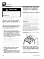
READ THIS FIRST
Modifications
Modifications to this machine may affect compliance with Industry Standards and/or Governmental Regulations.
Any modification must be approved by JLG.
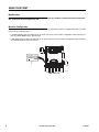
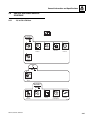
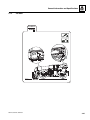
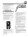
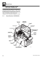
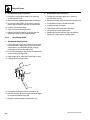
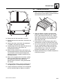
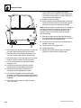
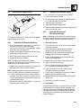
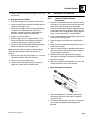
Machine Configuration
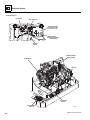
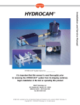
Two configurations of each machine are included in this manual. Determine if machine is equipped with Ultra Low Sulfur
Fuel Decal (1) as indicated below.
• If equipped with the Ultra Low Sulfur decal, all specific references to this machine configuration will be referred to as
Ultra Low Sulfur (ULS) from this point forward.
• If not equipped with the Ultra Low Sulfur decal, all specific references to this machine configuration will be referred to
as Low Sulfur (LS) from this point forward.
ULTRA LOW
SULFUR DIESEL
FUEL ONLY
S < 15 mg/kg
1001125387 A
1
OY2700
REAR VIEW OF CAB
ii
G6-42A, G9-43A, G10-43A
31200792
SECTION CONTENTS
Section
Subject
Section 1
Safety Practices . . . . . . . . . . . . . . . . . . . . . . . . . . . . . . . . . . . . . . . . . . . . . . . . . . . . . . .
1.1
1.2
1.3
1.4
1.5
1.6
1.7
Page
1-1
Introduction . . . . . . . . . . . . . . . . . . . . . . . . . . . . . . . . . . . . . . . . . . . . . . . . . . . . . . . . . .
Disclaimer . . . . . . . . . . . . . . . . . . . . . . . . . . . . . . . . . . . . . . . . . . . . . . . . . . . . . . . . . . .
Operation & Safety Manual . . . . . . . . . . . . . . . . . . . . . . . . . . . . . . . . . . . . . . . . . . . . . .
Do Not Operate Tags . . . . . . . . . . . . . . . . . . . . . . . . . . . . . . . . . . . . . . . . . . . . . . . . . . .
Safety Information . . . . . . . . . . . . . . . . . . . . . . . . . . . . . . . . . . . . . . . . . . . . . . . . . . . . .
Safety Instructions . . . . . . . . . . . . . . . . . . . . . . . . . . . . . . . . . . . . . . . . . . . . . . . . . . . . .
Safety Decals . . . . . . . . . . . . . . . . . . . . . . . . . . . . . . . . . . . . . . . . . . . . . . . . . . . . . . . . .
1-2
1-2
1-2
1-2
1-2
1-3
1-4
Section 2
General Information and Specifications . . . . . . . . . . . . . . . . . . . . . . . . . . . . . . . . . . . .
2-1
2.1
2.2
2.3
2.4
2.5
2.6
2.7
Replacement Parts and Warranty Information . . . . . . . . . . . . . . . . . . . . . . . . . . . . . . . .
Thread Locking Compound . . . . . . . . . . . . . . . . . . . . . . . . . . . . . . . . . . . . . . . . . . . . . .
Torque Charts . . . . . . . . . . . . . . . . . . . . . . . . . . . . . . . . . . . . . . . . . . . . . . . . . . . . . . . .
Specifications . . . . . . . . . . . . . . . . . . . . . . . . . . . . . . . . . . . . . . . . . . . . . . . . . . . . . . . . .
Fluid and Lubricant Capacities. . . . . . . . . . . . . . . . . . . . . . . . . . . . . . . . . . . . . . . . . . . .
Service and Maintenance Schedule . . . . . . . . . . . . . . . . . . . . . . . . . . . . . . . . . . . . . . .
Lubrication Schedule . . . . . . . . . . . . . . . . . . . . . . . . . . . . . . . . . . . . . . . . . . . . . . . . . . .
2-2
2-2
2-3
2-14
2-18
2-21
2-24
...........................................................
3-1
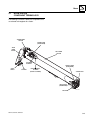
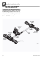
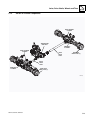
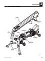
Boom System Component Terminology. . . . . . . . . . . . . . . . . . . . . . . . . . . . . . . . . . . . .
Boom System—Three Section. . . . . . . . . . . . . . . . . . . . . . . . . . . . . . . . . . . . . . . . . . . .
Boom Assembly Maintenance . . . . . . . . . . . . . . . . . . . . . . . . . . . . . . . . . . . . . . . . . . . .
Complete Boom Removal/Installation . . . . . . . . . . . . . . . . . . . . . . . . . . . . . . . . . . . . . .
Boom Section Removal/Installation . . . . . . . . . . . . . . . . . . . . . . . . . . . . . . . . . . . . . . . .
Extend/Retract Chain Removal/Installation . . . . . . . . . . . . . . . . . . . . . . . . . . . . . . . . . .
Push Beam—Extend/Retract Cylinder Removal/Installation . . . . . . . . . . . . . . . . . . . . .
Boom Adjustments . . . . . . . . . . . . . . . . . . . . . . . . . . . . . . . . . . . . . . . . . . . . . . . . . . . . .
Quick Switch Assembly . . . . . . . . . . . . . . . . . . . . . . . . . . . . . . . . . . . . . . . . . . . . . . . . .
Boom Wear Pads . . . . . . . . . . . . . . . . . . . . . . . . . . . . . . . . . . . . . . . . . . . . . . . . . . . . . .
Boom Extend and Retract Chains . . . . . . . . . . . . . . . . . . . . . . . . . . . . . . . . . . . . . . . . .
Forks . . . . . . . . . . . . . . . . . . . . . . . . . . . . . . . . . . . . . . . . . . . . . . . . . . . . . . . . . . . . . . .
Emergency Boom Lowering Procedure . . . . . . . . . . . . . . . . . . . . . . . . . . . . . . . . . . . . .
Troubleshooting . . . . . . . . . . . . . . . . . . . . . . . . . . . . . . . . . . . . . . . . . . . . . . . . . . . . . . .
Push Beam Temporary Brackets . . . . . . . . . . . . . . . . . . . . . . . . . . . . . . . . . . . . . . . . . .
3-3
3-4
3-4
3-5
3-6
3-15
3-16
3-20
3-25
3-26
3-28
3-31
3-31
3-34
3-37
Section 4
Cab and Covers . . . . . . . . . . . . . . . . . . . . . . . . . . . . . . . . . . . . . . . . . . . . . . . . . . . . . . . .
4-1
Section 3
Boom
3.1
3.2
3.3
3.4
3.5
3.6
3.7
3.8
3.9
3.10
3.11
3.12
3.13
3.14
3.15
4.1
4.2
4.3
4.4
4.5
Operator Cab and Covers Component Terminology . . . . . . . . . . . . . . . . . . . . . . . . . . .
Operator Cab . . . . . . . . . . . . . . . . . . . . . . . . . . . . . . . . . . . . . . . . . . . . . . . . . . . . . . . . .
Cab Components . . . . . . . . . . . . . . . . . . . . . . . . . . . . . . . . . . . . . . . . . . . . . . . . . . . . . .
Cab Removal . . . . . . . . . . . . . . . . . . . . . . . . . . . . . . . . . . . . . . . . . . . . . . . . . . . . . . . . .
Cab Installation . . . . . . . . . . . . . . . . . . . . . . . . . . . . . . . . . . . . . . . . . . . . . . . . . . . . . . .
G6-42A, G9-43A, G10-43A
4-2
4-4
4-4
4-10
4-11
i
Section
Subject
Page
Section 5
Axles, Drive Shafts, Wheels and Tires . . . . . . . . . . . . . . . . . . . . . . . . . . . . . . . . . . . . . .
5.1
5.2
5.3
5.4
5.5
5.6
5.7
5.8
5-1
Axle, Drive Shaft and Wheel Component Terminology . . . . . . . . . . . . . . . . . . . . . . . . .
Axle Serial Number . . . . . . . . . . . . . . . . . . . . . . . . . . . . . . . . . . . . . . . . . . . . . . . . . . . .
Axle Specifications And Maintenance Information . . . . . . . . . . . . . . . . . . . . . . . . . . . . .
Axle Replacement . . . . . . . . . . . . . . . . . . . . . . . . . . . . . . . . . . . . . . . . . . . . . . . . . . . . .
Drive Shafts . . . . . . . . . . . . . . . . . . . . . . . . . . . . . . . . . . . . . . . . . . . . . . . . . . . . . . . . . .
Wheels and Tires . . . . . . . . . . . . . . . . . . . . . . . . . . . . . . . . . . . . . . . . . . . . . . . . . . . . . .
Brakes . . . . . . . . . . . . . . . . . . . . . . . . . . . . . . . . . . . . . . . . . . . . . . . . . . . . . . . . . . . . . .
Towing a Disabled Machine . . . . . . . . . . . . . . . . . . . . . . . . . . . . . . . . . . . . . . . . . . . . . .
5-2
5-4
5-4
5-4
5-9
5-10
5-11
5-12
Section 6
Transmission . . . . . . . . . . . . . . . . . . . . . . . . . . . . . . . . . . . . . . . . . . . . . . . . . . . . . . . . . .
6-1
6.1
6.2
6.3
6.4
6.5
6.6
6.7
Transmission Assembly Component Terminology . . . . . . . . . . . . . . . . . . . . . . . . . . . . .
Transmission Serial Number . . . . . . . . . . . . . . . . . . . . . . . . . . . . . . . . . . . . . . . . . . . . .
Transmission Specifications And Maintenance Information. . . . . . . . . . . . . . . . . . . . . .
Transmission Replacement . . . . . . . . . . . . . . . . . . . . . . . . . . . . . . . . . . . . . . . . . . . . . .
Transmission Cooler Thermal By-Pass Valve . . . . . . . . . . . . . . . . . . . . . . . . . . . . . . . .
Torque Convertor Diaphragm. . . . . . . . . . . . . . . . . . . . . . . . . . . . . . . . . . . . . . . . . . . . .
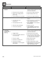
Troubleshooting . . . . . . . . . . . . . . . . . . . . . . . . . . . . . . . . . . . . . . . . . . . . . . . . . . . . . . .
6-2
6-3
6-3
6-3
6-7
6-8
6-9
...........................................................
7-1
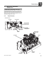
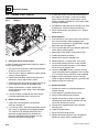
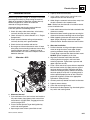
Introduction—Cummins . . . . . . . . . . . . . . . . . . . . . . . . . . . . . . . . . . . . . . . . . . . . . . . . .
Engine Cooling System . . . . . . . . . . . . . . . . . . . . . . . . . . . . . . . . . . . . . . . . . . . . . . . . .
Engine Electrical System . . . . . . . . . . . . . . . . . . . . . . . . . . . . . . . . . . . . . . . . . . . . . . . .
Fuel System . . . . . . . . . . . . . . . . . . . . . . . . . . . . . . . . . . . . . . . . . . . . . . . . . . . . . . . . . .
Engine Exhaust System . . . . . . . . . . . . . . . . . . . . . . . . . . . . . . . . . . . . . . . . . . . . . . . . .
Air Cleaner Assembly. . . . . . . . . . . . . . . . . . . . . . . . . . . . . . . . . . . . . . . . . . . . . . . . . . .
Engine Replacement . . . . . . . . . . . . . . . . . . . . . . . . . . . . . . . . . . . . . . . . . . . . . . . . . . .
7-2
7-5
7-8
7-8
7-11
7-13
7-15
Section 8
Hydraulic System . . . . . . . . . . . . . . . . . . . . . . . . . . . . . . . . . . . . . . . . . . . . . . . . . . . . . . .
8-1
Section 7
Engine
7.1
7.2
7.3
7.4
7.5
7.6
7.7
8.1
8.2
8.3
8.4
8.5
8.6
8.7
8.8
ii
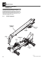
Hydraulic Component Terminology . . . . . . . . . . . . . . . . . . . . . . . . . . . . . . . . . . . . . . . .
Safety Information . . . . . . . . . . . . . . . . . . . . . . . . . . . . . . . . . . . . . . . . . . . . . . . . . . . . .
Hydraulic Pressure Diagnosis . . . . . . . . . . . . . . . . . . . . . . . . . . . . . . . . . . . . . . . . . . . .
Hydraulic Circuits . . . . . . . . . . . . . . . . . . . . . . . . . . . . . . . . . . . . . . . . . . . . . . . . . . . . . .
Hydraulic Reservoir . . . . . . . . . . . . . . . . . . . . . . . . . . . . . . . . . . . . . . . . . . . . . . . . . . . .
Implement Pump . . . . . . . . . . . . . . . . . . . . . . . . . . . . . . . . . . . . . . . . . . . . . . . . . . . . . .
Control Valves . . . . . . . . . . . . . . . . . . . . . . . . . . . . . . . . . . . . . . . . . . . . . . . . . . . . . . . .
Hydraulic Cylinders . . . . . . . . . . . . . . . . . . . . . . . . . . . . . . . . . . . . . . . . . . . . . . . . . . . .
8-2
8-4
8-5
8-6
8-15
8-16
8-17
8-23
G6-42A, G9-43A, G10-43A
Section
Subject
Section 9
Electrical System . . . . . . . . . . . . . . . . . . . . . . . . . . . . . . . . . . . . . . . . . . . . . . . . . . . . . .
9.1
9.2
9.3
9.4
9.5
9.6
9.7
9.8
9.9
9.10
9.11
9.12
9.13
Electrical Component Terminology . . . . . . . . . . . . . . . . . . . . . . . . . . . . . . . . . . . . . . . .
Specifications . . . . . . . . . . . . . . . . . . . . . . . . . . . . . . . . . . . . . . . . . . . . . . . . . . . . . . . . .
Safety Information . . . . . . . . . . . . . . . . . . . . . . . . . . . . . . . . . . . . . . . . . . . . . . . . . . . . .
Fuses and Relays . . . . . . . . . . . . . . . . . . . . . . . . . . . . . . . . . . . . . . . . . . . . . . . . . . . . .
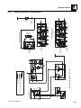
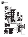
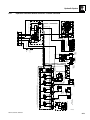
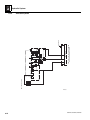
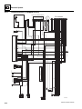
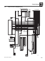
Electrical System Schematics . . . . . . . . . . . . . . . . . . . . . . . . . . . . . . . . . . . . . . . . . . . .
Engine Start Circuit . . . . . . . . . . . . . . . . . . . . . . . . . . . . . . . . . . . . . . . . . . . . . . . . . . . .
Charging Circuit . . . . . . . . . . . . . . . . . . . . . . . . . . . . . . . . . . . . . . . . . . . . . . . . . . . . . . .
Window Wiper/Washer Windshield Wiper Motor . . . . . . . . . . . . . . . . . . . . . . . . . . . . . .
Cab Heater and Fan . . . . . . . . . . . . . . . . . . . . . . . . . . . . . . . . . . . . . . . . . . . . . . . . . . .
Solenoids, Sensors and Senders. . . . . . . . . . . . . . . . . . . . . . . . . . . . . . . . . . . . . . . . . .
Display Gauge and Dash Switches . . . . . . . . . . . . . . . . . . . . . . . . . . . . . . . . . . . . . . . .
Hand Held Analyzer - G9-43A and G10-43A . . . . . . . . . . . . . . . . . . . . . . . . . . . . . . . . .
SAE Diagnostic Trouble and Fault Codes . . . . . . . . . . . . . . . . . . . . . . . . . . . . . . . . . . .
G6-42A, G9-43A, G10-43A
Page
9-1
9-3
9-5
9-5
9-5
9-8
9-14
9-15
9-17
9-19
9-20
9-24
9-27
9-38
iii
Section
iv
Subject
Page
G6-42A, G9-43A, G10-43A
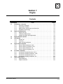
Section 1
Safety Practices
Contents
PARAGRAPH
1.1
1.2
1.3
1.4
1.5
1.6
1.7
TITLE
Introduction . . . . . . . . . . . . . . . . . . . . . . . . . . . . . . . . . . . . . . . . . . . . . . . . . . . . . . .
Disclaimer . . . . . . . . . . . . . . . . . . . . . . . . . . . . . . . . . . . . . . . . . . . . . . . . . . . . . . . .
Operation & Safety Manual. . . . . . . . . . . . . . . . . . . . . . . . . . . . . . . . . . . . . . . . . . .
Do Not Operate Tags. . . . . . . . . . . . . . . . . . . . . . . . . . . . . . . . . . . . . . . . . . . . . . . .
Safety Information. . . . . . . . . . . . . . . . . . . . . . . . . . . . . . . . . . . . . . . . . . . . . . . . . .
1.5.1
Safety Alert System and Signal Words . . . . . . . . . . . . . . . . . . . . . . . . . . .
Safety Instructions . . . . . . . . . . . . . . . . . . . . . . . . . . . . . . . . . . . . . . . . . . . . . . . . .
1.6.1
Personal Hazards . . . . . . . . . . . . . . . . . . . . . . . . . . . . . . . . . . . . . . . . . . .
1.6.2
Equipment Hazards. . . . . . . . . . . . . . . . . . . . . . . . . . . . . . . . . . . . . . . . . .
1.6.3
General Hazards . . . . . . . . . . . . . . . . . . . . . . . . . . . . . . . . . . . . . . . . . . . .
1.6.4
Operational Hazards . . . . . . . . . . . . . . . . . . . . . . . . . . . . . . . . . . . . . . . . .
Safety Decals . . . . . . . . . . . . . . . . . . . . . . . . . . . . . . . . . . . . . . . . . . . . . . . . . . . . . .
G6-42A, G9-43A, G10-43A
PAGE
1-2
1-2
1-2
1-2
1-2
1-2
1-3
1-3
1-3
1-3
1-4
1-4
1-1
Safety Practices
1.1
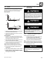
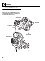
INTRODUCTION
1.4
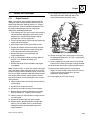
DO NOT OPERATE TAGS
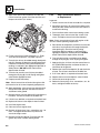
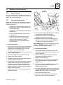
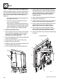
This service manual provides general directions for
accomplishing service and repair procedures. Following
the procedures in this manual will help assure safety and
equipment reliability.
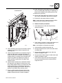
Place Do Not Operate Tags on the ignition key switch and
the steering wheel before attempting to perform any
service or maintenance. Remove key and disconnect
battery leads.
Read, understand and follow the information in this
manual, and obey all locally approved safety practices,
procedures, rules, codes, regulations and laws.
1.5
These instructions cannot cover all details or variations in
the equipment, procedures, or processes described, nor
provide directions for meeting every possible contingency
during operation, maintenance, or testing. When additional
information is desired consult the local JLG Distributor.
Many factors contribute to unsafe conditions: carelessness,
fatigue, overload, inattentiveness, unfamiliarity, even
drugs and alcohol, among others. For optimal safety,
encourage everyone to think, and to act, safely.
SAFETY INFORMATION
To avoid possible death or injury, carefully read,
understand and comply with all safety messages.
In the event of an accident, know where to obtain medical
assistance and how to use a first-aid kit and fire
extinguisher/fire suppression system. Keep emergency
telephone numbers (fire department, ambulance, rescue
squad/paramedics, police department, etc.) nearby. If
working alone, check with another person routinely to
help assure personal safety.
Appropriate service methods and proper repair
procedures are essential for the safety of the individual
doing the work, for the safety of the operator, and for the
safe, reliable operation of the machine. All references to
the right side, left side, front and rear are given from the
operator’s seat looking in a forward direction.
1.5.1
Supplementary information is available from JLG in the
form of Service Bulletins, Service Campaigns, Service
Training Schools, the JLG website, other literature and
through updates to the manual itself.
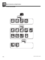
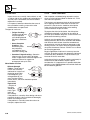
DANGER indicates an imminently hazardous situation
which, if not avoided, will result in death or serious injury.
1.2
DANGER
WARNING
DISCLAIMER
All information in this manual is based on the latest
product information available at the time of publication.
JLG reserves the right to make changes and
improvements to its products, and to discontinue the
manufacture of any product, at its discretion at any time
without public notice or obligation.
1.3
Safety Alert System and Signal Words
WARNING indicates a potentially hazardous situation
which, if not avoided, could result in death or serious
injury.
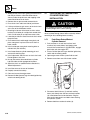
CAUTION
OPERATION & SAFETY MANUAL
The mechanic must not operate the machine until the
Operation & Safety Manual has been read and
understood, training has been accomplished and
operation of the machine has been completed under the
supervision of an experienced and qualified operator.
CAUTION indicates a potentially hazardous situation
which, if not avoided, may result in minor or moderate
injury.
An Operation & Safety Manual is supplied with each
machine and must be kept in the manual holder located
in the cab. In the event that the Operation & Safety
Manual is missing, consult the local JLG Distributor
before proceeding.
1-2
G6-42A, G9-43A, G10-43A
Safety Practices
1.6
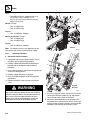
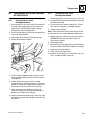
SAFETY INSTRUCTIONS
Following are general safety statements to consider
BEFORE performing maintenance procedures on the
telehandler. Additional statements related to specific
tasks and procedures are located throughout this manual
and are listed prior to any work instructions to provide
safety information before the potential of a hazard occurs.
For all safety messages, carefully read, understand and
follow the instructions BEFORE proceeding.
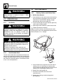
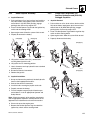
1.6.1
Personal Hazards
PERSONAL SAFETY GEAR: Wear all the protective
clothing and personal safety gear necessary to perform
the job safely. This might include heavy gloves, safety
glasses or goggles, filter mask or respirator, safety shoes
or a hard hat.
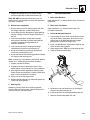
LIFTING: NEVER lift a heavy object without the help of at
least one assistant or a suitable sling and hoist.
1.6.2
Equipment Hazards
LIFTING OF EQUIPMENT: Before using any lifting
equipment (chains, slings, brackets, hooks, etc.), verify
that it is of the proper capacity, in good working order, and
is properly attached.
NEVER stand or otherwise become positioned under a
suspended load or under raised equipment. The load or
equipment could fall or tip.
DO NOT use a hoist, jack or jack stands only to support
equipment. Always support equipment with the proper
capacity blocks or stands properly rated for the load.
1.6.3
General Hazards
SOLVENTS: Only use approved solvents that are known
to be safe for use.
HOUSEKEEPING: Keep the work area and operator’s
cab clean, and remove all hazards (debris, oil, tools, etc.).
FIRST AID: Immediately clean, dress and report all injuries
(cuts, abrasions, burns, etc.), no matter how minor the
injury may seem. Know the location of a First Aid Kit, and
know how to use it.
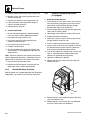
CLEANLINESS: Wear eye protection and clean all
components with a high-pressure or steam cleaner
before attempting service.
When removing hydraulic components, plug hose ends
and connections to prevent excess leakage and
contamination. Place a suitable catch basin beneath the
machine to capture fluid run-off.
It is good practice to avoid pressure-washing electrical/
electronic components. In the event pressure-washing
the machine is needed, ensure machine is shut down
before pressure-washing. Should pressure-washing be
utilized to wash areas containing electrical/electronic
components, it is recommended a maximum pressure of
750 psi (52 bar) at a minimum distance of 12 in (30,5 cm)
away from these components. If electrical/electronic
components are sprayed, spraying must not be direct
and for brief time periods to avoid heavy saturation,
Check and obey all Federal, State and/or Local
regulations regarding waste storage, disposal
and recycling.
HAND TOOLS: Always use the proper tool for the job;
keep tools clean and in good working order, and use
special service tools only as recommended.
G6-42A, G9-43A, G10-43A
1-3
Safety Practices
1.6.4
Operational Hazards
ENGINE: Stop the engine before performing any service
unless specifically instructed otherwise.
VENTILATION: Avoid prolonged engine operation in
enclosed areas without adequate ventilation.
SOFT SURFACES AND SLOPES: NEVER work on a
machine that is parked on a soft surface or slope. The
machine must be on a hard level surface, with the wheels
blocked before performing any service.
FLUID PRESSURE: Before loosening any hydraulic or
diesel fuel component, hose or tube, turn the engine
OFF. Wear heavy, protective gloves and eye protection.
NEVER check for leaks using any part of your body; use
a piece of cardboard or wood instead. If injured, seek
medical attention immediately. Diesel fluid leaking under
pressure can explode. Hydraulic fluid and diesel fuel
leaking under pressure can penetrate the skin, cause
infection, gangrene and other serious personal injury.
Engine fuel lines are pressurized. DO NOT attempt
repairs unless specific training has been completed.
Refer to the engine manufacturers’ manual for specific
details concerning the fuel system.
Relieve all pressure before disconnecting any
component, part, line or hose. Slowly loosen parts and
allow release of residual pressure before removing any
part or component. Before starting the engine or applying
pressure, use components, parts, hoses and pipes that
are in good condition, connected properly and are
tightened to the proper torque. Capture fluid in an
appropriate container and dispose of in accordance with
prevailing environmental regulations.
DO NOT mix gasoline or alcohol with diesel fuel. The
mixture can cause an explosion.
PRESSURE TESTING: When conducting any test, only
use test equipment that is correctly calibrated and in good
condition. Use the correct equipment in the proper
manner, and make changes or repairs as indicated by the
test procedure to achieve the desired result.
LEAVING MACHINE: Lower the forks or attachment to
the ground before leaving the machine.
TIRES: Always keep tires inflated to the proper pressure
to help prevent tipover. DO NOT over-inflate tires.
NEVER use mismatched tire types, sizes or ply ratings.
Always use matched sets according to machine
specifications.
MAJOR COMPONENTS: Never alter, remove, or
substitute any items such as counterweights, tires,
batteries or other items that may reduce or affect the
overall weight or stability of the machine.
BATTERY: DO NOT charge a frozen battery.Charging
a frozen battery may cause it to explode. Allow the
battery to thaw before jump-starting or connecting a
battery charger.
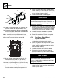
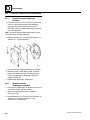
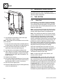
1.7
SAFETY DECALS
Check that all safety decals are present and readable on
the machine. Refer to the Operation & Safety Manual
supplied with machine for information.
COOLANT SYSTEM CAP: The cooling system is under
pressure, and escaping coolant can cause severe burns
and eye injury. To prevent personal injury, NEVER
remove the coolant system cap while the cooling system
is hot. Wear safety glasses. Turn the coolant system cap
to allow pressure to escape before removing the cap
completely. Failure to follow the safety practices could
result in death or serious injury.
FLUID FLAMABILTITY: DO NOT service the fuel or
hydraulic systems near an open flame, sparks or smoking
materials.
Properly disconnect battery(s) prior to servicing the fuel
or hydraulic systems.
NEVER drain or store fluids in an open container. Engine
fuel and hydraulic fluid are flammable and can cause a
fire and/or explosion.
1-4
G6-42A, G9-43A, G10-43A
Section 2
General Information and Specifications
Contents
PARAGRAPH
2.1
2.2
2.3
2.4
2.5
2.6
2.7
TITLE
Replacement Parts and Warranty Information . . . . . . . . . . . . . . . . . . . . . . . . . . .
Thread Locking Compound . . . . . . . . . . . . . . . . . . . . . . . . . . . . . . . . . . . . . . . . . .
Torque Charts . . . . . . . . . . . . . . . . . . . . . . . . . . . . . . . . . . . . . . . . . . . . . . . . . . . . .
2.3.1
SAE Fastener Torque Chart . . . . . . . . . . . . . . . . . . . . . . . . . . . . . . . . . . .
2.3.2
Metric Fastener Torque Chart . . . . . . . . . . . . . . . . . . . . . . . . . . . . . . . . . .
2.3.3
Hydraulic Hose Torque Chart . . . . . . . . . . . . . . . . . . . . . . . . . . . . . . . . . .
Specifications . . . . . . . . . . . . . . . . . . . . . . . . . . . . . . . . . . . . . . . . . . . . . . . . . . . . .
2.4.1
Travel Speeds . . . . . . . . . . . . . . . . . . . . . . . . . . . . . . . . . . . . . . . . . . . . . .
2.4.2
Hydraulic Cylinder Performance . . . . . . . . . . . . . . . . . . . . . . . . . . . . . . . .
2.4.3
Electrical SystemEngine System . . . . . . . . . . . . . . . . . . . . . . . . . . . . . . .
2.4.4
Engine Specifications . . . . . . . . . . . . . . . . . . . . . . . . . . . . . . . . . . . . . . . .
2.4.5
Tires . . . . . . . . . . . . . . . . . . . . . . . . . . . . . . . . . . . . . . . . . . . . . . . . . . . . .
Fluid and Lubricant Capacities . . . . . . . . . . . . . . . . . . . . . . . . . . . . . . . . . . . . . . .
2.5.1
Fluids (if Equipped for ULS) . . . . . . . . . . . . . . . . . . . . . . . . . . . . . . . . . . .
2.5.2
Fluids (if Equipped for LS). . . . . . . . . . . . . . . . . . . . . . . . . . . . . . . . . . . . .
2.5.3
Capacities . . . . . . . . . . . . . . . . . . . . . . . . . . . . . . . . . . . . . . . . . . . . . . . . .
Service and Maintenance Schedule . . . . . . . . . . . . . . . . . . . . . . . . . . . . . . . . . . .
2.6.1
10, 1st 50 & 50 Hour . . . . . . . . . . . . . . . . . . . . . . . . . . . . . . . . . . . . . . . . .
2.6.2
1st 250, 250 & 500 Hour . . . . . . . . . . . . . . . . . . . . . . . . . . . . . . . . . . . . . .
2.6.3
1000, 1500 & 2000 Hour . . . . . . . . . . . . . . . . . . . . . . . . . . . . . . . . . . . . . .
Lubrication Schedule . . . . . . . . . . . . . . . . . . . . . . . . . . . . . . . . . . . . . . . . . . . . . . .
2.7.1
50 Hour . . . . . . . . . . . . . . . . . . . . . . . . . . . . . . . . . . . . . . . . . . . . . . . . . . .
2.7.2
250 Hour . . . . . . . . . . . . . . . . . . . . . . . . . . . . . . . . . . . . . . . . . . . . . . . . . .
2.7.3
1000 Hour . . . . . . . . . . . . . . . . . . . . . . . . . . . . . . . . . . . . . . . . . . . . . . . . .
G6-42A, G9-43A, G10-43A
PAGE
2-2
2-2
2-3
2-3
2-9
2-13
2-14
2-14
2-14
2-16
2-16
2-17
2-18
2-18
2-19
2-20
2-21
2-21
2-22
2-23
2-24
2-24
2-25
2-26
2-1
General Information and Specifications
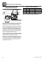
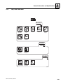
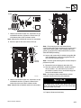
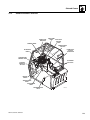
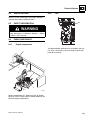
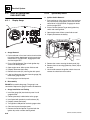
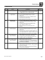
REPLACEMENT PARTS AND
WARRANTY INFORMATION
2.2
-10
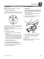
THREAD LOCKING COMPOUND
JLG P/N Loctite® ND Industries
50 60 80
70
2.1
40
20 30
10
Description
0100011
242TM
Vibra-TITETM121
Medium Strength (Blue)
1001095650
243TM
Vibra-TITETM122
Medium Strength (Blue)
0100019
271TM
Vibra-TITETM140
High Strength (Red)
0100071
262TM
Vibra-TITETM131
Medium - High Strength (Red)
Loctite® 243TM can be substituted in place of Loctite® 242TM. VibraTITETM 122 can be substituted in place of Vibra-TITETM 121.
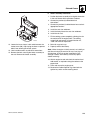
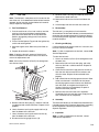
1
MY8100
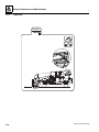
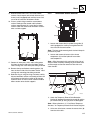
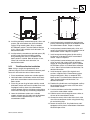
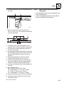
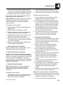
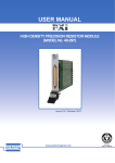
Before ordering parts or initiating service inquiries, make
note of the machine serial number. The machine serial
number plate (1) is located as indicated in the figure.
Note: The replacement of any part on this machine with
any other than JLG authorized replacement parts can
adversely affect the performance, durability, or safety of
the machine, and will void the warranty. JLG disclaims
liability for any claims or damages, whether regarding
property damage, personal injury or death arising out of
the use of unauthorized replacement parts.
A warranty registration form must be filled out by the JLG
Distributor, signed by the purchaser and returned to JLG
when the machine is sold and/or put into use.
Registration activates the warranty period and helps to
assure that warranty claims are promptly processed. To
guarantee full warranty service, verify that the distributor
has returned the business reply card of the warranty
registration form to JLG.
2-2
G6-42A, G9-43A, G10-43A
General Information and Specifications
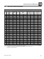
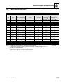
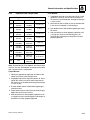
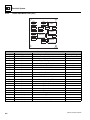
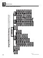
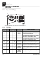
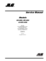
2.3
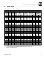
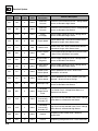
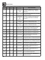
TORQUE CHARTS
2.3.1
SAE Fastener Torque Chart
Values for Zinc Yellow Chromate Fasteners (Ref 4150707)
SAE GRADE 5 BOLTS & GRADE 2 NUTS
Tensile
Stress Area
Clamp
Load
Torque
(Dry)
Torque
Lubricated
Size
TPI
Bolt Dia
In
Sq In
LB
IN-LB
[N.m]
IN-LB
[N.m]
4
40
0.1120
0.00604
380
8
0.9
6
0.7
48
0.1120
0.00661
420
9
1.0
7
0.8
32
0.1380
0.00909
580
16
1.8
12
1.4
40
0.1380
0.01015
610
18
2.0
13
1.5
6
8
10
1/4
5/16
3/8
7/16
1/2
9/16
5/8
3/4
7/8
1
1 1/8
1 1/4
1 3/8
1 1/2
32
0.1640
0.01400
900
30
3.4
22
2.5
36
0.1640
0.01474
940
31
3.5
23
2.6
3.5
Torque
(Loctite® 242TM or 271TM
or Vibra-TITETM
111 or 140)
IN-LB
[N.m]
Torque
(Loctite® 262TM or
Vibra-TITETM 131)
IN-LB
[N.m]
[N.m]
24
0.1900
0.01750
1120
43
4.8
32
32
0.1900
0.02000
1285
49
5.5
36
4
20
0.2500
0.0318
2020
96
10.8
75
9
105
12
28
0.2500
0.0364
2320
120
13.5
86
10
135
15
In
Sq In
LB
FT-LB
[N.m]
FT-LB
[N.m]
FT-LB
[N.m]
FT-LB
18
0.3125
0.0524
3340
17
23
13
18
19
26
16
22
24
0.3125
0.0580
3700
19
26
14
19
21
29
17
23
16
0.3750
0.0775
4940
30
41
23
31
35
48
28
38
24
0.3750
0.0878
5600
35
47
25
34
40
54
32
43
14
0.4375
0.1063
6800
50
68
35
47
55
75
45
61
20
0.4375
0.1187
7550
55
75
40
54
60
82
50
68
13
0.5000
0.1419
9050
75
102
55
75
85
116
68
92
20
0.5000
0.1599
10700
90
122
65
88
100
136
80
108
12
0.5625
0.1820
11600
110
149
80
108
120
163
98
133
18
0.5625
0.2030
12950
120
163
90
122
135
184
109
148
11
0.6250
0.2260
14400
150
203
110
149
165
224
135
183
18
0.6250
0.2560
16300
170
230
130
176
190
258
153
207
10
0.7500
0.3340
21300
260
353
200
271
285
388
240
325
16
0.7500
0.3730
23800
300
407
220
298
330
449
268
363
9
0.8750
0.4620
29400
430
583
320
434
475
646
386
523
14
0.8750
0.5090
32400
470
637
350
475
520
707
425
576
785
8
1.0000
0.6060
38600
640
868
480
651
675
918
579
12
1.0000
0.6630
42200
700
949
530
719
735
1000
633
858
7
1.1250
0.7630
42300
800
1085
600
813
840
1142
714
968
12
1.1250
0.8560
47500
880
1193
660
895
925
1258
802
1087
7
1.2500
0.9690
53800
1120
1518
840
1139
1175
1598
1009
1368
12
1.2500
1.0730
59600
1240
1681
920
1247
1300
1768
1118
1516
6
1.3750
1.1550
64100
1460
1979
1100
1491
1525
2074
1322
1792
12
1.3750
1.3150
73000
1680
2278
1260
1708
1750
2380
1506
2042
6
1.5000
1.4050
78000
1940
2630
1460
1979
2025
2754
1755
2379
12
1.5000
1.5800
87700
2200
2983
1640
2224
2300
3128
1974
2676
NOTES: 1. THESE TORQUE VALUES DO NOT APPLY TO CADMIUM PLATED FASTENERS
5000059K
2. ALL TORQUE VALUES ARE STATIC TORQUE MEASURED PER STANDARD AUDIT METHODS TOLERANCE = ±10%
3. * ASSEMBLY USES HARDENED WASHER
G6-42A, G9-43A, G10-43A
2-3
General Information and Specifications
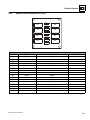
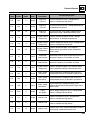
2.3.1
SAE Fastener Torque Chart (Continued)
Values for Zinc Yellow Chromate Fasteners (Ref 4150707)
SAE GRADE 8 (HEX HD) BOLTS & GRADE 8 NUTS*
Tensile Stress
Clamp Load
Area
Size
TPI
Bolt Dia
In
Sq In
4
40
0.1120
0.00604
48
0.1120
0.00661
32
0.1380
0.00909
40
0.1380
0.01015
6
8
LB
Torque
(Dry or Loctite® 263)
K=0.20
IN-LB
[N.m]
Torque
(Loctite® 242TM or 271TM or
Vibra-TITETM 111 or 140)
K=0.18
IN-LB
[N.m]
Torque
(Loctite® 262TM or
Vibra-TITETM 131)
K=0.15
IN-LB
[N.m]
32
0.1640
0.01400
36
0.1640
0.01474
1320
43
5
10
24
0.1900
0.01750
1580
60
7
32
0.1900
0.02000
1800
68
8
1/4
20
0.2500
0.0318
2860
143
16
129
28
0.2500
0.0364
3280
164
19
148
17
In
Sq In
LB
FT-LB
[N.m]
FT-LB
[N.m]
FT-LB
18
0.3125
0.0524
4720
25
35
20
25
20
25
24
0.3125
0.0580
5220
25
35
25
35
20
25
16
0.3750
0.0775
7000
45
60
40
55
35
50
24
0.3750
0.0878
7900
50
70
45
60
35
50
5/16
3/8
7/16
1/2
9/16
5/8
3/4
7/8
1
1 1/8
1 1/4
1 3/8
1 1/2
15
[N.m]
14
0.4375
0.1063
9550
70
95
65
90
50
70
20
0.4375
0.1187
10700
80
110
70
95
60
80
13
0.5000
0.1419
12750
105
145
95
130
80
110
20
0.5000
0.1599
14400
120
165
110
150
90
120
12
0.5625
0.1820
16400
155
210
140
190
115
155
18
0.5625
0.2030
18250
170
230
155
210
130
175
11
0.6250
0.2260
20350
210
285
190
260
160
220
18
0.6250
0.2560
23000
240
325
215
290
180
245
10
0.7500
0.3340
30100
375
510
340
460
280
380
16
0.7500
0.3730
33600
420
570
380
515
315
430
9
0.8750
0.4620
41600
605
825
545
740
455
620
14
0.8750
0.5090
45800
670
910
600
815
500
680
8
1.0000
0.6060
51500
860
1170
770
1045
645
875
12
1.0000
0.6630
59700
995
1355
895
1215
745
1015
7
1.1250
0.7630
68700
1290
1755
1160
1580
965
1310
12
1.1250
0.8560
77000
1445
1965
1300
1770
1085
1475
7
1.2500
0.9690
87200
1815
2470
1635
2225
1365
1855
12
1.2500
1.0730
96600
2015
2740
1810
2460
1510
2055
6
1.3750
1.1550
104000
2385
3245
2145
2915
1785
2430
12
1.3750
1.3150
118100
2705
3680
2435
3310
2030
2760
6
1.5000
1.4050
126500
3165
4305
2845
3870
2370
3225
12
1.5000
1.5800
142200
3555
4835
3200
4350
2665
3625
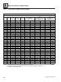
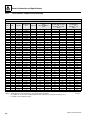
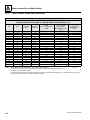
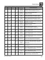
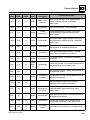
NOTES: 1. THESE TORQUE VALUES DO NOT APPLY TO CADMIUM PLATED FASTENERS
5000059K
2. ALL TORQUE VALUES ARE STATIC TORQUE MEASURED PER STANDARD AUDIT METHODS TOLERANCE = ±10%
3. * ASSEMBLY USES HARDENED WASHER
2-4
G6-42A, G9-43A, G10-43A
General Information and Specifications
2.3.1
SAE Fastener Torque Chart (Continued)
Values for Magni Coating Fasteners (Ref 4150701)
SAE GRADE 5 BOLTS & GRADE 2 NUTS
Torque
(Dry)
K=0.17
Tensile Stress
Clamp Load
Area
Torque
(Loctite® 242TM or 271TM or
Vibra-TITETM 111 or 140)
K=0.16
IN-LB
[N.m]
Torque
(Loctite® 262TM or
Vibra-TITETM 131)
K=0.15
IN-LB
[N.m]
Size
TPI
Bolt Dia
In
Sq In
LB
IN-LB
4
40
0.1120
0.00604
380
7
0.8
48
0.1120
0.00661
420
8
0.9
32
0.1380
0.00909
580
14
1.5
40
0.1380
0.01015
610
14
1.6
8
32
0.1640
0.01400
900
25
2.8
36
0.1640
0.01474
940
26
2.9
10
24
0.1900
0.01750
1120
36
4.1
32
0.1900
0.02000
1285
42
4.7
1/4
20
0.2500
0.0318
2020
86
9.7
80
9
28
0.2500
0.0364
2320
99
11.1
95
11
In
Sq In
LB
FT-LB
[N.m]
FT-LB
[N.m]
FT-LB
18
0.3125
0.0524
3340
15
20
14
19
15
20
24
0.3125
0.0580
3700
15
20
15
21
15
20
6
5/16
3/8
7/16
1/2
9/16
[N.m]
[N.m]
16
0.3750
0.0775
4940
25
35
25
34
25
34
24
0.3750
0.0878
5600
30
40
28
38
25
34
14
0.4375
0.1063
6800
40
55
40
54
35
48
20
0.4375
0.1187
7550
45
60
44
60
40
54
75
13
0.5000
0.1419
9050
65
90
60
82
55
20
0.5000
0.1599
10700
75
100
71
97
65
88
12
0.5625
0.1820
11600
90
120
87
118
80
109
18
0.5625
0.2030
12950
105
145
97
132
90
122
5/8
11
0.6250
0.2260
14400
130
175
120
163
115
156
18
0.6250
0.2560
16300
145
195
136
185
125
170
3/4
10
0.7500
0.3340
21300
225
305
213
290
200
272
7/8
1
1 1/8
1 1/4
1 3/8
1 1/2
16
0.7500
0.3730
23800
255
345
238
324
225
306
9
0.8750
0.4620
29400
365
495
343
466
320
435
14
0.8750
0.5090
32400
400
545
378
514
355
483
8
1.0000
0.6060
38600
545
740
515
700
480
653
12
1.0000
0.6630
42200
600
815
563
765
530
721
7
1.1250
0.7630
42300
675
920
635
863
595
809
12
1.1250
0.8560
47500
755
1025
713
969
670
911
7
1.2500
0.9690
53800
955
1300
897
1219
840
1142
12
1.2500
1.0730
59600
1055
1435
993
1351
930
1265
6
1.3750
1.1550
64100
1250
1700
1175
1598
1100
1496
12
1.3750
1.3150
73000
1420
1930
1338
1820
1255
1707
6
1.5000
1.4050
78000
1660
2260
1560
2122
1465
1992
12
1.5000
1.5800
87700
1865
2535
1754
2385
1645
2237
NOTES: 1. THESE TORQUE VALUES DO NOT APPLY TO CADMIUM PLATED FASTENERS
5000059K
2. ALL TORQUE VALUES ARE STATIC TORQUE MEASURED PER STANDARD AUDIT METHODS TOLERANCE = ±10%
3. * ASSEMBLY USES HARDENED WASHER
G6-42A, G9-43A, G10-43A
2-5
General Information and Specifications
2.3.1
SAE Fastener Torque Chart (Continued)
Values for Magni Coating Fasteners (Ref 4150701)
SAE GRADE 8 (HEX HD) BOLTS & GRADE 8 NUTS*
Tensile Stress
Clamp Load
Area
Size
TPI
Bolt Dia
In
Sq In
4
40
0.1120
0.00604
48
0.1120
0.00661
32
0.1380
0.00909
40
0.1380
0.01015
6
8
LB
Torque
(Dry or Loctite® 263)
K=0.17
IN-LB
[N.m]
Torque
(Loctite® 242TM or 271TM or
Vibra-TITETM 111 or 140)
K=0.16
IN-LB
[N.m]
Torque
(Loctite® 262TM or
Vibra-TITETM 131)
K=0.15
IN-LB
[N.m]
32
0.1640
0.01400
36
0.1640
0.01474
1320
37
4
10
24
0.1900
0.01750
1580
51
6
32
0.1900
0.02000
1800
58
7
1/4
20
0.2500
0.0318
2860
122
14
114
28
0.2500
0.0364
3280
139
16
131
15
In
Sq In
LB
FT-LB
[N.m]
FT-LB
[N.m]
FT-LB
18
0.3125
0.0524
4720
20
25
20
25
20
25
24
0.3125
0.0580
5220
25
35
20
25
20
25
16
0.3750
0.0775
7000
35
50
35
50
35
50
24
0.3750
0.0878
7900
40
55
40
55
35
50
70
5/16
3/8
7/16
13
[N.m]
14
0.4375
0.1063
9550
60
80
55
75
50
20
0.4375
0.1187
10700
65
90
60
80
60
80
1/2
13
0.5000
0.1419
12750
90
120
85
115
80
110
20
0.5000
0.1599
14400
100
135
95
130
90
120
9/16
12
0.5625
0.1820
16400
130
175
125
170
115
155
18
0.5625
0.2030
18250
145
195
135
185
130
175
5/8
11
0.6250
0.2260
20350
180
245
170
230
160
220
18
0.6250
0.2560
23000
205
280
190
260
180
245
3/4
10
0.7500
0.3340
30100
320
435
300
410
280
380
7/8
1
1 1/8
1 1/4
1 3/8
1 1/2
16
0.7500
0.3730
33600
355
485
335
455
315
430
9
0.8750
0.4620
41600
515
700
485
660
455
620
14
0.8750
0.5090
45800
570
775
535
730
500
680
8
1.0000
0.6060
51500
730
995
685
930
645
875
12
1.0000
0.6630
59700
845
1150
795
1080
745
1015
7
1.1250
0.7630
68700
1095
1490
1030
1400
965
1310
12
1.1250
0.8560
77000
1225
1665
1155
1570
1085
1475
7
1.2500
0.9690
87200
1545
2100
1455
1980
1365
1855
12
1.2500
1.0730
96600
1710
2325
1610
2190
1510
2055
6
1.3750
1.1550
104000
2025
2755
1905
2590
1785
2430
12
1.3750
1.3150
118100
2300
3130
2165
2945
2030
2760
6
1.5000
1.4050
126500
2690
3660
2530
3440
2370
3225
12
1.5000
1.5800
142200
3020
4105
2845
3870
2665
3625
NOTES: 1. THESE TORQUE VALUES DO NOT APPLY TO CADMIUM PLATED FASTENERS
5000059K
2. ALL TORQUE VALUES ARE STATIC TORQUE MEASURED PER STANDARD AUDIT METHODS TOLERANCE = ±10%
3. * ASSEMBLY USES HARDENED WASHER
2-6
G6-42A, G9-43A, G10-43A
General Information and Specifications
2.3.1
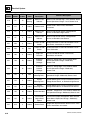
SAE Fastener Torque Chart (Continued)
Values for Magni Coating Fasteners (Ref 4150701)
SOCKET HEAD CAP SCREWS
Tensile Stress Clamp Load
Area
See Note 4
Size
TPI
Bolt Dia
In
Sq In
4
40
0.1120
0.00604
48
0.1120
0.00661
32
0.1380
0.00909
40
0.1380
0.01015
6
8
10
1/4
5/16
3/8
7/16
1/2
9/16
5/8
3/4
7/8
1
1 1/8
1 1/4
1 3/8
1 1/2
LB
Torque
(Dry) K=0.17
IN-LB
[N.m]
Torque
(Loctite® 242TM or 271TM or
Vibra-TITETM 111 or 140) or
Precoat® 85 K=0.16
IN-LB
[N.m]
Torque
(Loctite® 262TM or
Vibra-TITETM 131)
K=0.15
IN-LB
[N.m]
32
0.1640
0.01400
36
0.1640
0.01474
24
0.1900
0.01750
32
0.1900
0.02000
20
0.2500
0.0318
2860
122
14
114
13
28
0.2500
0.0364
3280
139
16
131
15
In
Sq In
LB
FT-LB
[N.m]
FT-LB
[N.m]
FT-LB
18
0.3125
0.0524
4720
20
25
20
25
20
25
24
0.3125
0.0580
5220
25
35
20
25
20
25
[N.m]
16
0.3750
0.0775
7000
35
50
35
50
35
50
24
0.3750
0.0878
7900
40
55
40
55
35
50
14
0.4375
0.1063
9550
60
80
55
75
50
70
20
0.4375
0.1187
10700
65
90
60
80
60
80
13
0.5000
0.1419
12750
90
120
85
115
80
110
20
0.5000
0.1599
14400
100
135
95
130
90
120
12
0.5625
0.1820
16400
130
175
125
170
115
155
18
0.5625
0.2030
18250
145
195
135
185
130
175
220
11
0.6250
0.2260
20350
180
245
170
230
160
18
0.6250
0.2560
23000
205
280
190
260
180
245
10
0.7500
0.3340
30100
320
435
300
415
280
380
16
0.7500
0.3730
33600
355
485
335
455
315
430
9
0.8750
0.4620
41600
515
700
485
660
455
620
14
0.8750
0.5090
45800
570
775
535
730
500
680
8
1.0000
0.6060
51500
730
995
685
930
645
875
12
1.0000
0.6630
59700
845
1150
795
1080
745
1015
7
1.1250
0.7630
68700
1095
1490
1030
1400
965
1310
12
1.1250
0.8560
77000
1225
1665
1155
1570
1085
1475
7
1.2500
0.9690
87200
1545
2100
1455
1980
1365
1855
12
1.2500
1.0730
96600
1710
2325
1610
2190
1510
2055
6
1.3750
1.1550
104000
2025
2755
1905
2590
1785
2430
12
1.3750
1.3150
118100
2300
3130
2165
2945
2030
2760
6
1.5000
1.4050
126500
2690
3660
2530
3440
2370
3225
12
1.5000
1.5800
142200
3020
4105
2845
3870
2665
3625
NOTES: 1. THESE TORQUE VALUES DO NOT APPLY TO CADMIUM PLATED FASTENERS
5000059K
2. ALL TORQUE VALUES ARE STATIC TORQUE MEASURED PER STANDARD AUDIT METHODS TOLERANCE = ±10%
3. * ASSEMBLY USES HARDENED WASHER
4. CLAMP LOAD LISTED FOR SHCS IS SAME AS GRADE 8 OR CLASS 10.9 AND DOES NOT REPRESENT FULL STRENGTH CAPABILITY OF SHCS.
IF HIGHER LOAD IS REQUIRED, ADDITIONAL TESTING IS REQUIRED.
G6-42A, G9-43A, G10-43A
2-7
General Information and Specifications
2.3.1
SAE Fastener Torque Chart (Continued)
Values for Zinc Yellow Chromate Fasteners (Ref 4150707)*
SOCKET HEAD CAP SCREWS
Tensile Stress Clamp Load
Area
See Note 4
Size
TPI
Bolt Dia
In
Sq In
4
40
0.1120
0.00604
48
0.1120
0.00661
32
0.1380
0.00909
40
0.1380
0.01015
6
8
10
1/4
5/16
3/8
7/16
Torque
(Dry) K=0.17
LB
IN-LB
[N.m]
Torque
(Loctite® 242TM or 271TM or
Vibra-TITETM 111 or 140) or
Precoat® 85 K=0.16
IN-LB
[N.m]
Torque
(Loctite® 262TM or
Vibra-TITETM 131)
K=0.15
IN-LB
[N.m]
32
0.1640
0.01400
36
0.1640
0.01474
24
0.1900
0.01750
32
0.1900
0.02000
20
0.2500
0.0318
2860
122
14
114
28
0.2500
0.0364
3280
139
16
131
15
In
Sq In
LB
FT-LB
[N.m]
FT-LB
[N.m]
FT-LB
18
0.3125
0.0524
4720
20
25
20
25
20
25
24
0.3125
0.0580
5220
25
35
20
25
20
25
16
0.3750
0.0775
7000
35
50
35
50
35
50
24
0.3750
0.0878
7900
40
55
40
55
35
50
70
13
[N.m]
14
0.4375
0.1063
9550
60
80
55
75
50
20
0.4375
0.1187
10700
65
90
60
80
60
80
1/2
13
0.5000
0.1419
12750
90
120
85
115
80
110
20
0.5000
0.1599
14400
100
135
95
130
90
120
9/16
12
0.5625
0.1820
16400
130
175
125
170
115
155
18
0.5625
0.2030
18250
145
195
135
185
130
175
5/8
11
0.6250
0.2260
20350
180
245
170
230
160
220
18
0.6250
0.2560
23000
205
280
190
260
180
245
3/4
10
0.7500
0.3340
30100
320
435
300
415
280
380
7/8
1
1 1/8
1 1/4
1 3/8
1 1/2
16
0.7500
0.3730
33600
355
485
335
455
315
430
9
0.8750
0.4620
41600
515
700
485
660
455
620
14
0.8750
0.5090
45800
570
775
535
730
500
680
8
1.0000
0.6060
51500
730
995
685
930
645
875
12
1.0000
0.6630
59700
845
1150
795
1080
745
1015
7
1.1250
0.7630
68700
1095
1490
1030
1400
965
1310
12
1.1250
0.8560
77000
1225
1665
1155
1570
1085
1475
7
1.2500
0.9690
87200
1545
2100
1455
1980
1365
1855
12
1.2500
1.0730
96600
1710
2325
1610
2190
1510
2055
6
1.3750
1.1550
104000
2025
2755
1905
2590
1785
2430
12
1.3750
1.3150
118100
2300
3130
2165
2945
2030
2760
6
1.5000
1.4050
126500
2690
3660
2530
3440
2370
3225
12
1.5000
1.5800
142200
3020
4105
2845
3870
2665
3625
NOTES: 1. THESE TORQUE VALUES DO NOT APPLY TO CADMIUM PLATED FASTENERS
5000059K
2. ALL TORQUE VALUES ARE STATIC TORQUE MEASURED PER STANDARD AUDIT METHODS TOLERANCE = ±10%
3. * ASSEMBLY USES HARDENED WASHER
4. CLAMP LOAD LISTED FOR SHCS IS SAME AS GRADE 8 OR CLASS 10.9 AND DOES NOT REPRESENT FULL STRENGTH CAPABILITY OF SHCS.
IF HIGHER LOAD IS REQUIRED, ADDITIONAL TESTING IS REQUIRED.
2-8
G6-42A, G9-43A, G10-43A
General Information and Specifications
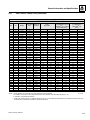
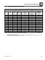
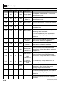
2.3.2
Metric Fastener Torque Chart
Values for Zinc Yellow Chromate Fasteners (Ref 4150707)*
CLASS 8.8 METRIC (HEX/SOCKET HEAD) BOLTS CLASS 8 METRIC NUTS
Tensile Stress Clamp Load
Area
See Note 4
Torque
(Dry or Loctite® 263TM)
Torque (Lub)
Torque
(Loctite® 262TM or
271TM or
Vibra-TITETM 131)
Torque
(Loctite® 242TM or
271TM or Vibra-TITETM
111 or 141)
[N.m]
[N.m]
Size
Pitch
Sq mm
KN
[N.m]
3
0.5
5.03
2.19
1.3
1.0
1.2
1.4
3.5
0.6
6.78
2.95
2.1
1.6
1.9
2.3
4
0.7
8.78
3.82
3.1
2.3
2.8
3.4
5
0.8
14.20
6.18
6.2
4.6
5.6
6.8
6
1
20.10
8.74
11
7.9
9.4
12
7
1
28.90
12.6
18
13
16
19
8
1.25
36.60
15.9
26
19
23
28
10
1.5
58.00
25.2
50
38
45
55
12
1.75
84.30
36.7
88
66
79
97
14
2
115
50.0
140
105
126
154
16
2
157
68.3
219
164
197
241
18
2.5
192
83.5
301
226
271
331
20
2.5
245
106.5
426
320
383
469
22
2.5
303
132.0
581
436
523
639
24
3
353
153.5
737
553
663
811
27
3
459
199.5
1080
810
970
1130
30
3.5
561
244.0
1460
1100
1320
1530
33
3.5
694
302.0
1990
1490
1790
2090
36
4
817
355.5
2560
1920
2300
2690
42
4.5
1120
487.0
4090
3070
3680
4290
NOTES: 1. THESE TORQUE VALUES DO NOT APPLY TO CADMIUM PLATED FASTENERS
5000059K
2. ALL TORQUE VALUES ARE STATIC TORQUE MEASURED PER STANDARD AUDIT METHODS TOLERANCE = ±10%
3. * ASSEMBLY USES HARDENED WASHER
4. CLAMP LOAD LISTED FOR SHCS IS SAME AS GRADE 8 OR CLASS 10.9 AND DOES NOT REPRESENT FULL STRENGTH CAPABILITY OF SHCS.
IF HIGHER LOAD IS REQUIRED, ADDITIONAL TESTING IS REQUIRED.
G6-42A, G9-43A, G10-43A
2-9
General Information and Specifications
2.3.2
Metric Fastener Torque Chart (Continued)
Values for Zinc Yellow Chromate Fasteners (Ref 4150707)*
CLASS 10.9 METRIC (HEX HEAD) BOLTS,
CLASS 10 METRIC NUTS CLASS 12.9 SOCKET HEAD CAP SCREWS M3 - M5*
Tensile Stress
Area
Clamp Load
See Note 4
Torque
(Dry or Loctite® 263TM)
K=0.20
Torque
(Lub or Loctite®
242TM or 271TM or
Vibra-TITETM 111 or 140)
K=0.18
Torque
(Loctite® 262TM or
Vibra-TITETM 131)
K=0.15
[N.m]
[N.m]
[N.m]
Size
Pitch
Sq mm
KN
3
0.5
5.03
3.13
3.5
0.6
6.78
4.22
4
0.7
8.78
5.47
5
0.8
14.20
8.85
6
1
20.10
12.5
7
1
28.90
18.0
25
23
19
8
1.25
36.60
22.8
37
33
27
10
1.5
58.00
36.1
70
65
55
12
1.75
84.30
52.5
125
115
95
14
2
115
71.6
200
180
150
16
2
157
97.8
315
280
235
18
2.5
192
119.5
430
385
325
20
2.5
245
152.5
610
550
460
22
2.5
303
189.0
830
750
625
24
3
353
222.0
1065
960
800
27
3
459
286.0
1545
1390
1160
30
3.5
561
349.5
2095
1885
1575
33
3.5
694
432.5
2855
2570
2140
36
4
817
509.0
3665
3300
2750
42
4.5
1120
698.0
5865
5275
4395
NOTES: 1. THESE TORQUE VALUES DO NOT APPLY TO CADMIUM PLATED FASTENERS
5000059K
2. ALL TORQUE VALUES ARE STATIC TORQUE MEASURED PER STANDARD AUDIT METHODS TOLERANCE = ±10%
3. * ASSEMBLY USES HARDENED WASHER
4. CLAMP LOAD LISTED FOR SHCS IS SAME AS GRADE 8 OR CLASS 10.9 AND DOES NOT REPRESENT FULL STRENGTH CAPABILITY OF SHCS.
IF HIGHER LOAD IS REQUIRED, ADDITIONAL TESTING IS REQUIRED.
2-10
G6-42A, G9-43A, G10-43A
General Information and Specifications
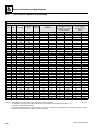
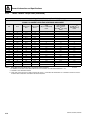
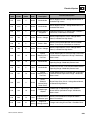
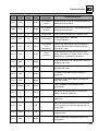
2.3.2
Metric Fastener Torque Chart (Continued)
Values for Magni Coated Fasteners (Ref 4150701)*
CLASS 8.8 METRIC (HEX/SOCKET HEAD) BOLTS CLASS 8 METRIC NUTS
Tensile Stress
Area
Clamp Load
See Note 4
Torque
(Dry or Loctite® 263TM)
K=0.17
Torque
(Lub or Loctite®
TM
242 or 271TM or
Vibra-TITETM 111 or 140)
K=0.16
Torque
(Loctite® 262TM or
Vibra-TITETM 131)
K=0.15
Size
Pitch
Sq mm
KN
[N.m]
[N.m]
[N.m]
3
0.5
5.03
2.19
1.1
1.1
1.0
3.5
0.6
6.78
2.95
1.8
1.7
1.5
4
0.7
8.78
3.82
2.6
2.4
2.3
5
0.8
14.20
6.18
5.3
4.9
4.6
6
1
20.10
8.74
9
8.4
7.9
7
1
28.90
12.6
15
14
13
8
1.25
36.60
15.9
22
20
19
10
1.5
58.00
25.2
43
40
38
12
1.75
84.30
36.7
75
70
66
14
2
115
50.0
119
110
105
165
16
2
157
68.3
186
175
18
2.5
192
83.5
256
240
225
20
2.5
245
106.5
362
340
320
22
2.5
303
132.0
494
465
435
24
3
353
153.5
627
590
555
27
3
459
199.5
916
860
810
30
3.5
561
244.0
1245
1170
1100
33
3.5
694
302.0
1694
1595
1495
36
4
817
355.5
2176
2050
1920
42
4.5
1120
487.0
3477
3275
3070
NOTES: 1. THESE TORQUE VALUES DO NOT APPLY TO CADMIUM PLATED FASTENERS
5000059K
2. ALL TORQUE VALUES ARE STATIC TORQUE MEASURED PER STANDARD AUDIT METHODS TOLERANCE = ±10%
3. * ASSEMBLY USES HARDENED WASHER
4. CLAMP LOAD LISTED FOR SHCS IS SAME AS GRADE 8 OR CLASS 10.9 AND DOES NOT REPRESENT FULL STRENGTH CAPABILITY OF SHCS.
IF HIGHER LOAD IS REQUIRED, ADDITIONAL TESTING IS REQUIRED.
G6-42A, G9-43A, G10-43A
2-11
General Information and Specifications
2.3.2
Metric Fastener Torque Chart (Continued)
Values for Magni Coated Fasteners (Ref 4150701)*
CLASS 10.9 METRIC (HEX HEAD) BOLTS CLASS 10 METRIC NUTS,
CLASS 12.9 SOCKET HEAD CAP SCREWS M6 AND ABOVE*
Tensile Stress
Area
Clamp Load See
Note 4
Torque
(Dry or Loctite® 263TM)
K=0.17
Torque
(Lub or Loctite®
242TM or 271TM or
Vibra-TITETM 111 or 140)
K=0.18
Torque
(Loctite® 262TM or
Vibra-TITETM 131)
K=0.15
[N.m]
[N.m]
[N.m]
11
Size
Pitch
Sq mm
KN
3
0.5
5.03
3.13
3.5
0.6
6.78
4.22
4
0.7
8.78
5.47
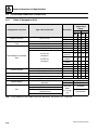
5
0.8
14.20
8.85
6
1
20.10
12.5
13
12
7
1
28.90
18.0
21
20
19
8
1.25
36.60
22.8
31
29
27
10
1.5
58.00
36.1
61
58
55
12
1.75
84.30
52.5
105
100
95
14
2
115
71.6
170
160
150
16
2
157
97.8
265
250
235
18
2.5
192
119.5
365
345
325
20
2.5
245
152.5
520
490
460
22
2.5
303
189.0
705
665
625
24
3
353
222.0
905
850
800
27
3
459
286.0
1315
1235
1160
30
3.5
561
349.5
1780
1680
1575
33
3.5
694
432.5
2425
2285
2140
36
4
817
509.0
3115
2930
2750
42
4.5
1120
698.0
4985
4690
4395
NOTES: 1. THESE TORQUE VALUES DO NOT APPLY TO CADMIUM PLATED FASTENERS
5000059K
2. ALL TORQUE VALUES ARE STATIC TORQUE MEASURED PER STANDARD AUDIT METHODS TOLERANCE = ±10%
3. * ASSEMBLY USES HARDENED WASHER
4. CLAMP LOAD LISTED FOR SHCS IS SAME AS GRADE 8 OR CLASS 10.9 AND DOES NOT REPRESENT FULL STRENGTH CAPABILITY OF SHCS.
IF HIGHER LOAD IS REQUIRED, ADDITIONAL TESTING IS REQUIRED.
2-12
G6-42A, G9-43A, G10-43A
General Information and Specifications
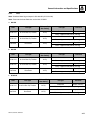
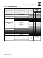
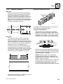
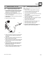
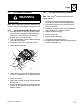
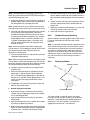
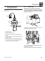
2.3.3
Hydraulic Hose Torque Chart
O-Ring Face Seal & JIC Torque Chart
Flats Method:
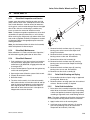
1. If equipped, lubricate o-ring with hydraulic oil. Hand
tighten the swivel nut until no lateral movement of
the swivel nut can be detected. Average hand torque
is 3 lb-ft (4 Nm).
Size
ORFS
JIC
Flats Method
4
13 lb-ft
(18 Nm)
13 lb-ft
(18 Nm)
1.5 to 1.75
2. Mark a dot on one of swivel nut flats and another dot
in line on hex of adapter it’s connecting to.
6
23 lb-ft
(31 Nm)
23 lb-ft
(31 Nm)
1 to 1.5
3. Use double wrench method while tightening to avoid
hose twist.
8
40 lb-ft
(54 Nm)
40 lb-ft
(54 Nm)
1.5 to 1.75
10
60 lb-ft
(81 Nm)
60 lb-ft
(81 Nm)
1.5 to 1.75
12
136 lb-ft
(100 Nm)
136 lb-ft
(100 Nm)
1.0 to 1.5
16
115 lb-ft
(156 Nm)
115 lb-ft
(156 Nm)
0.75 to 1.0
20
170 lb-ft
(230 Nm)
170 lb-ft
(230 Nm)
0.75 to 1.0
24
200 lb-ft
(271 Nm)
200 lb-ft
(271 Nm)
0.75 to 1.0
32
N/A
270 lb-ft
(366 Nm)
0.75 to 1.0
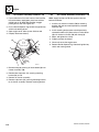
4. After connection has been properly tightened, mark
a straight line across the connecting parts, not
covering dots indicating that connection has been
properly tightened.
Note: By definition the “Flats Method” will contain some
variance. Use the “Flats Method” only when accessibility
with a torque wrench is not possible.
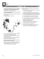
Torque Wrench:
1. Identify the appropriate application and refer to the
above chart for the correct torque value.
2. If equipped, lubricate o-ring with hydraulic oil. Hand
tighten the swivel nut until no lateral movement of
the swivel nut can be detected. Average hand torque
is 3 lb-ft (4 Nm).
3. Use the double wrench method while tightening to
avoid hose twist.
4. Torque wrench must be held at the center of the grip.
Apply constant force until it clicks.
5. After connection has been properly tightened, mark
a straight line across connecting parts indicating that
connection has been properly tightened.
G6-42A, G9-43A, G10-43A
2-13
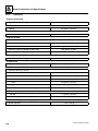
General Information and Specifications
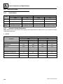
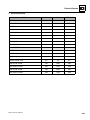
2.4
SPECIFICATIONS
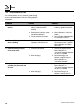
2.4.1
Travel Speeds
G6-42A
Gear
G9-43A & G10-43A
ULS
LS
ULS
LS
First
3.8 mph (6,1 km/h)
3.4 mph (6,1 km/h)
3.4 mph (5,5 km/h)
3.5 mph (5,6 km/h)
Second
6.8 mph (12,9 km/h)
6.8 mph (10,9 km/h)
6.1 mph (9,8 km/h)
6.3 mph (10,1 km/h)
Third
15.5 mph (25,9 km/h)
15.1 mph (24,3 km/h)
13.9 mph (22,4 km/h)
14.2 mph (22,9 km/h)
Fourth
23.2 mph (32,9 km/h)
22.2 mph (35,7 km/h)
19.8 mph (31,9 km/h)
18.3 mph (29,5 km/h)
2.4.2
Hydraulic Cylinder Performance
Note: Machine with no attachment or load, engine at full throttle, hydraulic oil above 130° F (54° C) minimum, engine
at operating temperature.
a. G6-42A
Approximate Times (seconds)
Function
ULS
LS
Min Time
Max Time
Min Time
Max Time
Boom Extend (Boom Level)
13.6
14.7
14.0
14.8
Boom Retract
7.41
14.8
12.3
13.1
Boom Lift
11.9
12.8
12.6
13.4
Boom Lower
8.8
9.0
9.2
10.0
Attachment Tilt Forward
3.8
3.8
3.4
3.9
Attachment Tilt Rearward
3.2
3.2
3.9
4.4
Frame Level - Full Right to Left
7.4
7.4
6.3
6.9
Frame Level - Full Left to Right
5.8
5.8
8.6
9.6
2-14
G6-42A, G9-43A, G10-43A
General Information and Specifications
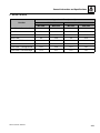
b. G9-43A & G10-43A
Approximate Times (seconds)
Function
ULS
LS
Min Time
Max Time
Min Time
Max Time
Boom Extend (Boom Level)
14.4
16.5
14.4
15.9
Boom Retract
11.0
20.0
16.8
18.6
Boom Lift
10.2
12.4
11.3
12.5
Boom Lower
9.3
14.0
9.2
10.2
Attachment Tilt Forward
6.0
8.5
7.2
8.0
Attachment Tilt Rearward
6.0
9.0
6.8
7.5
Frame Level - Full Right to Left
10.5
13.0
11.9
13.1
Frame Level - Full Left to Right
10.9
12.1
11.0
12.1
G6-42A, G9-43A, G10-43A
2-15
General Information and Specifications
2.4.3
Electrical SystemEngine System
Battery (if equipped for ULS)
Type, Rating
12 BCI, Negative (-) Ground, Maintenance Free
Cold Cranking Amps @ 0° F (-18° C)
950
Cranking Amps @ 32° F (-18° C)
1190
Reserve Capacity Minutes @ 25 Amps
185
Group/Series
Group 31
Alternator
12V, 120 Amps
Battery (if equipped for LS)
Type, Rating
12 BCI, Negative (-) Ground, Maintenance Free
Cold Cranking Amps @ 0° F (-18° C)
700
Cranking Amps @ 32° F (-18° C)
840
Reserve Capacity Minutes @ 25 Amps
180
Group/Series
Group 31
Alternator
12V, 120 Amps
Battery: Arctic if Equipped (2)
Type, Rating
12 BCI, Negative (-) Ground, Maintenance Free
Cold Cranking Amps @ 0° F (-18° C)
750
Cranking Amps @ 32° F (-18° C)
1000
Reserve Capacity Minutes @ 25 Amps
310
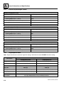
2.4.4
Engine Specifications
Note: Engine manufacturer's maximum “high idle” setting is lockwired and sealed. DO NOT disturb this setting
Description
G6-42A, G9-43A & G10-43A
If Equipped for ULS
If Equipped for LS
Engine Make/Model
Cummins QSB3.3
Cummins QSB3.3
Displacement
201 in³ (3,3 liters)
201 in³ (3,3 liters)
Low Idle
1000 rpm
1000 rpm
High Idle
2600 rpm
2600 rpm
Horsepower
100 HP (74,6 kW) @ 2600 rpm
99 HP (74 kW) @ 2600 rpm
Peak Torque
306 lb-ft (415 Nm) @ 1600 rpm
306 lb-ft (415 Nm) @ 1600 rpm
Fuel Delivery
Air Cleaner
2-16
Fuel Injection
Dry Type, Replaceable Primary and Safety Elements
G6-42A, G9-43A, G10-43A
General Information and Specifications
2.4.5
Tires
Note: Standard wheel lug nut torque is 350–400 lb-ft (475–542 Nm)
Note: Pressures for foam filled tires are for initial fill ONLY.
a. G6-42A
Size
Tire Type
Minimum Ply/
Star Rating
13.00 x 24
G-2/L-2 Bias Ply Traction
12 Ply
15.50 x 25
G-2/L-2 Bias Ply Traction
12 Ply
370/75-28
DuraForce
14 Ply
Size
Tire Type
Minimum Ply/
Star Rating
13.00 x 24
G-2/L-2 Bias Ply Traction
12 Ply
15.50 x 25
G-2/L-2 Bias Ply Traction
12 Ply
370/75-28
DuraForce
14 Ply
Fill Type
Pressure
Pneumatic
65 psi (4,5 bar)
Foam—Approximately 542 lb (246 kg)
Pneumatic
58 psi (4,0 bar)
Foam—Approximately 600 lb (272 kg)
Pneumatic
76 psi (5,2 bar)
Foam—Approximately 464 lb (210 kg)
b. G9-43A
Fill Type
Pressure
Pneumatic
65 psi (4,5 bar)
Foam—Approximately 542 lb (246 kg)
Pneumatic
65 psi (4,0 bar)
Foam—Approximately 600 lb (272 kg)
Pneumatic
76 psi (5,2 bar)
Foam—Approximately 464 lb (210 kg)
c. G10-43A
Size
Tire Type
Minimum Ply/
Star Rating
14.00 x 24
G-2/L-2 Bias Ply Traction
12 Ply
400/75-28
DuraForce
14 Ply
G6-42A, G9-43A, G10-43A
Fill Type
Pressure
Pneumatic
65 psi (4,8 bar)
Foam—Approximately 720 lb (327 kg)
Pneumatic
76 psi (5,2 bar)
Foam—Approximately 570 lb (259 kg)
2-17
General Information and Specifications
2.5
2.5.1
FLUID AND LUBRICANT CAPACITIES
Fluids (if Equipped for ULS)
Compartment or System
Type and Classification
Engine Crankcase
API CJ-4 Plus
Transmission and Transfer
Case
Mobilfluid 424
Mobilfluid LT
Mobilfluid 424
Mobilfluid LT
Axle Differential and Wheel
End
Hydraulic System
Boom Wear Pad Grease
Cylinder and Axle Grease
Boom Chain Lubricant
Engine Coolant
Fuel
API GL4 with
LS Additives
or
API GL5 with
LS Additives
Ambient
Temperature
Range
Viscosities
°F
°C
Ma
Ma
Min
Min
x
x
SAE 15W-40
5 120 -15 49
SAE 0W-40 -40 0 -40 -20
10W-30
0 104 -20 40
75W-80
-40 0 -40 -20
10W-30
0 104 -20 40
75W-80
-40 0 -40 -20
SAE140
80W-140
85W-140
SAE90
SAE90LS
80W-90
85W-90
75W-90
75W
50
122
10
50
14
122
-10
50
32
104
0
40
-4
104
-20
40
-40
-40
104
50
-40
-40
40
10
Mobilfluid 424
10W-30
0 104 -20 40
Exxon Univis HVI
-40 0 -40 -20
Mystik Tetrimoly
NLGI Grade 2 -4 104 -20 40
Multipurpose Grease
NLGI Grade 2 -22 104 -30 40
Schaffer 200S Silver Streak
50/50 Mix
Standard
Ethylene Glycol
and Water
60/40 Mix
Cold Weather
#2 Diesel
Standard
Ultra Low
B5 Biodiesel
Sulfur
Blend #1 diesel and #2 diesel fuels
(S ≤ 15 mg/
("winterized" #2)
Cold Weather
kg)
B5 Biodiesel with Winter Conditioner
Note: Friction Modifier may be added to front axle differentials, see Section 2.5.3, “Capacities.”
2-18
G6-42A, G9-43A, G10-43A
General Information and Specifications
2.5.2
Fluids (if Equipped for LS)
Compartment or System
Type and Classification
Engine Crankcase
API CI-4 Multigrade
Transmission and Transfer
Case
Mobilfluid 424
Mobilfluid LT
Mobilfluid 424
Mobilfluid LT
Axle Differential and Wheel
End
Hydraulic System
Boom Wear Pad Grease
Cylinder and Axle Grease
Boom Chain Lubricant
Engine Coolant
Fuel
API GL4 with
LS Additives
or
API GL5 with
LS Additives
Ambient
Temperature
Range
Viscosities
°F
°C
Ma
Ma
Min
Min
x
x
SAE 15W-40
5 120 -15 49
SAE 0W-40 -40 0 -40 -20
10W-30
0 104 -20 40
75W-80
-40 0 -40 -20
10W-30
0 104 -20 40
75W-80
-40 0 -40 -20
SAE140
80W-140
85W-140
SAE90
SAE90LS
80W-90
85W-90
75W-90
75W
50
122
10
50
14
122
-10
50
32
104
0
40
-4
104
-20
40
-40
-40
104
50
-40
-40
40
10
Mobilfluid 424
10W-30
0 104 -20 40
Exxon Univis HVI
-40 0 -40 -20
Mystik Tetrimoly
NLGI Grade 2 -4 104 -20 40
Multipurpose Grease
NLGI Grade 2 -22 104 -30 40
Schaffer 200S Silver Streak
50/50 Mix
Standard
Ethylene Glycol
and Water
60/40 Mix
Cold Weather
#2 Diesel
Standard
B5 Biodiesel
Low Sulfur
(S ≤ 500 mg/
Blend #1 diesel and #2 diesel fuels
kg)
("winterized" #2)
Cold Weather
B5 Biodiesel with Winter Conditioner
Note: Friction Modifier may be added to front axle differentials, see Section 2.5.3, “Capacities.”
G6-42A, G9-43A, G10-43A
2-19
General Information and Specifications
2.5.3
Capacities
Engine Crankcase Oil
Capacity with Filter Change
8.0 quarts (7,6 liters)
Fuel Tank
Capacity
38 gallons (144 liters)
Cooling System
System Capacity
15 quarts (14,2 liters)
Hydraulic System
System Capacity
G6-42A
43 gallons (163 liters)
G9-43A & G10-43A
44 gallons (168 liters)
Reservoir Capacity to Middle of Sight Gage
Auxiliary Hydraulic Circuit Max Flow
24.5 gallons (93 liters)
Not Available at Publication
Transmission
Capacity with Filter Change
16 quarts (15,1 liters)
Transfer Case
Capacity
2.1 quarts (2,0 liters)
Axles
Differential Housing Capacity
G6-42A
Friction Modifier (Front differential only)
8.5 quarts (8 liters)
13.6 ounces (402,2 milliliter)
G9-43A & G10-43A
Front
8.2 quarts (7,8 liters)
Rear
13 quarts (12,3 liters)
Friction Modifier (Front differential only)
13.12 ounces (372,7 milliliter)
Wheel End Capacity
G6-42A
G9-43A & G10-43A
1.7 quarts (1,6 liters)
1.75 quarts (1,65 liters)
Air Conditioning System (if equipped)
System Capacity
2-20
2.5 lb (1134 g)
G6-42A, G9-43A, G10-43A
General Information and Specifications
2.6
2.6.1
SERVICE AND MAINTENANCE
SCHEDULE
10, 1st 50 & 50 Hour
EVERY
10
Air Filter
Restriction
Indicator
Check Fuel
Level
Check Engine
Oil Level
Check Hydraulic
Oil Level
Check Tire
Condition &
Pressure
Check
Battery
Check Washer
Fluid Level
(if equipped)
Lubrication
Schedule
Check
Transmission
Oil Level
1st
50
LB/F
T (N
m)
Check Wheel
Lug Nut
Torque
EVERY
50
Drain Fuel/
Water
Separator
Check Engine
Coolant Level
MY7680
G6-42A, G9-43A, G10-43A
2-21
General Information and Specifications
2.6.2
1st 250, 250 & 500 Hour
1st
250
Change
Axle Oil
Change Wheel
End Oil
Change
Transmission
Oil & Filter
Change
Transfer Case
Oil
EVERY
250
Change Engine
Oil and Filter
Check Axle
Oil Level
Check Wheel
End Oil Levels
Air Filter
Vacuator
Valve
Check Boom
Wear Pads
Check Transfer
Case Oil Level
Check
Rear Axle
Stabilization
Lubrication
Schedule
Check
Fan Belt
EVERY
500
LB/F
T (N
m)
Change Fuel
Filters
Check Wheel
Lug Nut
Torque
OY3430
2-22
G6-42A, G9-43A, G10-43A
General Information and Specifications
2.6.3
1000, 1500 & 2000 Hour
EVERY
1000
Change
Transmission
Oil & Filter
Change
Transfer Case
Oil
Check
Boom Chains
Lubrication
Schedule
Change
Axle Oil
Change Wheel
End Oil
Check
Air Intake
System
EVERY
1500
Change
Hydraulic
Fluid & Filters
Change
Hydraulic Tank
Breather
EVERY
2000
Change Crankcase
Vent Filter (if
equipped for ULS)
Engine
Valve Lash
Adjustment
Change
Engine Coolant
OY3440
G6-42A, G9-43A, G10-43A
2-23
General Information and Specifications
2.7
2.7.1
LUBRICATION SCHEDULE
50 Hour
EVERY
50
G10-43A
2
B
B
2
2
2
B
B
2
B
B
2
B
2
B
2
2
2
2
2
2
4
2
2
2
G10-43A
OY2550
2-24
G6-42A, G9-43A, G10-43A
General Information and Specifications
2.7.2
250 Hour
EVERY
250
2
B
2
B
B
2
B
2
2
B
B
2
B
B
2
2
A
A
A
2
A
A
A
A
A
A
2
2
2
A
G10-43A
OY2560
G6-42A, G9-43A, G10-43A
2-25
General Information and Specifications
2.7.3
1000 Hour
EVERY
1000
B
B
G10-43A
OY2570
2-26
G6-42A, G9-43A, G10-43A
Section 3
Boom
Contents
PARAGRAPH
3.1
3.2
3.3
3.4
3.5
3.6
3.7
3.8
TITLE
PAGE
Boom System Component Terminology . . . . . . . . . . . . . . . . . . . . . . . . . . . . . . . .
Boom System—Three Section . . . . . . . . . . . . . . . . . . . . . . . . . . . . . . . . . . . . . . . .
3.2.1
Boom System Operation . . . . . . . . . . . . . . . . . . . . . . . . . . . . . . . . . . . . . .
Boom Assembly Maintenance . . . . . . . . . . . . . . . . . . . . . . . . . . . . . . . . . . . . . . . .
Complete Boom Removal/Installation. . . . . . . . . . . . . . . . . . . . . . . . . . . . . . . . . .
3.4.1
Complete Boom Removal . . . . . . . . . . . . . . . . . . . . . . . . . . . . . . . . . . . . .
3.4.2
Complete Boom Installation . . . . . . . . . . . . . . . . . . . . . . . . . . . . . . . . . . .
Boom Section Removal/Installation . . . . . . . . . . . . . . . . . . . . . . . . . . . . . . . . . . .
3.5.1
Second and Third Boom Section Removal . . . . . . . . . . . . . . . . . . . . . . . .
3.5.2
Third Boom Section Removal . . . . . . . . . . . . . . . . . . . . . . . . . . . . . . . . . .
3.5.3
Push Beam—Extend/Retract Cylinder Removal. . . . . . . . . . . . . . . . . . . .
3.5.4
Push Beam—Extend/Retract Cylinder Installation and Third Boom Section
Assembly. . . . . . . . . . . . . . . . . . . . . . . . . . . . . . . . . . . . . . . . . . . . . . . . . .
3.5.5
Third Boom Section Installation . . . . . . . . . . . . . . . . . . . . . . . . . . . . . . . .
3.5.6
Second and Third Boom Section Installation . . . . . . . . . . . . . . . . . . . . . .
Extend/Retract Chain Removal/Installation . . . . . . . . . . . . . . . . . . . . . . . . . . . . .
3.6.1
Extend/Retract Chain Removal. . . . . . . . . . . . . . . . . . . . . . . . . . . . . . . . .
3.6.2
Extend/Retract Chain Installation . . . . . . . . . . . . . . . . . . . . . . . . . . . . . . .
Push Beam—Extend/Retract Cylinder Removal/Installation . . . . . . . . . . . . . . .
3.7.1
Push Beam Extend/Retract Cylinder Removal . . . . . . . . . . . . . . . . . . . . .
3.7.2
Push Beam—Extend/Retract Cylinder Installation . . . . . . . . . . . . . . . . . .
Boom Adjustments . . . . . . . . . . . . . . . . . . . . . . . . . . . . . . . . . . . . . . . . . . . . . . . . .
3.8.1
Chain Tension Inspection—G6-42A . . . . . . . . . . . . . . . . . . . . . . . . . . . . .
3.8.2
Chain Tension Adjustment—G6-42A . . . . . . . . . . . . . . . . . . . . . . . . . . . .
3.8.3
Chain Tension Inspection— G9-43A/G10-43A . . . . . . . . . . . . . . . . . . . . .
3.8.4
Chain Tension Adjustment— G9-43A/G10-43A . . . . . . . . . . . . . . . . . . . .
G6-42A, G9-43A, G10-43A
3-3
3-4
3-4
3-4
3-5
3-5
3-5
3-6
3-6
3-7
3-9
3-9
3-11
3-13
3-15
3-15
3-15
3-16
3-16
3-18
3-20
3-20
3-21
3-23
3-23
3-1
Boom
3.9
3.10
3.11
3.12
3.13
3.14
3.15
3-2
Quick Switch Assembly . . . . . . . . . . . . . . . . . . . . . . . . . . . . . . . . . . . . . . . . . . . . .
3.9.1
Hydraulic Quick Switch Removal . . . . . . . . . . . . . . . . . . . . . . . . . . . . . . .
3.9.2
Quick Switch Removal . . . . . . . . . . . . . . . . . . . . . . . . . . . . . . . . . . . . . . .
3.9.3
Quick Switch Installation . . . . . . . . . . . . . . . . . . . . . . . . . . . . . . . . . . . . . .
Boom Wear Pads . . . . . . . . . . . . . . . . . . . . . . . . . . . . . . . . . . . . . . . . . . . . . . . . . . .
3.10.1
Wear Pad Inspection . . . . . . . . . . . . . . . . . . . . . . . . . . . . . . . . . . . . . . . . .
3.10.2
Wear Pad Installation and Lubrication . . . . . . . . . . . . . . . . . . . . . . . . . . .
3.10.3
Boom Section Wear Pad Pathway Lubrication: . . . . . . . . . . . . . . . . . . . .
Boom Extend and Retract Chains . . . . . . . . . . . . . . . . . . . . . . . . . . . . . . . . . . . . .
3.11.1
Boom Chain Inspection . . . . . . . . . . . . . . . . . . . . . . . . . . . . . . . . . . . . . . .
3.11.2
Expose Chains for Inspection . . . . . . . . . . . . . . . . . . . . . . . . . . . . . . . . . .
3.11.3
Inspection Guidelines . . . . . . . . . . . . . . . . . . . . . . . . . . . . . . . . . . . . . . . .
3.11.4
Chain Lubrication . . . . . . . . . . . . . . . . . . . . . . . . . . . . . . . . . . . . . . . . . . .
Forks. . . . . . . . . . . . . . . . . . . . . . . . . . . . . . . . . . . . . . . . . . . . . . . . . . . . . . . . . . . . .
Emergency Boom Lowering Procedure . . . . . . . . . . . . . . . . . . . . . . . . . . . . . . . .
3.13.1
Equipment and Supplies Required . . . . . . . . . . . . . . . . . . . . . . . . . . . . . .
3.13.2
Lowering Procedure . . . . . . . . . . . . . . . . . . . . . . . . . . . . . . . . . . . . . . . . .
Troubleshooting . . . . . . . . . . . . . . . . . . . . . . . . . . . . . . . . . . . . . . . . . . . . . . . . . . .
Push Beam Temporary Brackets . . . . . . . . . . . . . . . . . . . . . . . . . . . . . . . . . . . . . .
3-25
3-25
3-26
3-26
3-26
3-26
3-26
3-27
3-28
3-28
3-28
3-29
3-30
3-31
3-31
3-31
3-32
3-34
3-37
G6-42A, G9-43A, G10-43A
Boom
3.1
BOOM SYSTEM
COMPONENT TERMINOLOGY
The following illustrations identify the components that
are referred to throughout this section.
SECOND BOOM
SECTION
EXTEND CHAIN
(INSIDE BOOM)
THIRD
BOOM
SECTION
FIRST BOOM
SECTION
PUSH BEAM
ASSEMBLY
RETRACT CHAIN
(INSIDE BOOM)
QUICK
SWITCH
TILT
CYLINDER
EXTEND/RETRACT
CYLINDER
(INSIDE PUSH BEAM)
STRONG BACK
HOSE SHEAVE
(INSIDE BOOM)
MY7730
PIVOT PIN
G6-42A, G9-43A, G10-43A
3-3
Boom
3.2
3.2.1
BOOM SYSTEM—THREE SECTION
Boom System Operation
The three section boom consists of the first, second and
third assemblies with a single extend chain, and a single
retract chain.
As the extend/retract cylinder, which is anchored at the
rear of the first boom section, and the front of the push
beam begins to extend, it forces the second and third
boom sections out of the first boom section.
The boom sections are connected by extend and retract
chains. These chains are routed around sheaves on the
front of the push beam and the rear of the second boom
section. As the extend/retract cylinder is forced out
hydraulically, the second boom section is pulled out by
the push beam, and third boom section is pulled out by
the extend chain.
As hydraulic pressure is applied to the retract port on the
extend/retract cylinder, the retract chain pulls the third
boom section and the push beam pulls the second boom
section back into the first boom section.
The mechanical linkage formed by the chains and
supporting hardware, extend and retracts the second and
third boom sections at the same rate.
The boom section lifts and lowers via action of the lift/
lower cylinder.
3.3
BOOM ASSEMBLY MAINTENANCE
These instructions provide the complete boom assembly
removal and installation or the second and third boom
sections removal and installation.
Before beginning, conduct a visual inspection of machine
and work area, and review task about to be undertaken.
Read, understand and follow these instructions. Boom
assembly consists of first, second and third section
booms and supporting hardware.
Note: Before removing the boom or boom section, the
carriage or any other attachment must be removed from
the quick switch.
Before beginning, conduct a visual inspection of machine
and work area, and review task about to be undertaken.
Read, understand and follow these instructions.
During service of the boom, perform the following:
1. Check wear pads. (Refer to Section 3.10, “Boom
Wear Pads.”)
2. Check hose sheaves and chain rollers.
3. Apply grease at all lubrication points (grease fittings).
(Refer to Section 2.6, “Lubrication Schedules.”)
4. Check for the proper operation by operating all the
boom functions through their full ranges of motion
several times.
Note: Depending on your particular circumstance, the
following procedures explain the removal/installation of
individual boom sections or removal/installation of the
complete boom.
WARNING
NEVER weld or drill the boom unless approved in
writing by the manufacturer. The structural integrity of
the boom will be impaired if subjected to any repair
involving welding or drilling.
3-4
G6-42A, G9-43A, G10-43A
Boom
3.4
COMPLETE BOOM REMOVAL/
INSTALLATION
3.4.1
Complete Boom Removal
1. Remove any attachment from quick switch assembly.
3.4.2
Complete Boom Installation
1. Using suitable slings, balance the boom assembly,
lift and carefully guide the boom into place. Align the
frame pivot bore with the boom assembly pivot bore.
Install the boom pivot pin (1).
2. Remove the quick switch assembly. Refer to Section
3.9, “Quick Switch Assembly.”
2. With the sling still in place, install the compensation
cylinder, pins and bolts. Apply Loctite® 242TM and
torque lock bolt to 100-110 lb-ft (135-149 Nm).
3. Park machine on a hard, level surface, level
machine, fully retract boom, level boom, place
transmission control lever in (N) NEUTRAL,
engage park brake and shut engine OFF.
3. With the sling still in place, install the rod end of the
lift/lower cylinder, pin and lock bolt. Apply Loctite®
242TM and torque lock bolt to 200-215 lb-ft
(271-291 Nm).
4. Place a Do Not Operate Tag on both the ignition key
switch and the steering wheel.
5. Open engine cover. Allow system fluids to cool.
6. Properly disconnect battery.
7. Using a suitable sling or hoist, support the boom.
8. Label, disconnect and cap the hydraulic hoses at the
rear of the boom. Cap all fittings to keep dirt and
debris from entering the hydraulic system.
9. Label and disconnect any electrical cables
(if equipped) at the rear of the boom.
10. Remove the pin from the rod end of the
compensation cylinder being careful not to drop the
cylinder. Lower the cylinder onto the frame rails.
11. Remove the pin from the rod end of the lift/lower
cylinder. Lower the cylinder onto the frame rails.
Note: Raising boom up or down with sling my be
necessary so boom, compensation and lift/lower cylinder
bores can be aligned for easier pin installation.
Note: Grease the boom pivot bore, compensation
cylinder rod end, lift/lower cylinder rod end and pins
before installing.
4. Uncap and reconnect the previously labeled
hydraulic hoses to the extend/retract cylinder.
5. Uncap and connect and remaining hydraulic fittings
to their appropriate locations.
6. Recheck wear pad gaps to ensure they meet the
minimum gap requirement. Shim if necessary.
7. Ensure that the boom chains are properly adjusted.
Refer to Section 3.8, “Boom Adjustments.”
8. Properly connect the battery.
9. Install the quick switch assembly. Refer to Section
3.9, “Quick Switch Assembly.”
10. Start engine and operate all boom functions several
times. Check for leaks, and check hydraulic fluid
level in reservoir; add fluid if required.
11. Clean up all debris, hydraulic fluid, etc., in, on, near
and around the machine.
12. Close and secure the engine cover.
MY1520
1
12. Confirm that boom assembly is balanced with sling
and remove the boom assembly pivot pin (1).
13. Remove Do Not Operate Tags from both ignition key
switch and the steering wheel.
14. Install the previously removed attachment to the
quick switch assembly.
13. Lift boom assembly from machine and lower onto
suitable supports.
G6-42A, G9-43A, G10-43A
3-5
Boom
3.5
BOOM SECTION
REMOVAL/INSTALLATION
3.5.1
4. Slowly loosen and remove the extend/retract
cylinder counterbalance valve (3). Plug (M27x1.5)
open port on extend/retract cylinder to prevent dirt
and debris from entering hydraulic system.
Second and Third Boom
Section Removal
5. Remove retaining clips from extend/retract cylinder
mounting pin (4), remove extend/retract cylinder pin.
Note: Refer to Section 3.13.2, 3.15. “Push Beam
Temporary Brackets,” for diagrams of the Temporary
Extend Bracket and Temporary Retract Bracket
designed to hold the chains in place on the push beam
during disassembly and reassembly.
These brackets are NOT a purchasable part and must be
manufactured locally.
They are solely designed to aid in the removal and
installation of the push beam assembly.
6. Remove four mounting bolts securing the strong
back (5) to the first boom section.
7. Remove strong back (5) from rear of boom.
8. Remove right or left side wear pads, shims and
backing plates (6) from rear of second boom section.
Label and tag each set of wear pads being removed.
9. Remove the top wear pads, shims and backing
plates (7) from the rear of the second boom section.
Label and tag each set of wear pads being removed.
Note: Refer to Section 8.8, “Hydraulic Cylinders.” for
general tilt cylinder removal.
1. Remove the access cover from the rear of the first
boom section.
7
8
11
9
10
G6-42A
7
1
8
5
4
MY3860
3
G9-43A
G10-43A
2
2
6
6
10. Loosen and remove the four bolts (8) securing the
retract chain anchor plate (9).
11. Between bottom front of first and second boom
sections, feed a rope or wire to retract chain anchor
plate and secure to second or third boom section.
12. Disconnect both tilt tubes (10) and (if equipped) both
auxiliary tubes from fittings on hose retainer brackets
(11) at bottom front inside the boom. Plug the tube
ends to prevent dirt and debris from entering the
hydraulic system.
MAL2660
2. Remove the locknut, adjustment nut and six
belleville washers (1) from the extend chain clevis
rod at the rear of the boom.
3. Loosen and remove both extend/retract cylinder
tubes (2) from rear of boom. Cap and/or plug all
open hoses, tubes and/or fittings to prevent dirt and
debris from entering the hydraulic system.
3-6
13. Disconnect both tilt hoses (not shown) and (if
equipped) both auxiliary hoses from hose retainer
brackets at bottom front inside the boom. Plug hose
ends to prevent dirt and debris from entering the
hydraulic system.
14. Loosen and remove the hose retainer brackets (11)
and (if equipped) both auxiliary take-up brackets.
G6-42A, G9-43A, G10-43A
Boom
15. Between bottom front of first and second boom
sections, feed a rope or wire to both tilt hoses (not
shown) and (if equipped) both auxiliary hoses and
secure to the second or third boom section.
3.5.2
Third Boom Section Removal
16. Place a suitable sling around the second boom
section. Slowly pull the second and third boom
sections approximately 25% out of the first boom
section. Lower the second and third boom sections
onto a suitable support.
1
1
2
12
13
12
MY3880
1. Loosen and remove the tilt cylinder hose guide (1)
and if equipped, the auxiliary hose guide from the
rear of the third second section.
12
13
Note: The hose guide mounting bolts also hold the push
pin beams in place.
12
MY3840
17. Remove all wear pads, shims and backing plates
(12) from the front inside of the first boom section.
Label and tag each set of wear pads being removed.
2. Loosen and remove all retract chain sheave
components (2) and the hydraulic hose rollers
and components.
Note: Offset the extend chain rod to the left or right of
the push beam assembly allowing the push beam to be
raised enough to allow the removal of the chain and
hose sheaves.
18. Remove the top and bottom mounting plates (13)
from the front inside of the first boom section. Label
and tag each mounting plate being removed.
19. Relocate sling or using two slings for better stability,
balance two boom sections and slowly pull them out
of first boom section being careful not to damage
hydraulic hoses or chains. Lower second and third
boom sections onto suitable supports.
3
4
5
6
MY4070
3. Attach the Temporary Extend Chain Retention
Bracket (3) between the extend chain rod (4) and the
push beam tube (5). Snug in place. Do Not tighten.
Note: Refer to Section 3.15, “Push Beam Temporary
Brackets,” for Temporary Extend Chain Bracket diagram.
4. At the rear of the boom, remove the retract chain (6)
from the chain clevis.
G6-42A, G9-43A, G10-43A
3-7
Boom
12
11
8
11
7
12
11
11
MY4110
MY3870
5. Loosen and remove the tilt hoses and (if equipped)
auxiliary hoses from the hose retainers (7 & 8) at the
front of the third boom section.
6. Loosen and remove tilt hose and auxiliary hose
retainers (7 & 8) from front of third boom section.
10
10
9
10. Remove all wear pads, shims and backing
plates (11) from front inside of second boom section.
Label and tag each set of wear pads being removed.
11. Remove wear pad mounting plates (12) from front
inside of second boom section.
12. Relocate sling or using two slings for better stability,
balance third boom section and slowly pull third
boon section out of second boom section. Lower
third boom section onto suitable supports.
9
MY3890
7. Remove right or left side wear pads, shims and
backing plates (9) from rear of third boom section.
Label and tag each set of wear pads being removed.
8. Remove the top wear pads, shims and backing
plates (10) from rear of third boom section. Label
and tag each set of wear pads being removed.
9. Place a suitable sling around the third boom section.
Slowly pull the third boom section approximately
25% out of the second boom section. Lower the third
boom section onto a suitable support.
3-8
G6-42A, G9-43A, G10-43A
Boom
3.5.3
Push Beam—Extend/Retract
Cylinder Removal
7. Remove the guide bar (18) and chain retainer (19).
Remove the push beam wear pad (20).
8. Lower push beam assembly and remove pry bars.
CAUTION
9. Push/pull push beam assembly along with extend
chain, to front of third boom section.
The complete push beam assembly weighs over
1,200 lb (545 kg).
NOTICE
Guide the push beam/extend/retract cylinder
assembly over the top of the retract chain anchor at
the rear of the third boom section being careful not to
damage any components.
13
14
16
17
MY4060
15
1. Loosen the Temporary Extend Chain Retention
Bracket (13) and push the push beam (14) forward
3-4 in (76,2-101,6 mm).
2. Attach the Temporary Extend Chain Retention
Bracket (15) between the chain clevis (16) and the
end of the push beam (14).
Note: Refer to Section 3.15, “Push Beam Temporary
Brackets,” for Temporary Extend Chain Bracket diagram.
3. Lift push beam (14) to unload clevis pin (17) and
remove pin securing clevis to third boom section.
4. Tighten the Temporary Extend Chain Retention
Bracket (13) to remove any slack in the extend chain.
5. Secure a rope or wire to front of push beam and pull
push beam (14) towards front of boom.
6. Support push beam assembly with pry bars using
access holes on each side of third boom section.
14
12. Lower push beam assembly onto suitable supports.
13. Remove all remaining brackets, clevises, hoses,
wear pads, shims, backing plates and hardware from
the second and third boom sections. Label all parts
and hardware being removed from each section.
Note: Inspect all chains, hoses and sheaves for wear
and/or damage and replace as needed.
3.5.4
Push Beam—Extend/Retract Cylinder
Installation and Third Boom Section
Assembly
Note: Inspect the wear pad surfaces of the second and
third boom sections. Verify all areas are clean and free of
any weld spatter, paint, etc., before beginning the reassembly procedure.
Note: Inspect and lubricate all extend and retract chains
before re-assembly. Refer to Section 3.11, “Boom
Extend and Retract Chains,” for detailed information.
2. Clean and lubricate the bottom and sides of third
boom section where push beam guide bar travels.
3. Place a sling or using two slings for better stability,
lift and slowly push the push beam assembly
approximately half way into the third boom section.
Lower the push beam onto a suitable support.
18
G6-42A, G9-43A, G10-43A
11. Relocate sling or using two slings for better stability,
balance push beam assembly and slowly pull push
beam assembly out the front of third boom section.
1. Place the third boom section onto suitable supports.
19
20
10. Place a sling around the push beam assembly. Lift
and slowly pull the push beam assembly
approximately half way out of the third boom section.
Lower the push beam onto a suitable support.
MY3930
3-9
Boom
4. Relocate the sling and slowly insert the push beam
assembly into the front of the third boom section.
NOTICE
12
Guide the push beam/extend/retract cylinder
assembly over the top of the retract chain anchor at
the rear of the third boom section being careful not to
damage any components.
MY3940
6
11. Install tilt cylinder hoses and (if equipped) auxiliary
hoses through front of third boom section.
5
Note: Verify tilt cylinder hoses and (if equipped)
auxiliary hoses are routed UNDER hose guide (12) at
rear of third boom section at retract chain clevis bracket.
7
12. Snug the Temporary Extend Chain Bracket (9).
8
4
MY3930
5. Install the push beam wear pad (4) to the previously
removed chain retainer (5) using two bolts and two
washers. Torque as required.
6. Lift the push beam assembly (6) with pry bars using
the access holes on each side of the third boom
section and install the guide bar (7) and chain
retainer (5) using the previously removed hardware
(8). Torque to 25-30 lb-ft (34-41 Nm).
13
MY3900
13. Install the hose retainer assembly (13) using existing
hardware. Torque as required.
14. Remove caps from the hose retainer fittings and
plugs from the tilt cylinder hoses and (if equipped)
the auxiliary hoses.
9
10
MY4060
11
15. Connect tilt cylinder hoses and (if equipped) the
auxiliary hoses to their proper locations. Torque
as required.
7. Loosen the Temporary Extend Chain Bracket (9).
8. Apply thread lubricant to clevis mounting pin (10).
9. Lift push beam and install pin and retaining clips (10)
securing clevis to third boom section.
10. Remove the Temporary Retract Chain Bracket (11).
3-10
G6-42A, G9-43A, G10-43A
Boom
3
4
4
5
5
1
15
15
14
2
2
4
14
MY3890
16. Install the previously removed wear pads, shims and
spacers (14) at the bottom rear of the third boom
section. Snug mounting bolts. Shim as needed
AFTER boom section is installed. Refer to Section
3.10.2, “Wear Pad Installation and Lubrication,” for
detailed information.
17. Install previously removed wear pad and spacer (15)
on left or right side of the third boom section.
Snug mounting bolts. Shim as needed AFTER
boom section is installed. Refer to Section 3.10.2,
“Wear Pad Installation and Lubrication,” for
detailed information.
3.5.5
4
Third Boom Section Installation
Note: Using a straight bar approximately 20 in
(508 mm) long will aid in the installation of the wear pads
located on the inside front of each boom section.
1. Place second boom section onto suitable supports.
2. Lubricate bottom of third boom section where wear
pads of the second boom section contact the third
boom section.
MY3870
5. Install the previously removed wear pad mounting
plate (1) with existing hardware at the bottom front of
the second boom section. Torque as required
6. Install previously removed wear pads, shims and
spacers (2) with existing hardware at bottom front of
second boom section. Torque as required.
7. Install wear pad mounting plate (3) with existing
hardware at inside top front of the second boom
section. Torque as required.
8. Install previously removed wear pads, spacers and
shims on each side at front of the second boom
section (4). Snug mounting bolts. Shim as needed
AFTER boom section is installed. Refer to Section
3.10.2, “Wear Pad Installation and Lubrication,” for
detailed information.
9. Install wear pads, spacer (5) using bolts and
washers at top front of the second boom section.
Snug mounting bolts. Shim as needed AFTER
boom section is installed. Refer to Section 3.10.2,
“Wear Pad Installation and Lubrication,” for
detailed information.
3. Place sling, or two slings for better stability, around
third boom section and insert tilt cylinder hoses and
if equipped, auxiliary hoses into second boom
section, followed slowly by third boom section being
careful not to damage any surrounding components.
10. Feed the tilt cylinder hoses and if equipped, auxiliary
hoses through the access holes at the rear of the
second boom section.
4. Lower the third boom section onto a suitable
support, relocate one sling and insert the third boom
section assembly approximately 75% into the
second boom section.
12. Feed the retract chain through the access holes at
the rear of the second boom section.
11. Push the third boom section the remainder of the
way into the second boom section.
13. Connect the retract chain to the chain clevis at the
rear of the second boom section using the existing
pin and retaining clips.
14. Secure the retract chain, tilt cylinder hoses and if
equipped, auxiliary hoses to the bottom of the boom
head with rope or wire.
G6-42A, G9-43A, G10-43A
3-11
Boom
Note: Keep the retract and extend chain free of any dirt
and/or contaminates.
15. Remove the Temporary Extend Chain Bracket.
11
12
11
12
7
MY3880
20. Align push beam bores with second boom section
bores and install previously removed pins (11).
8
6
MY3960
16. Install previously removed pin (6), chain roller (7), tilt
hose sheave (8) and if equipped, auxiliary hose
sheave assemblies at rear of the second boom
section with existing hardware and shim as required.
Note: Verify the cross holes in push beam pins align
with holes in each pin bore on the second boom section.
21. Install the previously removed tilt cylinder hose guide
(12) and if equipped, the auxiliary hose guide at the
rear of the third boom section using the existing
hardware. Torque as required.
14
14
10
13
9
9
MY3910
MY3970
9
9
9
9
17. Thrust washers (9) are to be used as required to
shim the hose sheave and retract chain sheave
within 0.0625 in (1,6 mm) of a tight fit. At least one
thrust washer (9) is required at each noted location.
18. Center the retract chain sheave (10) between the
mounting plates.
19. Feed the tilt cylinder hoses and (if equipped) the
auxiliary hoses over and around the hose sheaves.
3-12
13
22. Install previously removed wear pad and
spacer (13) on left or right side of third boom
section. Snug mounting bolts. Shim as needed
AFTER boom section is installed. Refer to Section
3.10.2, “Wear Pad Installation and Lubrication,” for
detailed information.
23. Install previously removed wear pad and spacer (14)
on top of the third boom section. Snug mounting
bolts. Shim as needed AFTER boom section is
installed. Refer to Section 3.10.2, “Wear Pad
Installation and Lubrication,” for detailed information.
G6-42A, G9-43A, G10-43A
Boom
4. Remove any rope or wire securing the retract chain
and tilt hoses and (if equipped) auxiliary hoses as
the second and third boom sections are installed into
the first boom section.
17
16
15
4
16
4
3
5
5
15
MY3880
24. Install previously removed wear pad and
spacer (15) on the bottom rear of the second
boom section. Snug mounting bolts. Shim as needed
AFTER boom section is installed. Refer to Section
3.10.2, “Wear Pad Installation and Lubrication,” for
detailed information.
25. Install the previously removed wear pad and
spacer (16) on the left or right side of the second
boom section. Snug mounting bolts. Shim as needed
AFTER boom section is installed. Refer to Section
3.10.2, “Wear Pad Installation and Lubrication,” for
detailed information.
26. Install the previously removed counterbalance valve
(17). Torque to 44 lb-ft (59,7 Nm).
27. Torque all wear pad mounting bolts as required.
3.5.6
Second and Third Boom
Section Installation
Note: Using a straight bar approximately 20 in
(508 mm) long will aid in the installation of the wear pads
located on the inside front of each boom section.
1. Lubricate the bottom of the second boom section
where the wear pads of the first boom section
contact the second boom section.
2. Place the sling, or two slings for better stability,
around the third boom section and slowly insert the
second and third boom section into the first boom
section being careful not to damage hoses, chains
and/or surrounding components.
3. Lower the second and third boom section onto a
suitable support, relocate one sling and insert the
second and third boom section assembly allowing
access for the installation of the bottom plate, wear
pads, spacers and shims at the front of the first
boom section.
G6-42A, G9-43A, G10-43A
5
5
2
2
1
MY3840
5. Install previously removed mounting plate (1) at
the bottom front of the first boom section. Torque
as required.
6. Install the previously removed wear pads, spacers
and shims at the bottom front of the first boom
section (2). Snug mounting bolts. Shim as needed
AFTER boom section is installed. Refer to Section
3.10.2, “Wear Pad Installation and Lubrication,” for
detailed information.
7. Install previously removed mounting plate (3) at top
front of first boom section. Torque as required.
8. Install previously removed wear pads, Spacers (4)
P/N 298-1729 and shims at top front of first boom
section. Snug mounting bolts. Shim as needed
AFTER boom section is installed. Refer to Section
3.10.2, “Wear Pad Installation and Lubrication,” for
detailed information.
9. Install previously removed wear pads, spacers and
shims at both sides on front of first boom section (5).
Snug mounting bolts.
7
6
7
MY3980
3-13
Boom
10. Install the anchor plate (6) using existing hardware
(7) into the first boom section. Torque as required.
10
8
17. Install previously removed wear pad and spacer (13)
on top of second boom section. Snug mounting
bolts. Shim as needed AFTER boom section is
installed. Refer to Section 3.10.2, “Wear Pad
Installation and Lubrication,” for detailed information.
G6-42A
11
9
18
9
MY3990
11. Install the previously removed tilt hose retainer
bracket (8) and (if equipped) both auxiliary hose
retainer at the bottom of the first boom section using
mounting bolts (9). Torque as required.
16
19
17
G9-43A
G10-43A
20
20
12. Remove plugs from the previously removed tilt
hoses (10) and (if equipped) both auxiliary hoses.
13. Connect both tilt hoses (10) and (if equipped) both
auxiliary hoses to the fittings on the hose retainer
bracket. Torque as required.
14. Connect both tilt tubes (11) and (if equipped) both
auxiliary tubes to the fittings on the hose retainer
bracket. Torque as required.
15. Push the second and third boom sections the
remainder of the way into the first boom section.
13
13
MAL2660
18. Install the previously removed strong back (16) with
the existing hardware. Torque as required.
19. Install extend/retract cylinder pin (17) through strong
back (16). Secure pin with retaining rings.
20. Apply thread lubricant to extend chain clevis rod
threads (18).
21. Install extend chain clevis rod into strong back (16).
22. Install belleville washers (19) as previously removed
(cupped washer facing strong back). Install
adjustment nut and lock nut. Snug, but Do Not
tighten at this time.
12
12
MY3890
16. Install the previously removed wear pad and spacer
(12) on the left or right side of the second boom
section. Snug mounting bolts. Shim as needed
AFTER boom section is installed. Refer to Section
3.10.2, “Wear Pad Installation and Lubrication,” for
detailed information.
23. Remove the caps and plugs from the extend/retract
cylinder fittings and the extend/retract tubes (20).
24. Install both extend/retract tubes (20) and torque
as required.
25. Uncap and reconnect the previously labeled
hydraulic hoses to the extend/retract cylinder.
26. Uncap and connect and remaining hydraulic fittings
to their appropriate locations.
27. Recheck wear pad gaps to ensure they meet the
minimum gap requirement. Shim if necessary.
28. Ensure that the boom chains are properly adjusted.
Refer to Section 3.8, “Boom Adjustments.”
29. Properly connect the battery.
3-14
G6-42A, G9-43A, G10-43A
Boom
30. Start engine and operate all boom functions several
times. Check for leaks, and check hydraulic fluid
level in reservoir; add fluid if required.
31. Clean up all debris, hydraulic fluid, etc., in, on, near
and around the machine.
32. Close and secure the engine cover.
33. Remove Do Not Operate Tags from both ignition key
switch and steering wheel.
3.6
7
EXTEND/RETRACT CHAIN
REMOVAL/INSTALLATION
MY1540
3.6.1
Extend/Retract Chain Removal
The following section explains the removal of the extend/
retract chains without removing or disassembling the
boom assembly.
1. Park machine on a hard, level surface, level
machine, fully retract boom, level boom, place
transmission control lever in (N) NEUTRAL, engage
park brake and shut engine OFF.
9. Remove the retract chain adjustment and lock nuts
(7) from the front of the first boom section.
10. Remove the strong back mounting bolts and remove
the strong back from the boom.
11. Remove push beam mounting pins from rear of
second boom section.
12. Place chain clevis rod to one side of push beam.
2. Place a Do Not Operate Tag on both the ignition key
switch and the steering wheel.
13. Lift the push beam to gain access to the chain clevis
at the rear of the third boom section.
3. Open engine cover. Allow system fluids to cool.
14. Reaching inside the rear of the boom at the chain
anchor bracket, remove the cotter pin and pin from
the retract chain clevis. Remove the cotter pin and
pin from the extend chain.
4. Properly disconnect battery.
5. Remove cover from the rear of first boom section.
15. Connect wire or rope (approximately 30 ft (9,1 m) to
the end of the extend chain.
6
16. Lower push beam. Center chain clevis rod on push
beam to aid in removal.
5
17. Pull push beam/extend chain from rear of boom.
Disconnect wire or rope from extend chain.
4
18. Pull the retract chain from the rear of the boom.
3.6.2
Extend/Retract Chain Installation
The following section explains the installation of the
retract chains without removing the boom assemblies.
MY0580
6. Remove extend/retract cylinder hydraulic
tubes (4). Plug tube ends and cap the fittings to keep
dirt & debris from entering hydraulic system.
7. Remove extend/retract cylinder mounting pin (5)
from strong back.
8. Remove extend chain adjustment nut and lock nut
(6) from strong back.
G6-42A, G9-43A, G10-43A
Inspect and lubricate chains thoroughly before
installation.
1. Push the retract chain through the boom from the
rear to the chain adjusting block (7) on the first boom
section. Do not tighten the adjustment and lock nut
at this time. Thread the nut on the clevis enough to
keep the chain in place.
2. Connect the extend chain to the wire or rope at the
rear of the boom.
3-15
Boom
3. Slowly pull the wire or rope guiding the extend chain
over the push beam, around the extend chain
sheave, under the push beam and stopping at the
extend chain/retract chain clevis.
3.7
PUSH BEAM—EXTEND/RETRACT
CYLINDER REMOVAL/
INSTALLATION
4. Remove wire or rope secured to extend chain.
CAUTION
5. Place chain clevis rod to one side of push beam.
6. Lift the push beam to gain access to the chain clevis
at the rear of the third boom section.
7. Reaching inside rear of the boom at chain anchor
bracket, install cotter pin and pin from extend chain
clevis. Install cotter pin and pin from retract chain.
8. Lower the push beam. Center the chain clevis rod on
the push beam.
9. Place extend chain rod through strong back and
place strong back in place at the rear of the first
boom section.
The complete push beam - extend/retract cylinder
assembly weighs over 1,200 lb (545 kg).
This section explains removal of push beam extend/
retract cylinder through front of boom assembly without
removing or disassembling boom assembly.
3.7.1
Push Beam Extend/Retract
Cylinder Removal
10. Install and torque strong back mounting bolts to
240-265 lb-ft (325-359 Nm).
1. Park machine on a hard, level surface, level
machine, fully retract boom, level boom, place
transmission control lever in (N) NEUTRAL, engage
park brake and shut engine OFF.
11. Install extend/retract cylinder mounting pin and
secure with retaining clips.
2. Place a Do Not Operate Tag on both the ignition key
switch and the steering wheel.
12. Install adjustment and lock nuts on chain clevis rod.
Do not tighten at this time.
3. Open engine cover. Allow system fluids to cool.
4. Remove cover from rear of first boom section.
13. Uncap and connect the extend/retract cylinder
hydraulic tubes to their appropriate locations.
14. Adjust the chain as needed. Refer to Section 3.8,
“Boom Adjustments.”
15. Install the cover on the rear of the boom.
1
16. Properly connect the battery.
17. Close and secure the engine cover.
18. Remove Do Not Operate Tags from both ignition key
switch and steering wheel.
2
MAL1310
5. Disconnect both tilt hoses (1) and both auxiliary
hoses (not shown) from the hose retainer brackets
(2) at the bottom front inside the boom. Plug the
hose ends to prevent dirt and debris from entering
the hydraulic system.
6. Remove both hose retainer brackets (2).
3-16
G6-42A, G9-43A, G10-43A
Boom
G6-42A
5
11
G9-43A
G10-43A
3
11
10
10
9
9
4
MAL2670
7. Loosen and remove the lock nut, adjustment nut (3)
and belleville washers (4) from the retract chain (5)
at the bottom front of the first boom section.
Note: Note position of belleville washers for reassembly.
8. Secure a rope or wire to the retract chain (5).
MAL1290
8
6
G6-42A
7
Note: Disconnecting one or both extend/retract
hydraulic tubes (9) may be required to gain access to the
hose guide mounting bolts. After removing both hose
guides, re-connect one or both extend/retract hydraulic
tubes BEFORE proceeding.
10. Loosen and remove the tilt cylinder hose guide (10)
and if equipped, the auxiliary hose guide from the
rear of the third second section.
G9-43A
G10-43A
Note: The hose guide mounting bolts also hold the push
pin beams in place.
11. Remove the left and right push beam pins (11).
12. Start the machine and SLOWLY extend the extend/
retract cylinder 1–2 ft (305–609 mm) or until the
push beam assembly can be accessed through the
front of the third boom section.
MAL2660
9. Loosen and remove the lock nut, adjustment nut (6)
and belleville washers (7) from the extend chain
anchor (8) at the rear of the first boom section.
Note: Note position of belleville washer for reassembly.
Note: Only the push beam extend/retract cylinder
assembly should move during this procedure.
NOTICE
The extend chain rod will move toward the front of
boom. Do Not allow the rod to come into contact with
the chain and/or chain roller.
13. Shut machine OFF.
14. Properly disconnect the battery.
G6-42A, G9-43A, G10-43A
3-17
Boom
20. Place a sling around push beam—extend/retract
cylinder assembly. Lift and slowly pull push beam—
extend/retract cylinder assembly approximately half
way out the front of boom assembly.
16
15
21. Lower push beam onto a suitable support.
14
NOTICE
13
12
MY3930
15. Loosen and remove four bolts (12), guide bar (13)
and chain retainer (14) from front of push beam.
16. Disconnect extend chain (15) from anchor rod (16)
and lay flat on bottom of third boom section. Remove
anchor rod (16) from front of boom.
Note: It may be necessary to lift the extend /retract
cylinder through the access holes in the sides of the third
boom section to remove the chain retainer (14).
Guide the push beam extend/retract cylinder
assembly over the top of the retract chain anchor at
the rear of the third boom section being careful not to
damage any components.
22. Relocate sling or using two slings for better stability,
balance push beam extend/retract cylinder assembly
and slowly pull push beam extend/retract cylinder
assembly out towards the front of boom assembly.
23. Lower the push beam extend/retract cylinder
assembly onto suitable supports.
24. Remove the extend/retract cylinder as required.
3.7.2
Push Beam— Extend/Retract
Cylinder Installation
1. Clean and lubricate bottom and sides of third boom
section where push beam guide bar travels.
19
20
2. Place a sling or using two slings for better stability,
lift and slowly push the push beam—extend/retract
cylinder assembly approximately half way into the
front of the boom assembly.
18
20
3. Lower the push beam onto a suitable support.
20
17
17
MAL1290
17. At rear of boom, remove both retaining clips (17)
from extend/retract cylinder pin (18). Remove
extend/retract cylinder pin from strong back (19).
18. Loosen and remove eight bolts (20) from the strong
back (19). Remove strong back.
19. Remove both extend/retract cylinder hydraulic tubes.
Plug tube ends and cap the fittings to prevent dirt
and debris from entering hydraulic system.
3-18
4. Relocate the sling and slowly insert the push
beam—extend/retract cylinder assembly into the
front of the boom assembly.
NOTICE
Guide the push beam extend/retract cylinder
assembly over the top of the retract chain anchor at
the rear of the third boom section being careful not to
damage any components.
5. Remove the plugs and caps from extend/retract
cylinder hydraulic tubes. Install both extend/retract
cylinder hydraulic tubes.
G6-42A, G9-43A, G10-43A
Boom
1
2
10
10
2
3
2
12
12
11
11
4
4
MAL1290
6. Install the strong back (1) with the previously
removed hardware (2) and torque as required.
7. Align the extend/retract cylinder bore with the strong
back bores and install the extend/retract cylinder pin
(3) and secure with the retaining clips (4).
8. Install anchor rod through front of boom assembly.
MAL1290
14. Install both push beam pins (10) being careful to
align the pin mounting bolt holes.
Note: Disconnecting one or both extend/retract
hydraulic tubes (11) may be required to gain access to
the hose guide mounting bolts. After installing both hose
guides, re-connect one or both extend/retract hydraulic
tubes BEFORE preceding.
6
5
8
15. Install tilt cylinder hose guide (12) and auxiliary hose
guide from rear of third second section.
7
14
G6-42A
9
MY3930
15
13
9. Connect the extend chain (5) to the anchor rod (6).
10. Install the guide bar (7) and chain retainer (8) to the
front of the push beam with the previously removed
hardware (9).
G9-43A
G10-43A
11. Properly connect the battery.
12. Start the machine and SLOWLY retract the extend/
retract cylinder until the push beam assembly bores
can be aligned with boom sections access bores.
13. Properly disconnect the battery.
MAL2660
Note: Note position of belleville washers for reassembly.
G6-42A, G9-43A, G10-43A
3-19
Boom
16. Install the belleville washers (13) to the extend chain
anchor (14) as previously removed at the rear of the
first boom section.
25. Adjust the chain as needed. Refer to Section 3.8,
“Boom Adjustments.”
17. Install adjustment and lock nut, (15) to extend chain
anchor (14) at the rear of first boom section.
27. Close and secure the engine cover.
26. Install the cover on the rear of the boom.
28. Remove the Do Not Operate Tags from both the
ignition key switch and the steering wheel.
G6-42A
3.8
16
3.8.1
BOOM ADJUSTMENTS
Chain Tension Inspection—G6-42A
1. Park machine on level ground. Place transmission
control lever in (N) NEUTRAL, engage parking brake
and level boom.
G9-43A
G10-43A
18
2. Place a Do Not Operate Tag on both ignition key
switch and steering wheel.
17
MAL2670
18. Remove the rope or wire from the retract chain (16).
3. Extend the boom 4-5 ft (1,2-1,5 m), then fully retract
the boom. Verify boom is level.
4. Measure the following three dimensions; A, B & C.
19. Install the belleville washers (17) to the retract chain
clevis (16) as previously removed at the bottom front
of the first boom section.
A
20. Install adjustment and lock nut (18) to retract chain
clevis (16) at bottom front of first boom section.
Note: Note position of belleville washer for reassembly.
20
MAL2561
5. At the boom head, verify dimension “A” is between
11.500-11.812 in (292,1-300,0 mm).
19
MAL1310
21. Install both hose retainer brackets (19).
22. Remove the plugs and caps from the tilt hoses and
auxiliary hoses.
23. Connect both tilt hoses (20) and both auxiliary hoses
(not shown) to the hose retainer brackets (19) at the
bottom front inside the boom.
24. Properly connect the battery.
3-20
G6-42A, G9-43A, G10-43A
Boom
3.8.2
Chain Tension Adjustment—G6-42A
2
3
B
6. At the bottom front of the boom, verify dimension “B”
0.712-0.725 in (18,1-18,4 mm) of the washer stack
on the retract chain clevis.
C
MAL2571
MAL2601
1
1. Remove the extend chain lock nut (1) and loosen
adjustment nut (2) until the belleville washers (3) are
free to turn on the extend rod.
2. Verify the belleville washers (3) are in the correct
order as shown. Remove the extend chain
adjustment nut (2) and correct if required.
4 6
7
5
B
C
MAL2611
7. At the back of the boom, verify dimension “C” is not
less than 2.850 in (72,4 mm) on the extend chain
clevis.
Note: Belleville washers are shown in the uncompressed state.
8. Boom adjustment will be required if the above
dimensions are not met.
G6-42A, G9-43A, G10-43A
MAL2551
3. Remove lock nut (4) from retract chain clevis (5).
4. Set the retract chain adjustment nut face (6) flush
with the end of the retract clevis.
5. Verify the belleville washers (7) are in the correct
order as shown. Remove the retract chain
adjustment nut (6) and correct if required.
Note: Belleville washers are shown in the
un-compressed state.
3-21
Boom
A
4 6
7
5
B
MAL2551
9. Tighten the retract chain adjustment nut (6) until
the belleville washers (7) become fully compressed
to dimension “B” 0.712-0.725 in (18,1-18,4 mm). Do
Not Overtighten.
MAL2561
6. If dimension “A” is greater than 11.625 in
(295,2 mm), push the third section boom IN until
dimension “A” is less than 11.625 in (295,2 mm).
2
3
1
10. Install and temporarily tighten the retract chain
lock nut (4).
11. Start the machine and at low idle, fully extend and
retract the boom three times. Verify boom is fully
retracted and level. Shut machine Off.
12. Recheck the Belleville washers (7) to verify they are
fully compressed to dimension “B” 0.712-0.725 in
(18,1-18,4 mm). If required, re-tighten the retract
chain adjustment nut (6) until dimension “B” is
obtained.
Note: If dimension “B” requires adjustment, continue to
step 13. If dimension “B” does NOT require adjustment,
continue to step 14.
MAL2571
C
7. With dimension “A” less than 11.625 in
(295,2 mm), verify the extend rod Belleville washers
(3) and the retract chain Belleville washers are
loose. Tighten the extend chain rod adjusting nut (2)
until dimension “A” is 12.063-12.188 in
(306,4-309,5 mm).
8. Install and temporarily tighten the extend chain
lock nut (1).
13. Start the machine and at low idle, fully extend and
retract the boom three times. Verify boom is fully
retracted and level. Shut machine Off.
14. Verify dimension “A” 11.500-11.812 in
(292,1- 300,0 mm). Verify dimension “C” is not less
than 2.850 in (72,4 mm).
Note: Re-adjust boom if dimensions “A” & “C” are not
met. Contact the local JLG Distributor if the procedure
cannot be obtained.
15. Loosen the retract chain lock nut and the extend
chain lock nut and apply Loctite® 242TM.
16. Torque each retract chain lock nut (4) and
extend chain lock nut (1) without adding any
additional spring load. Torque each lock nut to
100 lb-ft (135 Nm).
3-22
G6-42A, G9-43A, G10-43A
Boom
3.8.3
Chain Tension Inspection—
G9-43A/G10-43A
1. Park machine on level ground. Place transmission
control lever in (N) NEUTRAL, engage parking brake
and level boom.
2. Place a Do Not Operate Tag on both ignition key
switch and steering wheel.
3. Extend the boom 4-5 ft (1,2-1,5 m), then fully retract
the boom. Verify boom is level.
4. Measure the following three dimensions; A, B & C.
C
MAL2630
A
7. At the back of the boom, verify dimension “C”
3.069 in (77,9 mm) on the extend chain clevis.
Note: Belleville washers are shown in the
un-compressed state.
8. Boom adjustment will be required if the above
dimensions are not met.
3.8.4
Chain Tension Adjustment—
G9-43A/G10-43A
2
3
1
MAL2740
5. At the boom head, verify dimension “A” is between
17.000-17.312 in (421,8-439,7 mm).
MAL2580
C
1. Remove extend chain lock nut (1) and loosen
adjustment nut (2) until belleville washers (3) are
free to turn on extend rod.
2. Verify the belleville washers (3) are in the correct
order as shown. Remove the extend chain
adjustment nut (2) and correct if required.
B
MAL2621
6. At the bottom front of the boom, verify dimension “B”
is 1.500-1.512 in (38,1-38,4 mm) of the washer stack
on the retract chain clevis.
G6-42A, G9-43A, G10-43A
3-23
Boom
2
3
4 6
1
7
5
C
MAL2580
B
MAL2591
3. Remove lock nut (4) from retract chain clevis (5).
4. Set the retract chain adjustment nut face (6) flush
with the end of the retract clevis.
5. Verify the belleville washers (7) are in the correct
order as shown. Remove the retract chain
adjustment nut (6) and correct if required.
7. With dimension “A” less than 17.000 in (421,8 mm),
verify the extend rod Belleville washers and retract
chain Belleville washers are loose. Tighten the
extend chain rod adjusting nut (2) until dimension “A”
is 17.438-17.562 in (443,0-446,1 mm).
8. Install and temporarily tighten the extend chain
lock nut (1).
Note: Belleville washers are shown in the
un-compressed state.
4 6
7
A
5
B
MAL2591
9. Tighten the retract chain adjustment nut (6) until
the belleville washers (7) become fully compress to
distance of “B” 1.500-1.512 in (38,1- 38,4 mm).
Do Not Overtighten.
MAL2740
6. If dimension “A” is greater than 17.000 in
(421,8 mm), push the third section boom IN until
dimension “A” is less than 17.000 in (421,8 mm).
10. Install and temporarily tighten the retract chain
lock nut (4).
11. Start the machine and at low idle, fully extend and
retract the boom three times. Verify boom is fully
retracted and level. Shut machine Off.
12. Recheck the Belleville washers (7) to verify they are
fully compressed to dimension “B” 1.500-1.512 in
(38,1- 38,4 mm). If required, re-tighten the retract
chain adjustment nut (6) until dimension “B” is
obtained.
Note: If dimension “B” requires adjustment, continue to
step 13. If dimension “B” does NOT require adjustment,
continue to step 14.
3-24
G6-42A, G9-43A, G10-43A
Boom
13. Start the machine and at low idle, fully extend and
retract the boom three times. Verify boom is fully
retracted and level. Shut machine Off.
5. Remove lock bolt (8) holding tilt cylinder rod end pin
(9) to quick switch assembly (10). Remove tilt
cylinder rod end pin.
14. Verify dimension “A” 17.000-17.312 in
(421,8-439,7 mm). Verify dimension “C” is not
less than 3.069 in (77,9 mm).
6. Support quick switch assembly (10). Remove
capscrew (11) and locknut (12) securing head pin
(13) to boom head (14).
Note: Re-adjust boom if dimensions “A” & “C” are not
met. Contact the local JLG Distributor if the procedure
cannot be obtained.
7. Remove the head pin (13) and the quick switch
assembly (10)
15. Loosen the retract chain lock nut and the extend
chain lock nut and apply Loctite® 242TM.
16. Torque the retract chain lock nut (5) and extend
chain lock nut (1) without adding any additional
spring load. Torque each lock nut to 100 lb-ft
(135 Nm).
3.9
3.9.1
1. Assemble quick switch assembly (10) to boom head
(14). Line up quick switch between mounts on boom
head. The quick switch should be centered in the
boom head.
2. Coat head pin (13) with an anti-seize compound.
Insert head pin through quick switch and boom
head. Secure with capscrew (11) and locknut (12).
QUICK SWITCH ASSEMBLY
Hydraulic Quick Switch Removal
3. Align quick switch with tilt cylinder rod end and insert
tilt cylinder rod end pin (9). Align tilt cylinder rod end
pin and screw in locking bolt (8). Torque as required.
14
4. Uncap and install hydraulic hoses (17) to proper
fittings on quick switch assembly (10). torque
as required.
13
8
11
17
10
8. Inspect above pins for nicks or surface corrosion.
Use fine emery cloth to fix minor nicks or corrosion.
If damaged or if it cannot be repaired pin must
be replaced.Hydraulic Quick Switch Installation
5. Secure hoses (17) to cylinder cover (15) with clamp
hardware (16).
6. Reinstall cylinder cover (15) with the hardware
removed earlier.
16
9
15
12
MY7390
1. Remove hardware securing cylinder cover (15) and
remove cylinder cover.
2. Remove clamp hardware (16) securing cylinder
cover to hydraulic hoses (17).
3. Label and disconnect hydraulic hoses (17) attached
to quick switch assembly (10). Drain fluid into
suitable container.
4. Plug and cap the hose ends to prevent dirt and
debris from entering the hydraulic system.
G6-42A, G9-43A, G10-43A
3-25
Boom
3.9.2
3.10
Quick Switch Removal
BOOM WEAR PADS
The wear pads on this machine are flat rectangular wear
pads with metal inserts.
14
A total of 30 wear pads are installed on the boom sections
of the G6-42A, G9-43A and G10-43A machines.
9
3.10.1
Wear Pad Inspection
13
8
1
1
11
Ma2070
12
10
MY5090
1. Remove the lock bolt (8) holding the tilt cylinder rod
end pin (9) to the quick switch assembly (10).
Remove the Tilt Cylinder pin.
Inspect all wear pads for wear. If angle indicators (1) on
ends of wear pads are visible, wear pads can be reused.
If the pads show uneven wear (front to back), they should
be replaced. Replace pads as a set if worn or damaged.
2. Support the quick switch assembly (10).Remove the
capscrew (11) and locknut (12) securing the head
pin (13) to the boom head (14).
3.10.2
3. Inspect the above pins for nicks or surface corrosion.
Use fine emery cloth to fix minor nicks or corrosion.
If damaged or if it cannot be repaired the pin must be
replaced.
The following wear pad procedure must be followed to
insure the proper wear pad installation:
3.9.3
Quick Switch Installation
1. Assemble the quick switch assembly (10) to the
boom head (14). Line up the quick switch between
the mounts on the boom head. The quick switch
should be centered in the boom head.
Wear Pad Installation and Lubrication
Note: Inspect all wear pads. Replace as necessary.
1. Wear pad inserts and mounting bolts MUST be
clean from any grease, oil or other contaminates
before applying Loctite® 242™and installing
mounting bolts.
2. Apply Loctite® 242™to all wear pad mounting bolts.
4
2. Coat the quick switch head pin (13) with an antiseize compound. Insert the quick switch head pin
through the quick switch and boom head. Secure
with the previous capscrew (11) and locknut (12).
3
2
3. Align the quick switch with the tilt cylinder rod end
and insert the tilt cylinder pin (9). Align the tilt
cylinder pin and screw in the locking bolt (8). Torque
as required.
MAM1390
3. A spacer (2) with holes must be used before any
shim (3) is used.
4. A shim (3) must be inserted between spacer (2) and
wear pad support plate, block or boom section (4).
5. The number of shims can vary at each shim point.
3-26
G6-42A, G9-43A, G10-43A
Boom
6. The bottom wear pads must be shimmed equally on
each side.
5
3.10.3
Boom Section Wear Pad Pathway
Lubrication:
1. Clean and lightly grease all wear pad pathways with
Mystik Tetrimoly grease.
5
2. Clean and lightly grease the hose carrier guide bar
pathways with Mystik Tetrimoly grease.
MY5510
7. Maintain a total boom section clearance (5) of
0.070 - 0.130 in (1,78 - 3,30 mm) both the horizontal
and vertical directions.
A
B
MY3620
8. The length of the wear pad bolt depends on the
number of shims, spacers and washers being used.
9. The thickness of each threaded wear pad insert is
0.312 in (7,92 mm)(A).
10. The bolt length should be determined by measuring
the distance from the face of the insert to the face of
the boom (B) including any spacer, shim(s) and
washer(s).
11. Bolt thread engagement in the wear pad insert
should be 0.275 ± 0.040 in (6,98 ± 1,0 mm).
12. One or two hardened washers are to be used on
each wear pad bolt except where noted otherwise.
DO NOT use more than two hardened washers.
13. Use only one hardened washer if mounting bolts are
recessed.
14. Wear Pad Bolt Torque:
3/8 - 24 Bolt, 32 - 37 lb-ft (43 - 50 Nm)
3/8 - 24 Hollow Bolt, 15 - 17 lb-ft (20 - 23 Nm)
1/2 - 20 Bolt, 76 - 86 lb-ft (103 - 116 Nm)
1/2 - 20 Hollow Bolt, 45 - 50 lb-ft (61 - 68 Nm)
15. Torque wear pad bolts after shimming is completed.
16. Lubricate the face and pockets of each wear pad
after being installed.
G6-42A, G9-43A, G10-43A
3-27
Boom
3.11
BOOM EXTEND AND
RETRACT CHAINS
3.11.1
Boom Chain Inspection
WARNING
Worn pins, stretched or cracked links or corrosive
environments can cause chain failure. A chain failure
could result in uncontrolled boom movement, loss of
load or machine instability.
Under normal operating conditions the boom extend/
retract chains will need to be exposed and inspected
every 1000 hours of operation. Environmental conditions
and dynamic impulse/shock loads can drastically affect
normal operating conditions and require more frequent
inspection intervals.
Environments in which material handling vehicles
operate can vary widely from outdoor moisture to
temperature to mildly corrosive or highly corrosive
industrial atmospheres, in addition to abrasive
exposures such as sand and grit. Some effects can be
as follows:
• Moisture—Corrosive rusting reduces chain
strength by pitting and cracking.
• Temperature—Low temperature reduces chain
strength by embrittlement. Going in and out of
cold storage results in moisture from
condensation.
• Chemical Solutions or Vapors—Corrosive attack
on the chain components and/or the mechanical
connections between the chain components.
Cracking can be (and often is) microscopic.
Going from microscopic cracking to complete
failure can be either abrupt or may require an
extended period of time.
Following are some examples of dynamic shock loading
which can impose abnormal loads above the endurance
limit of a leaf chain.
• High velocity movement of load, followed by
sudden, abrupt stops.
• Carrying loads in suspension over irregular
surfaces such as railroad tracks, potholes, and
rough terrain.
• Attempting to “inch” loads which are beyond the
rated capacity of the vehicle.
The above load cycles and environmental conditions
make it impossible to predict chain life. It is therefore
necessary to conduct frequent inspections until
replacement life can be predicted.
The boom chain’s normal life expectancy can be
expressed as a maximum percent of elongation. This is
generally 3%. As the chain flexes back and forth over the
sheave, the bearing joints (pins and inside link plates)
gradually incur wear due to articulation.
3.11.2
Expose Chains for Inspection
The extend/retract chains are only partially visible
through the rear of the boom with all the sections
retracted. It is possible to see a section of the retract
chain as the boom is slowly extended. If there is ANY
question that extend/retract chains are damaged, the
chains should be removed and inspected. Refer to
Section 3.6, “Extend/Retract Chain Removal/
Installation,” for detailed information. Replace chains if
necessary.
Note: DO NOT attempt to repair a chain. Replace a
stretched or damaged chain with a new part. Always
replace both the chain and the clevis. It is recommended
that when any chain is replaced, that all chains and
clevis’ be replaced at the same time.
• Abrasives—Accelerated wearing and scoring of
the articulating members of the chain (pins and
plates), with a corresponding reduction in chain
strength. Due to the inaccessibility of the bearing
surfaces (pin surfaces and plate apertures),
wear and scoring are not readily noticeable to
the naked eye.
3-28
G6-42A, G9-43A, G10-43A
Boom
3.11.3
Distorted or Battered Link Plates
Inspection Guidelines
Edge Wear
Check the chain for wear on the link plate edges
caused by running back and forth over the sheave.
The maximum reduction of material should not
exceed 5%. Measure and compare to a normal link
plate height by measuring a portion of chain that
does not run over the sheave. If the measured plate
height (1) is 5% less than the normal plate height
(2), discard and replace the chain.
85
MZ1466
2
1
Distorted or battered link plates (5) on a leaf chain can
cause tight joints and prevent flexing.
Turning or Protruding Pins
Highly loaded chain, operating with inadequate
lubrication can generate abnormal frictional forces
between pin and link plates. When chain is allowed
to operate in this condition, a pin or series of pins,
can begin to twist out of a chain, resulting in failure
MZ1463
Elongation
It is important to measure chain in section that
moves over sheaves because it receives most
frequent articulation. Measuring chain near its clevis
terminals could give an inaccurate reading. Ends of
chains, near clevis terminal, will not have flexed as
frequently, if at all, as the middle of chains.
It is best to measure in 12 pin increments from pin
center to pin center. For example, if links are one
inch from pin center to pin center, distance should be
12 in (305 mm). If links are 3/4 in (9,5 mm) apart,
distance after 12 pins should be 9 in (229 mm).
4
.
7
6
8
MZ1465
Examine pin head rivets to determine if “VEE” flats
are still in correct alignment (6). Chain with rotated/
displaced heads (7) or abnormal pin protrusion (8)
should be replaced immediately.
DO NOT attempt to repair chain by welding or
driving pin(s) back into chain. Once the press fit
integrity between outside plates and pins has been
altered, it cannot be restored.
3
Any wear pattern on the pin heads or the sides of the
link plates indicates misalignment in the system.
This condition damages the chain as well as
increases frictional loading and should be corrected.
MY1360
If distance measured (3) is 3% greater than normal
length (4), discard and replace chain.
G6-42A, G9-43A, G10-43A
3-29
Boom
3.11.4
Cracked Plates
Inspect chains very carefully, front and back as well
as side to side, for any evidence of cracked plates. If
any one crack is discovered, the chain should be
replaced in its entirety.
It is important, however to determine the cause of
the crack before installing a new chain so the
condition does not repeat itself.
The types of cracks are:
• Fatigue Cracking—
Fatigue cracks (9) are a
result of repeated
cyclic loading beyond
the chain’s endurance
limit.
9
MZ1467
• Stress Corrosion
Cracking—The
10
outside link plates
are particularly
susceptible to stress
corrosion cracking (10).
MZ1468
• Corrosion Fatigue Cracking—Corrosion
fatigue cracks are very similar to fatigue
cracks in appearance. Corrosion fatigue is the
combined action of an aggressive
environment and cyclic stress.
Other Modes of Failure
• Ultimate Strength
Failure—These types of
1
failures are caused by
overloads far in excess of
the design load. Either
2
fractured plates (1) or
enlarged holes (2) can
occur. If either of these
failures occurs, the chain should be replaced
immediately.
Chain Lubrication
After inspection and before being returned to service,
chains must be lubricated. Refer to Section 2.5, “Fluid
and Lubricant Capacities.”
The lubricant must penetrate the chain joint to prevent
wear. Applying lubricant to the external surfaces will
prevent rust, but the chains should be articulated to
make sure the lubricant penetrates to the working
surfaces between the pins and links.
To prepare the chain for lubrication, the chain plates
should be brushed with a stiff brush or wire brush to
clear the space between the plates so that lubricant can
penetrate to the working surfaces.
Lubricant may be applied with a narrow paint brush or
directly poured on, but the chain should be well flooded
with lubricant and the boom should be extended and
retracted to be sure that the lubricant penetrates to the
working surfaces. All surplus lubricant should be wiped
away from the external surfaces. DO NOT use a solvent
for this wiping operation.
Regular application of lubricant is necessary to make
sure that all working surfaces are adequately lubricated.
In extremely dusty conditions, it may be necessary to
lubricate the chains more often.
Lubrication of chains on vehicles working consistently in
extreme hot or cold conditions requires special
consideration. It is important that a reputable lubrication
specialist, a local JLG Distributor or the vehicle distributor
be consulted for guidance.
MZ1469
MZ1470
• Tight Joints
—All joints in
the chain
should flex
freely. Tight
3
MZ1471
joints (3)
resist flexing.
If the problem is caused by dirt or foreign substance
packed in the joints, clean and lubricate thoroughly
before re-installing the chain.
If the problem is caused by corrosion and rust or
bent pins, replace the chain.
3-30
G6-42A, G9-43A, G10-43A
Boom
3.12
FORKS
3.13
EMERGENCY BOOM LOWERING
PROCEDURE
Forks should be cleaned and inspected prior to being
attached to carriage. If the following criteria is not met,
forks must be removed from service immediately.
WARNING
Daily Inspection
To avoid instability of the machine, the extend/retract
cylinder MUST BE fully retracted prior to retracting the
lift cylinder. If circumstances prevent retraction of the
extend/retract cylinder first, lower the lift cylinder the
minimum amount necessary and resume retraction of
the extend/retract cylinder as soon as possible in
accordance with the machines load chart.
3
6
7
5
4
WARNING
2
1
Properly support the boom before attempting to
proceed with the emergency boom lowering
procedure.
9
8
11
10
MH6460
1. Inspect forks (1) for cracks, paying special attention
to heel (2) and mounting tubes (3).
2. Inspect forks for broken or bent tips (4) and twisted
blades (5) and shanks (6).
Yearly Inspection
1. Straightness of the upper face of blade (5) and the
front face of shank (6) should not exceed 0.5 percent
of the length of blade or height of shank.
2. Angle (7) between upper face of blade and front face
of shank should not exceed 93 degrees.
3. Thickness of blade (8) and shank (9) should not be
reduced to 90 percent of original thickness.
Note: Contact local JLG Distributor with fork part
number to find manufactured dimensions of fork blade.
4. Ensure the fork length (10) is adequate for the
intended loads.
5. Fork markings should be legible, re-stamp if needed.
6. Compare fork tips (11) when mounted on a carriage.
Maximum difference in height of fork tips is 3 percent
of the length of the blade (10).
WARNING
If possible, safely remove and/or secure the load on
the machine before starting the boom lowering
procedure. If load cannot be removed, the machine
load chart MUST be followed.
3.13.1
Equipment and Supplies Required
Auxiliary Hydraulic Power Supply:
• Portable hydraulic unit or another machine with
an auxiliary hydraulic power supply with a
capacity to hold up to 22 gal (83 L) of hydraulic
oil from the machine during lowering process.
Note: If another machine is being used, the hydraulic
reservoir must be drained to accept a minimum of 22 gal
(83 L) of hydraulic oil before attempting this procedure.
• Standard Mechanic Tools.
NOTICE
EQUIPMENT DAMAGE. Auxiliary Hydraulic Power
Supply hydraulic oil must be compatible with hydraulic
oil shown in Section 2.4, “Fluids and Lubricant
Capacities.”
7.
G6-42A, G9-43A, G10-43A
3-31
Boom
Hoses:
1
• Two Hydraulic Hoses - Approximately 10 ft
(3,0 m) each, with a minimum I.D. of
0.375 in (9,5 mm) and a minimum rating of
4000 psi (275,8 bar).
3
2
4
G6-42A - Fittings:
• Two -10 ORFS Caps
• Two -10 ORFS Plugs
Adaptors:
• Two -10 ORFS 90° Adaptors
G9-43A or G10-43A - Fittings:
• Two -12 ORFS Caps
• Two -12 ORFS Plugs
Adaptors:
• Two -12 ORFS 90° Adaptors
G6-42A
Note: The adaptor size may vary depending on the
hose ends of the auxiliary hydraulic power supply.
3.13.2
MY8620
Lowering Procedure
a. Retract the boom as follows:
1. If equipped with Personal Work Platform, rescue
occupants prior to performing procedure.
3
2. Properly support the boom before attempting to
proceed with the emergency boom lowering
procedure.
1
4
2
3. Place a Do Not Operate Tag on both the ignition key
switch and steering wheel.
4. Properly support the boom as required.
5. Place a suitable receptacle under the tube/hose
connections.
6. Remove the plastic cover from the main control
valve.
WARNING
Loss of hydraulic oil is limited to the amount trapped
within each tube/hose. Slowly loosen each hydraulic
tube/hose fitting to release any possible hydraulic oil
pressure that may be trapped between the main
control valve and the counterbalance valve of the
extend/retract cylinder or the lift/lower cylinder.
3-32
G9-43A
G10-43A
MY8630
7. If access is required, loosen and remove any clamps
securing the lift/lower cylinder (1 & 2) and extend/
retract cylinder tubes (3 & 4) to the frame.
8. Disconnect the extend/retract cylinder tubes from
the extend/retract cylinder hoses (3 & 4). Install caps
or plugs in tubes to prevent fluid loss and to keep dirt
and debris from entering the hydraulic system.
G6-42A, G9-43A, G10-43A
Boom
9. Using the hoses and fittings specified, connect the
hoses between the auxiliary hydraulic power supply
and the extend/retract hoses of the affected
machine. Retract hose (3) is the supply and extend
hose (4) is the return. Connect the hoses in the
proper order to ensure that the cylinder is retracted,
not extended.
10. Remove the previously installed boom support.
11. Use the auxiliary power supply to slowly retract the
extend/retract cylinder.
12. Properly support the boom as required.
13. Loosen and remove the jumper hoses, caps, plugs
and reconnect the extend/retract cylinder hoses.
Torque as required.
b. Lower the boom as follows:
1. Place a suitable receptacle under the tube/hose
connections.
2. Disconnect the lift/lower cylinder hoses from the lift/
lower cylinder tubes (1 & 2). Install caps or plugs in
tubes to prevent fluid loss and to keep dirt and debris
from entering the hydraulic system.
3. Using the hoses and fittings specified, connect the
hoses between the auxiliary hydraulic power supply
and the lift/lower hoses of the affected machine. Lift
hose (1) is the return and lower hose (2) is the
supply. Connect the hoses in the proper order to
ensure that the boom is lowered, not raised.
4. Remove the previously installed boom support.
5. Use the auxiliary power supply to slowly lower the
boom.
6. Loosen and remove the jumper hoses, caps, plugs
and reconnect the lift/lower cylinder hoses.
7. Install the previously remove clamps securing the lift/
lower cylinder and the extend/retract tubes. Torque
as required.
8. Install the plastic cover over the main control valve.
9. Transfer any hydraulic oil into a suitable, covered
container, and label the container as “Used Oil.”
Dispose of used oil at an approved recycling facility.
10. Clean up all debris, hydraulic oil, etc., in, on, near
and around the machine.
11. Remove the Do Not Operate Tag on both the ignition
key switch and steering wheel.
G6-42A, G9-43A, G10-43A
3-33
Boom
3.14
TROUBLESHOOTING
This section provides an easy reference guide covering
the most common problems that occur during operation
of the boom.
Problem
1. Boom will not extend or
retract.
Cause
Remedy
1. Broken hydraulic hose(s) or
tube(s) and/or connections
leaking.
1. Locate break, replace hose(s)
or tube(s), tighten connections.
2. Extend/retract hydraulic system
not operating properly.
2. Refer to Section 8, “Hydraulic
System.”
3. Faulty extend/retract cylinder.
3. Repair cylinder. Refer to Section
8.8, “Hydraulic Cylinders.”
2. Boom shifts to right or left
when extending.
1. Boom side wear pads
improperly shimmed or worn.
1. Shim wear pads to correct gap.
Replace wear pads as needed.
Refer to Section 3.10, “Boom
Wear Pads.”
3. Excessive boom pivot pin
noise and/or wear.
1. Insufficient lubrication.
1. Lubricate at regular intervals.
Refer to Section 2.7,
“Lubrication Schedule.” Replace
worn pins as needed.
2. Worn bearing(s).
2. Replace bearing(s) and
lubricate at regular intervals.
Refer to Section 2.7,
“Lubrication Schedule.”
1. Insufficient lubrication.
1. Lubricate at regular intervals.
Refer to Section 2.7,
“Lubrication Schedule.” Replace
worn pins as needed.
2. Worn bushing(s).
2. Replace bushing(s) and
lubricate at regular intervals.
4. Excessive Compensation
cylinder pivot pin noise and/
or wear.
3-34
G6-42A, G9-43A, G10-43A
Boom
Problem
5. Drooping chain, or jerky
boom extend or retract
functions.
6. Boom will not raise or lower.
7. Excessive Lift/Lower cylinder
pivot pin noise and/or wear.
G6-42A, G9-43A, G10-43A
Cause
Remedy
1. Chain(s) tension not properly
adjusted.
1. Adjust chain(s).
2. Chain(s) stretched or binding.
2. Replace chains as needed.
Refer to Section 3.8, “Boom
Adjustments.”
3. Wear pads loose, contaminated,
excessively worn or damaged.
3. Replace wear pad. Refer to
Section 3.10, “Boom Wear
Pads.”
4. Contaminated, corroded or
rusted wear pad sliding
surfaces.
4. Remove contamination and/or
corrosion from wear pad sliding
surfaces and lubricate. If the
surfaces cannot be reconditioned,
replace the boom section(s).
5. Extend/Retract hydraulic system
not operating properly.
5. Refer to Section 8.4, “Hydraulic
Circuits.”
6. Damaged boom section.
6. Replace the damaged boom
section. Refer to Section 3.3,
“Boom Assembly Maintenance.”
1. Broken hydraulic hoses or tubes
and/or connection leaks.
1. Locate break, replace hose(s)
or tube(s), tighten connections.
2. Lift/lower hydraulic system not
operating properly.
2. Refer to Section 8.4, “Hydraulic
Circuits.”
3. Faulty lift/lower cylinder.
3. Repair cylinder. Refer to Section
8.8.1, “General Cylinder
Removal Instructions.”
4. Seized boom pivot pin bearing.
4. Replace bearing.
1. Insufficient lubrication.
1. Lubricate at regular intervals.
Refer to Section 2.6, “Service
and Maintenance Schedule.”
Replace worn pins as needed.
Refer to Section 8.8.1, “General
Cylinder Removal Instructions.”
2. Worn self-aligning bushing(s).
2. Replace bushing(s) and
lubricate at regular intervals.
Refer to Section 2.7,
“Lubrication Schedule.”
3-35
Boom
Problem
8. Rapid boom pad wear.
9. Auxiliary hydraulics will not
operate.
10. Excessive chain wear.
3-36
Cause
Remedy
1. Incorrect wear pad gap.
1. Check wear pad gaps and
correct as needed. Refer to
Section 3.10, “Boom Wear
Pads.”
2. Rapid cycle times with heavy
loads.
2. Reduce cycle times.
3. Contaminated, corroded or
rusted wear pad sliding
surfaces.
3. Remove contamination and/or
corrosion from wear pad sliding
surfaces and lubricate. If the
surfaces cannot be
reconditioned, replace the boom
section(s).
4. Operating in extremely dusty/
abrasive conditions.
4. Clean equipment frequently.
1. Auxiliary hydraulic system not
operating properly.
1. Refer to Section 8.4, “Hydraulic
Circuits.”
1. Improper chain adjustment.
1. Adjust to correct tension. Refer
to Section 3.8, “Boom
Adjustments.”—Replace chains
as needed.
2. Chain sheave(s) not properly
lubricated.
2. Lubricate chain sheave. (Refer
to Section 2.6, “Service and
Maintenance Schedule.”
3. Chain sheave(s) not rotating
freely.
3. Lubricate chain sheave. Refer
to Section 2.6, “Service and
Maintenance Schedule.” Repair
or replace chain sheave(s) as
needed.
4. Improper chain lubrication.
4. Lubricate at regular intervals.
Refer to Section 2.6, “Service
and Maintenance Schedule.”
Replace chains as needed.
G6-42A, G9-43A, G10-43A
Boom
3.15
PUSH BEAM TEMPORARY BRACKETS
Note: The drawings below are only suggested and can be subject to individual interpretation.
Temporary Extend Chain Bracket
5.00
3.125
Tube I.D. 1.3125in - O.D. 2.0in
0.1875
0.250
0.50
0.875
2.0
SEE NOTE A
1.3125
1/4
6.875
7.00
1.50
3/16
Y
X
NOTE A: WELD FROM X-Y ONLY
2.1875
4.0
Temporary Retract Chain Bracket
5.00
1.50
3.125
0.1875
2.0
3/16
1.0
0.50
3/16
0.875
2.0
1.50
0.50
Drill 0.3125 Thru
2.50
3.0
0.50
3.0
A36 STEEL RECOMMENDED
ALL WELDS SHALL CONFORM TO AWS D1.1
ALL DIMENSIONS ARE IN INCHES
G6-42A, G9-43A, G10-43A
MY4100
3-37
Boom
This Page Intentionally Left Blank
3-38
G6-42A, G9-43A, G10-43A
Section 4
Cab and Covers
Contents
PARAGRAPH
4.1
4.2
4.3
4.4
4.5
TITLE
PAGE
Operator Cab and Covers Component Terminology . . . . . . . . . . . . . . . . . . . . .
4-2
4.1.1
General Overview—G6-42A/G9-43A . . . . . . . . . . . . . . . . . . . . . . . . . . . .
4-2
4.1.2
General Overview—G10-43A . . . . . . . . . . . . . . . . . . . . . . . . . . . . . . . . .
4-3
Operator Cab . . . . . . . . . . . . . . . . . . . . . . . . . . . . . . . . . . . . . . . . . . . . . . . . . . . . .
4-4
4.2.1
Cab Safety . . . . . . . . . . . . . . . . . . . . . . . . . . . . . . . . . . . . . . . . . . . . . . . .
4-4
4.2.2
Serial Number Decal . . . . . . . . . . . . . . . . . . . . . . . . . . . . . . . . . . . . . . . .
4-4
Cab Components . . . . . . . . . . . . . . . . . . . . . . . . . . . . . . . . . . . . . . . . . . . . . . . . . .
4-4
4.3.1
Steering Column and Orbitrol Valve . . . . . . . . . . . . . . . . . . . . . . . . . . . . .
4-4
4.3.2
Service Brake Pedal. . . . . . . . . . . . . . . . . . . . . . . . . . . . . . . . . . . . . . . . .
4-5
4.3.3
Accelerator Pedal. . . . . . . . . . . . . . . . . . . . . . . . . . . . . . . . . . . . . . . . . . .
4-6
4.3.4
Boom Joystick Assembly . . . . . . . . . . . . . . . . . . . . . . . . . . . . . . . . . . . . .
4-7
4.3.5
Frame Level, Attachment Tilt, Auxiliary Hydraulics and (G10-43A) Outrigger
Joysticks. . . . . . . . . . . . . . . . . . . . . . . . . . . . . . . . . . . . . . . . . . . . . . . . . .
4-7
4.3.6
Windshield Wiper Assembly. . . . . . . . . . . . . . . . . . . . . . . . . . . . . . . . . . .
4-8
4.3.7
Heater/Air Conditioning System (if equipped) . . . . . . . . . . . . . . . . . . . . .
4-8
Cab Removal. . . . . . . . . . . . . . . . . . . . . . . . . . . . . . . . . . . . . . . . . . . . . . . . . . . . . .
4-10
Cab Installation. . . . . . . . . . . . . . . . . . . . . . . . . . . . . . . . . . . . . . . . . . . . . . . . . . . .
4-11
G6-42A, G9-43A, G10-43A
4-1
Cab and Covers
4.1
OPERATOR CAB AND COVERS
COMPONENT TERMINOLOGY
To understand the safety, operation and maintenance
information presented in this section, it is necessary that
the operator/mechanic be familiar with the names and
locations of the major assemblies of the machine cab and
covers. The following illustration identifies the
components that are referred to throughout this section.
4.1.1
General Overview—G6-42A/G9-43A
FRAME LEVEL
INDICATOR
ACCESSORY
CONTROL LEVER
(IF EQUIPPED)
RIGHT HAND
PANEL
STEERING WHEEL
BOOM CONTROL
JOYSTICK
INSTRUMENT PANEL
FRAME LEVEL JOYSTICK
AND ATTACHMENT TILT
(IF EQUIPPED)
TRANSMISSION
CONTROL LEVER
AUXILARY
HYDRAULIC
JOYSTICK
(G9-43A)
AUXILIARY
HYDRAULIC
JOYSTICK
(G6-42A)
IGNITION
SWITCH
SERVICE BRAKE
PEDAL
ACCELERATOR
PEDAL
DECOMPRESSION VALVE
(G9-43A IF EQUIPPED)
4-2
MY7700
G6-42A,G9-43A, G10-43A
Cab and Covers
4.1.2
General Overview—G10-43A
FRAME LEVEL
INDICATOR
STEERING WHEEL
RIGHT HAND
PANEL
ACCESSORY
CONTROL
LEVER
BOOM CONTROL
JOYSTICK
FRAME LEVEL
JOYSTICK
(IF EQUIPPED
INSTRUMENT
PANEL
TRANSMISSION
CONTROL LEVER
OUTRIGGER
JOYSTICKs
AUXILIARY
HYDRAULIC
JOYSTICK
IGNITION
SWITCH
SERVICE BRAKE
PEDAL
ACCELERATOR
PEDAL
DECOMPRESSION
VALVE
G6-42A, G9-43A, G10-43A
MY7710
4-3
Cab and Covers
WARNING
DO NOT service the machine without following all
safety precautions as outlined in Section 1, “Safety
Practices,” of this manual.
4.2
4.2.1
OPERATOR CAB
Cab Safety
WARNING
The protection offered by this ROPS/FOPS will be
impaired if subjected to any modification or structural
damage, at which time replacement is necessary.
ROPS/FOPS must be properly installed using
fasteners of correct size and grade, and torqued to
their specified value.
4.3
4.3.1
CAB COMPONENTS
Steering Column and Orbitrol Valve
a. Orbitrol Valve Removal
1. Park machine on a firm, level surface, level machine,
fully retract boom, lower boom, place transmission
control lever in (N) NEUTRAL position, engage
parking brake and turn the engine OFF.
2. Place a Do Not Operate Tag on both the ignition key
switch and the steering wheel.
3. Open engine cover. Allow the system fluids to cool.
4. Properly disconnect the battery.
Note: It may be necessary to remove the main dash
panel to gain access to the appropriate hydraulic hoses.
Refer to Section 9.12.1, “Gauges.”
2
WARNING
DO NOT weld, grind, drill, repair or modify the cab in
any way. Any modification or damage to cab structural
components requires cab replacement. Refer to the
Operation & Safety Manual.
To help ensure optimum safety, protection and
performance, replace the cab if it is damaged. Refer to
the appropriate parts manual for ordering information.
4.2.2
Serial Number Decal
The cab serial number decal is located on left side of cab,
behind seat. Information specified on serial number plate
includes cab model number, cab serial number and other
data. Write this information down in a convenient location
to use in cab correspondence.
3
4
1
MAL1430
5. Label, disconnect and cap four hoses from side of
steering valve (1). Cap fittings on steering valve.
Label, disconnect and plug load sense hose at front of
steering valve. Cap fitting on steering valve.
6. Remove the steering wheel (2).
7. Disconnect and remove the transmission
control lever (3).
8. Remove the steering assembly through dash
panel opening.
4-4
G6-42A,G9-43A, G10-43A
Cab and Covers
9. Support the steering valve, and remove the four
hex-head capscrews and four lockwashers (4).
Note: DO NOT disassemble the orbitrol valve. The
orbitrol valve is not serviceable and must be replaced in
its entirety, if defective.
b. Orbitrol Valve Installation
4.3.2
Service Brake Pedal
a. Brake Valve Removal
Refer to Section 8.7.2, “Service Brake Valve,” for removal
information.
b. Brake Valve Installation
1. Secure steering valve to steering column with four
hex-flange capscrews and four lockwashers.
Refer to Section 8.7.2, “Service Brake Valve,” for
installation information.
2. Install steering column through dash panel opening.
Position steering valve to its original orientation in
the cab.
c. Service Brake Pedal Removal
3. Install travel select lever, connect the instrument
panel harness connector, install the steering wheel
assembly. Torque the steering wheel nut to
29-34 lb-ft (39-46 Nm).
4. Install new o-rings into the steering valve fittings.
Lubricate the o-rings with clean hydraulic oil.
5. Uncap and connect the previously labeled load
sense hose to the steering valve.
1. Park machine on a firm, level surface, level machine,
fully retract boom, lower boom, place transmission
control lever in (N) NEUTRAL position, engage
parking brake and turn the engine OFF.
2. Place a Do Not Operate Tag on both the ignition key
switch and the steering wheel.
3. Open engine cover. Allow the system fluids to cool.
4. Properly disconnect the battery.
6. Uncap and connect the remaining previously labeled
four hoses to the steering valve.
Note: If necessary, install the main dash panel. Refer to
Section 9.11, “Display Gauge and Dash Switches.”
7. Properly connect the battery.
8. Carefully examine all connections one last time
before engine start-up. Rectify any faulty conditions.
2
9. Start engine and check operation of steering system.
Check for hydraulic fluid leaks. Check hydraulic fluid
level in tank and add fluid as required.
3
10. Close and secure the engine cover.
11. Remove Do Not Operate Tags from both ignition key
switch and steering wheel.
1
c. Steering Test
MY8110
Conduct a pressure check of the steering hydraulic
circuits at the main control valve. Refer to Section 8.3.1,
“Pressure Checks and Adjustments.”
5. Remove the bolt and lockwasher (1) securing the
service brake pedal pivot pin (2).
6. Pull pivot pin from service brake pedal bracket (3).
7. Remove service brake pedal from cab.
G6-42A, G9-43A, G10-43A
4-5
Cab and Covers
d. Service Brake Pedal Installation
b. Accelerator Pedal Installation
1. Position the service brake pedal in its mounting
location within the cab.
1. Position the accelerator pedal in its mounting
location within the cab.
2. Secure the brake pedal into position with the pivot pin.
2. Secure accelerator pedal into position with pivot pin.
3. Be sure the brake pedal has the correct range of
motion. Secure pivot pin with bolt and lockwasher.
3. Install pedal ball joint to accelerator pedal.
4. Properly connect the battery.
5. Verify proper accelerator pedal operation.
5. Close and secure the engine cover.
6. Close and secure the engine cover.
6. Remove the Do Not Operate Tags from both the
ignition key switch and the steering wheel.
4.3.3
4. Properly connect the battery.
7. Remove the Do Not Operate Tags from both the
ignition key switch and the steering wheel.
Accelerator Pedal
a. Accelerator Pedal Removal
1. Park machine on a firm, level surface, level machine,
fully retract boom, lower boom, place transmission
control lever in (N) NEUTRAL position, engage
parking brake and turn the engine OFF.
2. Place a Do Not Operate Tag on both the ignition key
switch and the steering wheel.
3. Open engine cover. Allow the system fluids to cool.
4. Properly disconnect the battery.
10
9
8
MAL1000
5. Disconnect the electrical harness connector (8).
6. Remove the bolts (9) securing the accelerator pedal
to accelerator pedal bracket (10).
7. Remove accelerator pedal assembly from cab.
4-6
G6-42A,G9-43A, G10-43A
Cab and Covers
4.3.4
4.3.5
Boom Joystick Assembly
a. Joystick Removal
1. Park machine on a firm, level surface, level machine,
fully retract boom, lower boom, place transmission
control lever in (N) NEUTRAL position, engage
parking brake and turn the engine OFF.
2. Place a Do Not Operate Tag on both the ignition key
switch and the steering wheel.
3. Open engine cover. Allow the system fluids to cool.
4. Properly disconnect the battery.
11
a. Joystick Removal
1. Park machine on a firm, level surface, level machine,
fully retract boom, lower boom, place transmission
control lever in (N) NEUTRAL position, engage
parking brake and turn the engine OFF.
2. Place a Do Not Operate Tag on both the ignition key
switch and the steering wheel.
3. Open engine cover. Allow the system fluids to cool.
4. Properly disconnect the battery.
(If Equipped)
(If Equipped)
Frame Level, Attachment Tilt,
Auxiliary Hydraulics and (G10-43A)
Outrigger Joysticks
(If Equipped)
11
12
12
MY6480
5. Lift joystick’s rubber sleeve (11), remove bolts
securing boom joystick to cab.
13
13
6. Lift joystick from its mounting position.
7. Label, disconnect and cap hydraulic hoses attached
to boom joystick.
13
MY8120
8. Disconnect electrical connectors.
(If Equipped)
9. Remove the joystick.
b. Joystick Installation
1. Uncap and connect the previously labeled hydraulic
hoses to their appropriate locations.
12
12
2. Connect the electrical connectors.
3. Install the bolts securing the joystick to the cab.
4. Properly connect the battery.
13
13
5. Test the complete range of joystick functions per
control decals in cab or appropriate Operator and
Safety Manual.
Note: Check the controls of the auxiliary attachments.
See the appropriate Operation & Safety Manual for an
approved list of attachments and control instructions.
13
MY8130
6. Close and secure the engine cover.
7. Remove the Do Not Operate Tags from both the
ignition key switch and the steering wheel.
G6-42A, G9-43A, G10-43A
4-7
Cab and Covers
5. Remove knob on end of joystick (12) if necessary.
6. Remove screws (13) securing dash panel to cab.
Remove dash panel.
7. Remove any hardware securing joystick to cab.
8. Label, disconnect and cap hydraulic fittings or
cable(s) attached to joystick.
9. Remove joystick from cab.
b. Joystick Installation
1. Uncap and connect previously labeled hydraulic
hoses or cable(s) to their appropriate locations.
2. Install bolts securing joystick to cab.
3. Install dash panel to its original position with
previously used hardware.
4. Install joystick knob (if necessary).
5. Properly connect battery.
6. Test the complete range of joystick functions per
control decals in cab or appropriate Operator and
Safety Manual.
Note: Check the controls of the auxiliary attachments.
See the appropriate Operation & Safety Manual for an
approved list of attachments and control instructions.
7. Close and secure the engine cover.
4.3.7
Heater/Air Conditioning System
(if equipped)
a. Heater Assembly Removal
1. Park machine on a firm, level surface, level machine,
fully retract boom, lower boom, place transmission
control lever in (N) NEUTRAL position, engage
parking brake and turn the engine OFF.
2. Place a Do Not Operate Tag on both the ignition key
switch and the steering wheel.
3. Open engine cover. Allow the system fluids to cool.
4. Properly disconnect the battery.
5. Slowly turn surge tank cap to allow any pressure to
escape. Remove surge tank cap.
6. Place a suitable container beneath radiator drain.
7. Place a funnel at the base of the radiator to channel
the drained coolant into the container. Loosen the
drain petcock and allow the coolant to drain.
8. Transfer the coolant to a container with a cover, and
label as “Used Antifreeze.” Dispose of the used
coolant at an approved recycling facility.
9. Tighten the radiator drain petcock.
10. Remove the bolts that secure the seat to the cab.
Remove the seat.
8. Remove the Do Not Operate Tags from both the
ignition key switch and the steering wheel.
4.3.6
Windshield Wiper Assembly
Refer to Section 9.8, “Window Wiper/Washer Windshield
Wiper Motor,” for removal and installation information.
15
14
MY0190
11. Remove the bolts securing the front plate (14) to the
seat riser weldment (15).
12. Remove the bolts securing the seat riser weldment
to the cab. Remove the riser weldment.
4-8
G6-42A,G9-43A, G10-43A
Cab and Covers
b. Heater Assembly Installation
1. Position the heater assembly to its original orientation
in the cab. Secure with the previous hardware.
2. Connect the previously labeled electrical
connections.
3. Connect the previously labeled heater hoses to their
appropriate locations.
4. Install the seat riser weldment.
5. Install the front plate to the seat riser weldment.
6. Install the cab seat.
16
MY0200
13. Loosen the hose clamps, label and disconnect the
heater hoses (16). Cap or plug the hoses to prevent
debris from entering the heater system.
14. Label and disconnect any electrical connections.
15. Remove the bolts securing the heater assembly to
the cab. Remove the heater assembly.
7. Fill the cooling system completely, allowing time for
the coolant to fill the engine block. The cooling
system fluid and capacity is listed in Section 2.5,
“Fluid and Lubricant Capacities.”
8. Reinstall surge tank cap.
9. Properly connect the battery.
Note: When the engine is initially started, run it briefly at
low idle and check the machine for any visual sign of
fluid leakage. STOP the engine immediately if any
leakage is noted, and make any necessary repairs
before continuing.
10. Wait for engine to cool and check the coolant level.
Add coolant as required to bring the coolant to the
proper level.
11. Close and secure the engine cover.
12. Remove the Do Not Operate Tags from both the
ignition key switch and the steering wheel.
G6-42A, G9-43A, G10-43A
4-9
Cab and Covers
4.4
CAB REMOVAL
WARNING
The protection offered by this ROPS/FOPS will be
impaired if subjected to any modification or structural
damage, at which time replacement is necessary.
ROPS/FOPS must be properly installed using
fasteners of correct size and grade, and torqued to
their specified value.
Note: To help ensure safety and optimum performance,
replace the cab if it is damaged. Refer to the appropriate
parts manual for ordering information.
Inspect the cab, its welds and mounts. If modification,
damage, a cracked weld and/or fatigued metal is
discovered, replace the cab. Contact the local distributor
with any questions about the suitability or condition of a
cab.
Note: Remove and label cab components as needed
before removing the cab from the machine. Label,
disconnect and cap hydraulic hoses. Transfer cab parts
to the replacement cab after the replacement cab is
securely mounted on the machine.
1. Park machine on a firm, level surface. Allow
sufficient overhead and side clearance for cab
removal. Level the machine, fully retract boom, lower
boom, place travel select lever in (N) NEUTRAL
position, engage park brake and shut engine OFF.
2. Block all four wheels to help prevent the machine
from moving. Assure that there is sufficient overhead
and side clearance for cab removal.
10. Remove boom joystick from is mounting position.
Refer to Section 4.3.4, “Boom Joystick Assembly.”
Label, disconnect and cap all hydraulic hoses
attached to boom joystick. Cap all fittings and
openings to keep dirt and debris from entering
hydraulic system.
11. Remove frame level and attachment tilt and auxiliary
control joystick. Refer to Section 4.3.5, “Frame
Level, Attachment Tilt, Auxiliary Hydraulics and
(G10-43A) Outrigger Joysticks.” Label, disconnect
and cap all hydraulic hoses attached to the joystick.
Cap all fittings and openings to keep dirt and debris
from entering hydraulic system.
12. Label, disconnect and cap all hydraulic hoses
attached to steering orbital valve. Cap all fittings and
openings to keep dirt and debris from entering
hydraulic system.
13. Label, disconnect and cap all hydraulic hoses
attached to the service brake valve. Cap all fittings
and openings to keep dirt and debris from entering
the hydraulic system.
14. Push all hydraulic hoses through opening in cab.
15. Disconnect engine air filter and hydraulic oil
reservoir breather from their brackets at top of cab.
16. Move air filter and breather clear from cab so they do
not become damaged during cab removal.
17. Remove the fuel tank from the cab. Refer to Section
7.6.2, “Fuel Tank.”
14
15
3. Open engine cover. Allow the system fluids to cool.
4. Properly disconnect battery.
5. Place a funnel at the base of the radiator to channel
the drained coolant into the container. Loosen the
drain petcock and allow the coolant to drain.
6. Transfer the coolant to a container with a cover, and
label as “Used Antifreeze.” Dispose of the used
coolant at an approved recycling facility.
7. Tighten the radiator drain petcock.
8. Disconnect cab heater hoses. Refer to Section
4.3.7, “Heater/Air Conditioning System (if
equipped).”
9. Remove necessary dash panels to gain access to
electrical wiring connections. Label and disconnect
harnesses. Push harness connectors through the
opening cab.
4-10
16
MY0610
18. Open Cab: Route a sling with a minimum lifting
capacity of 1000 lbs (453 kg) under the inner four
braces (14) and behind the center cross support
above the wind shield or install two lifting eye bolts
(15) in the threaded holes on the roof of the cab
above the B pillars (16).
19. Enclosed Cab: Install two lifting eye bolts (14) in
threaded holes on roof of cab above B pillars (16).
G6-42A,G9-43A, G10-43A
Cab and Covers
4.5
CAB INSTALLATION
1. Block all four wheels to help prevent the machine
from moving. Assure that there is sufficient overhead
and side clearance for cab installation.
14
15
17
17
16
MY0610
MY4170
18
18
20. Remove two cab side-mount bolts in cab (17).
21. Remove the four cab-to-frame bolts, flat washers and
nuts (18).
22. Remove the mirrors and all other cab components
as needed, if not previously removed.
23. Carefully begin to lift the cab. Stop and check that all
wiring, hydraulic hoses and fasteners are
disconnected or removed.
24. When all wiring, hydraulic hoses and fasteners are
disconnected or removed, carefully and slowly lift the
cab and remove it from the frame. Readjust the
position of the sling as needed to help balance the
cab during removal.
2. Open Cab: Route a sling with a minimum lifting
capacity of 1000 lbs (453 kg) under the inner four
braces (14) and behind the center cross support
above the wind shield or install two lifting eye bolts
(15) in the threaded holes on the roof of the cab
above the B pillars (16).
3. Enclosed Cab: Install two lifting eye bolts (14) in
threaded holes on roof of cab above B pillars (16).
4. Use a hoist or overhead crane and sling attached to
the cab. Carefully begin to align the cab with the
mounting holes in the frame. Stop and check that
wiring, hydraulic hoses, cables, etc., will not be
pinched or damaged as the cab is positioned.
5. Readjust position of sling as needed to help balance
cab during installation.
25. When cab is completely clear of machine, carefully
lower it to ground. Block up or support the cab so
that it does not move or fall. Assure that no
personnel enter cab while it is being removed from
the machine.
26. Inspect condition of fittings, clamps, hydraulic hoses,
etc. Replace parts as indicated by their condition.
27. Inspect and replace machine parts that are exposed
with cab removed. Repair or replace as required.
G6-42A, G9-43A, G10-43A
4-11
Cab and Covers
14. Fill the cooling system completely with coolant,
allowing time for the coolant to fill the engine block.
The cooling system capacity is listed in Section 2.5,
“Fluid and Lubricant Capacities.”
15. Properly connect the battery.
17
17
16. Start the engine and check the operation of all controls.
Check for hydraulic fluid leaks. Check the hydraulic
fluid level in the tank and add fluid as required.
Note: When the engine is initially started, run it briefly at
low idle and check the machine for any visual sign of
fluid leakage. STOP the engine immediately if any
leakage is noted, and make any necessary repairs
before continuing.
17. Wait for the engine to cool and check the coolant
level. Add coolant to the overflow bottle as required
to bring the coolant to the proper level.
MY4170
18. Install the mirrors and all other cab components as
needed, if removed.
19. Close and secure the engine cover.
18
18
6. Install the four cab-to-frame mount bolts, washers and
nuts (18). Torque to 280-305 lb-ft (379-414 Nm).
20. Unblock the wheels.
21. Remove the Do Not Operate Tags from both the
ignition key switch and the steering wheel.
7. Install the two cab side mount bolts washers and
nuts (17). Torque to 680-720 lb-ft (922-976 Nm).
8. Install the engine air filter and hydraulic oil reservoir
breather to their brackets at the top of the cab.
9. Pull all the hydraulic hoses and electrical wires
through the cab.
10. Uncap and reconnect the previously labeled
hydraulic hoses to their appropriate locations.
11. Reconnect the previously labeled electrical
connections to their appropriate locations.
12. For machines equipped with the heater option,
reconnect the heater hoses to the cab heater. Refer
to Section 4.3.7, “Heater/Air Conditioning System (if
equipped).”
13. Install the fuel tank to the cab. Refer to Section
7.6.2, “Fuel Tank.”
4-12
G6-42A,G9-43A, G10-43A
Section 5
Axles, Drive Shafts, Wheels and Tires
Contents
PARAGRAPH
5.1
5.2
5.3
5.4
5.5
5.6
5.7
5.8
TITLE
Axle, Drive Shaft and Wheel Component Terminology . . . . . . . . . . . . . . . . . . . .
5.1.1
G6-42A Components . . . . . . . . . . . . . . . . . . . . . . . . . . . . . . . . . . . . . . . .
5.1.2
G9-43A & G10-43A Components . . . . . . . . . . . . . . . . . . . . . . . . . . . . . . .
Axle Serial Number. . . . . . . . . . . . . . . . . . . . . . . . . . . . . . . . . . . . . . . . . . . . . . . . .
Axle Specifications And Maintenance Information . . . . . . . . . . . . . . . . . . . . . . .
Axle Replacement. . . . . . . . . . . . . . . . . . . . . . . . . . . . . . . . . . . . . . . . . . . . . . . . . .
5.4.1
Axle Removal . . . . . . . . . . . . . . . . . . . . . . . . . . . . . . . . . . . . . . . . . . . . . .
5.4.2
Axle Installation . . . . . . . . . . . . . . . . . . . . . . . . . . . . . . . . . . . . . . . . . . . .
5.4.3
Axle Assembly and Drive Shaft Troubleshooting . . . . . . . . . . . . . . . . . . .
Drive Shafts. . . . . . . . . . . . . . . . . . . . . . . . . . . . . . . . . . . . . . . . . . . . . . . . . . . . . . .
5.5.1
Drive Shaft Inspection and Service . . . . . . . . . . . . . . . . . . . . . . . . . . . . .
5.5.2
Drive Shaft Maintenance . . . . . . . . . . . . . . . . . . . . . . . . . . . . . . . . . . . . .
5.5.3
Drive Shaft Removal. . . . . . . . . . . . . . . . . . . . . . . . . . . . . . . . . . . . . . . . .
5.5.4
Drive Shaft Cleaning and Drying . . . . . . . . . . . . . . . . . . . . . . . . . . . . . . .
5.5.5
Drive Shaft Installation . . . . . . . . . . . . . . . . . . . . . . . . . . . . . . . . . . . . . . .
Wheels and Tires . . . . . . . . . . . . . . . . . . . . . . . . . . . . . . . . . . . . . . . . . . . . . . . . . .
5.6.1
Wheel and Tire Assembly Removal . . . . . . . . . . . . . . . . . . . . . . . . . . . . .
5.6.2
Wheel and Tire Assembly Installation. . . . . . . . . . . . . . . . . . . . . . . . . . . .
Brakes . . . . . . . . . . . . . . . . . . . . . . . . . . . . . . . . . . . . . . . . . . . . . . . . . . . . . . . . . . .
Towing a Disabled Machine . . . . . . . . . . . . . . . . . . . . . . . . . . . . . . . . . . . . . . . . . .
5.8.1
Manually Releasing the Park Brake . . . . . . . . . . . . . . . . . . . . . . . . . . . . .
5.8.2
Manually Resetting the Park Brake . . . . . . . . . . . . . . . . . . . . . . . . . . . . .
G6-42A, G9-43A, G10-43A
PAGE
5-2
5-2
5-3
5-4
5-4
5-4
5-4
5-5
5-6
5-9
5-9
5-9
5-9
5-9
5-9
5-10
5-10
5-11
5-11
5-12
5-12
5-12
5-1
Axles, Drive Shafts, Wheels and Tires
5.1
AXLE, DRIVE SHAFT AND WHEEL
COMPONENT TERMINOLOGY
To understand the safety, operation and maintenance
information presented in this section, it is necessary that
the operator/mechanic be familiar with the names and
locations of the major assemblies of the axles, drive shafts,
wheels and tires. The following illustration identifies the
components that are referred to throughout this section
5.1.1
G6-42A Components
REAR STEERING
CYLINDER
TRANSMISSION
DROP BOX
REAR AXLE
ASSEMBLY
FRONT STEERING
CYLINDER
REAR
DRIVE
SHAFT
REAR AXLE
WHEEL HUBS (2)
FRONT
DRIVE
SHAFT
FRONT AXLE
ASSEMBLY
FRONT AXLE
WHEEL HUBS (2)
MY7740
5-2
G6-42A, G9-43A, G10-43A
Axles, Drive Shafts, Wheels and Tires
5.1.2
G9-43A & G10-43A Components
REAR STEERING
CYLINDER
TRANSMISSION
DROP BOX
REAR AXLE
ASSEMBLY
FRONT STEERING
CYLINDER
REAR
DRIVE
SHAFT
REAR AXLE
WHEEL HUBS (2)
FRONT
DRIVE
SHAFT
FRONT AXLE
ASSEMBLY
FRONT AXLE
WHEEL HUBS (2)
MY7750
G6-42A, G9-43A, G10-43A
5-3
Axles, Drive Shafts, Wheels and Tires
WARNING
DO NOT service the machine without following all
safety precautions as outlined in Section 1, “Safety
Practices,” of this manual.
1. Park machine on a firm, level surface, level machine,
fully retract boom, lower boom, place transmission
control lever in the (N) NEUTRAL position, engage
parking brake, straighten all wheels and shut the
engine OFF.
2. Place a Do Not Operate Tag on both the ignition key
switch and steering wheel.
3. Open engine cover. Allow the system fluids to cool.
5.2
AXLE SERIAL NUMBER
4. Properly disconnect the battery.
5. Remove the optional fender assembly.
Front and rear axle serial number plate is located on a
mounting pad on front side of center section of each axle.
Information on serial number plate is required in
correspondence regarding axle.
Supply information from the axle serial number plate
when communicating about an axle assembly or
axle components.
5.3
AXLE SPECIFICATIONS AND
MAINTENANCE INFORMATION
For oil specifications and maintenance information, refer
to Section 2, “General Information and Specifications.”
Detailed axle service instructions are provided in the
following publications:
G6-42A
• Service Manual (P/N 31200162)
• Parts Manual (P/N 31200727)
G9-43A and G10-43A
• Service Manual (P/N 31200239)
• Parts Manual (P/N 31200727)
5.4
5.4.1
AXLE REPLACEMENT
Axle Removal
Front and rear axle assemblies differ in that front axle
assembly is equipped with a parking brake mechanism
and a limited-slip feature; rear axle has neither. Following
steps outline a typical axle removal procedure, suitable
for either front or rear axle assembly.
Cleanliness is extremely important. Before attempting to
remove the axle, thoroughly clean the machine. Avoid
spraying water or cleaning solution on electrical
components. If using a steam cleaner, seal all openings
before steam cleaning.
Note: Clear the work area of all debris, unnecessary
personnel, etc. Allow sufficient space to raise the
machine and to remove the axle.
5-4
MY4180
2
1
1
2
6. If axle will be disassembled after removal, place a
suitable receptacle under axle (1) and wheel hubs
drain plugs (2). Remove drain plugs and allow axle
oil to drain into receptacle. Transfer used axle oil into
a suitable covered container, and label container as
“Used Oil.” Dispose of used oil at an approved
recycling facility.
7. Label, disconnect and cap the steering and brake
lines at the axle. Wipe up any spilled oil.
8. Block front and rear of both tires on axle that is not
being removed. Ensure that machine will remain in
place during axle removal before proceeding.
9. Raise machine using a suitable jack or hoist. Place
suitable supports under both sides of frame and
lower machine onto supports. Ensure that machine
will remain in place during axle removal.
10. Support the axle that is being removed with a suitable
jack, hoist or overhead crane and sling. DO NOT
raise the axle or the machine.
11. Remove both wheel and tire assemblies from axle
being removed. (Refer to Section 5.6.1, “Wheel and
Tire Assembly Removal.”)
Note: The wheel and tire assemblies must be re-installed
later with the directional tread pattern “arrows” facing in
the direction of forward travel.
12. Remove the drive shaft assembly. Refer to Section
5.5.3, “Drive Shaft Removal.”
13. On the front axle, remove the capscrew and locknuts
securing the lower position cylinder-mount pin to the
front cylinder. Tap the cylinder mount pin out, and
move the cylinder to prevent it from interfering with
axle removal.
14. Remove bolts and locknuts securing axle to frame.
G6-42A, G9-43A, G10-43A
Axles, Drive Shafts, Wheels and Tires
15. Remove axles from machine using jack, hoist or
overhead crane and sling supporting the axle. DO
NOT raise or otherwise disturb machine while
removing axle. Balance axle and prevent it from
tipping, turning or falling while removing it from
beneath machine. Place axle on a suitable support
or holding stand.
5.4.2
10. Tighten axle oil drain plug, loosen and remove axle
oil fill plug (1). (Refer to Section 2.5, “Fluids and
Lubricant Capacities,” for proper oil and capacities.
3
Axle Installation
LEVEL
1. Before proceeding, ensure that machine will remain
in place during axle installation. Block front and rear
of both tires on the axle that is already installed on
the machine.
2. If applicable, raise machine using a suitable jack or
hoist. Place suitable supports beneath frame and
lower machine onto supports, allowing enough room
for axle installation. Ensure that machine will remain
in place during axle installation.
3. Using a suitable jack, hoist or overhead crane and
sling, remove axle from its support or holding stand.
Balance axle and prevent it from tipping, turning or
falling while positioning it beneath machine. DO NOT
raise or otherwise disturb machine while installing
axle. Keep axle supported and balanced on jack,
hoist or overhead crane and sling throughout the
installation procedure.
4. Position axle under frame, and align axle housings
with holes in frame.
5. Install four axle bolts and nuts. Tighten and torque to
530-565 lb-ft (718-766 Nm).
6. Move cylinder into position on axle cylinder anchor.
Insert a cylinder-mount pin through cylinder and
cylinder anchor. Secure the cylinder-mount pin with
one capscrew and a new locknut.
7. Apply multi-purpose grease through the self-tapping
lube fitting to lubricate the self-align bearing and the
cylinder-mount pin.
8. Install the drive shaft assemblies. (Refer to Section
5.5.5, “Drive Shaft Installation.”)
9. If reinstalling an axle previously removed from the
machine, position driveshaft yoke on axle according
to alignment marks made earlier. If installing a new
axle, note position of driveshaft yoke at transmission.
Align driveshaft yoke on axle in same plane as yoke
on transmission.
MY6940
11. Rotate wheel hubs 90 degrees so drain plug (2)
becomes fill plug (3). Refer to Section 2.5, “Fluid and
Lubricant Capacities,” for proper oil and capacities.
12. Install the wheel and tire assemblies. Refer to
Section 5.6.2, “Wheel and Tire Assembly
Installation.”
13. Carefully remove jack, hoist or overhead crane and
sling supporting the axle.
14. Carefully raise machine using a suitable jack or
hoist. Remove supports from beneath frame and
lower the machine to ground.
15. Remove blocks from front and rear of both tires on
other axle.
Note: ALWAYS use new o-rings when servicing
the machine.
16. Install new o-rings into the fittings. Lubricate the
o-rings with clean hydraulic oil.
17. Uncap and connect the steering and brake lines at
their axle fittings.
18. Check the hydraulic reservoir oil level.
19. Start engine. Turn steering wheel several times lock
to lock, operate the frame tilt function several times
in both directions and check the function of the
brakes. Check for hydraulic leaks, and tighten or
repair as necessary.
20. Install the optional fender assembly.
21. Close and secure the engine cover.
22. Remove the Do Not Operate Tags from both the
ignition key switch and the steering wheel.
Note: The service brake and parking brake circuits will
need to bled after axle installation. Refer to Section
8.7.4, “Service Brake Bleeding.”
MY4180
2
1
G6-42A, G9-43A, G10-43A
1
2
5-5
Axles, Drive Shafts, Wheels and Tires
5.4.3
Axle Assembly and Drive Shaft Troubleshooting
Problem
1. Excessive axle
noise while
driving.
2. Intermittent noise
when traveling.
3. Vibration or
intermittent noise
when traveling.
5-6
Cause
Remedy
1. Oil level too low.
1. Fill oil to correct level. Refer to Section
2.5, “Fluid and Lubricant Capacities,”
2. Axle and/or wheel end housings
filled with incorrect oil or oil level low.
2. Drain axle and/or wheel end housings
and fill to correct level with hydraulic oil.
Refer to Section 2.5, “Fluid and
Lubricant Capacities,”
3. Incorrect alignment of ring and
pinion gears.
3. Correct alignment by adding or
removing shims as needed.
4. Incorrect pinion (input) shaft
bearing preload.
4. Correct bearing preload by adding or
removing shims as needed.
5. Worn or damaged bearings.
5. Replace bearings as needed.
6. Worn or broken gear teeth.
6. Replace gears as needed.
7. Contamination in the axle.
7. Drain axle and/or wheel end housings
and fill to correct level with hydraulic oil.
Refer to Section 2.5, “Fluid and
Lubricant Capacities,”
8. Axle housing damaged.
8. Replace damaged parts.
1. Universal joint(s) worn or damaged.
1. Repair or replace universal joints
as needed.
2. Differential ring and/or pinion
gears damaged.
2. Determine cause and repair as needed.
1. Drive shaft universal joint
assembly(ies) incorrectly tightened.
1. Tighten capscrews to correct torque.
2. Drive shaft universal joint(s) worn
or damaged.
2. Repair or replace universal joints
as needed.
3. Drive shaft(s) damaged/unbalanced.
3. Replace drive shaft(s) as needed.
G6-42A, G9-43A, G10-43A
Axles, Drive Shafts, Wheels and Tires
Problem
4. Oil leaking from
axle (differential
housing and/or
axle housings).
5. Oil leaking from
wheel end housing
(planet carrier).
6. Oil leaking from
steering cylinder.
G6-42A, G9-43A, G10-43A
Cause
Remedy
1. Drain and/or inspection plugs loose
and/or o-rings damaged or missing.
1. Replace o-rings as needed and tighten
plugs to 96 lb-ft (130 Nm).
2. Hose fittings loose.
2. Tighten fittings.
3. Axle shaft seal damaged or missing
and/or worn or damaged shaft
sealing surfaces.
3. Replace seal and/or joint coupling fork
shaft (axle shaft).
4. Input shaft multi-seal ring damaged
or missing and/or worn or damaged
pinion (input) shaft sealing surfaces.
4. Replace multi-seal ring and/or input
shaft. Adjust ring and pinion alignment
and bearing preload as described in the
Engine Repair Manual.
5. Axle casing to brake housing and/or
brake housing to differential
assembly o-rings and/or seals worn
or damaged.
5. Replace o-rings and seals.
6. Axle housing mounting nuts and
capscrews loose.
6. Tighten housing nuts and capscrews to
288 lb-ft (390 Nm).
7. Differential and/or axle
housing(s) damaged.
7. Replace housing(s) as needed.
1. Oil level plugs loose and/or
o-rings damaged or missing.
1. Replace o-rings as needed and tighten
plugs to 96 lb-ft (130 Nm).
2. O-ring between hub and housing
(planet carrier) damaged or missing.
2. Replace o-ring.
3. Shaft seal damaged or missing
and/or worn or damaged shaft
sealing surfaces.
3. Replace seal and/or fork joint shaft.
4. Housing capscrews loose.
4. Tighten housing capscrews to
41 lb-ft (55 Nm).
5. Housing (planet carrier) damaged.
5. Replace housing (planet carrier).
1. Hose fittings loose.
1. Tighten fittings.
2. Steering cylinder o-rings and/or
seals worn or damaged.
2. Replace o-rings and seals.
3. Piston rod seal worn or damaged.
3. Replace piston rod seal.
4. Cylinder tube damaged.
4. Replace cylinder tube.
5-7
Axles, Drive Shafts, Wheels and Tires
Problem
7. Axle overheating.
Cause
Remedy
1. Oil level too high.
1. Fill oil to correct level with hydraulic oil.
Refer to Section 2.5, “Fluid and
Lubricant Capacities,”
2. Axle and/or wheel end housings
filled with incorrect oil or oil
contaminated or oil level low.
2. Drain axle and fill to correct level with
hydraulic oil. Refer to Section 2.5, “Fluid
and Lubricant Capacities,”
3. Dragging park brake.
3. Adjust park brake cable as needed.
1. Steering (hydraulic) system not
operating properly.
1. Refer to Section 8.4, “Hydraulic
Circuits.”
2. Excessive joint housing swivel
bearing preload.
2. Correct bearing preload by adding or
removing shims as needed.
3. Worn or damaged swivel bearings.
3. Replace swivel bearings as needed.
1. Steering (hydraulic) system not
operating properly.
1. Refer to Section 8.4, “Hydraulic
Circuits.”
2. Steering cylinder leaking internally.
2. Repair or replace steering cylinder
as needed.
10. Excessive noise
when brakes
are engaged.
1. Brake discs worn.
1. Check brake discs for wear. Refer to
Section 5.7, “Brakes.”
2. Brake discs damaged.
2. Replace brake discs.
11. Brakes will
not engage.
1. Brake (hydraulic) system not
operating properly.
1. Refer to Section 8.4, “Hydraulic
Circuits.”
2. Brake piston o-rings and seals
damaged (leaking).
2. Replace o-rings and seals.
1. Brake discs worn.
1. Check brake discs for wear. Refer to
Section 2.5, “Fluid and Lubricant
Capacities,”
2. Brake (hydraulic) system not
operating properly.
2. Refer to Section 8.4, “Hydraulic
Circuits.”
3. Brake piston o-rings and seals
damaged (leaking).
3. Replace o-rings and seals.
8. High steering
effort required.
9. Slow steering
response.
12. Brakes will not
hold the machine
or braking
power reduced.
5-8
G6-42A, G9-43A, G10-43A
Axles, Drive Shafts, Wheels and Tires
5.5
DRIVE SHAFTS
5
5.5.1
Drive Shaft Inspection and Service
Inspect areas where drive shaft flange yokes and slip
yokes mount to drive shafts. Attempt to turn each drive
shaft in both directions. Look for excessive looseness,
missing parts, cracks or other damage. Worn or damaged
drive shafts and cross and bearing assemblies may
cause an excessive amount of vibration or noise.
Note: To help ensure optimum performance, drive shaft
assemblies are specially balanced as a unit at factory.
When servicing any flange yoke, slip yoke or drive shaft
tube, order a complete assembly if components are bent
or damaged. Refer to the appropriate parts manual for
ordering information.
5
6
4
1
2
4
1
3
2
Note: Any bolt removed from the drive shaft assembly
MUST be replaced. Do Not re-torque.
5.5.2
Drive Shaft Maintenance
Refer to Section 2.5, “Fluids and Lubricant Capacities,”
for information regarding lubrication of drive shafts.
5.5.3
Drive Shaft Removal
1. Park machine on a firm, level surface, level machine,
fully retract boom, lower boom, place transmission
control lever in (N) NEUTRAL, engage park brake and
shut engine OFF.
2. Place a Do Not Operate Tag on both the ignition key
switch and steering wheel.
3. Open engine cover. Allow the system fluids to cool.
4. Properly disconnect the battery.
5. Block the wheels.
6. The drive shaft assembly is a balanced assembly.
Mark yoke and axle, transmission and shaft and slip
yoke so that these components can be returned to
their original positions when reinstalled. Yokes at
both ends of drive shaft must be in same plane to
help prevent excessive vibration.
MY8140
7. Remove four bolts and two straps (1) securing
bearing cross to the transmission output shaft
flange. Discard bolts.
8. Remove four bolts and two straps (2) securing
bearing crosses to the axle. Discard bolts.
9. Remove front drive shaft assembly (3).
10. Remove four bolts and two straps (4) securing
bearing cross to transmission output shaft flange.
Discard bolts.
11. Remove four bolts and two straps (5) securing
bearing cross to rear axle. Discard bolts.
12. Remove rear drive shaft assembly (6).
5.5.4
Drive Shaft Cleaning and Drying
1. Disassemble and clean all parts using an approved
cleaning fluid. Allow to dry.
2. Remove and burrs or rough spots from all machined
surfaces. Re-clean and dry as required.
5.5.5
Drive Shaft Installation
1. Raise drive shaft assembly into position. Slip-yoke
end of drive shaft mounts toward axle. If reinstalling
a drive shaft previously removed, align flange yokes
according to alignment marks made during removal.
Note: The yokes at both ends of the drive shaft must be
in the same plane to help prevent excessive vibration.
2. Apply Loctite® 243TM to all mounting bolts.
3. Install two straps and four new bolts (1) securing
front axle (3) bearing crosses to transmission.
Torque bolts to 55-60 lb-ft (75-81 Nm).
G6-42A, G9-43A, G10-43A
5-9
Axles, Drive Shafts, Wheels and Tires
4. Install two straps and four new bolts (2) securing
front axle (3) bearing crosses to axle. Torque bolts to
55-60 lb-ft (75-81 Nm).
5. Install two straps and four new bolts (7) securing
rear axle (9) bearing crosses to axle. Torque bolts to
55-60 lb-ft (75-81 Nm).
6. Install previously removed bolts, nuts and washers
(8) and secure the carrier bearing to frame. Torque
to 55 lb-ft (75 Nm).
7. Install two straps and four new bolts (4) securing the
rear axle (6) bearing crosses to the transmission.
Torque bolts to 55-60 lb-ft (75-81 Nm).
8. Install two straps and four new bolts (4) securing
the rear axle (6) bearing crosses to the rear
axle (9) at the carrier bearing. Torque bolts to
55-60 lb-ft (75-81 Nm).
9. Properly connect the battery.
10. Close and secure the engine cover.
11. Unblock the wheels.
12. Remove Do Not Operate Tags from both ignition key
switch and steering wheel.
5.6
WHEELS AND TIRES
WARNING
Mismatched tire sizes, ply ratings or mixing of tire
types (radial tires with bias-ply tires) may compromise
machine stability and may cause machine to tip over.
It is recommended that a replacement tire to be same
size, ply and brand as originally installed. Refer to
appropriate parts manual for ordering information. If not
using an approved replacement tire, It is recommended
that replacement tires have the following characteristics:
• Equal or greater ply/load rating and size of original.
• Tire tread contact width equal or greater
than original.
• Wheel diameter, width and offset dimensions equal
to the original.
• Approved for the application by the tire manufacturer
(including inflation pressure and maximum tire load).
The rims installed have been designed for stability
requirements which consist of track width, tire pressure
and load capacity. Size changes such as rim width,
center piece location, larger or smaller diameter, etc.,
without written factory recommendations, may result in
unsafe condition regarding stability.
Foam filled tires have a positive effect on the weight,
stability and handling characteristics of the machine,
especially under load. The use of hydrofill as a tire-fill
substance is not recommended because of possible
environmental impact.
Large-bore valve stems are used to help expedite tire
inflation and deflation. An inner tube may be used if a tire
does not provide an airtight seal. Check tire inflation
pressures when the tires are cold. When mounting a tire
on the wheel, the tire must be mounted on the wheel
respective of the directional tread pattern of the tire; this
produces a left or right tire and wheel assembly.
5.6.1
Wheel and Tire Assembly Removal
1. Park the machine on a firm, level surface, fully
retract the boom, lower the boom, place the
transmission control lever in (N) NEUTRAL, engage
the park brake and shut the engine OFF.
2. Place an Do Not Operate Tag on both the ignition
key switch and steering wheel.
3. Loosen but DO NOT remove the lug nuts on the
wheel and tire assembly to be removed.
5-10
G6-42A, G9-43A, G10-43A
Axles, Drive Shafts, Wheels and Tires
4. Place a suitable jack under axle pad closest to wheel
being removed. Raise machine and position a
suitable support beneath axle. Allow sufficient room
to lower the machine onto the support and to remove
the wheel and tire assembly.
1
8
6
3
5. Lower the machine onto the support.
6. Remove lug nuts and lug washers in an
alternating pattern.
9
10
7. Remove wheel and tire assembly from machine.
5.6.2
Wheel and Tire Assembly Installation
4
5
5
7
2
MY4200
4. Tighten lug nuts in an alternating pattern as
indicated in figure. Torque to 350-400 lb-ft
(475-542 Nm).
5. Remove machine from supports.
6. Remove the Do Not Operate Tags from both the
ignition key switch and the steering wheel.
5.7
MY4190
Note: If the machine is equipped with directional tire
assemblies, the wheel and tire assemblies must be
installed with the directional tread pattern “arrows” facing
in the direction of forward travel (5).
BRAKES
Check the brake disks for wear every 1,000 hours of
operation or yearly.
For more information on brake disk inspection, refer to
the Axle Repair Manual (P/N 31200240).
Note: Verify valve stems face outward on all wheel and
tire assemblies.
1. Position wheel onto studs on wheel end of axle.
2. Install wheel lug washers.
3. Start all nuts by hand to prevent cross threading. DO
NOT use a lubricant on threads or nuts.
G6-42A, G9-43A, G10-43A
5-11
Axles, Drive Shafts, Wheels and Tires
5.8
TOWING A DISABLED MACHINE
Towing a disabled machine should only be attempted as
a last resort, after exhausting all other options. Make
every effort to repair the machine, and move it under its
own power, before using the emergency towing
procedures outlined below.
Note: Block the wheels of the machine BEFORE
attempting to release the park brake. Once the park
brake is released the machine’s park brake AND service
brakes are inoperable.
5.8.1
Note: After machine has been towed to a secure
location, reactivate parking brake. Carefully follow
procedures from start to finish. Contact local JLG
Distributor if you are unsure about any part of the
procedure, or for specific instructions concerning your
particular situation.
5.8.2
Manually Resetting the Park Brake
Note: Block the wheels of the machine BEFORE
attempting to reset the machine’s park brake. Once the
park brake is released the machine’s park brake AND
service brakes are inoperable.
Manually Releasing the Park Brake
5
5
5
5
5
5
5
5
MZ1020
MZ1020
1. Loosen the nuts of the screws (5) for the manual
release of the braking units. Draw the nuts back
approximately 6 mm.
2. Tighten the screws until they are gently seated on
the driving plate.
3. Carefully tighten each release screw a 1/4 turn at a
time in sequence until all have been turned on full
turn 360°.
4. Repeat steps 1 thru 3 for other side of differential.
5-12
1. Loosen each release screw (5), only 1/4 turn at a
time, in sequence, until each screw has lost contact
with the guide pin.
2. Remove screws along with nuts and seals. Replace
seals, lubricate screws with a silicone-based grease
and re-install screws along with nuts.
3. Adjust the nut of the screw heads in relation to the
arm by 1.18 in (30 mm).
4. Repeat steps 1 thru 3 for other side of differential.
5. After repairs to machine have been made, start
machine and check park brake and service brakes
for proper function. Refer to Section 8.7.4, “Service
Brake Bleeding,” Section 8.7.5, “Service Brake Test,”
and Section 8.7.6, “Steering Orbitrol Valve.”
G6-42A, G9-43A, G10-43A
Section 6
Transmission
Contents
PARAGRAPH
6.1
6.2
6.3
6.4
6.5
6.6
6.7
TITLE
Transmission Assembly Component Terminology . . . . . . . . . . . . . . . . . . . . . . .
Transmission Serial Number . . . . . . . . . . . . . . . . . . . . . . . . . . . . . . . . . . . . . . . . .
Transmission Specifications And Maintenance Information . . . . . . . . . . . . . . .
Transmission Replacement . . . . . . . . . . . . . . . . . . . . . . . . . . . . . . . . . . . . . . . . . .
6.4.1
Transmission Removal . . . . . . . . . . . . . . . . . . . . . . . . . . . . . . . . . . . . . . .
6.4.2
Transmission Inspection and Internal Repair . . . . . . . . . . . . . . . . . . . . . .
6.4.3
Transmission Installation. . . . . . . . . . . . . . . . . . . . . . . . . . . . . . . . . . . . . .
6.4.4
After Transmission Service or Replacement . . . . . . . . . . . . . . . . . . . . . . .
Transmission Cooler Thermal By-Pass Valve . . . . . . . . . . . . . . . . . . . . . . . . . . .
6.5.1
Thermal ByPass Valve Cartridge Removal . . . . . . . . . . . . . . . . . . . . . . . .
6.5.2
Thermal By-Pass Valve Cartridge Installation. . . . . . . . . . . . . . . . . . . . . .
Torque Convertor Diaphragm . . . . . . . . . . . . . . . . . . . . . . . . . . . . . . . . . . . . . . . .
6.6.1
Torque Convertor Diaphragm Removal. . . . . . . . . . . . . . . . . . . . . . . . . . .
6.6.2
Torque Convertor Diaphragm Installation . . . . . . . . . . . . . . . . . . . . . . . . .
Troubleshooting . . . . . . . . . . . . . . . . . . . . . . . . . . . . . . . . . . . . . . . . . . . . . . . . . . .
G6-42A, G9-43A, G10-43A
PAGE
6-2
6-3
6-3
6-3
6-3
6-5
6-5
6-6
6-7
6-7
6-7
6-8
6-8
6-8
6-9
6-1
Transmission
6.1
TRANSMISSION ASSEMBLY
COMPONENT TERMINOLOGY
To understand the safety, operation and maintenance
information presented in this section, it is necessary that
the operator/mechanic be familiar with the names and
locations of the major assemblies of the transmission.
The following illustration identifies the components that
are referred to throughout this section.
TORQUE CONVERTER
SHIFT SOLENOIDS
OIL DRAIN PLUG
OIL FILLER PLUG
TRANSFER CASE
BREATHER
OIL FILL TUBE AND
DIPSTICK
TRANSMISSION
FILTER
SHIFT SOLENOIDS
OIL DRAIN VALVE
OIL DRAIN HOSE
MY8000
6-2
G6-42A, G9-43A, G10-43A
Transmission
6.4
WARNING
DO NOT service the machine without following all
safety precautions as outlined in Section 1, “Safety
Practices,” of this manual.
Note: These instructions cover only the routine
maintenance, removal, installation and troubleshooting
of transmission. Refer to local distributor and applicable
Transmission Service Manual for assistance with
comprehensive transmission diagnosis, repair and
component replacement.
6.2
TRANSMISSION SERIAL NUMBER
TRANSMISSION REPLACEMENT
Note: Contact local distributor if internal transmission
repair is required during the warranty period.
Cleanliness is of extreme importance. Before attempting
to remove transmission, thoroughly clean exterior of
transmission to help prevent dirt from entering during
replacement process. Avoid spraying water or cleaning
solution onto or near transmission shift solenoids and
other electrical components
6.4.1
Transmission Removal
WARNING
NEVER lift a transmission alone; enlist the help of at
least one assistant or use a suitable hoist or overhead
crane and sling with a minimum lifting capacity of
1000 lb (454 kg).
1. Park machine on a firm, level surface, level machine,
fully retract boom, lower boom, place transmission
control lever in (N) NEUTRAL, engage park brake
and shut engine OFF.
2. Place a Do Not Operate Tag on both the ignition key
switch and steering wheel.
3. Open the engine cover. Allow the system fluids to cool.
4. Remove engine cover. Mark position of cover to help
with cover adjustment when being reinstalled.
1
MY8010
Transmission serial number plate (1) is located on front of
transmission case behind oil dipstick. Information on the
serial number plate is required in correspondence
regarding the transmission.
6.3
5. Drain the hydraulic oil reservoir. Refer to Section
8.5.1, “Hydraulic Oil Reservoir Draining.”
6. Properly disconnect the battery.
7. Thoroughly clean the transmission and surrounding
area, including all the hoses and fittings,
before proceeding.
TRANSMISSION SPECIFICATIONS
AND MAINTENANCE INFORMATION
For transmission, oil specifications and maintenance
information, refer to Section 2.5, “Fluid and Lubricant
Capacities.”
Detailed transmission service instructions are provided in
the following publications:
• Service Manual (P/N 31200241)
• Parts Manual (P/N 31200727)
G6-42A, G9-43A, G10-43A
6-3
Transmission
12. Remove the implement pump. Refer to Section
8.6.1, “Implement Pump Replacement.”
13. Label and disconnect transmission temperature
switch connector and shift solenoid wiring
harness connectors.
14. Label, disconnect and cap the transmission oil
cooler inlet and outlet hoses at the transmission.
15. Remove access cover from bottom of engine bell
housing. This will allow access to remove four bolts
holding the torque convertor diaphragm to the
engine flywheel.
3
16. Turn the engine over slowly by hand and align each
of the four torque convertor diaphragm bolts to be
accessed. Remove them one at a time.
17. Wipe up any spilled hydraulic and transmission oil.
18. Connect a lifting strap or chain to lifting eye at top of
transmission, and to a suitable hoist or overhead
crane. Operate hoist or crane to remove slack from
chain, but DO NOT raise transmission at this time.
19. Place blocks under rear of engine for support
BEFORE transmission mounts are removed.
20. Place blocks under the transmission to help support
it during removal.
21. Remove both rear transmission mount bolts and
lockwashers securing transmission mount to frame.
22. Remove the bolts and washers holding the
transmission to the engine.
23. Remove capscrews and lockwashers securing rear
transmission mount to transmission.
24. Carefully remove the transmission from the machine.
Avoid causing damage to the transmission or
surrounding parts.
2
MY8000
8. Place a suitable receptacle under transmission drain
hose (2). Open transmission drain valve, and allow
transmission oil to drain into receptacle. Repeat
drain procedure with the drop box (3).
9. Transfer used transmission oil into a suitable,
covered container, and label container as “Used Oil.”
Dispose of used oil at an approved recycling facility.
Clean and reinstall the transmission drain plug.
25. Lift the transmission clear of the machine, and lower
it onto suitable supports or secure it to a stand built
especially for transmission or engine service. Secure
the transmission so that it will not move or fall.
26. Remove any external transmission components as
required, including the transmission temperature
switch, and inlet and outlet cooler hose fittings.
Cover all transmission openings.
10. Remove the transmission-to-axle drive shafts. Refer
to Section 5.5.3, “Drive Shaft Removal.”
11. Remove exhaust components from turbo to exhaust
pipe. Refer to Section 7.5, “Engine Exhaust
System.”
6-4
G6-42A, G9-43A, G10-43A
Transmission
6.4.3
4
Transmission Installation
WARNING
NEVER lift a transmission alone; enlist the help of at
least one assistant or use a suitable hoist or overhead
crane and sling.
1. Install two guide studs near the top of the bell
housing holes.
2. Use a hoist or overhead crane and sling attached to
the lifting eye at the top of the transmission. Raise
and position the transmission within the chassis.
27. Remove the transmission oil filter (4) and dispose of
properly. Clean the filter mounting surface. Cover or
cap the oil filter mount.
3. Align the torque converter, align the transmission
bolt holes with the two studs in the bell housing.
Install the eight bolts and washers and torque to
53 lb-ft (72 Nm). Remove the two alignment studs
and install and torque the last two transmission
mounting bolts.
28. If transmission oil is suspect to contamination or
torque converter is damaged, remove the converter
and flex plate from the transmission.
4. Install capscrews and lockwashers securing rear
transmission mount to transmission. Torque
capscrews to 125-140 lb-ft (170-190 Nm).
29. Remove the bolt and washers holding the converter
to the flex plate.
5. Install the two rear transmission mounting bolts on
the frame with two capscrews and two lockwashers.
Apply Loctite® 24™to the transmission mount bolts and
torque to 125-140 lb-ft (169-190 Nm)
MY8020
6.4.2
Transmission Inspection and
Internal Repair
If replacing entire transmission, transfer transmission
temperature switch to replacement transmission. Gear
shift solenoids are included with a new transmission.
6. Turn the engine over slowly by hand and align each
of the four torque convertor diaphragm bolts through
the access plug in the bell housing. Install them one
at a time. DO NOT fully tighten until all of the
capscrews and locknuts are in place. Torque to
26-39 lb-ft (35-59 Nm). Replace access plug.
7. Remove the hoist or overhead crane and sling.
8. Connect the transmission temperature switch
connector and the shift solenoid wiring
harness connectors.
9. Secure wiring harness to transmission housing.
10. Connect the transmission oil cooler inlet and outlet
hoses at the transmission.
11. Install the hydraulic pump. Refer to Section 8.6.1,
“Implement Pump Replacement.”
12. Install the transmission-to-axle drive shafts. Refer to
Section 5.5.5, “Drive Shaft Installation.”
13. Install exhaust components from turbo to exhaust
pipe. Refer to Section 7.5, “Engine Exhaust
System.”
14. Clean the transmission oil filter mounting surface.
G6-42A, G9-43A, G10-43A
6-5
Transmission
15. Apply a thin film of clean hydraulic oil to the new
transmission filter gasket. Install the new filter and
torque to 20-25 lb-ft (27-34 Nm).
6.4.4
After Transmission Service
or Replacement
In general:
1. Check transmission oil level and add oil as required.
5
2. Disconnect and clean all transmission cooler hoses.
When possible, remove transmission lines from the
machine for cleaning.
3. Drain and flush entire transmission cooling system.
4. Thoroughly clean transmission filter screens and
cases, and replace transmission filter elements.
Note: Check transmission oil level with engine at idle
and oil at normal operating temperature.
6
MY8030
16. Fill the transmission. Refer to Section 2.5, “Fluids
and Lubricant Capacities,” for proper capacity.
17. Transmission oil may be added through the dipstick
tube (5). Remove the dipstick and add hydraulic oil.
Check the fluid level by taking intermittent dipstick
readings as outlined in the appropriate Operation &
Safety Manual. DO NOT overfill. Reinstall the
dipstick when finished.
5. Reassemble all components and fill the transmission
with clean, fresh hydraulic oil through the dipstick
tube opening (5). Check the level by taking
intermittent dipstick readings as outlined in the
appropriate Operation & Safety Manual. DO NOT
overfill. Reinstall the dipstick when finished.
6. Transmission transfer case fluid may be added
through the fill plug (6). Install fill plug and tighten.
7. Apply park brake, shift transmission control lever to
the (N) NEUTRAL position and lower the forks or
attachment to the ground.
8. Remove the transmission dipstick (5) and check the
oil level. The oil level should be at the MAX line.
18. Transmission transfer case fluid may be added
through the fill plug (6). Install fill plug and tighten
when filled to appropriate level.
10. Replace the transmission dipstick. when finished.
19. Properly connect the battery.
11. Close and secure engine cover.
Note: Check transmission oil level with engine at idle
and transmission oil at normal operating temperature.
12. Recheck all drain plugs, lines, connections, etc., for
leaks, and tighten where necessary.
9. If oil is low, add oil as required and recheck level.
20. Apply park brake, shift transmission control lever to
the (N) NEUTRAL position and lower the forks or
attachment to the ground.
21. Remove the transmission dipstick (5) and check the
fluid level. The level should be at the MAX line.
22. If fluid is low, add fluid as required and recheck level.
23. Replace the transmission dipstick. when finished.
24. Install the engine cover.
25. Close and secure engine cover.
26. Recheck all drain plugs, lines, connections, etc., for
leaks, and tighten where necessary.Close and
secure the engine cover.
27. Remove the Do Not Operate Tags from both the
ignition key switch and the steering wheel.
6-6
G6-42A, G9-43A, G10-43A
Transmission
6.5
TRANSMISSION COOLER THERMAL
BY-PASS VALVE
6.5.2
Thermal By-Pass Valve
Cartridge Installation
1. Remove plug and install new thermal by-pass valve (11).
6.5.1
Thermal ByPass Valve
Cartridge Removal
2. Uncap and connect previously labeled transmission
oil cooler hoses (10).
1. Park machine on a firm, level surface, level machine,
fully retract boom, lower boom, place transmission
control lever in (N) NEUTRAL position, engage
parking brake, and shut engine OFF.
2. Place a Do Not Operate Tag on both the ignition key
switch and steering wheel.
3. Open engine cover. Allow system fluids to cool.
4. Properly disconnect the battery.
3. Fill the transmission. Refer to Section 2.5, “Fluids
and Lubricant Capacities,” for proper capacity.
4. Properly connect battery.
Note: Check transmission oil level with engine at idle
and transmission oil at normal operating temperature.
5. Apply park brake, shift transmission control lever to
(N) NEUTRAL position and lower the forks or
attachment to ground.
6. Open engine cover.
11
7. Remove transmission dipstick (5) and check oil level.
Oil level should be at MAX line. Add oil as required.
8. Replace transmission dipstick.
9. Close and secure engine cover.
10. Recheck all drain plugs, lines, connections, etc., for
leaks, and tighten where necessary.
MAL2180
10
5. Place a suitable receptacle under transmission oil
cooler hose (10). Allow the transmission oil to drain
into receptacle.
6. Transfer used transmission oil into a suitable,
covered container, and label container as “Used Oil.”
Dispose of used oil at an approved recycling facility.
Clean and reinstall the transmission drain plug.
7. Label, disconnect and cap the transmission oil
cooler hoses (10). Cap all fittings and openings to
prevent dirt and debris from entering.
8. Loosen and remove thermal by-pass valve (11). Plug
the opening to prevent dirt and debris from entering
the system.
G6-42A, G9-43A, G10-43A
6-7
Transmission
6.6
6.6.1
TORQUE CONVERTOR DIAPHRAGM
Torque Convertor Diaphragm
Removal
1. Park the machine on a firm, level surface, level the
machine, fully retract the boom, lower the boom,
place the transmission control lever in the (N)
NEUTRAL position, engage the parking brake, and
shut the engine OFF.
Note: In order to remove engine drive plates, engine
and transmission must be separated.
2. Refer to Section 6.4.1, “Transmission Removal,” or
Section 7.7.1, “Engine Removal.”
8
9
7
3. Remove four bolts holding diaphragms to flywheel.
4. With drive plates and torque converter removed,
loosen and remove four bolts (7) and eight lock
washers holding the two diaphragms (8) to the
torque converter (9).
5. Replace both diaphragms if damaged.
6.6.2
Torque Convertor
Diaphragm Installation
1. Install two new diaphragms on torque converter and
install the four bolts with lock washers.
2. Mount the diaphragm/converter assembly to
the transmission.
3. Refer to Section 6.4.3, “Transmission Installation,” or
Section 7.7.2, “Engine Installation,” for the
remainder of the installation.
6-8
G6-42A, G9-43A, G10-43A
Transmission
6.7
TROUBLESHOOTING
This section provides an easy reference guide covering
the most common problems that may occur during
operation of the transmission.
Note: Contact local distributor if internal transmission
repair is required during the warranty period.
Problem
1. Transmission will
not engage or will
not shift properly.
2. Low or no pump
flow or pressure.
G6-42A, G9-43A, G10-43A
The transmission should be checked, serviced and
repaired only by experienced service technicians who
are aware of all safety instructions and particular
component features
Cause
Remedy
1. Oil level too high or low.
1. Fill transmission to correct level with
hydraulic oil. Refer to Section 2.5, “Fluid
and Lubricant Capacities.”
2. Transmission control lever not
functioning properly and/or a fault in
the wiring harness.Transmission
control lever not functioning properly
and/or a fault in the wiring harness.
2. Refer to Section 9.5, “Electrical System
Schematics.”
3. Transmission valve body solenoids
not functioning properly.
3. Refer to Section 9.5, “Electrical System
Schematics.”
4. Pilot-operated shift valves not
operating properly.
4. Clean the valve spool and housing.
Replace return spring as needed.
5. Pump output pressure low.
5. Refer to Problem 2. “Low or no pump
flow or pressure.”
6. Clutch piston o-rings damaged.
6. Replace o-rings.
7. Clutch discs worn or damaged.
7. Replace clutch discs.
8. Coupling shafts or gear
teeth damaged.
8. Replace couplings.
1. Low oil level.
1. Fill transmission to correct level with
hydraulic oil. Refer to Section 2.5, “Fluid
and Lubricant Capacities.”
2. Transmission filled with incorrect oil,
or oil contaminated.
2. Drain transmission and fill to correct
level with hydraulic oil. Refer to Section
2.5, “Fluid and Lubricant Capacities.”
3. Pump suction pipe screen clogged.
3. Clean, repair and/or replace
suction pipe.
4. Central shaft damaged.
4. Replace central shaft.
5. Pump worn or damaged.
5. Repair or replace pump assembly.
6-9
Transmission
Problem
3. Low clutch
pressure.
4. Lack of power.
5. Transmission
overheating
(oil above 248° F
(120° C)).
6-10
Cause
Remedy
1. Incorrect oil level.
1. Fill transmission to correct level with
hydraulic oil. Refer to Section 2.5, “Fluid
and Lubricant Capacities.”
2. Main pressure valve stuck open.
2. Clean the valve spool and housing.
3. Broken or worn coupling shaft or
piston o-rings.
3. Replace coupling and/or o-rings.
4. Pressure reducing valve stuck open.
4. Clean the valve spool and housing.
1. Park or service brake dragging.
1. Refer to Section 8.4, “Hydraulic
Circuits.”
2. Low engine rpm causes
converter stall.
2. Adjust the engine rpm to specifications.
Refer to Engine Service Manual.
3. Pump output pressure is low.
3. Refer to Problem 2. “Low or no pump
flow or pressure.”
4. Clutch discs worn or damaged.
4. Replace clutch discs.
5. Transmission overheating.
5. Refer to Problem 5. “Transmission
overheating (oil above 248° F (120°
C)).”
1. Low oil level.
1. Fill transmission to correct level with
hydraulic oil. Refer to Section 2.5, “Fluid
and Lubricant Capacities.”
2. Clogged radiator.
2. Remove debris from the radiator.
3. Transmission filled with incorrect oil,
or oil contaminated.
3. Drain transmission and fill to correct
level with hydraulic oil. Refer to Section
2.5, “Fluid and Lubricant Capacities.”
4. Excessive “roading.”
4. Stop and idle the engine.
5. Restriction in oil cooler hoses.
5. Replace cooler hoses.
6. Pump worn or damaged.
6. Repair or replace pump assembly.
7. Thermal by-pass valve damaged or
flow restricted.
7. Replace thermal by-pass valve cartridge.
Refer to Section 6.5, “Transmission
Cooler Thermal By-Pass Valve.”
G6-42A, G9-43A, G10-43A
Transmission
Problem
6. Grinding or
“clunking”
noise from
transmission.
G6-42A, G9-43A, G10-43A
Cause
1. Oil level too low.
Remedy
1. Fill oil to correct level. Refer to Section
2.5, “Fluid and Lubricant Capacities.”
2. Repair or replace parts as needed.
2. Transmission filled with incorrect oil.
3. Drain transmission and fill to correct
level with hydraulic oil. Refer to Section
2.5, “Fluid and Lubricant Capacities.”
3. Incorrect clutch engagement.
4. Refer to Section 9.9.2, “Transmission
Solenoid Valves.”
4. Internal damage.
5. Repair or replace parts as needed.
5. Broken diaphragm (torque convertor).
6. Replace diaphragm (torque convertor).
Refer to Section 6.4.1, “Transmission
Removal.”
6. Loose diaphragm (torque convertor)
mounting capscrews.
7. Tighten capscrews.
6-11
Transmission
Problem
7. Oil leaking from
transmission.
Cause
1. Oil leaking from vent (high oil level).
1. Remove drain plug and drain oil as
needed, until oil is at correct level. Refer
to Section 2.5, “Fluid and Lubricant
Capacities.” Replace o-rings as needed
and tighten plugs to
96 lb-ft (130 Nm).
2. Drain plug loose and/or o-rings
damaged or missing.
2. Replace o-rings as needed and tighten
plug to 26 lb-ft (35 Nm).
3. Hose fittings loose.
3. Tighten fittings.
4. Oil leaking at valve bodies
(possible valve body gaskets
damaged or missing and/or mounting
capscrews not tight).
4. Replace gaskets and/or tighten
capscrews to 7 lb-ft (9,5 Nm).
5. Housing capscrews loose.
5. Tighten capscrews to 34 lb-ft
(46 Nm).
6. Oil leaking at pump (possible
pump-to-housing o-rings missing or
damaged, and/or pump mounting
capscrews not tight).
6. Replace o-rings and/or tighten
capscrews to 85 lb-ft (115 Nm).
7. Oil leaking at converter bell
(possible converter leak and/or
input shaft seal damage).
7. Replace converter and/or input
shaft seal.
8. Oil leaking at output shaft (output
shaft seal damaged).
8. Replace output shaft seal.
9. Oil escaping from breather at
shut down.
9. Transmission may be under full. Ensure
transmission is at operating
temperature, 185° F (85° C) and fill to
upper mark on transmission dip stick.
10. Housing damaged.
6-12
Remedy
10. Replace housing as needed.
G6-42A, G9-43A, G10-43A
Section 7
Engine
Contents
PARAGRAPH
7.1
7.2
7.3
7.4
7.5
7.6
7.7
TITLE
Introduction—Cummins . . . . . . . . . . . . . . . . . . . . . . . . . . . . . . . . . . . . . . . . . . . . .
7.1.1
Disclaimer and Scope . . . . . . . . . . . . . . . . . . . . . . . . . . . . . . . . . . . . . . . .
7.1.2
Engine Serial Number . . . . . . . . . . . . . . . . . . . . . . . . . . . . . . . . . . . . . . . .
7.1.3
Specifications and Maintenance Information . . . . . . . . . . . . . . . . . . . . . .
7.1.4
Component Terminology . . . . . . . . . . . . . . . . . . . . . . . . . . . . . . . . . . . . . .
Engine Cooling System . . . . . . . . . . . . . . . . . . . . . . . . . . . . . . . . . . . . . . . . . . . . .
7.2.1
Surge Tank Cap . . . . . . . . . . . . . . . . . . . . . . . . . . . . . . . . . . . . . . . . . . . .
7.2.2
Thermostat Replacement . . . . . . . . . . . . . . . . . . . . . . . . . . . . . . . . . . . . .
7.2.3
Radiator Assembly and Replacement. . . . . . . . . . . . . . . . . . . . . . . . . . . .
Engine Electrical System . . . . . . . . . . . . . . . . . . . . . . . . . . . . . . . . . . . . . . . . . . . .
Fuel System . . . . . . . . . . . . . . . . . . . . . . . . . . . . . . . . . . . . . . . . . . . . . . . . . . . . . . .
7.4.1
Diesel Fuel . . . . . . . . . . . . . . . . . . . . . . . . . . . . . . . . . . . . . . . . . . . . . . . .
7.4.2
Fuel Tank. . . . . . . . . . . . . . . . . . . . . . . . . . . . . . . . . . . . . . . . . . . . . . . . . .
7.4.3
After Fuel System Service. . . . . . . . . . . . . . . . . . . . . . . . . . . . . . . . . . . . .
Engine Exhaust System . . . . . . . . . . . . . . . . . . . . . . . . . . . . . . . . . . . . . . . . . . . . .
7.5.1
Exhaust System Removal—ULS . . . . . . . . . . . . . . . . . . . . . . . . . . . . . . .
7.5.2
Exhaust System Installation—ULS . . . . . . . . . . . . . . . . . . . . . . . . . . . . . .
7.5.3
Exhaust System Removal—LS . . . . . . . . . . . . . . . . . . . . . . . . . . . . . . . . .
7.5.4
Exhaust System Installation—LS . . . . . . . . . . . . . . . . . . . . . . . . . . . . . . .
Air Cleaner Assembly . . . . . . . . . . . . . . . . . . . . . . . . . . . . . . . . . . . . . . . . . . . . . . .
7.6.1
Air Cleaner Assembly Removal—ULS . . . . . . . . . . . . . . . . . . . . . . . . . . .
7.6.2
Air Cleaner Assembly Installation —ULS . . . . . . . . . . . . . . . . . . . . . . . . .
7.6.3
Air Cleaner Assembly Removal—LS . . . . . . . . . . . . . . . . . . . . . . . . . . . .
7.6.4
Air Cleaner Assembly Installation—LS . . . . . . . . . . . . . . . . . . . . . . . . . . .
Engine Replacement . . . . . . . . . . . . . . . . . . . . . . . . . . . . . . . . . . . . . . . . . . . . . . . .
7.7.1
Engine Removal . . . . . . . . . . . . . . . . . . . . . . . . . . . . . . . . . . . . . . . . . . . .
7.7.2
Engine Installation. . . . . . . . . . . . . . . . . . . . . . . . . . . . . . . . . . . . . . . . . . .
G6-42A, G9-43A, G10-43A
PAGE
7-2
7-2
7-2
7-2
7-2
7-5
7-5
7-5
7-6
7-8
7-8
7-8
7-9
7-10
7-11
7-11
7-11
7-12
7-12
7-13
7-13
7-13
7-14
7-14
7-15
7-15
7-16
7-1
Engine
7.1
INTRODUCTION—CUMMINS
WARNING
DO NOT service the machine without following all safety
precautions as outlined in Section 1, “Safety Practices,” of
this manual
7.1.4
Component Terminology
To understand safety, operation and maintenance
information presented in this section, it is necessary that
operator/mechanic be familiar with names and locations
of engine components. The following illustration identifies
components that are referred to throughout this section.
WARNING
Engine fuel lines are pressurized. DO NOT attempt repairs
unless specific training has been completed.
7.1.1
Disclaimer and Scope
These instructions are written for worldwide use. In
territories where legal requirements govern engine smoke
emission, noise, safety factors, etc., apply all instructions,
data and dimensions provided herein in such a way that
after maintenance, service and repair of the engine,
engine operation does not violate local regulations.
Note: Detailed engine service instructions (covering
disassembly, inspection, internal repair, assembly,
adjustment and troubleshooting information) are
provided in appropriate engine service manual.
A gradual running-in (break-in) of a new engine is not
necessary. Full load can be applied to a new engine as
soon as the engine is put into service and the coolant
temperature is at least 140° F (60° C). Extended lightload operation during the early life of the engine is not
recommended. DO NOT run the engine at high, no-load
speeds. DO NOT apply an overload to the engine.
7.1.2
Engine Serial Number
The engine serial number Is stamped on top of engine.
Information contained in serial number is required in
correspondence with engine manufacturer.
7.1.3
Specifications and Maintenance
Information
For engine, coolant and oil specifications, and
maintenance information, refer to Section 2, “General
Information and Specifications.”
Note: Refer to Section 9.13.1, “Gauge Fault Code
Display” for error codes and troubleshooting.
7-2
G6-42A, G9-43A, G10-43A
Engine
IF EQUIPPED FOR ULS
TURBOCHARGER
THERMOSTAT
Oil FILTER
ALTERNATOR
FUEL FILTER
(PRIMARY)
STARTER
FUEL FILTER
(SECONDARY)
MY7970
G6-42A, G9-43A, G10-43A
7-3
Engine
IF EQUIPPED FOR LS
TURBOCHARGER
THERMOSTAT
OIL FILTER
ALTERNATOR
FUEL FILTER
(SECONDARY)
STARTER
FUEL FILTER
(PRIMARY)
MY7960
7-4
G6-42A, G9-43A, G10-43A
Engine
7.2
ENGINE COOLING SYSTEM
TYPICAL
THERMOSTAT
7.2.1
Surge Tank Cap
A 17.4 psi (1,2 Bar) cap is used on the surge tank. An
incorrect or malfunctioning cap can result in the loss of
coolant and a hot-running engine.
7.2.2
Thermostat Replacement
Before considering thermostat replacement, check the
coolant level, fan belt tension and instrument cluster
temperature indicator.
• If engine seems to take a long time to warm up,
thermostat may be stuck in open position and
requires replacement.
1
3
• If engine runs hot, check temperature of upper
radiator hose.
• If hose is not hot, thermostat may be stuck in
closed position.
• If engine has overheated, performance may
suffer, indicating other damage including a
leaking cylinder head gasket, cracked
cylinder head or block, and/or other internal
engine damage.
a. Thermostat Removal
1. Park machine on a firm, level surface, level machine,
fully retract boom, lower boom, place transmission
control lever in (N) NEUTRAL position, engage
parking brake, and shut engine OFF.
2. Place a Do Not Operate Tag on both the ignition key
switch and steering wheel.
3. Open engine cover. Allow system fluids to cool.
4. Properly disconnect the battery
5. Slowly turn surge tank cap to allow any pressure to
escape. Remove surge tank cap.
6. Place a funnel at the base of the radiator to channel
drained coolant into container. Loosen draincock
and slowly remove to allow the coolant to drain.
Transfer coolant into a properly labeled container.
Dispose of properly if coolant needs to be replaced.
Replace radiator draincock.
7. Loosen and remove the top radiator hose from the
thermostat housing.
2
2
MY4520
8. Disconnect the engine water temperature sender (1)
if connected to the thermostat housing.
9. Remove the two capscrews (2) securing the
thermostat housing (3) to the engine.
10. Remove the thermostat housing, old gasket and
thermostat. Clean all gasket surfaces. DO NOT let
any debris into the thermostat opening.
Note: ALWAYS use the correct thermostat and install a
new gasket. NEVER operate the engine without a
thermostat, or engine damage will result.
b. Thermostat Installation
1. Install engine thermostat, thermostat gasket and
thermostat housing. Secure with two capscrews and
torque as required.
2. Connect the engine water temperature sender if
connected to the thermostat housing.
3. Properly connect the battery.
4. Open surge tank cap, and fill system completely to
full cold level with coolant. Replace and tighten
surge tank cap.
5. Add coolant to overflow bottle until bottle is 1/4 to 1/2
full. This overfilling will compensate for any air
trapped in cooling system.
6. Run engine to operating temperature. Visually check
for leaks with engine running. Check coolant level in
overflow bottle and fill, or drain, as necessary.
7. Close and secure engine cover.
8. Remove the Do Not Operate Tags from both the
ignition key switch and the steering wheel.
G6-42A, G9-43A, G10-43A
7-5
Engine
7.2.3
Radiator Assembly and Replacement
Before considering radiator or oil cooler replacement for
other than obvious damage, conduct a cooling system
pressure test check the coolant specific gravity, coolant
level, fan belt tension and dash panel temperature
indicator.
• If the engine runs hot, check the temperature of
the upper radiator hose.
7. Place a funnel at base of the radiator to channel
drained coolant into a container. Loosen draincock
(1) to allow coolant to drain. Transfer coolant into a
properly labeled container. Dispose of properly if
the coolant needs to be replaced. Tighten the
radiator draincock.
8. Label, remove and cap the fuel cooler (2) fuel lines.
9. Remove drip shield plate (3).
• If the hose is not hot, the thermostat may be
stuck in the closed position.
10. Loosen and remove the nuts and washers from two
isolator mounts at the bottom of the radiator (4).
• If the engine has overheated, performance may
suffer, indicating other damage including a leaking
cylinder head gasket, cracked cylinder head or
block, and/or other internal engine damage.
11. Place a suitable container beneath the hydraulic oil
cooler fittings.Transfer any hydraulic oil into a
properly labeled container. Dispose of properly.
a. Radiator Assembly Removal
1. Park machine on a firm, level surface, level machine,
fully retract boom, lower boom, place transmission
control lever in (N) NEUTRAL position, engage
parking brake, and shut engine OFF.
12. Label, disconnect and cap the hydraulic cooler
hoses (5). Cap all fittings and openings to prevent
dirt and debris from entering hydraulic system.
13. Loosen and remove the nut and washer (6) from top
of radiator.
IF EQUIPPED FOR ULS
2. Place a Do Not Operate Tag on both the ignition key
switch and steering wheel.
7
3. Open engine cover. Allow system fluids to cool.
4. Properly disconnect the battery.
5. Slowly turn surge tank cap and allow any pressure to
escape. Remove surge tank cap.
9
6. Place a suitable container beneath radiator drain.
8
6
11
5
12
8
10
9
MY7770
2
7-6
3
1
4
MY7791
G6-42A, G9-43A, G10-43A
Engine
18. Label, disconnect and cap both transmission cooler
hoses at radiator (10). Cap fittings and openings to
prevent dirt and debris from entering transmission.
IF EQUIPPED FOR LS
19. Remove fan guard (11).
7
20. Loosen and remove bolts from radiator fan shroud
(12). Pull fan shroud back and over fan assembly.
21. Carefully lift and remove radiator assembly.
9
Note: If more clearance is needed to remove radiator,
engine fan may be removed for easier access.
8
b. Radiator Assembly Installation
1. Install radiator fan shroud (12) with previously
removed hardware.
12
11
10
8
MAL1520
4
4
2. Place radiator assembly in engine compartment and
secure using previously used hardware (4).
9
MY7800
Note: Install engine fan if previously removed.
3. Install previously removed fan guard (11).
14. Label, disconnect and cap hose attached to coolant
surge tank (7). Remove coolant surge tank and
mounting plate.
15. Loosen clamps on both hoses attached to charge air
cooler (8). Work hoses and tubes off charge air
cooler. Position hoses and tubes out of way to allow
radiator removal, or remove hoses and tubes from
engine. Plug and/or cap openings on charge air
cooler and tubes to prevent dirt and debris from
entering system.
4. Uncap and connect both transmission cooler hoses
at radiator (10).
5. Uncap and install both radiator hoses (9) to the
radiator and tighten clamps.
6. Uncap and install both charge air cooler tubes (8) to
radiator and tighten clamps.
7. Install coolant surge tank (7) and mounting plate.
Uncap and connect previously removed coolant
surge tank hoses.
16. Loosen clamps on both hoses attached to radiator
(9). Work hoses off radiator. Position hoses out of
way to allow radiator removal, or remove hoses from
engine. Inspect hoses, and replace if necessary.
Plug and/or cap openings on radiator and hoses to
prevent dirt and debris from entering system.
17. Place a suitable container beneath transmission
cooler fittings.Transfer any transmission oil into a
properly labeled container. Dispose of properly.
G6-42A, G9-43A, G10-43A
7-7
Engine
7.3
ENGINE ELECTRICAL SYSTEM
6
The engine electrical system, including the starter,
alternator and primary wiring, is described in Section 9.5,
“Electrical System Schematics.”
5
7.4
7.4.1
FUEL SYSTEM
Diesel Fuel
Fuel represents a major portion of machine operating
costs and therefore must be used efficiently. ALWAYS
use a premium brand of high-quality, clean diesel fuel.
Low cost, inferior fuel can lead to poor performance and
expensive engine repair.
Note: Use only diesel fuel designed for diesel engines.
Some heating fuels contain harmful chemicals that can
seriously affect engine efficiency and performance.
2
3
1
MY7791
8. Install previously removed nut and washer (6) to
isolator mount at top of radiator.
Note: Verify proper clearance between the fan and the
fan shroud (12).
9. Uncap and connect the previously labeled hydraulic
oil cooler hoses to the hydraulic oil cooler fittings (5).
10. Uncap and connect the previously labeled fuel
cooler hoses to the fuel cooler fittings (2).
11. Install previously removed drip shield plate (3).
12. Open surge tank cap and fill radiator completely with
coolant. Replace and tighten surge tank cap. Refer
to Section 2.5, “Fluid and Lubricant Capacities,” for
proper capacities.
13. Properly connect battery.
14. Run engine to operating temperature. Visually check
for leaks with engine running. Check coolant level in
overflow bottle and fill, or drain, as necessary.
15. Close and secure engine cover.
16. Remove Do Not Operate Tags from both ignition key
switch and steering wheel.
7-8
Note: Due to the precise tolerances of diesel injection
systems, keep the fuel clean, and free of dirt and water.
Dirt and water in the fuel system can cause severe
damage to both the injection pump and the injection
nozzles. Use ASTM #2 diesel fuel with a minimum Cetane
rating of 40. #2 diesel fuel gives the best economy and
performance under most operating conditions. Fuels
with Cetane numbers higher than 40 may be needed in
high altitudes or extremely low ambient temperatures to
help prevent misfiring and excessive smoking.
Inform the owner/operator of the machine to use #2
diesel fuel, unless ambient temperatures are below 32° F
(0° C). When temperatures are below 32° F (0° C), a
blend of #1 diesel and #2 diesel fuels (known as
“winterized” #2 diesel) may be used.
Note: #1 diesel fuel may be used, however, fuel
economy will be reduced.
If equipped for ULS, use ultra low-sulfur content fuel
with a cloud point (temperature at which wax crystals
form in diesel fuel) at least 10° below lowest expected
fuel temperature. Viscosity of fuel must be kept above 1.3
centistrokes to provide adequate fuel system lubrication.
If equipped for LS, use low-sulfur content fuel with a
cloud point (temperature at which wax crystals form in
diesel fuel) at least 10° below lowest expected fuel
temperature. Viscosity of fuel must be kept above 1.3
centistrokes to provide adequate fuel system lubrication.
G6-42A, G9-43A, G10-43A
Engine
7.4.2
Fuel Tank
9. Remove screws securing fuel sender (5) to the tank.
Remove fuel sender from tank.
Note: The fuel tank is a one piece unit. It is located on the
rear of the cab. If it is determined that the fuel tank must be
removed, the fuel must be drained before tank removal.
Always dispose of fuel properly.
11. Lift the empty fuel tank from the rear of the cab.
a. Fuel Tank Removal
b. Disassembly
10. Remove the bolts on the fuel tank hold down bar
(13).
1. Park the machine on a firm, level surface, level the
machine, fully retract the boom, lower the boom,
place the travel select lever in the (N) NEUTRAL
position, engage the parking brake, and shut the
engine OFF.
The fuel tank is a one-piece unit and cannot be
disassembled. The fuel level indicator can be removed and
reused on the new replacement tank. Dispose of the old
tank according to local regulations concerning hazardous
materials disposal.
2. Place a Do Not Operate Tag on both the ignition key
switch and steering wheel.
c. Cleaning and Drying
3. Open the engine cover. Allow the system fluids to
cool.
If contaminated fuel or foreign material is in the tank, the
tank can usually be cleaned.
4. Properly disconnect the battery.
Note: If a leak is suspected in the fuel tank, contact JLG
Service Department.
Note: If replacing the tank, remove all internal and
external components from the old tank, and retain for
use on the replacement tank.
Note: Have a dry chemical (Class B) fire extinguisher
near the work area.
6
1
3
4
MY4230
5. Remove fuel tank drain plug (1), and drain fuel into
an approved and suitable container. Dispose of fuel
properly.
6. Label, disconnect and cap the supply fuel line (2)
from the bottom of the fuel tank.
7. Label, disconnect and cap the return fuel line (3)
from the bottom of the fuel tank.
8. Disconnect the fuel gauge harness (4).
G6-42A, G9-43A, G10-43A
1. Have a dry chemical (Class B) fire extinguisher near
the work area.
2. Remove the fuel or oil tank drain plug, and safely
drain any fuel into a suitable container. Dispose of
fuel properly.
3. Clean the fuel tank with a high-pressure washer, or
flush the tank with hot water for five minutes and
drain the water. Dispose of contaminated water
properly.
5
2
To clean the fuel tank:
4. Add a diesel fuel emulsifying agent to the tank. Refer
to the manufacturer’s instructions for the correct
emulsifying agent-to-water mixture ratio. Refill the
tank with water, and agitate the mixture for 10
minutes. Drain the tank completely. Dispose of
contaminated water properly.
5. Refill the fuel tank with water until it overflows.
Completely flush the tank with water. Empty the fuel
tank, and allow it to dry completely.
d. Assembly
The fuel level indicator can be removed and reused on the
new replacement tank. Dispose of the old tank according
to local regulations concerning hazardous materials
disposal regulations.
e. Inspection
Note: If a leak is suspected in the fuel tank, contact
JLG Service Department.
7-9
Engine
1. Inspect the fuel tank thoroughly for any cracks,
slices, leaks or other damage.
2. With the fuel tank removed from the machine, plug
all openings except one elbow fitting. Install the
elbow fitting, and apply approximately 1-1.5 psi
(7-10 kPa) of air pressure through the elbow. Check
the reservoir for leaks by applying a soap solution to
the exterior and look for bubbles to appear at the
cracked or damaged area.
f.
Fuel Tank Installation
1. Set fuel tank in its original orientation at the rear of
the cab.
2. Install the fuel tank hold down bar.
3. Install the fuel sender with new gasket into the fuel
tank and secure with screws. DO NOT overtighten.
4. Connect the previously labeled fuel hoses to their
appropriate locations. Secure with clamps.
5. Connect the fuel gauge harness.
6. Fill the fuel tank according to specifications.Refer to
Section 2.5, “Fluid and Lubricant Capacities.”
7. Check fuel tank for leaks.
8. Properly connect the battery.
9. Close and secure the engine cover.
10. Remove the Do Not Operate Tags from both the
ignition key switch and the steering wheel.
7.4.3
After Fuel System Service
1. Drain and flush the fuel tank if it was contaminated.
2. Vent air from the fuel system in accordance with the
instructions found in the appropriate Operation &
Safety Manual.
3. Fill the fuel tank with fresh, clean diesel fuel as required.
7-10
G6-42A, G9-43A, G10-43A
Engine
7.5
7.5.1
ENGINE EXHAUST SYSTEM
7.5.2
Exhaust System Removal—ULS
Exhaust System Installation—ULS
Note: Keep all clamps loosened until entire exhaust
system is in place.
1. Secure muffler to engine pod with clamp strap.
1. Park machine on a firm, level surface, level machine,
fully retract boom, lower boom, place transmission
control lever in (N) NEUTRAL position, engage
parking brake, and shut engine OFF.
3. Install clamps (13) securing flex pipe.
2. Place a Do Not Operate Tag on both the ignition key
switch and steering wheel.
4. Install the engine pod exhaust pipe (11) and secure
with clamp (10).
3. Open engine cover. Allow system fluids and exhaust
system to cool.
5. Install exhaust tail pipe (8) with clamps (9) and
clamp (7) to engine pod.
4. Properly disconnect the battery.
6. Adjust the muffler, exhaust and tail pipes for proper
clearance then tighten all clamps.
2. Install the flex pipe (14) to turbo charger (15).
7. Properly connect the batteries.
13
8. Start engine and check for exhaust leaks at all
exhaust connections. Adjust as needed.
14
13
16
9
15
9. Close and secure the engine cover.
10. Remove the Do Not Operate Tags from both the
ignition key switch and the steering wheel.
10
8
11
12
7
MY7810
5. Loosen and remove the clamp (7) securing exhaust
tail pipe (8) to frame at bottom rear corner of the
engine pod.
6. Loosen and remove clamp (9) securing exhaust tail
pipe (8). Remove exhaust tail pipe
7. Loosen and remove clamp (10) securing engine pod
exhaust pipe (11) to muffler (12). Remove engine
pod exhaust pipe.
8. Loosen and remove clamps (13) securing exhaust
flex pipe (14) to muffler and turbo charger (15).
Remove exhaust flex pipe.
9. Loosen and open clamp strap(16) securing muffler
to bottom of engine pod. Remove the muffler.
G6-42A, G9-43A, G10-43A
7-11
Engine
7.5.3
Exhaust System Removal—LS
7.5.4
1. Park machine on a firm, level surface, level machine,
fully retract boom, lower boom, place transmission
control lever in (N) NEUTRAL position, engage
parking brake, and shut engine OFF.
2. Place a Do Not Operate Tag on both the ignition key
switch and steering wheel.
Exhaust System Installation—LS
Note: Keep all clamps loosened until entire exhaust
system is in place.
1. Install exhaust outlet pipe (26) to turbo charger (27)
and secure with clamp (25).
2. Install flex pipe (28) and secure with clamp (25).
3. Install exhaust pipe (24) and secure with clamps (23).
3. Open engine cover. Allow system fluids and exhaust
system to cool.
4. Install exhaust pipe (22) and secure with clamp (21).
4. Properly disconnect the battery.
5. Install muffler (19) and secure with clamp (20).
6. Install tail pipe (18) and secure with clamp (17).
25
7. Adjust the muffler, exhaust and tail pipes for proper
clearance then tighten all clamps.
26
17
27
18
9. Start engine and check for exhaust leaks at all
exhaust connections. Adjust as needed.
19
25
8. Properly connect the battery.
28
10. Close and secure the engine cover.
23
11. Remove the Do Not Operate Tags from both the
ignition key switch and the steering wheel.
20
24
21
22
MY7820
1. Loosen and remove clamp (17) securing tail pipe
(18) to muffler (19). Remove tail pipe.
2. Loosen and remove clamp (20) securing muffler
(19). Remove muffler.
3. Loosen and remove clamp (21) securing exhaust
pipe (22). Remove exhaust tail pipe.
4. Loosen and remove clamps (23) securing exhaust
pipe (24). Remove exhaust pipe.
5. Loosen and remove clamps (25) securing exhaust
outlet pipe (26) to turbo charger (27). Remove
exhaust outlet pipe and flex pipe (28).
7-12
G6-42A, G9-43A, G10-43A
Engine
7.6
AIR CLEANER ASSEMBLY
7.6.2
Air Cleaner Assembly Installation
—ULS
Note: Apply Loctite® 242™to the capscrew threads
before installation.
WARNING
NEVER run the engine with only the inner safety
element installed.
1. Install the air cleaner assembly (3) to mounting
bracket (6) with previously removed hardware (7).
Note: Refer to appropriate Operation & Safety Manual
for your machine for correct element change procedure.
2. Install mounting bracket onto cab with previously
removed hardware (5).
7.6.1
3. Place loosened clamp (1) over air intake elbow (2)
and install elbow on air cleaner assembly.
Air Cleaner Assembly Removal—ULS
1. Park machine on a firm, level surface, level machine,
fully retract boom, lower boom, place transmission
control lever in (N) NEUTRAL position, engage
parking brake, and shut engine OFF.
4. Adjust and tighten the clamp.
2. Place a Do Not Operate Tag on both the ignition key
switch and steering wheel.
7. Close and secure the engine cover.
3. Open engine cover. Allow system fluids to cool.
5. Connect sensor (4).
6. Properly connect the battery.
8. Remove Do Not Operate Tags from both ignition key
switch and steering wheel.
4. Properly disconnect battery.
3
6
7
4
6
1
5
2
MY8180
5. Loosen clamp (1) securing air intake elbow (2) to the
air cleaner assembly (3). Pull air intake elbow off air
the cleaner.
6. Disconnect sensor (4).
7. Remove the screws (5) securing mounting bracket
(6) to the cab.
8. Remove capscrews and nuts (7) securing air cleaner
assembly (3) to mounting bracket (6). Remove air
cleaner assembly.
G6-42A, G9-43A, G10-43A
7-13
Engine
7.6.3
Air Cleaner Assembly Removal—LS
1. Park machine on a firm, level surface, level machine,
fully retract boom, lower boom, place transmission
control lever in (N) NEUTRAL position, engage
parking brake, and shut engine OFF.
2. Place a Do Not Operate Tag on both the ignition key
switch and steering wheel.
3. Open engine cover. Allow system fluids to cool.
4. Properly disconnect battery.
7.6.4
Air Cleaner Assembly Installation—LS
Note: Apply Loctite® 242™to the capscrew threads
before installation.
1. Install the air cleaner assembly (10) to mounting
bracket (12) and secure with previously removed
hardware (13).
2. Install mounting bracket onto cab with previously
removed hardware (11).Secure the air intake elbow
(9) to air cleaner assembly (10) with clamp (8).
3. Adjust and tighten the clamp.
10
4. Properly connect the battery.
13
12
8
5. Close and secure the engine cover.
6. Remove Do Not Operate Tags from both ignition key
switch and steering wheel.
9
11
MY8190
1. Remove clamp (8) securing air intake elbow (9) to air
cleaner assembly (10).
2. Remove two capscrews (11) securing mounting
bracket (12) to cab.
3. Remove air cleaner assembly.
4. Remove capscrews (13) securing mounting bracket
to air cleaner assembly. Remove mounting bracket.
7-14
G6-42A, G9-43A, G10-43A
Engine
7.7
7.7.1
ENGINE REPLACEMENT
Engine Removal
15. Turn engine over slowly by hand and align each of
four torque convertor diaphragm bolts to be
accessed. Remove them one at a time.
Note: The radiator and oil cooler integrated with the
cooling package must be removed from the machine
before engine removal. Refer to Section 7.2, “Engine
Cooling System.” Several additional components must
be removed before engine removal. They will be
addressed in the following procedures.
1
1. Park machine on a firm, level surface, level machine,
fully retract boom, lower boom, place transmission
control lever in (N) NEUTRAL position, engage
parking brake, and shut engine OFF.
2. Place a Do Not Operate Tag on both the ignition key
switch and steering wheel.
3. Open engine cover. Allow system fluids to cool.
4. Properly disconnect and remove battery. Remove
engine cover. Mark position of cover to help with
cover adjustment when being reinstalled.
1
MY4270
5. Remove the oil pan cover underneath the
engine compartment.
6. Drain and remove the radiator assembly. Refer to
Section 7.2.3, “Radiator Assembly and
Replacement.”
7. Remove the heater hoses attached to the engine
(if equipped).
Note: Engine harness is routed and attached to engine
using hold-down clamps and plastic wire ties at various
places on engine. Before removing engine, ensure that
harness has been completely separated (disconnected)
from engine. Move harness clear of engine, and with
help of an observer, ensure that engine clears harness
during removal.
16. Secure the engine with a lifting strap or chain from
the appropriate lifting points (1). Use a suitable hoist
or overhead crane.
17. Place a support or jack under transmission to hold
transmission in place while engine is being removed.
18. Remove bolts and washer securing engine mounts.
19. Remove bolts holding transmission to engine.
Slightly lift and pull engine out of machine. Have an
assistant ensure that engine clears all frame
components during removal.
20. Place engine on a flat, level surface.
8. Label and disconnect all electrical wire connections
on the engine.
9. Disconnect and cap fuel inlet line.
10. Disconnect and cap fuel return line from engine.
11. Remove exhaust pipe from the exhaust manifold.
Refer to Section 7.5, “Engine Exhaust System.”
12. Loosen clamps on sleeve reducer at engine and on
air suction pipe.
13. Remove air cleaner tube from turbo charger.
14. Remove access plug from bottom of engine bell
housing. This will allow access to remove bolts
holding the torque convertor diaphragm to the
engine flywheel.
G6-42A, G9-43A, G10-43A
7-15
Engine
7.7.2
Engine Installation
1. Secure engine with a lifting strap or chain from the
appropriate lifting points (1). Use a suitable hoist or
overhead crane.
Note: Apply Loctite® 242™to engine mount bracket
capscrew threads before installation.
2. Install two guide studs in bell housing holes.
3. Lift engine and slowly push and lower into engine
bay. Have an assistant ensure that engine clears
frame, hose and harness components during engine
installation. Position engine brackets over the front
frame mounts.
4. Push engine towards the transmission aligning the
guide studs and the torque convertor shaft with the
corresponding holes.
5. Push the engine against the transmission and install
eight of the ten bolts and washers. Remove both
guide studs and replace with the remaining two bolts
and washers. Torque bolts to 53-58 lb-ft (72-79 Nm).
6. Remove support from under transmission and lower
engine remainder of way onto frame. Align motor
mount holes and install bolts. Apply Loctite® 242™
to motor mount bolts and torque to 125-140 lb-ft
(169-190 Nm).
7. Turn engine over slowly by hand and align each of
four torque convertor diaphragm bolts through
access plug in bell housing. Install them one at a
time. DO NOT fully tighten until all of capscrews
and locknuts are in place. Torque to 26-39 lb-ft
(35-59 Nm). Replace access plug.
19. Check that all hydraulic system, electrical system,
cooling system, fuel system and exhaust system
connections are correct and connected tightly.
20. From within cab, lightly depress accelerator pedal to
full-throttle position. As needed, adjust limit-stop
screw until it touches pedal bracket.
Note: Have an assistant stand by with a Class B fire
extinguisher.
21. Start the engine and run to normal operating
temperature then shut off engine. While engine is
cooling, check for leaks.
22. Allow engine to cool. Check radiator coolant level
and add coolant if required. Replace pressure cap.
23. Check for leaks from engine, main hydraulic pump
and lines, transmission, hydraulic reservoir and fuel
tank. Check the levels of all fluids and lubricants. Fill
as required.
Note: During the full throttle check:
• DO NOT operate any hydraulic function.
• DO NOT steer or apply any pressure to the
steering wheel.
• Keep the transmission in (N) NEUTRAL.
24. Obtain and connect an appropriate engine analyzer
or tachometer. Check engine rpm at full throttle.
25. Purge hydraulic system of air by operating all boom
functions through their entire range of motion several
times. Check hydraulic oil level.
26. Check for proper operation of all components.
27. Turn the engine OFF.
8. Install the exhaust pipe. Refer to Section 7.5,
“Engine Exhaust System.”
28. Install oil pan cover underneath engine compartment.
9. Secure air cleaner tube to turbo charger.
29. Close and secure the engine cover.
10. Connect fuel inlet line.
11. Connect fuel return line to engine.
30. Remove Do Not Operate Tags from both ignition key
switch and steering wheel.
12. Install Power Distribution bracket.
13. Connect all previously labeled electrical wire
connections on Power Distribution bracket.
14. Connect all previously labeled electrical wire
connections on engine.
15. Install both heater hoses to engine and tighten
clamps (if equipped).
16. Install complete radiator assembly. Refer to Section
7.2.3, “Radiator Assembly and Replacement.”
17. Install the engine cover and adjust.
18. Install and properly connect battery.
7-16
G6-42A, G9-43A, G10-43A
Section 8
Hydraulic System
Contents
PARAGRAPH
8.1
8.2
8.3
8.4
8.5
8.6
8.7
8.8
TITLE
Hydraulic Component Terminology. . . . . . . . . . . . . . . . . . . . . . . . . . . . . . . . . . . .
8.1.1
G6-42A Components . . . . . . . . . . . . . . . . . . . . . . . . . . . . . . . . . . . . . . . .
8.1.2
G9-43A & G10-43A Components . . . . . . . . . . . . . . . . . . . . . . . . . . . . . . .
Safety Information. . . . . . . . . . . . . . . . . . . . . . . . . . . . . . . . . . . . . . . . . . . . . . . . . .
Hydraulic Pressure Diagnosis . . . . . . . . . . . . . . . . . . . . . . . . . . . . . . . . . . . . . . . .
8.3.1
Pressure Checks and Adjustments . . . . . . . . . . . . . . . . . . . . . . . . . . . . . .
Hydraulic Circuits . . . . . . . . . . . . . . . . . . . . . . . . . . . . . . . . . . . . . . . . . . . . . . . . . .
8.4.1
Hydraulic Pressures . . . . . . . . . . . . . . . . . . . . . . . . . . . . . . . . . . . . . . . . .
8.4.2
Pressure Specifications—G6-42A. . . . . . . . . . . . . . . . . . . . . . . . . . . . . . .
8.4.3
Pressure Specifications—G9-43A & G10-43A . . . . . . . . . . . . . . . . . . . . .
8.4.4
Hydraulic Schematic—G6-42A . . . . . . . . . . . . . . . . . . . . . . . . . . . . . . . . .
8.4.5
Hydraulic Schematic—G6-42A Options . . . . . . . . . . . . . . . . . . . . . . . . . .
8.4.6
Hydraulic Schematic—G9-43A &G10-43A . . . . . . . . . . . . . . . . . . . . . . . .
8.4.7
Hydraulic Schematic Manual Controls—G9-43A &G10-43A . . . . . . . . . .
8.4.8
Anti-Stall System. . . . . . . . . . . . . . . . . . . . . . . . . . . . . . . . . . . . . . . . . . . .
Hydraulic Reservoir . . . . . . . . . . . . . . . . . . . . . . . . . . . . . . . . . . . . . . . . . . . . . . . .
8.5.1
Hydraulic Oil Reservoir Draining . . . . . . . . . . . . . . . . . . . . . . . . . . . . . . . .
8.5.2
Hydraulic Oil Reservoir Filling . . . . . . . . . . . . . . . . . . . . . . . . . . . . . . . . . .
8.5.3
Hydraulic Oil Reservoir Removal/Installation . . . . . . . . . . . . . . . . . . . . . .
Implement Pump . . . . . . . . . . . . . . . . . . . . . . . . . . . . . . . . . . . . . . . . . . . . . . . . . . .
8.6.1
Implement Pump Replacement. . . . . . . . . . . . . . . . . . . . . . . . . . . . . . . . .
Control Valves . . . . . . . . . . . . . . . . . . . . . . . . . . . . . . . . . . . . . . . . . . . . . . . . . . . . .
8.7.1
Main Control Valve . . . . . . . . . . . . . . . . . . . . . . . . . . . . . . . . . . . . . . . . . .
8.7.2
Service Brake Valve . . . . . . . . . . . . . . . . . . . . . . . . . . . . . . . . . . . . . . . . .
8.7.3
Service Brake Bleeding. . . . . . . . . . . . . . . . . . . . . . . . . . . . . . . . . . . . . . .
8.7.4
Steering Orbitrol Valve . . . . . . . . . . . . . . . . . . . . . . . . . . . . . . . . . . . . . . .
8.7.5
Steer Select Valve. . . . . . . . . . . . . . . . . . . . . . . . . . . . . . . . . . . . . . . . . . .
8.7.6
Outrigger Valve (G10-43A) . . . . . . . . . . . . . . . . . . . . . . . . . . . . . . . . . . . .
Hydraulic Cylinders. . . . . . . . . . . . . . . . . . . . . . . . . . . . . . . . . . . . . . . . . . . . . . . . .
8.8.1
General Cylinder Removal Instructions. . . . . . . . . . . . . . . . . . . . . . . . . . .
8.8.2
Cylinder Pressure Checking . . . . . . . . . . . . . . . . . . . . . . . . . . . . . . . . . . .
8.8.3
Steering Cylinders. . . . . . . . . . . . . . . . . . . . . . . . . . . . . . . . . . . . . . . . . . .
8.8.4
Cylinder Torque Specifications—G6-42A . . . . . . . . . . . . . . . . . . . . . . . . .
8.8.5
Cylinder Torque Specifications—G9-43A & G10-43A . . . . . . . . . . . . . . . .
G6-42A, G9-43A, G10-43A
PAGE
8-2
8-2
8-3
8-4
8-5
8-5
8-6
8-6
8-7
8-8
8-10
8-11
8-12
8-13
8-14
8-15
8-15
8-15
8-15
8-16
8-16
8-17
8-17
8-20
8-20
8-21
8-21
8-22
8-23
8-23
8-25
8-25
8-26
8-27
8-1
Hydraulic System
8.1
HYDRAULIC COMPONENT
TERMINOLOGY
To understand the safety, operation and service
information presented in this section, it is necessary that
the operator/mechanic be familiar with the name and
location of the hydraulic components of the machine. The
following illustration identifies the components that are
referred to throughout this section.
8.1.1
G6-42A Components
EXTEND/RETRACT
CYLINDER
(INSIDE BOOM)
COMPENSATION
CYLINDER
LIFT/LOWER
CYLINDER
TILT
CYLINDER
HYDRAULIC FLUID
RESERVOIR
PRIORITY
VALVE
FRAME LEVEL
CYLINDER
MAIN CONTROL
VALVE
MY8090
8-2
G6-42A, G9-43A, G10-43A
Hydraulic System
8.1.2
G9-43A & G10-43A Components
EXTEND/RETRACT
CYLINDER
(INSIDE BOOM)
COMPENSATION
CYLINDER
LIFT/LOWER
CYLINDER
HYDRAULIC FLUID
RESERVOIR
TILT
CYLINDER
PRIORITY
VALVE
FRAME LEVEL
CYLINDER
MAIN CONTROL
VALVE
OUTRIGGER
CONTROL VALVE
(G10-43A)
OUTRIGGER
CYLINDER
(G10-43A)
MY8080
G6-42A, G9-43A, G10-43A
8-3
Hydraulic System
8.2
SAFETY INFORMATION
WARNING
DO NOT service the machine without following all
safety precautions as outlined in Section 1, “Safety
Practices,” of this manual.
Petroleum-based hydraulic fluids are used in this
machine. The temperature of hydraulic fluid increases
during the operation of various hydraulic functions. A
heated petroleum-based hydraulic fluid presents a fire
hazard, especially when an ignition source is present.
Hydraulic fluid has a flash point that ranges from
300-600° F (150-318° C) and an auto-ignition temperature
of 500-750° F (262-402° C).
Accordingly, periodically inspect all hydraulic system
components, hoses, tubes, lines, fittings, etc. Carefully
examine any deterioration and determine whether any
further use of the component would constitute a hazard.
If in doubt, replace the component.
Operate the hydraulic controls after the engine has
stopped to relieve trapped pressure.
Note: Residual pressure may remain in hydraulic
cylinders, hoses, valve bodies, components, etc. If the
hydraulic lines going to or coming from a component
are taut, SLOWLY and CAUTIOUSLY relieve (“bleed
off”) pressure.
8-4
Whenever you disconnect a hydraulic line, coupler, fitting
or other component, SLOWLY and CAUTIOUSLY loosen
the part involved. A hissing sound or slow seepage of
hydraulic fluid may occur in most cases. After the hissing
sound has ceased, continue removing the part. Any
escaping oil should be directed into an appropriate
container. Cap or otherwise block off the part to prevent
further fluid seepage.
Hydraulic system maintenance will, at times, require that
the engine be operated. Always follow safety precautions.
A major cause of hydraulic component failure is
contamination. Keeping the hydraulic fluid as clean as
possible will help avoid downtime and repairs. Sand, grit
and other contaminants can damage the finely machined
surfaces within hydraulic components. If operating in an
exceptionally dirty environment, change filters and
inspect the fluid more often. When servicing the system,
cap or plug hydraulic fittings, hoses and tube assemblies.
Plug all cylinder ports, valves and the hydraulic reservoir,
and pump openings until installation occurs. Protect
threads from contamination and damage.
Some hydraulic functions are actuated by interfacing with
electrical system components (switches, solenoids and
sensors). When the hydraulic system is not functioning
properly, check the electrical aspect of the malfunctioning
circuit also. Refer to Section 9.5, “Electrical System
Schematics,” in this manual.
G6-42A, G9-43A, G10-43A
Hydraulic System
8.3
HYDRAULIC PRESSURE DIAGNOSIS
JLG Parts Department has a kit available to use for
hydraulic system maintenance and troubleshooting: the
JLG Pressure Test Kit.
The hydraulic pressure test kit is used to pressure test the
various hydraulic components in the hydraulic system.
The kit includes:
• Gauges for testing high and low pressure circuits
• Fittings, couplers and hoses
• Durable carrying case
Contact local JLG Distributor for ordering information.
Part
Number
Description
Approximate
Weight
Price and
Availability
70000652 Hydraulic Pressure Test
Kit
10 lbs.
Consult Factory
70000101
7 lbs.
Consult Factory
Digital Hydraulic
Pressure Test Kit
8.3.1
Pressure Checks and Adjustments
When diagnosing trouble in hydraulic system, use
hydraulic testing information in Section 8.4.1, “Hydraulic
Pressures.”
In general, follow steps below whenever conducting
pressure checks and performing adjustments:
1. Park machine on a firm, level surface. Engage park
brake, place travel select lever in (N) NEUTRAL,
level boom and turn engine OFF.
2. Test port is located at top right corner of main control
valve. Install a pressure gauge capable of measuring
at least 10% more pressure than that which circuit
being checked operates under.
3. Start engine. Operate machine functions several
times to allow hydraulic oil to reach operating
temperature. The hydraulic oil temperature should
be between 100-120°F (38-49° C). If a temperature
gauge or thermometer is unavailable, the hydraulic oil
reservoir should be warm to touch.
4. Refer to Section 8.4.1, “Hydraulic Pressures,” for
testing procedures.
5. Fully depress the accelerator pedal if required. Place
and hold the joystick in the position needed to
operate the particular machine function being
checked. Continue holding the joystick in position
until pressure readings are taken.
6. Check pressure gauge reading. It should read as
specified in Pressure Readings column of charts
found in Section 8.4, “Hydraulic Circuits.” If reading
is not as specified, turn engine OFF and check other
components in system. Verify that all related
hydraulic components and electrical switches,
sensors, solenoids, etc. are operating correctly.
7. Adjust relief valve by turning adjustment screw
clockwise will increase the pressure; turning screw
counterclockwise will decrease pressure.
8. Start engine and check pressure again. Turn engine
OFF. If there is pressure reading in gauge, bleed it
off then disconnect or remove pressure gauge from
the machine.
G6-42A, G9-43A, G10-43A
8-5
Hydraulic System
8.4
HYDRAULIC CIRCUITS
This section covers hydraulic circuits and includes listings
for all hydraulic function pressures, where and how to
check those pressures and a hydraulic schematic.
Electrical and hydraulic functions are often related. Verify
that the electrical components of the circuit are
functioning properly whenever troubleshooting the
hydraulic circuit.
Always check the following before beginning to
troubleshoot a circuit that is not functioning correctly.
1. Check the hydraulic oil level in the reservoir. Oil level
should be to the middle of the sight glass with all
cylinders retracted.
8.4.1
Hydraulic Pressures
a. Checking Pressures
1. Start the machine and warm the hydraulic system to
operating temperature.
2. Shut off the machine and install a digital or a
5000 psi (345 bar) gauge to the appropriate test port
on the priority valve.
3. Start machine, run engine and follow procedures in
Section 8.4.2, “Pressure Specifications—G6-42A,”
or Section 8.4.3, “Pressure Specifications—G9-43A
& G10-43A.”
b. Adjusting Hydraulic Pressure
2. Check hoses, tubes, fittings and other hydraulic
components for leaks, bends, kinks, interference, etc.
1. Shut the machine off. Remove the cap on the relief
(if necessary).
3. Check for air in the hydraulic system. Erratic machine
performance and/or spongy cylinder operation are
signs of air in the hydraulic system.
2. Start the machine and loosen the jam nut on the
relief. Turn the relief clockwise to increase pressure
or counter-clockwise to decrease pressure. Set to
the correct pressure.
If air in the hydraulic system is suspected, you will
hear air leakage when hydraulic fittings are loosened
and see air bubbles in the hydraulic fluid.
Loose fittings, faulty o-rings or seals, trapped oil,
leaks, system opened for service, etc., can cause air
in the system. Determine what is causing air to enter
the system and correct it. Bleed air from the system.
8-6
3. Tighten the jam nut and recheck the pressure at full
throttle. If the reading is within specification, shut the
machine off, install the safety cap and remove the
gauge from the test port.
4. If the proper pressure cannot be set, use the
accompanying hydraulic schematic and/or the
electrical schematic to help troubleshoot and correct
the problem.
G6-42A, G9-43A, G10-43A
Hydraulic System
8.4.2
Pressure Specifications—G6-42A
Hydraulic
Circuit
Test
Port
Pressure
Reducing
Cartridge
JS (A)
Relief
Valve
Cartridge
Adjustment
Location
Pressure
Range
Nominal
Pressure
• Connect gauge to BV port
• Run engine at high idle
• Lock steering
1 (PR)
440–460 psi
(30,3–31,7 Bar)
450 psi
CF1 (B)
• Connect gauge to CF1 port
• Run engine at high idle
• Lock steering
2 (RV1)
2550–2650 psi
(176–183 Bar)
Main
Relief
Valve
EF1 (C)
• Connect gauge to EF1 port
• Run engine at high idle
• Stall boom retract
3
3900–4100 psi
(269–283 Bar)
4000 psi
Boom
Extend
EF1 (C)
• Connect gauge to EF1 port
• Run engine at high idle
• Stall boom extend
N/A
3650–3950 psi
(252–272 Bar)
3800 psi
Tilt
EF1 (C)
• Connect gauge to EF1 port
• Run engine at high idle
• Stall tilt up
N/A
3900–4100 psi
(269–283 Bar)
4000 psi
Boom Lift
EF1 (C)
• Connect gauge to EF1 port
• Run engine at high idle
• Stall boom retract
N/A
3900–4100 psi
(269–283 Bar)
4000 psi
EF1 (C)
•
•
•
•
•
•
N/A
2850–3150 psi
(197–217 Bar)
3000 psi
Auxiliary
Procedure
Connect gauge to EF1 port
Run engine at high idle
Stall auxiliary on direction
Check
Stall auxiliary opposite direction
Repeat check
2600 psi
A
3
1
C
B
2
MY7840
G6-42A, G9-43A, G10-43A
MY7830
8-7
Hydraulic System
8.4.3
Pressure Specifications—G9-43A &
G10-43A
Hydraulic
Circuit
Test
Port
Function Used to Test
Adjustment
Location
Pressure Range
Nominal
Pressure
Load Sense
Relief
GLS(B)
• Connect gauge to P1 port and
adjust standby pressure setting
to 250 psi (see procedure in
sfa, step 2)
• Adjust main compensator to 3950
psi (see procedure in sfa, step 3)
• Adjustment may require
incrementally increasing load
sense relief valve (adjustment
location 6) and main pump
compensator until a setting of
3950 psi can be observed on
p1 gauge
• Adjust load sense relief valve to
setting shown at right using
gauge in GLS (B) port
• Once load sense relief is
adjusted to specification, main
pump pressure may read lower
than 3950 psi.
1
3550–3650 psi
(245–252 Bar)
3600 psi
Stand By
P1 (A)
• Connect gauge to P1 port
• Run engine at high idle
• No Function
2
250–265 psi
(17,2–18,2 Bar)
250 psi
Main
P1(A)
• Connect gauge to P1 port
• Run engine at high idle
• Stall lift up or frame level
3
3825–3875 psi
(264–267 Bar)
3850 psi
Pilot
JS1 (C)
• Connect gauge to JS1 port
• Run engine at high idle
• Stall steering
4
500–550 psi
(34,5–37,9Bar)
500 psi
Service
Brake
BV1 (D)
• Connect gauge to BV1 port
• Run engine at high idle
• Stall steering
5
1050–1150 psi
(72,3–79,2 Bar)
1100 psi
Priority
Load Sense
(Steering)
GLS (B)
• Connect gauge to GLS port
• Run engine at high idle
• Stall steering
6
2350–2450 psi
(162–169 Bar)
2400 psi
Boom
Extend
GLS(B)
• Connect gauge to GLS port
• Run engine at high idle
• Stall boom extend
N/A
3600–3700 psi
(248–255 Bar)
3650 psi
Boom
Retract
GLS(B)
• Connect gauge to GLS port
• Run engine at high idle
• Stall boom retract
N/A
3600–3700 psi
(248–255 Bar)
3650 psi
8-8
G6-42A, G9-43A, G10-43A
Hydraulic System
Boom Lift
Auxiliary
Hydraulics
GLS(B)
• Connect gauge to GLS port
• Run engine at high idle
• Stall boom lift up
N/A
3600–3700 psi
(248–255 Bar)
3650 psi
GLS(B)
•
•
•
•
•
•
N/A
2900–3000 psi
(200–214 Bar)
3000 psi
Connect gauge to GLS port
Run engine at high idle
Stall auxiliary one direction
Check
Stall auxiliary opposite direction
Repeat Check
1
6
MY4361
4
5
2
3
A
B
D
C
G6-42A, G9-43A, G10-43A
MY7860
8-9
Hydraulic System
SERVICE
BRAKE
BRAKE
EF1
STEERING ORBITROL
EF
COM
P1
IMPLEMENT PUMP
1.97 CU.IN./REV
CF1
T
OR
.120
CF
P
R
LS
LS
2600 PSI
RV1
450 PSI
PR
BV
JS
CV
TP
SV
B1
550 PSI
PRIORITY/BRAKE
T
PB
A2
B2
SERVICE
BRAKES
SERVICE BRAKE
INLET
OUTLET
OUTLET
HYDRAULIC
OIL
RETURN
B 8=75
P
T
1
3
JOYSTICK
2
4
GREEN
REAR STEERING CYLINDER
BREATHER
PURPLE
YELLOW
P T
T
VALVE
25 PSI
T
P
4000
PSI
A
B
CROWD
A
B
3800
PSI
LIFT
PILOT LINES
4300
PSI
4300
PSI
B
TILT
5000
PSI
MY7880
.050
SWAY CYLINDER
.040
MAIN CONTROL
VALVE
TILT CYLINDER
COMPENSATING
CYLINDER
A
B
G6-42A, G9-43A, G10-43A
8-10
Hydraulic Schematic—G6-42A
8.4.4
FRONT STEERING CYLINDER
RED
Hydraulic System
Hydraulic Schematic—G6-42A Options
8.4.5
T
P
3800
PSI
T
P
A
B
A
B
3000
PSI
B
LEVEL
4100
PSI
A
3000
PSI
B
TILT
4100
PSI
A
4100
PSI
B
CROWD
.03
AUXILIARY
HYDRAULICS
PORTS
MAIN CONTROL
VALVE
T
STABILIZER
VALVE
BLOCK
MAIN CONTROL
VALVE
1000
.03
AUX.
A
4300
PSI
4300
PSI
A
B
3800
PSI
AUXILIARY
HYDRAULICS OPTION
LIFT
4100
PSI
4000
PSI
A
B
LEVEL
A
TILT
B
CROWD
A
LIFT
B
C2
C1
STABILIZER OPTION
EF1
T
P
EF
600 PSI
P1
P
CF
CF1
LS
500 PSI
A
B
PRIORITY/BRAKE
BLOCK
PB
T
TILT CYLINDER
5000
PSI
MAIN CONTROL
VALVE
CROWD
A
B
4300
PSI
4300
PSI
COMPENSATING
CYLINDER
TILT ON JOYSTICK OPTION
JS
TP
SOLENOID VALVE
BV
LEGEND
MAIN PRESSURE & RETURN LINES
DRAIN LINES
PILOT LINES
8-11
G6-42A, G9-43A, G10-43A
HYDRAULIC
OIL
COOLER
RETURN
FILTER
B8 =75
RESERVOIR
STABILIZER
CYLINDER
BLS PLS
GLS SLS
PB
PUMP-SIDE VALVE
ANTI-STALL VALVE
SERVICE BRAKE VALVE
SERVICE BRAKES
T
JS1
BV1
500 PSI
JS
D
1100
PSI
BV
S
B
P
P
4050 PSI
250 PSI
RESERVOIR
P1
LP
L
X
L
LS
R
BREATHER
T
STEER
ORBITAL
FILTER
25 PSI
COOLER
65 PSI
STEER MODE REAR STEER
CYLINDER
SELECT VALVE
P
T
T
-6
LS
-6
INLET
-8
FRONT STEER
CYLINDER
1
PFLS
3600
PSI
2400 PSI
IN
OUT
LS
1b
1a
3
A
1A
B
1B
4050 PSI
4
A
2A
4050 PSI
B
OUT
2b
2a
OUTRIGGER CIRCUIT-OPTIONAL
PF
2
JOYSTICK
LIFT
CYLINDER
3A
3B
"B"
FRAME
LEVEL
CYLINDER
TILT
CYLINDER
"A"
4A
4050 PSI
4B
4050 PSI
1
2
1
JOYSTICK
2
"B"
5A
"A"
5A
2700 PSI
PILOT
5B
2700 PSI
AUXILIARY
5B
5B
T1
5A
AUX DECOMPRESSION
5A
5B
QUICK-ATTACH CIRCUIT
OPTION
AUXILIARY
STANDARD AUXILIARY
COMPENSATION
CYLINDER
OPTIONAL CONTROL VALVE - TILT ON JOY
2B
4050 PSI
TELESCOPE
CYLINDER
P
8-12
T
8.4.6
SUMP
PARK BRAKES
Hydraulic System
Hydraulic Schematic—G9-43A &G10-43A
MY8070
G6-42A, G9-43A, G10-43A
Hydraulic System
Hydraulic Schematic Manual Controls—G9-43A &G10-43A
8.4.7
SLS
PB
JS1
BV1
500 PSI
JS
SERVICE BRAKE VALVE
GLS
BLS PLS
T
PUMP-SIDE VALVE
ANTI-STALL, 4K/5K VALVE VERSION
B
PSI
P
1100
BV
D
S
P
P1
250 PSI
4050 PSI
X
L
PARK BRAKES
BREATHER
SERVICE BRAKES
IMPLEMENT PUMP
RESERVOIR
65 PSI
LP
L
FRONT
STEER
CYLINDER
COOLER
FILTER
25 PSI
LS
R
STEER
ORBITAL
STEER MODE
SELECT VALVE
T
REAR
STEER
CYLINDER
1
T
-6
LS
-6
INLET
-8
P
T
PFLS
2
JOYSTICK
3
PF
2400 PSI
3600
PSI
4
1A
1B
LIFT
CYLINDER
1a
1b
2a
2A
TELESCOPE
CYLINDER
4050 PSI
2b
2B
4050 PSI
3B
TILT
CYLINDER
3A
FRAME
SWAY
CYLINDER
4050 PSI
COMPENSATION
CYLINDER
4050 PSI
5A
MY8160
QUICK-ATTACH CIRCUIT
OPTION
4B
4050 PSI
AUXILARY
4A
CONTROL VALVE-STD CAB CONTROLS (OPTIONAL ON G9-43A ONLY)
SEE SHEET 2 FOR ADD'L CONTROL VALVE OPTIONS
8-13
G6-42A, G9-43A, G10-43A
ANTI-STALL
VALVE
BLS PLS
GLS SLS
PB
T
JS1
8-14
BV1
D
1100
PSI
BV
S
B
P
P
4050 PSI
250 PSI
RESERVOIR
P1
X
L
BREATHER
ANTI-STALL, 4K/5K VALVE VERSION
OPTION ON G9/10-43 ONLY
500 PSI
JS
8.4.8
PUMP-SIDE VALVE
ANTI-STALL VALVE
Hydraulic System
Anti-Stall System
MY8060
G6-42A, G9-43A, G10-43A
Hydraulic System
8.5
HYDRAULIC RESERVOIR
8.5.2
Hydraulic Oil Reservoir Filling
1. Be sure reservoir is clean and free of all debris.
1
2. Install a new hydraulic oil filter.
3. Fill the reservoir with hydraulic oil. Refer to Section
2.5, “Fluid and Lubricant Capacities.”
4. Properly connect the battery.
5. Close and secure the engine cover.
2
6. Remove Do Not Operate Tags from both ignition key
switch and steering wheel.
8.5.3
MY7850
Hydraulic Oil Reservoir
Removal/Installation
The hydraulic reservoir (1) is located on frame between
engine compartment and cab.
Note: If determined that hydraulic oil reservoir must be
removed, hydraulic oil must be drained before reservoir
is removed. Always dispose of hydraulic oil properly.
8.5.1
a. Reservoir Removal
Hydraulic Oil Reservoir Draining
1. Park machine on a firm, level surface, level machine,
fully retract the boom, lower boom, place
transmission control lever in (N) NEUTRAL, engage
park brake and shut engine OFF.
2. Place a Do Not Operate Tag on both the ignition key
switch and the steering wheel.
3. Open engine cover. Allow system fluids to cool.
4. Properly disconnect the battery.
Note: If equipped with extreme cold weather
components, the hydraulic oil heating element must be
removed to drain the hydraulic tank.
5. Remove drain plug (2) on hydraulic oil reservoir and
drain hydraulic oil into a suitable container.
Note: Proper precautions must be used to ensure any
hydraulic oil being drained is contained and disposed.
6. Transfer used hydraulic oil into a suitable covered
container, and label as “Used Oil”. Dispose of used
oil at an approved recycling facility. Close drain valve
and remove drain hose.
7. Wipe up any hydraulic fluid spillage in, on, near and
around machine and work area.
1. Park machine on a firm, level surface, level machine,
fully retract the boom.
2. Raise and properly support boom to adequate
height to allow for removal of reservoir tank.
3. Place transmission control lever in (N) NEUTRAL,
engage park brake and shut engine OFF.
4. Place a Do Not Operate Tag on both ignition key
switch and steering wheel.
5. Open engine cover. Allow system fluids to cool.
6. Properly disconnect the battery.
7. Drain the hydraulic oil reservoir. Refer to Section
8.5.1, “Hydraulic Oil Reservoir Draining.”
8. Label, disconnect and cap all hydraulic hoses
attached to hydraulic oil reservoir.
9. Cap all fittings and openings to keep dirt and debris
from entering the hydraulic system.
10. Remove the bolts securing the hydraulic oil reservoir
to the frame.
11. Remove the hydraulic oil reservoir.
b. Disassembly
The hydraulic oil reservoir is a one-piece unit and cannot
be disassembled. The hydraulic oil level sight-glass and
hydraulic oil filler cap can be removed and reused on the
new replacement reservoir. Dispose of the old reservoir
according to local regulations concerning hazardous
materials disposal.
G6-42A, G9-43A, G10-43A
8-15
Hydraulic System
c. Cleaning and Drying
If contaminated hydraulic oil or foreign material is in the
tank, the tank can usually be cleaned.
Note: If a leak is suspected in the hydraulic oil reservoir,
contact your local JLG Distributor.
To clean the hydraulic oil reservoir:
1. Have a dry chemical (Class B) fire extinguisher near
the work area.
2. Remove the hydraulic oil reservoir drain plug, and
safely drain any hydraulic oil into a suitable
container. Dispose of hydraulic oil properly.
3. Clean the hydraulic oil reservoir with a high-pressure
washer, or flush the tank with hot water for five
minutes and drain the water. Dispose of
contaminated water properly.
d. Inspection
1. Inspect the hydraulic oil reservoir thoroughly for any
cracks, slices, leaks or other damage.
2. With hydraulic oil reservoir removed from machine,
plug all openings except one elbow fitting. Install
elbow fitting, and apply approximately 1-1.5 psi (7-10
kPa) of air pressure through elbow. Check reservoir
for leaks by applying a soap solution to exterior
and look for bubbles to appear at the cracked or
damaged area.
8.6
IMPLEMENT PUMP
For internal service instructions, contact your local
JLG Distributor.
8.6.1
Implement Pump Replacement
a. Pump Removal
1. Park machine on a firm, level surface, level machine,
fully retract boom, lower boom, place transmission
control lever in (N) NEUTRAL, engage park brake and
shut engine OFF.
2. Place a Do Not Operate Tag on both the ignition key
switch and the steering wheel.
3. Open engine cover. Allow system fluids to cool.
4. Properly disconnect the battery.
5. Drain the hydraulic reservoir. Refer to Section 8.5.1,
“Hydraulic Oil Reservoir Draining.”
6. Thoroughly clean the pump and surrounding area,
including all hoses and fittings before proceeding.
Note: Cap all hoses as you remove them to prevent
unnecessary fluid spillage.
7. Label, disconnect and cap the hydraulic hoses
attached to the pump.
2
e. Reservoir Installation
1. Place hydraulic oil reservoir into original orientation.
2. Secure hydraulic oil reservoir to frame with previous
mounting hardware.
3. Uncap and connect the previously labeled hydraulic
hoses to their appropriate locations.
4. Install the hydraulic fluid level sight-glass using
special designed and drilled capscrews and gaskets.
5. Install hydraulic filter bracket and hydraulic filter.
6. Fill the hydraulic oil reservoir according to
specifications. Refer to Section 2.5, “Fluid and
Lubricant Capacities.”
7. Check the hydraulic oil reservoir for leaks.
8. Properly connect the battery.
9. Close and secure the engine cover.
MY7110
8. Remove the four bolts and lockwashers (2) securing
the pump to the transmission (top bolts shown only).
Remove the o-ring located between the transmission
and the pump. Wipe up any hydraulic oil spillage.
10. Remove the Do Not Operate Tags from both the
ignition key switch and the steering wheel.
8-16
G6-42A, G9-43A, G10-43A
Hydraulic System
Note: DO NOT disassemble the operating pump. The
pump is pre-set from the manufacturer. Any adjustments
or repairs performed by anyone other than an authorized
dealer could void the warranty.
b. Pump Installation
1. Place pump and a new, oiled o-ring into position on
the transmission. Align the pump shaft with the
internal transmission gear, so that the machined
teeth mesh together.
2. Align the bolt holes with the pump mount holes.
3. Apply Loctite® 242TM to the previously removed bolts.
4. Secure the pump to the transmission with the four
bolts and washers. Torque as required.
5. Uncap and connect the previously labeled hydraulic
hoses to their appropriate locations.
6. Fill the hydraulic reservoir. Refer to Section 8.5.2,
“Hydraulic Oil Reservoir Filling.”
7. Prime the pump by filling the case drain port with fresh,
filtered hydraulic oil from a clean container before
installing the case drain connector and hose.
8. Check all routing of hoses and tubing for sharp
bends or interference with any rotating members. All
tube and hose clamps must be tight.
9. Properly connect the battery.
10. Inspect for leaks and check all fluid levels. The
hydraulic reservoir oil level must be to the middle of
the sight gauge.
c. Pump Test
d. Refer to Section 8.3.1, “Pressure Checks and
Adjustments.”
8.7
8.7.1
CONTROL VALVES
Main Control Valve
The main control valve is mounted on the frame behind
the cab underneath a protective cover.
The main control valve assembly consists of four working
sections with their own valve assemblies, each providing
a specific hydraulic function.
Note: The optional main control valve for auxiliary
hydraulics contains a fifth valve section next to the
“frame level” section.
a. Main Control Valve Removal
1. Park the machine on a firm, level surface, level the
machine, fully retract the boom, lower the boom,
place the transmission control lever in (N) NEUTRAL,
engage the park brake and shut the engine OFF.
2. Place a Do Not Operate Tag on both the ignition key
switch and the steering wheel.
3. Open engine cover. Allow system fluids to cool.
4. Properly disconnect the battery.
5. Remove the main control valve protective cover.
6. Thoroughly clean the main control valve and
surrounding area, including all hoses and fittings,
before proceeding.
7. Drain the hydraulic fluid reservoir. Refer to Section
8.5.1, “Hydraulic Oil Reservoir Draining.”
8. Place a suitable container to catch hydraulic fluid
drainage beneath the frame.
Note: Slowly remove the hydraulic hoses attached to
the main control valve to relieve any possible trapped
pressure in the hydraulic line.
9. Label, disconnect and cap all the hydraulic hoses,
tubes and wires at the main control valve.
10. Wipe up any hydraulic fluid spillage in, on, near and
around the machine and the work area.
11. Remove the three bolts, washer and nuts (3)
securing the main control valve to the frame.
G6-42A, G9-43A, G10-43A
8-17
Hydraulic System
b. Main Control Valve Disassembly
G6-42A
4
3
G9-43A & G10-43A
4
3
MY0340
8-18
G6-42A, G9-43A, G10-43A
Hydraulic System
1. To disassemble the individual sections of the main
control valve, remove the nuts from one end of the
tie rods (4). Pull the tie rods out through the sections.
2. Install the control spool being careful not to nick or
scratch the valve section bore or the control spool.
3. Install the end caps on each end of the valve section.
2. Disassemble each section assembly as required.
Some sections include a pre-adjusted relief valve that
regulates pressure in a specific circuit.
Note: DO NOT adjust any of the relief valve assemblies!
Tampering with a relief valve will irrevocably alter
pressure in affected circuit, requiring recalibration or
a new relief valve.
Disassemble each Valve Section
1. Carefully separate the load sense outlet section from
lift/lower section.
2. Remove o-rings from between two sections.
3. Carefully separate each remaining sections, being
careful not to lose the load sense shuttle ball.
4. Remove both end caps from each end of the valve
sections then remove each control spool.
5. Remove any check valves, compensator valves,
anti-cavitation valves or shock valves from individual
valve section if equipped.
6. Keep all parts being removed from individual valve
sections tagged and kept together.
c. Main Control Valve Parts Cleaning
Clean all components with a suitable cleaner, such as
triclorethylene, before continuing. Blow dry.
d. Main Control Valve Parts Inspection
Inspect all parts and internal passageways for wear,
damage, etc. If inner surfaces of any component DO NOT
display an ultra-smooth, polished finish, or are damaged
in any way, replace the damaged part. Often, dirty
hydraulic fluid causes failure of internal seals, damage to
the polished surfaces within the component, and wear of
and/or harm to other parts.
e. Main Control Valve Assembly
Note: ALWAYS replace seals, o-rings, gaskets, etc.,
with new parts to help ensure proper sealing and
operation. Lubricate seals and o-rings with clean
hydraulic oil.
Assemble each Valve Section
1. Reassemble any check valves, compensator valves,
anti-cavitation valves or shock valves from each
individual valve sections if equipped.
G6-42A, G9-43A, G10-43A
Assemble the Main Control Valve.
1. Place all three tie rods with the washers and nuts
through the end main control valve section.
2. Stand the end main control valve section on end.
3. Install the proper o-rings and load sense shuttle on
the inner face of the end main control valve section.
Align the next valve section over the three tie rods
and slide onto the end main control valve section.
4. Using the proper o-rings and load sense shuttle,
repeat step three for the remaining valve sections
and lastly the inlet end valve section.
5. Install the three washers and nuts on the tie rods.
Torque to 32 lb-ft (43 Nm) for the G6-42A and to
42 lb-ft (57 Nm) for the G9-43A and G10-43A.
f.
Main Control Valve Installation
1. Install the main control valve onto the frame, aligning
the bolts with the holes in the end sections of the
main control valve. Slide the main control valve into
position, and tighten the bolts.
2. Prime the main control valve by filling the inlet
openings with fresh, filtered hydraulic oil from a
clean container, before attaching the hoses.
3. Use new oiled o-rings as required. Uncap and
connect all previously labeled hoses, clamps, etc. to
the main control valve.
4. Check the routing of all hoses, wiring and tubing for
sharp bends or interference with any rotating
members, and install tie wraps and/or protective
conduit as required. Tighten all tube and hose
clamps.
5. Fill the hydraulic fluid reservoir. Refer to Section
8.5.2, “Hydraulic Oil Reservoir Filling.”
6. Start the engine and run at approximately one-third
to one-half throttle for about one minute without
moving the machine or operating any hydraulic
functions.
7. Inspect for leaks and check the level of the hydraulic
fluid in the reservoir. Shut the engine OFF.
Note: Check for leaks and repair as required before
continuing. Add hydraulic fluid to the reservoir as needed.
8. Wipe up any hydraulic fluid spillage in, on, near and
around the machine, work area and tools.
9. Install the main control valve protective cover.
8-19
Hydraulic System
10. Close and secure the engine cover.
b. Service Brake Valve Installation
11. Remove the Do Not Operate Tags from both the
ignition key switch and the steering wheel.
g. Main Control Valve Test
Conduct a pressure check of the hydraulic system in its
entirety. Adjust pressure(s) as required. Refer to Section
8.3.1, “Pressure Checks and Adjustments.”
8.7.2
Service Brake Valve
a. Service Brake Valve Removal
1. Park the machine on a firm, level surface, level the
machine, fully retract the boom, lower the boom,
place the transmission control lever in (N) NEUTRAL,
engage the park brake and shut the engine OFF.
2. Place a Do Not Operate Tag on both the ignition key
switch and the steering wheel.
1. Install the service brake valve with the four
capscrews, four lockwashers and four nuts onto the
service brake bracket.
2. Install the service brake pedal. Refer to Section
4.3.2, “Service Brake Pedal.”
Note: ALWAYS replace seals, o-rings, gaskets, etc.,
with new parts to help ensure proper sealing and
operation. Lubricate seals and o-rings with clean
hydraulic oil.
3. Use new oiled o-rings as required. Uncap and
connect the previously labeled hoses to the service
brake valve.
4. Check the routing of all hoses, and tubing for sharp
bends or interference with any rotating members,
and install tie wraps and/or protective conduit as
required. Tighten all tube and hose clamps.
5. Properly connect the battery.
3. Open engine cover. system fluids to cool.
6. Start the engine and run at approximately one-third
to one-half throttle for about one minute, without
moving the machine or operating any hydraulic
functions.
4. Properly disconnect battery.
7. Inspect the service brake valve and connections for
leaks, and check the level of the hydraulic fluid in the
reservoir. Shut the engine OFF.
1
Note: Check for leaks, and repair as required before
continuing. Add hydraulic fluid to the reservoir as
needed.
8. Wipe up any hydraulic fluid spillage in, on, near and
around the machine, work area and tools.
9. Close and secure the engine cover.
10. Remove the Do Not Operate Tags from both the
ignition key switch and the steering wheel.
8.7.3
MY8110
5. Label, disconnect and cap all hose attached to the
service brake valve (1).
6. Remove the service brake pedal. Refer to Section
4.3.2, “Service Brake Pedal.”
7. Remove the four capscrews, four nuts and four
lockwashers mounting the service brake valve to the
service brake bracket.
Service Brake Bleeding
Carefully bleed the brake lines as soon as the brake valve
is installed in the machine. Air in the system will not allow
the brakes to apply properly. There are four brake
bleeder locations on the axles. Work with an assistant to
perform this procedure.
1. Place the travel select lever in (N) NEUTRAL,
engage the park brake, and start the engine.
Note: DO NOT disassemble the service brake valve.
The service brake valve is not serviceable and must be
replaced in its entirety, if defective.
8-20
G6-42A, G9-43A, G10-43A
Hydraulic System
8.7.5
Steer Select Valve
2
2
MY0151
2. Remove the plastic cap from the brake bleeder (2).
Attach one end of a length of transparent tubing over
the brake bleeder. Place the other end of this tubing
in a suitable transparent container that is partially
filled with hydraulic oil. The end of the tubing must be
below the oil level in the container.
3. DO NOT open the brake bleeder without holding the
tubing firmly on the bleeder. There is pressure at the
brakes. Carefully open the bleeder with a 12mm
wrench. Have the assistant depress the brake pedal.
Close the brake bleeder when air bubbles no longer
appear in the oil. Release the brake pedal. Remove
the tubing from the brake bleeder.
4
MY0350
The machine can be used in the front-wheel, four-wheel
or crab steering mode. The steer select valve (4) controls
the direction of hydraulic fluid flow to the steering cylinder
mounted on each axle. The steer select valve is attached
to a mounting plate inside the frame near the left front
corner of the cab.
5. Install a vacuum pump on the brake reservoir and
remove the remainder of the trapped air from the
brake system.
Verify the correct operation of the steer select valve
solenoids before considering replacement of the valve.
Refer to Section 9.5, “Electrical System Schematics,” and
Section 9.11, “Display Gauge and Dash Switches.” The
housing of the steer select valve is not serviceable and
must be replaced if defective.
6. Check brake fluid level and add fluid if necessary.
a. Steer Select Manifold and Valve Removal
4. Repeat Steps 2 and 3 for remaining brake bleeders.
7. Conduct a pressure and function check of service
brake. Refer to Section 8.4.1, “Hydraulic Pressures.”
8.7.4
Steering Orbitrol Valve
1. Park the machine on a firm, level surface, level the
machine, fully retract the boom, lower the boom,
place the transmission control lever in (N) NEUTRAL,
engage the park brake and shut the engine OFF.
2. Place a Do Not Operate Tag on both the ignition key
switch and the steering wheel.
3
3. Open engine cover. Allow system fluids to cool.
4. Properly disconnect the battery.
5. Label, disconnect and cap hydraulic hoses and
electrical plugs connected to steering select valve.
MZ0370
The steering orbitrol valve (3) is located at the base of the
steering wheel shaft, concealed by the lower dash cover.
The valve is not serviceable and must be replaced in its
entirety if defective. For detailed information refer to
Section 4.3.1, “Steering Column and Orbitrol Valve.”
G6-42A, G9-43A, G10-43A
6. Remove the bolts holding the steer select valve to
the mounting plate on the frame.
7. Remove steer select manifold with attached steer
select valve from machine. Wipe up any hydraulic
fluid spillage in, on, near and around the machine.
8-21
Hydraulic System
b. Steer Select Manifold and Valve Disassembly,
Cleaning, Inspection and Assembly
1. Place the steer select assembly on suitable
work surface.
2. Separate steer select valve from manifold by
removing four socket head capscrews. Discard
four o-rings.
3. Remove solenoid valves and cartridges from steer
select housing.
4. Clean all components with a suitable cleaner
before inspection.
5. Inspect the solenoid cartridges for proper operation.
Check by shifting the spool to ensure that it is
functioning properly. Check that the spring is intact.
Inspect the cartridge interior for contamination.
6. Inspect internal passageways of the steer select
manifold and valve for wear, damage, etc. If inner
surfaces of the manifold DO NOT display an ultrasmooth, polished finish, or components are
damaged in any way, replace the manifold or
appropriate part. Often, dirty hydraulic fluid causes
failure of internal seals and damage to the polished
surfaces within the secondary function manifold.
Note: ALWAYS replace seals, o-rings, gaskets, etc.,
with new parts to help ensure proper sealing and
operation. Lubricate seals and o-rings with clean
hydraulic oil.
7. Install the solenoid valves and cartridges in the steer
select housing.
Note: Check for leaks and repair as required before
continuing. Add hydraulic fluid to the reservoir as
needed.
7. Wipe up any hydraulic fluid spillage in, on, near and
around the machine, work area and tools.
8. Close and secure the engine cover.
9. Remove the Do Not Operate Tags from both the
ignition key switch and the steering wheel.
d. Steering Test
Refer to Section 8.4.1, “Hydraulic Pressures.”
1. Conduct pressure check of steering hydraulic circuit.
2. Check each steering mode for proper function.
8.7.6
Outrigger Valve (G10-43A)
a. Outrigger Valve Removal
1. Park the machine on a firm, level surface, level the
machine, fully retract the boom, raise the boom,
place the transmission control lever in
(N) NEUTRAL, engage the park brake and shut the
engine OFF.
2. Place a Do Not Operate Tag on both the ignition key
switch and the steering wheel.
3. Open engine cover. Allow system fluids to cool.
4. Properly disconnect battery.
5. Remove the cover over the outrigger valve.
8. Attach steer select valve to manifold using four new,
oiled o-rings and the four socket head capscrews.
5
c. Steer Select Valve and Manifold Installation
1. Install steer select valve to the mounting plate under
the left front side of the frame using the two bolts.
2. Connect all the hydraulic hoses, fittings, solenoid
wire terminal leads, etc., to the steer select valve
3. Check the routing of all hoses, wiring and tubing for
sharp bends or interference with any rotating
members, and install tie wraps and/or protective
conduit as required. Tighten all hose clamps.
4. Properly connect the battery.
5. Start the engine and run at approximately 1/3-1/2
throttle for about one minute without moving the
machine or operating any hydraulic functions.
6. Inspect for leaks and check the level of the hydraulic
fluid in the reservoir. Shut the engine OFF.
8-22
OAL0070
6. Label, disconnect and cap the hydraulic hoses
connected to the outrigger control valve (5). Cap all
fittings to keep dirt & debris from entering the
hydraulic system.
G6-42A, G9-43A, G10-43A
Hydraulic System
7. Remove the bolts holding the outrigger control valve
to the frame.
b. Outrigger Valve Installation
1. Install the outrigger valve onto the machine frame.
2. Uncap and connect the previously labeled hydraulic
hoses to the outrigger valve.
3. Check the routing of all hoses, wiring and tubing for
sharp bends or interference with any rotating
members, and install tie wraps and/or protective
conduit as required. Tighten all hose clamps.
4. Properly connect the battery.
5. Start the engine and run at approximately 1/3-1/2
throttle for about one minute without moving the
machine or operating any hydraulic functions.
6. Inspect for leaks and check the level of the hydraulic
fluid in the reservoir. Shut the engine OFF.
Note: Check for leaks and repair as required before
continuing. Add hydraulic fluid to the reservoir as
needed.
7. Wipe up any hydraulic fluid spillage in, on, near and
around the machine, work area and tools.
8. Close and secure the engine cover.
9. Remove the Do Not Operate Tags from both the
ignition key switch and the steering wheel.
8.8
8.8.1
HYDRAULIC CYLINDERS
General Cylinder Removal
Instructions
1. Remove any attachment from the machine. Park the
machine on a firm level surface and fully retract the
boom. Allow sufficient work space around the
hydraulic cylinder being removed. Support the boom
if the lift/lower cylinder is being removed. Place the
travel select lever in (N) NEUTRAL, engage the park
brake, shut the engine OFF and chock wheels.
2. Place a Do Not Operate Tag on both the ignition key
switch and the steering wheel.
3. Open the engine cover. Allow the system fluids to
cool.
4. Label, disconnect and cap or plug hydraulic hoses in
relation to the cylinder.
5. Attach a suitable sling to an appropriate lifting device
and to the cylinder. Make sure the device used can
actually support the cylinder.
6. Remove the lock bolt and/or any retaining clips
securing the cylinder pins. Remove the cylinder pins.
7. Remove the cylinder.
8. Wipe up any hydraulic fluid spillage in, on, near and
around the machine, work area and tools.
a. General Cylinder Disassembly
MZ0400
1. Clean the cylinder with a suitable cleaner before
disassembly. Remove all dirt, debris and grease
from the cylinder.
2. Clamp the barrel end of the cylinder in a soft-jawed
vise or other acceptable holding equipment if
possible.
G6-42A, G9-43A, G10-43A
8-23
Hydraulic System
WARNING
Significant pressure may be trapped inside the
cylinder. Exercise caution when removing a
counterbalance valve or a pilot-operated check valve
from a cylinder.
Note: Avoid using excessive force when clamping the
cylinder in a vise. Apply only enough force to hold the
cylinder securely. Excessive force can damage the
cylinder tube.
3. If applicable, remove the counterbalance valve from
the side of the cylinder barrel.
Note: DO NOT tamper with or attempt to adjust the
counterbalance valve cartridge. If adjustment or
replacement is necessary, replace the counterbalance
valve with a new part.
4. Extend the rod as required to allow access to the
base of the cylinder.
Note: Protect the finish of the rod at all times. Damage
to the surface of the rod can cause seal failure.
5. Using a pin spanner wrench, unscrew the head
gland from the tube. A considerable amount of force
will be needed to remove the head gland. Carefully
slide the head gland down along the rod toward the
rod eye, away from the cylinder barrel.
Note: When sliding the rod and piston assembly out of
the barrel, prevent the threaded end of the barrel from
damaging the piston. Keep the rod centered within the
barrel to help prevent binding.
6. Carefully pull the rod assembly along with the head
gland out of the cylinder barrel.
7. Fasten the rod eye in a soft-jawed vise, and place a
padded support under and near the threaded end of
the rod to prevent any damage to the rod.
8. Remove the set screw from the piston head.
Note: It may be necessary to apply heat to break the
bond of the sealant between the piston and the rod
before the piston can be removed.
Some cylinder parts are sealed with a special organic
sealant and locking compound. Before attempting to
disassemble these parts, remove any accessible seals
from the area of the bonded parts. Wipe off any hydraulic
oil, then heat the part(s) uniformly to break the bond. A
temperature of 300-400° F (149-204° C) will destroy the
bond. Avoid overheating, or the parts may become
distorted or damaged. Apply sufficient torque for removal
while the parts are still hot. The sealant often leaves a
8-24
white, powdery residue on threads and other parts, which
must be removed by brushing with a soft brass wire brush
prior to reassembly.
9. Remove the piston head from the rod and carefully
slide the head gland off the end of the rod.
10. Remove all seals, back-up rings and o-rings from the
piston head and all seals, back-up rings and o-rings
from the head gland.
Note: The head gland bearing will need to be inspected
to determine if replacement is necessary.
DO NOT attempt to salvage cylinder seals, sealing rings
or o-rings. ALWAYS use a new, complete seal kit when
rebuilding hydraulic components. Consult the parts
catalog for ordering information.
b. Cylinder Cleaning Instructions
1. Discard all seals, back-up rings and o-rings. Replace
with new items from seal kit to ensure proper
cylinder function.
2. Clean all metal parts with an approved cleaning
solvent such as trichlorethylene. Carefully clean
cavities, grooves, threads, etc.
Note: If a white powdery residue is present on threads
or parts, it can be removed by using a soft brass wire
brush. Wipe clean with Loctite Cleaner prior to
reassembly.
c. Cylinder Inspection
1. Inspect internal surfaces and all parts for wear,
damage, etc. If the inner surface of the cylinder
barrel does not display a smooth finish, or is scored
or damaged in any way, replace the barrel.
2. Remove light scratches on the piston, head gland,
rod or inner surface of the cylinder barrel with a 400600 grit emery cloth. Use the emery cloth in a rotary
motion to polish out and blend the scratch(es) into
the surrounding surface.
3. Check the piston rod assembly for run-out. If the rod
is bent, it must be replaced.
d. General Cylinder Assembly Instructions
1. Use the proper tools for specific installation tasks.
Clean tools are required for installation.
2. Install new seals, back-up rings and o-rings on the
piston and new seals, back-up rings, o-rings and
bearing on the head gland.
G6-42A, G9-43A, G10-43A
Hydraulic System
Note: The extend/retract cylinder has a spacer that
MUST be installed over the rod AFTER the head gland
and BEFORE the piston head.
3. Fasten the rod eye in a soft-jawed vise, and place a
padded support under and near the threaded end of
the rod to prevent any damage to the rod.
Note: Protect the finish on the cylinder rod at all times.
Damage to the surface of the rod can cause seal failure.
4. Lubricate and slide the head gland over the cylinder
rod. Install the piston head on to the end of the
cylinder rod. Loctite® 242™and install the set screw
in the piston head. Refer to Section 8.8.4, “Cylinder
Torque Specifications—G6-42A” or Section 8.8.5,
“Cylinder Torque Specifications—G9-43A & G1043A” for torque specifications for the piston head
and the set screw.
Note: Avoid using excess force when clamping the
cylinder barrel in a vise. Apply only enough force to hold
the cylinder barrel securely. Excessive force can
damage the cylinder barrel.
5. Place the cylinder barrel in a soft-jawed vise or other
acceptable holding devise.
Note: When sliding the rod and piston assembly into the
cylinder barrel, prevent the threaded end of the cylinder
barrel from damaging the piston head. Keep the cylinder
rod centered within the barrel to prevent binding.
5. Start the machine and run at low idle for about one
minute. Slowly activate hydraulic cylinder function in
both directions allowing cylinder to fill with hydraulic
oil.
6. Inspect for leaks and check level of hydraulic fluid in
reservoir. Add hydraulic fluid if needed. Shut the
engine OFF.
7. Wipe up any hydraulic fluid spillage in, on, near and
around the machine, work area and tools.
8. Close and secure the engine cover.
8.8.2
Cylinder Pressure Checking
Attach a 5000 psi (345 bar) gauge to the test port on the
P1 port on the priority valve to check the system
pressure.
Note: If a hydraulic cylinder pressure is greater than the
main control valve pressure, increase the main control
valve pressure by adjusting the main relief. Generally,
one half turn clockwise will be adequate to check an
individual circuit. Activate the circuit and if pressure is
obtained turn the main relief counter clockwise one half
turn. Re-check the main relief setting and adjust if
necessary.
8.8.3
Steering Cylinders
STEERING CYLINDER
6. Carefully insert the cylinder rod assembly into the
cylinder barrel.
7. Screw the head gland into the cylinder barrel and
tighten with a spanner wrench. Refer to Section
8.8.4, “Cylinder Torque Specifications—G6-42A” or
Section 8.8.5, “Cylinder Torque Specifications—G943A & G10-43A” for torque specifications for the
head gland.
8. If applicable, install new counter balance valve into
block on the cylinder barrel.
e. General Cylinder Installation
1. Grease the bushings at the ends of the hydraulic
cylinder. Using an appropriate sling, lift the cylinder
into it’s mounting position.
2. Align cylinder bushing and install pin, lock bolt or
retaining clip.
3. Connect the hydraulic hoses in relation to the labels
or markings made during removal.
AXLE CENTER SECTION
The steer cylinder is attached to each axle center
housing.The steer cylinder assembly can be found in
Section 5.3, “Axle Specifications And Maintenance
Information.” The steer cylinder is covered in the
appropriate manufacturer’s axle literature.
4. Before starting the machine, check level of hydraulic
fluid in reservoir. Add hydraulic fluid if needed. Refer
to Section 8.5.2, “Hydraulic Oil Reservoir Filling.”
G6-42A, G9-43A, G10-43A
8-25
Hydraulic System
8.8.4
Cylinder Torque Specifications—G6-42A
a. Lift/Lower Cylinder
Piston
Head
Valve
Internal Set Screw
1623 lb-ft (2200 Nm)
295 lb-ft (400 Nm)
44 lb-ft (60 Nm)
7 lb-ft (10 Nm)
Apply thread lock
Apply thread lock
Note: The capscrews for the bolt plate need to be torqued in sequence in an alternating pattern starting at 35 lb-ft to
75 lb-ft to 95 lb-ft. Check the final torque in a circular pattern a minimum of two times.
b. Extend/Retract Cylinder
Piston
Head
Valve
External Set Screw
Internal Set Screw
461 lb-ft (625 Nm)
295 lb-ft (400 Nm)
44 lb-ft (60 Nm)
4 lb-ft (5 Nm)
4 lb-ft (5 Nm)
Apply thread lock
Apply thread lock
Apply thread lock
c. Tilt Cylinder
Nut
Valve
1125-1375 lb-ft (1525-1864 Nm)
44 lb-ft (60 Nm)
d. Compensation Cylinder
Nut
990-1210 lb-ft (1342-1640 Nm)
e. Frame Level Cylinder
Nut
800-1000 lb-ft (1085-1355 Nm)
8-26
G6-42A, G9-43A, G10-43A
Hydraulic System
8.8.5
Cylinder Torque Specifications—G9-43A & G10-43A
a. Extend/Retract Cylinder
Head
Nut
Valve
300-400 lb-ft (407-542 Nm)
745-825 lb-ft (1010-1119 Nm)
105-115 lb-ft (142-156 Nm)
Apply Loctite 271
b. Tilt Cylinder
Nut
Valve
1125-1375 lb-ft (1525-1864 Nm)
44 lb-ft (60 Nm)
c. Compensation Cylinder
Nut
1125-1375 lb-ft (1525-1864 Nm)
d. Frame Level Cylinder
Head
Nut
Set Screws
300-400 lb-ft (407-542 Nm)
720-800 lb-ft (976-1085 Nm)
.4 lb-ft (.5 Nm)
Apply Loctite 271
Apply Loctite 243
e. Outrigger Cylinder (G10-43A)
Piston
Head
Set Screws
Check Valve
2350-2600 lb-ft (3186-3525 Nm)
300-400 lb-ft (407-542 Nm)
.4 lb-ft (.5 Nm)
30-35 lb-ft (41-47 Nm)
Apply Loctite 271
G6-42A, G9-43A, G10-43A
Apply Loctite 243
8-27
Hydraulic System
This Page Intentionally Left Blank
8-28
G6-42A, G9-43A, G10-43A
Section 9
Electrical System
Contents
PARAGRAPH
9.1
9.2
9.3
9.4
9.5
9.6
9.7
TITLE
Electrical Component Terminology . . . . . . . . . . . . . . . . . . . . . . . . . . . . . . . . . . . .
9.1.1
General Overview . . . . . . . . . . . . . . . . . . . . . . . . . . . . . . . . . . . . . . . . . . .
Specifications . . . . . . . . . . . . . . . . . . . . . . . . . . . . . . . . . . . . . . . . . . . . . . . . . . . . .
Safety Information. . . . . . . . . . . . . . . . . . . . . . . . . . . . . . . . . . . . . . . . . . . . . . . . . .
Fuses and Relays . . . . . . . . . . . . . . . . . . . . . . . . . . . . . . . . . . . . . . . . . . . . . . . . . .
9.4.1
Engine Compartment . . . . . . . . . . . . . . . . . . . . . . . . . . . . . . . . . . . . . . . .
9.4.2
Cab . . . . . . . . . . . . . . . . . . . . . . . . . . . . . . . . . . . . . . . . . . . . . . . . . . . . . .
9.4.3
Power Distribution Unit (VEC). . . . . . . . . . . . . . . . . . . . . . . . . . . . . . . . . .
9.4.4
Optional Power Distribution Unit (VEC) . . . . . . . . . . . . . . . . . . . . . . . . . .
Electrical System Schematics . . . . . . . . . . . . . . . . . . . . . . . . . . . . . . . . . . . . . . . .
9.5.1
Cab Schematic . . . . . . . . . . . . . . . . . . . . . . . . . . . . . . . . . . . . . . . . . . . . .
9.5.2
Options Schematic . . . . . . . . . . . . . . . . . . . . . . . . . . . . . . . . . . . . . . . . . .
9.5.3
Accessory Module Schematic—G9-43A & G10-43A . . . . . . . . . . . . . . . .
9.5.4
Chassis Schematic . . . . . . . . . . . . . . . . . . . . . . . . . . . . . . . . . . . . . . . . . .
9.5.5
Engine Schematic (if equipped for ULS) . . . . . . . . . . . . . . . . . . . . . . . . . .
9.5.6
Engine Schematic (if equipped for LS) . . . . . . . . . . . . . . . . . . . . . . . . . . .
Engine Start Circuit. . . . . . . . . . . . . . . . . . . . . . . . . . . . . . . . . . . . . . . . . . . . . . . . .
9.6.1
Starter . . . . . . . . . . . . . . . . . . . . . . . . . . . . . . . . . . . . . . . . . . . . . . . . . . . .
Charging Circuit . . . . . . . . . . . . . . . . . . . . . . . . . . . . . . . . . . . . . . . . . . . . . . . . . . .
9.7.1
Alternator—ULS . . . . . . . . . . . . . . . . . . . . . . . . . . . . . . . . . . . . . . . . . . . .
9.7.2
Alternator—LS. . . . . . . . . . . . . . . . . . . . . . . . . . . . . . . . . . . . . . . . . . . . . .
G6-42A, G9-43A, G10-43A
PAGE
9-3
9-3
9-5
9-5
9-5
9-5
9-5
9-6
9-7
9-8
9-8
9-9
9-10
9-11
9-12
9-13
9-14
9-14
9-15
9-15
9-16
9-1
Electrical System
9.8
9.9
9.10
9.11
9.12
9.13
9-2
Window Wiper/Washer Windshield Wiper Motor . . . . . . . . . . . . . . . . . . . . . . . . .
9.8.1
Windshield Wiper Motor . . . . . . . . . . . . . . . . . . . . . . . . . . . . . . . . . . . . . .
9.8.2
Windshield/Rear Window Washer Reservoir . . . . . . . . . . . . . . . . . . . . . .
Cab Heater and Fan. . . . . . . . . . . . . . . . . . . . . . . . . . . . . . . . . . . . . . . . . . . . . . . . .
9.9.1
Cab Heater Controls . . . . . . . . . . . . . . . . . . . . . . . . . . . . . . . . . . . . . . . . .
Solenoids, Sensors and Senders . . . . . . . . . . . . . . . . . . . . . . . . . . . . . . . . . . . . .
9.10.1
Park Brake Solenoid Valve . . . . . . . . . . . . . . . . . . . . . . . . . . . . . . . . . . . .
9.10.2
Transmission Solenoid Valve . . . . . . . . . . . . . . . . . . . . . . . . . . . . . . . . . .
9.10.3
Transmission Temperature Sender . . . . . . . . . . . . . . . . . . . . . . . . . . . . . .
9.10.4
Engine Coolant Temperature Sender . . . . . . . . . . . . . . . . . . . . . . . . . . . .
9.10.5
Fuel Level Sender . . . . . . . . . . . . . . . . . . . . . . . . . . . . . . . . . . . . . . . . . . .
Display Gauge and Dash Switches . . . . . . . . . . . . . . . . . . . . . . . . . . . . . . . . . . . .
9.11.1
Display Gauge. . . . . . . . . . . . . . . . . . . . . . . . . . . . . . . . . . . . . . . . . . . . . .
9.11.2
Ignition Key Switch . . . . . . . . . . . . . . . . . . . . . . . . . . . . . . . . . . . . . . . . . .
9.11.3
Dash Switches . . . . . . . . . . . . . . . . . . . . . . . . . . . . . . . . . . . . . . . . . . . . .
Hand Held Analyzer - G9-43A and G10-43A . . . . . . . . . . . . . . . . . . . . . . . . . . . . .
9.12.1
Analyzer Usage. . . . . . . . . . . . . . . . . . . . . . . . . . . . . . . . . . . . . . . . . . . . .
9.12.2
Analyzer Joystick Software Version P1.2 . . . . . . . . . . . . . . . . . . . . . . . . .
9.12.3
Analyzer Pump Software Version P1.2 . . . . . . . . . . . . . . . . . . . . . . . . . . .
SAE Diagnostic Trouble and Fault Codes. . . . . . . . . . . . . . . . . . . . . . . . . . . . . . .
9.13.1
Gauge Fault Code Display . . . . . . . . . . . . . . . . . . . . . . . . . . . . . . . . . . . .
9.13.2
Fault Codes. . . . . . . . . . . . . . . . . . . . . . . . . . . . . . . . . . . . . . . . . . . . . . . .
9-17
9-17
9-18
9-19
9-19
9-20
9-20
9-21
9-21
9-22
9-22
9-24
9-24
9-24
9-25
9-27
9-27
9-28
9-36
9-38
9-38
9-38
G6-42A, G9-43A, G10-43A
Electrical System
9.1
ELECTRICAL COMPONENT
TERMINOLOGY
To understand the safety, operation, and service
information presented in this section, it is necessary that
the operator/mechanic be familiar with the name and
location of the electrical components of the machine. The
following illustration identifies the components that are
referred to throughout this section.
9.1.1
General Overview
IF EQUIPPED FOR ULS
3 IN 1 GAUGE
DASH SWITCHES
ACCESORY POWER
DISTRIBUTION UNIT
(behind dash panel)
OPTIONAL
HEATER/AC CONTROLS
(IF EQUIPPED)
MY4351
IGNITION
SWITCH
ENGINE CONTROL
MODULE (ECM)
ALTERNATOR
STARTER
FUSE AND
RELAY MODULE
G6-42A, G9-43A, G10-43A
VEC CONTROL
MODULE
MY8220
9-3
Electrical System
IF EQUIPPED FOR LS
3 IN 1 GAUGE
DASH SWITCHES
ACCESORY POWER
DISTRIBUTION UNIT
(behind dash panel)
OPTIONAL
HEATER/AC CONTROLS
(IF EQUIPPED)
MY4351
IGNITION
SWITCH
ENGINE CONTROL
MODULE (ECM)
ALTERNATOR
STARTER
VEC CONTROL
MODULE
FUSE AND RELAY
MODULE
9-4
MY8230
G6-42A, G9-43A, G10-43A
Electrical System
9.2
SPECIFICATIONS
9.4.2
Cab
Electrical system specifications are listed in Section 2,
“General Information and Specifications.”
9.3
4
SAFETY INFORMATION
WARNING
DO NOT service the machine without following all
safety precautions as outlined in Section 1, “Safety
Practices,” of this manual.
9.4
9.4.1
FUSES AND RELAYS
Engine Compartment
MY7420
The optional power distribution unit is located in the cab.
For access, remove the screws securing the load chart
panel (4) to the dash.
5
4
3
1
2
MY7980
Starter Lockout Relay (1), Glow Plug Fuse (2), Starter
Relay (3), VEC Fuse (4), and VEC control module (5) are
located in engine compartment.
G6-42A, G9-43A, G10-43A
9-5
Electrical System
9.4.3
Power Distribution Unit (VEC)
F8
F3
F15
F4
F16
F14
F9
F7
F10
F11
F12
IGN1
F13
F1
IGN3
ACCY1
F2
F5
F6
ACCY2
MY4610
Connector Legend
No.
Type
Function
Amp Rating
F1
Fuse
Trans/Park Brake Power
15
F2
Fuse
Alternator Excite
5
F3
Fuse
Engine ECU Ignition Power
10
F4
Fuse
Gauge Power
10
F5
Fuse
Spare Accessory Power
15
F6
Fuse
Auxiliary Electric Power
10
F7
Fuse
Horn Power
15
F8
Fuse
Spare Battery Power
25
F9
Fuse
Engine ECU Battery Power
25
F10
Fuse
Steer/Frame Level Power
10
F11
Fuse
Rear Axle Stabilizer/Tilt Power
10
F12
Fuse
Key Battery Power
15
F13
Fuse
Options Power 3
20
F14
Fuse
Options Power 4
20
F15
Fuse
Options Power 1
20
F16
Fuse
Options Power 2
20
IGN1
Relay
Ignition 1
IGN 2
Relay
Ignition 2
ACCY1
Relay
Accessory 1
ACCY2
Relay
Accessory 2
9-6
G6-42A, G9-43A, G10-43A
Electrical System
9.4.4
Optional Power Distribution Unit (VEC)
R1
R2
R3
R4
F1
R5
F2
F3
R6
F4
F5
R7
F6
F7
R8
F8
MY1260
Connector Legend
No.
Type
Function
Amp Rating
F1
Fuse
Wiper
20
F2
Fuse
Roof Wiper
5
F3
Fuse
Option
15
F4
Fuse
Option
25
F5
Fuse
Heater
20
F6
Fuse
Lights
30
F7
Fuse
Beacon
10
F8
Fuse
Dash Fan
10
R1
Relay
Wiper
R2
Relay
Heater Blower
R3
Relay
Aux Elec 1
R4
Relay
Aux Elec 2
R5
Relay
Option (15A)
R6
Relay
Option (25A)
R7
Relay
Lights
R8
Relay
Beacon/Fan
G6-42A, G9-43A, G10-43A
9-7
Electrical System
9.5
9.5.1
ELECTRICAL SYSTEM SCHEMATICS
Cab Schematic
CAN TERMINATOR
MAIN DASH PANEL
(OPT)
CLEARSKY HARNESS
1001149909
SP BAT PWR (16)
KEY START
SW1
SW3
N
2
3
HOBBS
2
3
7 8
N
1
4
F
R
85
PLUGGED
SHIFTER GND
TRANS TMP SW
KEY START
SHIFTER GND
3
87a
30
87a
30
4
87
5
86
1
4
87
5
86
2
85
SHIFTER GND
SP BAT PWR
SP ACCY PWR
TILT
SPEED
AC CLUTCH
SEE
OPTIONS
TILT
TILT ON
JOYSTICK
OPTION
PLUG
DOWN
BLK
GRY
BLU
PLUG
YEL
UP
RED
TILT
5 6
SHIFTER
HARNESS
DT06-4S TO
TILT ON
JOYSTICK
ROLLER
OPTION
1 2 3 4
1 2 3 4
TILT UP
STD JOY PWR
STD JOY PWR
TILT DN
PLUGGED
PLUGGED
RED
1
STD JOY PWR
2
STAB/TILT PWR
STAB/TILT PWR
SHIFTER GND
TILT UP
TILT DN
2
1
WARN LIGHT
TEST RELAY
24
AC CLUTCH
3
REVERSE
RELAY
23 16 28
TRANS TMP SW
SP BAT PWR
REGEN PWR
WILLIAMS
12 TURNS
PER FOOT
TWIST
25
STAB/TILT PWR
PLUGGED
TRAN/BRK PWR
REVERSE
REVERSE SOL
SHIFTER GND
THROTTLE
SP ACCY PWR
REGEN FORCE SW
REGEN INH SW
A B C D E F
20 21 22
REGEN DIS LAMP
DPF SOOT LAMP
HEST LAMP
THR SGN/915
THR RTN/914
THR SUP/911
IVS
ON-IDLE
IVR
SW2
SW4
TRAN/BRK PWR
REVERSE
ZF SHIFTER
F
R
1
4
5 6
TRANS SOL Y1
TRANS SOL Y3
TRANS SOL Y5
TRANS SOL
SHIFT PWR 1
KEY SW SIG
REVERSE SOL
PRK BRK SOL
1 2 3 4
ON-IDLE
IVR
THR SGN/915
THR RTN/914
THR SUP/911
IVS
SHIFTER GND
11 10
Y6 (ONLY IF PARK BRAKE OFF)
30 31 14 15 13 29 12 17 18 19
Y6 (ONLY IF PARK BRAKE OFF)
N4
9
Y6 (ONLY IF PARK BRAKE OFF)
N3
8 7 2
Y6 (ONLY IF PARK BRAKE OFF)
N2
23
TRANS SOL Y1
TRANS SOL Y3
TRANS SOL Y5
TRANS SOL
SHIFT PWR 1
KEY SW SIG
REVERSE SOL
PRK BRK SOL
1 3 5 4
N1
TO CONNECTOR 2 CHASSIS
Y2,Y6
22
TILT UP
TILT DN
26 27
Y2,Y3,Y6
R4
TRAN/BRK PWR (11)
SHIFTER GND (12)
TRANSMISSION LEGEND ZF
R3
WAIT TO START
21
Y2,Y3,Y5,Y6
(RED, 18 GA GXL)
20
R2
ENG WARN
16
19
Y1,Y6
1
15
18
BAT PWR
Y2,Y3,Y4,Y6
STEER MODE
14
17
2
R1
2
KEY IGN
GND
GND
3
Y1,Y3,Y6
5
1
10
F4
4
13
11
Y1,Y3,Y5,Y6
3
12
KEY IGN
8
4
12
6 7
11
5
9
8
TCU CLEARSKY
8
10
SEE ACCESSORY MODULE
7
BAT PWR
3 4
4
1 2
3
TO REGEN HARNESS
(SHIELD/020)
(CAN H/904, YELLOW)
(CAN L/905,GREEN)
2
6
F3
6
C
B
A
REGEN FORCE SW
REGEN INH SW
REGEN DIS LAMP
DPF SOOT LAMP
HEST LAMP
PLUGGED
SHIFTER GND
REGEN PWR
5
Y1,Y3,Y4,Y6
7
C
B
A
CAN TERMINATOR
120 OHM
C
B
A
DCLUTCH IN
KEY IGN
TILT UP
TILT DN
DCLUTCH
AUX A
AUX B
ACC MOD GND
PRK BRK SOL
PLUGGED
GND FAULT
PLUGGED
4X3 BUSS
1
9
F2
1
2
5
DASH GND
5
ACTIVATED TRANS SOLENOIDS
PARK BRAKE
3
6
4
15 25 26 27 18 19 24
7
14
ST RLY
SHIFT PWR 1
6
F1
TRANS TMP WRN
(RED, 18 GA GXL)
TRAN/BRK PWR
DCLUTCH IN
7
GEAR
5 4
1
23
ST RLY
SHIFT PWR 1
TILT UP
TILT DN
DCLUTCH
AUX A
AUX B
ACC MOD GND
STR CRB
STR AW
STEER/SWAY PWR
9
10 8
TRAN/BRK PWR
(RED, 18 GA GXL)
2
16
PRK BRK SOL
PRK BRK SOL
STR CRB
STEER/SWAY PWR
STR AW
HORN
3
17
GND FAULT
ENG STOP
(RED, 18 GA GXL)
D2
7 11
HORN PWR
HORN
HORN PWR
HORN
6
3 2
(ORG, 18 GA GXL)
(WHT, 18 GA GXL)
(ORG, 18 GA GXL)
D1
(RED, 18 GA GXL)
(ORG, 18 GA GXL)
(D BLU, 18 GA GXL)
6 7 8
ENG WARN LT
WAIT TO START LT
ECM IGN
SEE ACCESSORY MODULE
9-8
(BLK, 18 GA GXL)
5
21 20 28
GAGE PWR
ENG STOP LT
TRANS TMP SW
3 4
6 22 13
ENG WARN LT
WAIT TO START LT
ECM IGN
DASH GND
2
5
GAGE PWR
ENG STOP LT
TRANS TMP SW
(D BLU, 18 GA GXL)
FUL LVL
1
12
DASH GND
SHIELD (CAN)
(CAN L/905,GREEN)
(CAN H/904, YELLOW)
C
B
A
SHIELDED
CABLE
FUL LVL
(SHIELD/020)
(CAN L/905,GREEN)
(CAN H/904, YELLOW)
C
B
A
C
B
A
STONERIDGE
GAUGE
SHIELD (CAN)
(CAN L/905)
(CAN H/904)
SHIELD (CAN)
3 31 30 29
DASH PANEL HARNESS
TO CONNECTOR 1 CHASSIS
2
KEY IGN
KEY ACC
SHIELD (CAN)
CAN L
CAN H
(CAN L/905, GREEN)
(CAN H/904, YELLOW)
4
KEY START
KEY/IGN
SWITCH
1
KEY BAT PWR
MY7940
G6-42A, G9-43A, G10-43A
Electrical System
Options Schematic
2
AUX ELECTRICS
1
2
5
WIPER
LIGHTS
OPTION (15A)
F8 10
F7 10
F5 20
F1 20
F6 30
AUX ELEC1
A
B
C
D
E
F
G
H
A
B
C
D
E
F
G
H
WIPER PWR
HEATER PWR
KEY ACC
BCN PWR
D FAN PWR
DOME LT
CAB LT PWR
S/W LT PWR
SW1 86
HEATER GND
CAB LT GND
DOME/BCN GND
AUX ELEC PWR
SW1 87A
SW2 86
SW2 87A
87
87
30
OPTIONS
WORKLIGHT/
BEACON
OPTION
STOP LT
BCN PWR
WORK LT
DOME LT
CAB LT PWR
S/W LT PWR
STOP LT
BCN PWR
WORK LT
DOME LT
CAB LT PWR
S/W LT PWR
7 5
3
M
6
4
3
1
5
2
WORKLIGHTS
M
WIPER MOTOR
P
B
WIPER
H
LW
RESISTOR LOCATED
APPROX 10" BEHIND
HEATER TEMP SWITCH
CONNECTION IN
ENCLOSED CAB
OPTIONS HARNESS
WIPER HI
WIPER LO
BEACON
2
HEATER
VALVE
H
B
WIPER PWR
HTR TEMP
M
WINDSHIELD
WASHER
MOTOR
B
C
8K OHM
A
STOP LT
S/W LT PWR
DOME/BCN GND
DOME LT
BCN LT
DOME/BCN GND
CAB LTS
CAB LT GND
CAB LTS
CAB LT GND
A B
BLOWER
MOTOR
1 2 3 4 5 6 7 8 9 10
M
C
BLOWER
L
A B
DASH
FAN
A B C D
M
A B
M
CAB LT GND
DOME/BCN GND
8
M
CONDENSER FANS
(ON ROOF)
A/C SWITCH
CAB LT GND
DOME/BCN GND
4 6 2
M 17A
D FAN PWR
HEATER PWR
WIPER PWR
HEATER GND
D FAN GND
PLUGGED
ENCLOSED CAB
OPTION
A
B
AC SW
PRESSURE SWITCH
25A OPT GND
PRS SW
THERMOSTATIC
SWITCH A/C
AC CLUTCH
AC SW
1 3
a
SEE SHEET 1
RLY 87
25A OPT GND
D FAN PWR
HEATER PWR
WIPER PWR
HEATER GND
D FAN GND
PLUGGED
OPTIONS
FUSE LEGEND
A/C
RELAY
(BLACK)
OPTIONS VEC
HEATER/BLOWER
BCN/FAN
OPTION (25A)
AUX ELEC2
30
85
A
4
3
1
4
3
6
A
86
STOPLIGHT
SWITCH
BEACON
DOME
LIGHT
LEFT
RIGHT
CAB LIGHTS
MY8150
7
85
3
WASHER
7
86
4
WIPER PARK
WASHER
85
GRAY-2
H G F E D C B A
OPTION
25 A
QC
RELAY
5
2
QUICK CONNECT
1
4
3
6
7
2 1
WIPER LO
WIPER HI
WIPER PARK
EMPTY
EMPTY
86
87
BLACK-1
H G F E D C B A
OPTION 2
15 A
QC GND
QC PWR 1
QC GND 5
QC GND 7
QC PWR 2
QC GND
OPTIONS HARNESS
1001112039
24 KOHM,1W
GREEN-4
BLUE-3
16 18 7 9 11 13
FAN SW C
87
86
86
86
87a
30
87a
30
85
85
85
87
87
87
87
87
10 12 14
HEATER GND
HTR CNTRL A
HEATER PWR
EMPTY
EMPTY
EMPTY
EMPTY
EMPTY
EMPTY
HEATER GND
HTR CNTRL B
EMPTY
HEATER PWR
HEATER PWR
85
87a
30
8
HEATER HI
HEATER MED
HEATER LOW
HEATER GND
87
87a
30
87a
30
86
86
86
F2
87a
30
OPT GND 1
OPT GND 2
QC PWR 1
QC PWR 2
QC GND 5
QC GND 7
6
PLUGGED
15
D FAN PWR
D FAN GND
86
85
85
F4
F3
5
87a
30
25
15
PLUGGED
QC GND
25A OPT GND
15A OPT 2 GND
5A ROOF WIPER GND
OPT GND 1
OPT GND 2
D FAN GND
87a
30
85
OPT PWR 2
OPT PWR 3
OPT PWR 4
WIPER PWR
5A ROOF WIPER PWR
15A OPTION 2 PWR
25A OPTION PWR
HEATER/BLOWER PWR
LIGHT PWR
BEACON PWR
DASH FAN PWR
20A
5A
15A
25A
20A
30A
10A
10A
F1
F2
F3
F4
F5
F6
F7
F8
5
17
(RED)
(RED/WHITE)
1 2 3 4 5 6 7 8 9 10 11 12
19
TO CONNECTOR 3 SHEETS 3, 4
~
AUX
ELECTRIC
OPTION
5
SIDESHIFT
25A OPT PWR
25A OPT GND
A
B
25A OPT
25A OPT GND
M
6
MAST
25A OPT PWR
15A OPT 2 PWR
OPT PWR 1
AUX SW GND
5A ROOF WIPER PWR
OPT PWR 2
OPT PWR 3
OPT PWR 4
15A OPT 2 GND
15A OPT 2 PWR
B
A
OPT PWR 1
SWING
EXTRA
SW2 87A
SW2 86
MAST
SW1 87A
SIDESHIFT
SW1 86
AUX SW GND
PLUGGED
PLUGGED
PLUGGED
SWING
EXTRA
SW2 87A
SW2 86
MAST
SW1 87A
SIDESHIFT
SW1 86
AUX SW GND
PLUGGED
PLUGGED
PLUGGED
SWING
EXTRA
ROOF WIPER
MOTOR
5A ROOF WIPER PWR
5A ROOF WIPER GND
9-9
G6-42A, G9-43A, G10-43A
AUX ELEC PWR
AUX RLYS PWR
AUX RLYS PWR
KEY ACC
WORK LT
STOP LT
A B C D E F
9.5.2
A B
9-10
J1 (BLACK)
GND FAULT
12
1 2
3
4
5
6
7
8
9 10 11 12
5 EXC TILT
TILT SIG A
TILT GND
5 EXC AUX
AUX SIG A
AUX GND
TILT SIG B
AUX SIG B
CAN H/904
CAN L/905
TX
RX
KEY IGN
ACC MOD GND
TRIG
DCLUTCH IN
DI2
ROLLER SEL
TILT UP
TILT DN
AUX A
AUX B
DCLUTCH
GND FAULT
AUX B
AUX A
DCLUTCH
TILT DN
8
9
10
TILT UP
11
DI2
ROLLER SEL
5
6
DCLUTCH IN
4
7
TRIG
KEY IGN
3
TAGNAME
ACC MOD GND
1
2
IGNITION
DESCRIPTION
GND RLY FAULT SIG
TRANSMISSION DE-CLUTCH OUTPUT
AUX HYD VALVE B
AUX HYD VALVE A
TILT DOWN VALVE
TILT UP VALUE
ROLLER / JOYSTICK SELECT
SPARE DIGITAL INPUT
TRANSMISSION DE-CLUTCH INPUT
JOYSTICK TRIGGER FOR DE-CLUTCH
ACCESSORY MODULE GROUND
J1 (BLACK)
1
2
3
ACCY. MODULE
4
5
6
7
8
3 4
JLG ANALYZER
1 2
DIGITAL
DIGITAL
DIGITAL
DIGITAL
DIGITAL
DIGITAL
DIGITAL
DIGITAL
DIGITAL
DIGITAL
INPUT
INPUT
INPUT
INPUT
INPUT
INPUT
OUTPUT
OUTPUT
OUTPUT
OUTPUT
OUTPUT
OUTPUT
TYPE
POWER
POWER
J2 (GREY)
1
2
12
11
10
9
8
7
6
5
4
3
PLUGGED
PLUGGED
GND FAULT
PLUGGED
RX
TX
CAN L/905
CAN H/904
AUX SIG B
TILT SIG B
AUX GND
AUX SIG A
5 EXC AUX
TILT GND
TILT SIG A
5 EXC TILT
+5 ANALOG EXCITATION VOLTAGE
FORK TILT SIGNAL A
12
11
8
9
10
7
5
6
3
4
2
1
AUX SIG B
KEY IGN
ROLLER SEL
5 EXC AUX
AUX SIG A
AUX GND
CAN SHIELD
CAN L/905
CAN H/904
DCLUTCH IN
KEY IGN
TILT UP
TILT DN
DCLUTCH
AUX A
AUX B
ACC MOD GND
PK BRK SOL
PLUGGED
GND FAULT
PLUGGED
RS-232 RECEIVE
RS-232 TRANSMIT
CANBUS LOW
CANBUS HIGH
AUX HYD SIGNAL B
FORK TILT SIGNAL B
ANALOG GROUND
AUX HYD SIGNAL A
+5 ANALOG EXCITATION VOLTAGE
ANALOG GROUND
4
5
6
1
3
2
POWER
INPUT
OUTPUT
I/O
I/O
INPUT
INPUT
OUTPUT
INPUT
OUTPUT
OUTPUT
INPUT
OUTPUT
OPTIONAL
PROPORTIONAL AUX.
PADDLE
TRIG
TILT SIG A
TILT GND
TILT SIG B
5 EXC TILT
PLUGGED
PLUGGED
KEY IGN
SEE CAB SECTION
SERIAL
SERIAL
SERIAL
SERIAL
ANALOG
ANALOG
POWER
ANALOG
POWER
POWER
ANALOG
8
7
1
2
4
3
6
5
JUMPER2
JUMPER
JUMPER
JUMPER2
12
11
8
9
10
7
5
6
3
4
2
1
SEE CAB SECTION
NOTE: FOR BASE MACHINE
OR FAILED ACCESSORY
MODULE ONLY
OPTIONAL FORK TILT AND PROPORTION AUX
ON JOYSTICK W/ DE-CLUTCH TRIGGER
DCLUTCH IN
IGN
TILT UP
TILT DN
DCLUTCH
AUX A
AUX B
ACC MOD GND
PK BRK SOL
PLUGGED
GND FAULT
PLUGGED
9.5.3
CONNECTOR PIN
ACCESSORY MODULE OPTION
Electrical System
Accessory Module Schematic—G9-43A & G10-43A
J2 (GREY)
9 10 11 12
MY7900
G6-42A, G9-43A, G10-43A
Electrical System
9.5.4
Chassis Schematic
POSITIVE CABLE
TO BATTERY
TO STARTER GND
86
85
F13
87
87a
30
87
86
15
F7
5
C
F2
15
F12
10
15
F5
F11
F6
10
15
BAT GND
GREEN-4
BAT POS
BAT POS
A
B
C
D
A
E
F
G
C
H
E
B
D
F
G
H
POWER DIST
VEC
VLV GND
AUX A
VLV GND
AUX B
VLV GND
TILT UP
VLV GND
TILT DN
STR AW
STR/FUL GND
F10
F14
F1
2
1
2
1
1
2
2
1
STR CRB
STR/FUL GND
STR/FUL GND
FUL LVL
10
20
BLUE-3
(OPT)
TAIL LIGHT
REVERSE
ALARM
A B
HORN
85
GND FAULT
(-)
TAIL
REVERSE
LT GND
GRN
RED
BLK
STOP
A B C D
REVERSE
STOP LT
WORK LT
LT GND
BU
REGEN DIS LAMP
REGEN FORCE SW
REGEN INH SW
DPF SOOT LAMP
PLUGGED
HEST LAMP
DASH GND
ALT EXC
SP ACCY PWR
AUX RLYS PWR
OPT GND 1
KEY ACC
TRAN/BRK PWR
OPT GND 2
1
3
5
6
2
4
SP CAB GND 1
SP CAB GND 1
SP GND 1
AC CLUTCH GND
AUX ELEC GND
LT GND
STR/FUL GND
ACC MOD GND
TO ENGINE HARNESS
BAT GND
85
GRAY-5
1
2
1
2
A
B
GRAY-2
H G F E D C B A
85
A
20
87a
30
C
F9
A
25
60
87
BLACK-6
F4
IGNITION-2
10
86
ENG GND
OPT PWR 3
HORN PWR
STEER/SWAY PWR
OPT PWR 4
STAB/TILT PWR
KEY BAT PWR
ECU GND/050
87a
30
ACCY-1
F3
F15
60
86
F8
10
20
RL64-R
87
RL114-R
87a
30
F16
85
25
ACCY-2
20
IGNITION-1
BLACK-1
H G F E D C B A
PROPORTIONAL
HYD.
AUX.
VALVE
TILT-ON
VALVE
JOYSTICK
FUEL
SNDR
ALL WHEEL
STEER
MODE
VALVE
CRAB
SHIFTER GND
OPT PWR 2
KEY IGN
SP BAT PWR
ECU IGN/012
OPT PWR 1
GAGE PWR
ECU BAT/022
PWR BUSSBAR
HORN
86
A
87
14 15 16 4
1 2 3 4
5 6
7 8
TWIST 12 TURNS/FOOT
CONNECTOR 3
18 23 24
TO OPTIONS HARNESS
29
CONNECTOR 2
17 27
TO CAB CONTROL HARNESS
9
9 10 11 12 13 14 15 16 17 18 19
KEY ACC
AUX RLYS PWR
STOP LT
WORK LT
EXTRA
SWING
QC PWR 1
OPT PWR 1
QC PWR 2
OPT PWR 2
QC GND 5
OPT PWR 3
QC GND 7
OPT PWR 4
AUX ELEC GND
OPT GND 1
SIDESHIFT
OPT GND 2
MAST
9 10 11 12 13 14 15 16 17 18 19 20 21 22 23 24 25 26 27 28 29 30 31
30 31
IVS
ON-IDLE
IVR
7 8
10 11 12
VAT SIGNAL
5 6
6
ALT EXC
TRANS TMP SW
SIGNAL PWR
1 2 3 4
19 21 22 25 26 3 28
CONNECTOR 4
TO ENGINE HARNESS CONNECTOR
THR SUP/911
THR SGN/915
THR RTN/914
AIR/MAF SIGNAL
SIGNAL RTN
CHASSIS HARNESS
13 5
PK BRK SOL
TRANS SOL Y1
REVERSE SOL
TRANS SOL Y3
TRANS SOL
TRANS SOL Y5
TRANS SOL Y6
KEY START
SHIFT PWR 1
SHIFT PWR 2
REVERSE
TRAN/BRK PWR
SHIFTER GND
THR SUP/911
THR SGN/915
THR RTN/914
SP BAT PWR
SP ACCY PWR
REGEN FORCE SW
REGEN INH SW
REGEN DIS LAMP
DPF SOOT LAMP
HEST LAMP
TRANS TMP SW
AC CLUTCH
STAB/TILT PWR
TILT UP
TILT DN
SP BAT PWR
IVS
ON-IDLE
IVR
CONNECTOR 1
TO DASH PANEL HARNESS
2
TRANS SOL Y6
ECU GND/050
9 10 11 12 13 14 15 16 17 18 19 20 21 22 23 24 25 26 27 28 29 30 31
1
CABLE
TRANS SOL Y1
REVERSE SOL
TRANS SOL Y3
TRANS SOL
TRANS SOL Y5
8
8
CABLE
7
20 7
ST RLY
CAN H/904
CAN L/905
SHIELD (CAN)
ENG GND
5 6
GROUND FAULT
RLY
WAIT TO START LT
ENG WARN LT
ENG STOP LT
ECU IGN/012
ECU BAT/022
TO CAB ASSEMBLY
VLV GND
ACC MOD GND
1 2 3 4
30
KEY BAT PWR
KEY IGN
KEY ACC
KEY START
DASH GND
GAGE PWR
HORN PWR
STEER/SWAY PWR
STR AW
STR CRB
HORN
FUL LVL
TRANS TMP SW
ST RLY
SHIFT PWR 1
PK BRK SOL
GND FAULT
AUX A
AUX B
WAIT TO START
ENG WARN LT
ENG STOP LT
TRAN/BRK PWR
ACC MOD GND
TILT UP
TILT DN
DCLUTCH
PLUGGED
CAN H/904
CAN L/905
SHIELD (CAN)
AC CLUTCH
1 2
3 4
AIR TEMP
PLUGGED
AIR RTN
PLUGGED
(OPT)
M
1 2
30
87
AIR TEMP
SENSOR
A
SHIFT PWR 2
85
AIR/MAF SIGNAL
SIGNAL PWR
SIGNAL RTN
VAT SIGNAL
A/C
COMPRESSOR
DCLUTCH
86
PK BRK SOL
STR/FUL GND
ANT STL SIG
ACC MOD GND
SP BAT PWR
SP ACCY PWR
SP GND 1
AC CLUTCH GND
BLK
RED
YEL
BLU
ORG
PLUGGED
A B C D E F
QC GND 7
PLUGGED
A B C D E F
TRANSMISSION DECLUTCH
RELAY
ANTI-STALL VALVE
QC PWR 1
QC PWR 2
AUX ELEC GND
QC GND 5
2
1
POWER DISTRIBUTION
FUSE/BREAKER LEGEND
F1
ALTERNATOR EXCITE
10A
ENGINE ECU IGN PWR
F4
10A
F5
15A
F6
10A
AUX ELECTRIC PWR
F7
15A
HORN PWR
F8
25A
SPARE BATTERY PWR
F9
25A
ENGINE ECU BAT PWR
F10
QC DIVERTOR
VALVE
TRANS/PARK BRK PWR
5A
F3
GAGE (INST PANEL) PWR
SPARE ACCESSORY PWR
KEY BATTERY PWR
OPTIONS POWER 3
F14
20A
OPTIONS POWER 4
F15
20A
OPTIONS POWER 1
F16
20A
OPTIONS POWER 2
PLUGGED
BLK
RED
YEL
BLU
ORG
RT TM
PLUGGED
MAST
SIDESHIFT
AUX ELEC GND
SWING
EXTRA
(OPT)
R. AXLE STAB/TILT PWR
15A
20A
AUXILIARY
ELECTRIC
STEER/SWAY PWR
10A
F12
A S LT
10A
F11
F13
A B C D E F
G6-42A, G9-43A, G10-43A
15A
F2
MY7910
9-11
Electrical System
1
4
3
2
9
8
7
6
5
14
13
12
11
VIO ANTSTL SIG -
BLK ENG GND -
BLK DIAG GND -
RED DIAG PWR -
WHT KEW SW SIG -
VIO PK BRK SOL -
RED ALT EXC -
ORG ENG STOP LT -
VIO ENG WARN LT -
YEL CAN H -
ORN ST RLY -
GRN THR SGN/915 YEL THR RTN/914 -
BRN THR SUP/911 -
BLOCK GROUND
14
GRN CAN L -
BRN TRANS SOL Y1 -
DBL TRANS TMP SW VIO SEN SUP 2 -
15
10
19
18
17
16
BRN TRANS SOL Y3 -
WHT WAIT TO START LT BRN TRANS SOL Y2 -
BLU THR SIG 2 -
ORG THR RTN 2 BRN TRANS SOL Y4 -
BLK ECM GND BLK ECM GND -
15
24
23
22
BLK RETURN -
ORG MAF_SIGNAL -
BLK WIF RTN -
ORG WIF -
S21
ORG WIF BLK WIF RTN -
WATER IN FUEL
X61
1
2
S18
BLK ENG GND -
BRN TRANS SOL Y2 -
BRN TRANS SOL Y1 -
BRN TRANS SOL Y4 -
BRN TRANS SOL Y3 -
2
1
7
6
5
4
3
2
1
12
11
10
9
8
X19
X17
BLK ENG GND -
VIO PK BRK SOL -
BLK ENG GND -
BLK ENG GND -
DBL TRANS TMP SW -
VIO PK BRK SOL -
BRN TRANS SOL Y6 -
BRN TRANS SOL Y5 -
MOLDED
DIODE
BLK DIAG GND -
YEL CAN H -
3
X55
D
C
B
A
J
I
H
F
E
STARTER LOCKOUT
RELAY
86
85
87a
30
87
RED DIAG PWR -
GRN CAN L -
4
1
2
5
RL10
30
87
GRID HEATER
RELAY
85
86
RL09-87
1
RL09-85
1
RL09-86
1
RL09-30
1
ORN ST RLY ORN STRT L.O. SIG -
ORG STRT L.O. SIG -
WHT GRID HTR -
BLK GRID HTR RTN -
BATT+
TO GRID HEATERS
BLK STRT L.O. RTN -
ENG GND
1
X65
1
21
BRN TRANS SOL Y5 BLU VSENSOR BRN TRANS SOL Y6 BRN AAT_SIGNAL -
BLU VSENSOR -
BLK RETURN -
BRN AAT_SIGNAL -
RED ALT EXC -
ORG MAF_SIGNAL -
1
3
X25
2
150A
1
X60
2
S11
BATT +
MS20
2
20
26
25
31
30
29
28
27
X03
1
X36
2
3
4
ALTERNATOR
RED ALT PWR -
RED ALT PWR -
WHT KEY SW SIG
BLK DIAG GND -
VIO ANTSTL SIG -
BLK ECM GND 25
MY7920
DIAGNOSTIC
1
X43
1
1
X44
IGN PWR (7-33V)
3
2
+ 12V
GROUND
4
DIGITAL INPUT 0
DIGITAL INPUT 1
9
8
7
6
5
PWM OUTPUT 1
PWM OUTPUT 0
DIGITAL INPUT 3
DIGITAL INPUT 2
5
4
CO41-J2 (GRAY)
GRN RX -
WHT TX -
GRN CAN L -
YEL CAN H -
CO41-J1 (BLACK)
12
11
10
PWM OUTPUT 5
PWM OUTPUT 4
PWM OUTPUT 3
PWM OUTPUT 2
2
1
7
6
ANALOG INPUT 1
3
ANALOG INPUT 0
ANALOG +5V OUT
ANALOG GROUND
ANALOG +5V OUT
ANALOG INPUT 2
ANALOG GROUND
9
8
11
10
N/A
CANBUS LOW
12
ANALYZER TX
BLK ENG GND WHT TX -
1
RL23-Y
BLK ENG GND 2
ORN STRT L.O. SIG 1
RED ECM PWR -
RL23
STARTER/ECM POWER
RED CONNECTOR
STRT SOL 20A (SWITCHED)
ECM PWR 30A (UNSWICHED)
ORG STRT SOL -
CANBUS HIGH
3
4
ORN IGN -
GRN RX -
BLK OEM SEN RTN -
STARTER, CUMMINS
RED ECM PWR -
BATT +
RED STRT PWR 1
RL23-B+
RED ECM PWR 1
RL23-R
VIO SEN SUP 2 -
1
EC24-B+
RED STRT PWR -
M
ORG STRT SOL 1
EC24
BLK STRT GND 1
EC24-B-
RED ECM PWR 1
X02
WHT COOLANT LEVEL -
3
WHT KEW SW SIG - 18
RED ECM PWR -
2
2
1
X62
1
X29
11
S46
4
WHT GRID HTR 5
RED ECM PWR 12
2
28
3
1
7
WHT WAIT TO START LT 6
BLK OUTPUT RTN RED ECM PWR 13
2
21
X63
8
ORG ENG STOP LT 9
ORG STRT L.O. SIG 16
YEL CAN H VIO ENG WARN LT 17
S58
29
1
BLK ECM GND BLK ECM GND 22
S57
18
GRN CAN L/905 19
BLK ECM GND 33
X06
BLK ECM GND -
24
ORG THR RTN 2 -
23
WHT COOLANT LEVEL 45
BLK ENG GND VIO VALVE SIG -
31
BLK ECM GND 32
BLK OEM SEN RTN 44
TO CHASSIS
ANALYZER RX
1
HV64
2
36
35
34
30
ENGINE ECM
RED STRT PWR 1
X51
3
CANBUS TERMINATING
41
YEL THR RTN/914 42
BRN THR SUP/911 43
GRN CAN L 2
RESISTOR 120
BATT GND
RED STRT PWR -
X59
1
BLK STRT GND 1
X52
REDUCING VALVE
PROPORTIONAL PRESSURE REDEUCING VALVE JUMPER
51
GRN THR SGN/915 -
S30
52
BLU THR SIG 2 54
VIO SEN SUP 2 53
YEL CAN H -
X13
1
PUMP DISPLACEMENT MODULE
PROPORTIONAL PRESSURE
G6-42A, G9-43A, G10-43A
9-12
Engine Schematic (if equipped for ULS)
9.5.5
60
59
57
58
56
55
49
50
48
47
46
40
39
38
37
27
26
20
10
RED ECM PWR -
Electrical System
Engine Schematic (if equipped for LS)
9.5.6
PUMP DISPLACEMENT MODULE
1
X44
1
X43
RED ALT PWR -
RED ALT PWR -
1
RED ALT EXC 2
3
X25
WHT KEY SW SIG 1
RED DIAG PWR - 18
2
BLK DIAG GND - 18
3
BLK ENG GND - 16
4
VIO PUMP VAL SIG - 18
5
VIO PK BRK SOL - 16
6
VIO AMBER WARN LT - 18
7
ORG RED STOP LT - 18
8
RED ALT EXC - 16
9
BRN THR SUP/911 - 18
10
GRN THR SGN/915 - 18
11
YEL THR RTN/914 - 18
12
ORN ST RLY 16
13
YEL CAN H - 18
14
GRN CAN L - 18
15
16
DBL TRANS TMP SW - 16
17
VIO SEN SUP 2 - 18
18
BRN TRANS SOL Y1 - 16
19
WHT WAIT TO STOP LT - 18
20
BRN TRANS SOL Y2 - 16
21
BRN TRANS SOL Y3 - 16
22
ORG THR RTN 2 - 18
23
BLU THR SIG 2 - 18
24
BRN TRANS SOL Y4 - 16
25
BRN TRANS SOL Y5 - 16
26
27
28 BRN TRANS SOL Y6 - 16
29
30
31
X03
IGN PWR (7-33V)
GROUND
DIGITAL INPUT 0
DIGITAL INPUT 1
DIGITAL INPUT 2
DIGITAL INPUT 3
PWM OUTPUT 0
PWM OUTPUT 1
PWM OUTPUT 2
PWM OUTPUT 3
PWM OUTPUT 4
PWM OUTPUT 5
+ 12V
ALTERNATOR
TO CHASSIS
ANALOG +5V OUT
ANALOG INPUT 0
ANALOG GROUND
ANALOG +5V OUT
ANALOG INPUT 1
ANALOG GROUND
ANALOG INPUT 2
N/A
CANBUS HIGH
CANBUS LOW
ANALYZER TRANSMIT
ANALYZER RECEIVE
IP26
WHT KEY SW SIG
1
BLK DIAG GND 2
3
4
5
6
VIO PUMP VAL SIG - 18
7
8
9
10
11
12
CO41-J1
1
2
3
4
5
6
7
8
YEL CAN H 9
GRN CAN L 10
WHT TX 11
GRN RX 12
CO41-J2
150A
S57
S46
BLK ECM GND 2 - 14
1
T06
BLOCK GROUND
BLK ECM GND 1 - 14
2
1
X60
1
X33
ORG WIF BLK WIF RTN -
BLK VEC GND 8GXL
BLK VEC GND 8GXL
RED VEC PWR 8GXL
1
RED VEC PWR 8GXL
X32 1
X31
S21
ORG WIF BLK WIF RTN -
WATER IN FUEL
X61
2
1
VEC POWER AND GROUND
STARTER/ECM POWER
RED CONNECTOR
STRT SOL 20A (SWITCHED)
ECM PWR 30A (UNSWICHED)
VIO PK BRK SOL -
BLK ENG GND -
1
2
1
2
BRN TRANS SOL Y2 - 16
BRN TRANS SOL Y1 - 16
BRN TRANS SOL Y3 - 16
BRN TRANS SOL Y4 - 16
BRN TRANS SOL Y5 - 16
BRN TRANS SOL Y6 - 16
VIO PK BRK SOL - 16
1
2
1
2
3
4
5
6
7
8
9
10
11
12
X19
X17
VIO PK BRK SOL - 16
BLK ENG GND - 16
BLK ENG GND - 16
DBL TRANS TMP SW - 16
BLK ENG GND - 16
MOLDED DIODE
X55
GRID HEATER
RELAY
85
86
30
87
BLK DIAG GND - 18
RED DIAG PWR - 18
YEL CAN H GRN CAN L -
WHT GRID HTR - 18
RL09-87
1
TO GRID HEATERS
RL09-30
1
BATT+
RL09-86
BLK GRID HTR RTN - 18
1
RL09-85
1
ENG GND
1
X65
S18
X34
X35
BLK DIAG GND -
E
RED VEC PWR 8GXL
RED VEC PWR 8GXL
BLK VEC GND 8GXL
BLK VEC GND 8GXL
BATT +
BLK ENG GND - 16
A
B
C
D
E
F
H
I
J
MY7930
DIAGNOSTIC
BLK ENG GND - 16
MS20
2
1
9-13
G6-42A, G9-43A, G10-43A
RED ECM PWR 2 - 14
RED ECM PWR 1 - 14
1
S58
EC24-B+
STARTER, CUMMINS
RL23-R
ORG STRT SOL - 10
1
RL23-Y
BLK ENG GND - 16
2
ORN ST RLY 16
1
RL23
1
RL23-B+
BLK ENG GND WHT TX GRN RX ORN IGN -
RED ECM PWR 2 - 14
RED ECM PWR 1 - 14
BLK ECM GND 2 - 14
BLK ECM GND 1 - 14
ENGINE ECM
BATT +
RED STRT PWR -
X59
1
BLK STRT GND 1
EC24-BORG STRT SOL - 10
1
EC24
RED STRT PWR 1
M
4
3
2
1
X62
4
3
2
1
X66
RESISTOR 12OR
BATT GND
RED STRT PWR 1
X51
X13
YEL CAN H 1
GRN CAN L 2
3
CANBUS TERMINATING
BLK STRT GND 1
X52
60
59
58
57
56
55
WHT GRID HTR - 18
54
WHT WAIT TO STOP LT - 18
53
52
51
50
49
48
ORG RED STOP LT - 18
47
46
WHT KEY SW SIG 45
BLK GRID HTR RTN - 18
44
VIO AMBER WARN LT - 18
43
42
41
40
39
38
BLU THR SIG 2 - 18
37
36
GRN THR SGN/915 - 18
35
34
33
32
31
30
29
YEL THR RTN/914 - 18
28
BRN THR SUP/911 - 18
27
VIO SEN SUP 2 - 18
26
25
24
23
ORG THR RTN 2 - 18
22
GRN CAN L/905 - 18
21
20
19
18
17
16
15
14
13
12
11
10
9
8
7
6
5
4
3
2
YEL CAN H - 18
1
X02
BLACK
GRAY
Electrical System
9.6
9.6.1
ENGINE START CIRCUIT
3. If starter only “clicks” it may indicate that battery is
discharged, or that there is a loose or corroded
battery cable connection. Check battery state of
charge and battery condition first, then check cables
and cable connections.
Starter
4. For additional information on the starting circuit, refer
to Section 9.5, “Electrical System Schematics.”
5. Check starter lockout relay, Section 9.4.1, “Engine
Compartment.”
c. Starter Removal
1. Park machine on a firm, level surface, level machine,
fully retract the boom, lower the boom, place
transmission control lever in (N) NEUTRAL, engage
park brake and shut engine OFF.
1
2. Place a Do Not Operate Tag on both the ignition key
switch and the steering wheel.
3. Open engine cover. Allow system fluids to cool.
4. Properly disconnect the battery.
5. Remove wires from the solenoid stud.
a. Testing the Starter on the Engine
6. Remove positive (+) battery cable from starter.
If starter (1) does not engage when ignition key switch is
turned, check following:
7. Label and disconnect wire from starter solenoid
housing stud. Record how wires are installed to
ensure correct installation later.
1. The main fuse may be blown, requiring replacement.
Check for cause of blown fuse.
2. There may be a defect in ignition key switch, ignition
wiring or starter solenoid.
3. Check battery condition. Clean battery posts and
connectors at each end of battery cables.
4. Check for broken wiring and damaged insulation on
wiring. Replace all broken or damaged wiring.
5. Check all connections at starter solenoid, key
switch and wiring harness plugs. Clean and tighten
all connections.
6. If starter still does not operate after these checks
have been performed, check starting circuit.
b. Starter Circuit Checks
1. Check wires and connections for looseness,
corrosion, damage, etc.
2. If a “whirring” noise is heard but engine does not turn
over, starter is spinning but not engaging flywheel.
The starter drive or solenoid that pushes drive
forward to engage flywheel may be defective.
Missing or damaged teeth on flywheel can also
prevent starter from cranking engine.
9-14
8. Loosen, but DO NOT remove, fasteners securing
starter to flywheel housing. Support starter securely,
as it is relatively heavy and will fall if not supported.
9. Support starter and remove fasteners securing
starter to engine. Remove negative (-) ground cable.
10. Remove starter from machine.
d. Starter Installation
1. Position the starter in its mounting opening on
flywheel housing.
2. Install negative (-) ground cable to starter.
3. Secure starter with the three fasteners.
4. Connect the positive (+) battery cable to upper
solenoid stud. Install wires to solenoid stud and
secure with lock washer and nut.
5. Connect wires removed earlier to the solenoid
mounting stud.
6. Properly connect battery.
7. Close and secure engine cover.
8. Remove the Do Not Operate Tags from both the
ignition key switch and the steering wheel.
G6-42A, G9-43A, G10-43A
Electrical System
9.7
CHARGING CIRCUIT
Before using a battery charger, an attempt can be made
to recharge the battery by jump-starting the machine
(Refer to the appropriate Operation & Safety Manual).
Allow the engine to run, which will enable the
alternator to charge the battery.
If the engine alternator charging warning indicator
illuminates, perform the following checks:
1. Check all battery cable connections at the battery,
and verify that they are clean and tight.
2. Check actuator fuse, refer to Section 9.4.1, “Engine
Compartment.”
3. Check external alternator wiring and connections,
and verify that they are in good condition.
4. Check the fan belt condition and tension.
5. Run engine and check alternator for noise. A loose
drive pulley, loose mounting hardware, worn or dirty
internal alternator bearings, a defective stator or
defective diodes can cause noise. Replace a worn or
defective alternator.
9.7.1
Alternator—ULS
2
4. Properly disconnect the battery.
5. Install a drive ratchet into the square hole in the
serpentine belt tensioner bracket (2).
6. While lifting the automatic belt tensioner away from
the belt, remove the fan serpentine belt.
Note: Record how the alternator is installed to ensure
correct installation later.
7. Label and disconnect the wire leads attached to the
alternator assembly.
8. Remove the lower mounting capscrew securing the
alternator to the lower mounting hole on the engine.
9. While supporting alternator with one hand, remove
upper (longer) mounting hardware from upper
alternator mount. Remove alternator from machine.
b. Alternator Installation
1. Position alternator and align with upper alternator
mount on engine bracket. Insert upper (longer)
mounting hardware through alternator mount.
Thread longer capscrew into alternator front mount.
DO NOT tighten completely at this time.
2. Align lower alternator mount hole with lower
mounting bracket on engine, and insert lower
mounting capscrew. Tighten lower capscrew and
upper capscrew securely.
3. Place a drive ratchet into square hole on serpentine
belt tensioner bracket (2). Apply pressure against
tensioner bracket and route serpentine belt onto
alternator and engine pulleys. Release and check
tensioner pulley to verify that it is pivoting freely in
order to provide proper tension on belt. Check for
proper belt alignment. (Refer to the appropriate
Operation & Safety Manual.)
4. Connect previously labeled wire leads to alternator.
5. Properly connect battery.
6. Close and secure engine cover.
7. Remove the Do Not Operate Tags from both ignition
key switch and steering wheel.
a. Alternator Removal
1. Park machine on a firm, level surface, level machine,
fully retract boom, lower boom, place transmission
control lever in (N) NEUTRAL, engage park brake
and shut engine OFF.
2. Place a Do Not Operate Tag on both ignition key
switch and steering wheel.
3. Open engine cover. Allow system fluids to cool.
G6-42A, G9-43A, G10-43A
9-15
Electrical System
9.7.2
Alternator—LS
b. Alternator Installation
1. Reinstall alternator with hardware removed earlier.
DO NOT tighten completely at this time.
2. Route fan belt onto alternator and engine pulleys.
3
3. Alternator will pivot in bracket away from engine to
apply tension to belt. Tighten hardware securing
alternator to engine and mounting bracket.
4. Check for proper belt alignment. (Refer to the
appropriate Operation & Safety Manual.)
5. Connect previously labeled wire leads to alternator.
6. Properly connect battery.
7. Close and secure engine cover.
8. Remove the Do Not Operate Tags from both ignition
key switch and steering wheel.
a. Alternator Removal
1. Park machine on a firm, level surface, level machine,
fully retract boom, lower boom, place transmission
control lever in (N) NEUTRAL, engage park brake
and shut engine OFF.
2. Place a Do Not Operate Tag on both ignition key
switch and steering wheel.
3. Open engine cover. Allow system fluids to cool.
4. Properly disconnect the battery.
5. Loosen hardware (3) securing alternator to support
bracket on engine.
6. Slide alternator toward engine to relieve tension on
fan belt. Remove fan belt.
Note: Record how the alternator is installed to ensure
correct installation later.
7. Label and disconnect the wire leads attached to the
alternator assembly.
8. Remove lower mounting hardware securing
alternator to lower mounting hole on engine.
9. While supporting alternator with one hand, remove
upper mounting hardware from upper alternator
mount. Remove alternator from machine.
9-16
G6-42A, G9-43A, G10-43A
Electrical System
9.8
9.8.1
WINDOW WIPER/WASHER
WINDSHIELD WIPER MOTOR
b. Disassembly
DO NOT disassemble the motor. The motor is not
serviceable. Replace motor if found to be defective.
Windshield Wiper Motor
c. Inspection and Replacement
a. Removal
Note: It may be necessary to remove several hydraulic
hoses from behind the dash in order to remove and
install the wiper motor housing. (Refer to Section 4.3.1,
“Steering Column and Orbitrol Valve.”)
1. Park machine on a firm, level surface, level machine,
fully retract boom, lower boom, place transmission
control lever in (N) NEUTRAL, engage park brake
and shut engine OFF.
2. Place a Do Not Operate Tag on both ignition key
switch and steering wheel.
3. Open engine cover. Allow system fluids to cool.
4. Properly disconnect the battery.
Inspect the motor terminals for continuity. Replace motor
if continuity is not found.
d. Installation and Testing
1. Install all required hardware to the motor assembly.
2. Align motor with the mounting holes and bolt the
motor to the mounting bracket.
3. Connect the wiper linkage to the wiper motor shaft.
Note: Align the wiper linkage arm with the flat on the
motor shaft to ensure wiper stroke covers window area,
and it does not swipe past the glass area.
4. Connect the cab harness connectors to windshield
wiper motor connectors.
5. Replace the main dash panel to its original
orientation. Secure with the previously used screws.
6. Properly connect the battery.
7. Turn ignition key switch to the RUN position, and
operate windshield wiper in both LOW and HIGH
speeds to ensure proper operation and that correct
wiper travel is achieved.
8. If previously removed, install hydraulic hoses under
the dash. (Refer to Section 4.3.1, “Steering Column
and Orbitrol Valve.”)
9. Close and secure the engine cover.
4
10. Remove the Do Not Operate Tags from both the
ignition key switch and the steering wheel.
MY0440
5. Remove the screws that secure the main dash
panel. Pull out the dash panel to gain access to the
wiper motor (4).
6. Disconnect the cab harness connectors from the
wiper motor.
7. Remove the linkage attached to the wiper motor.
8. Loosen and remove the four bolts holding the wiper
motor to the mounting bracket.
Note: Retain all hardware removed from wiper assembly
for possible reuse on replacement motor housing.
9. Remove the motor from the inside of the cab.
G6-42A, G9-43A, G10-43A
9-17
Electrical System
9.8.2
Windshield/Rear Window Washer
Reservoir
c. Installation and Testing
1. Connect windshield washer hoses to reservoir.
2. Connect the cab wiring harness connectors to the
reservoir connectors.
5
3. Install reservoir tank onto mounting bracket.
4. Install lock washers and nuts and secure.
5. Fill the washer fluid reservoir with washer fluid.
6. Properly connect the battery.
7. Turn ignition key switch to RUN position and press
washer switch. Verify that fluid is sprayed on both
windshield and rear glass.
MY1220
Windshield washer motor and reservoir (5) is located in
cab behind the seat. It is labeled as a unit and cannot be
serviced separately.
8. Close and secure the engine cover.
9. Remove the Do Not Operate Tags from both the
ignition key switch and the steering wheel.
a. Removal
1. Park machine on a firm, level surface, level machine,
fully retract boom, lower boom, place transmission
control lever in (N) NEUTRAL, engage park brake
and shut engine OFF.
2. Place a Do Not Operate Tag on both ignition key
switch and steering wheel.
3. Open engine cover. Allow system fluids to cool.
4. Properly disconnect the battery.
5. Remove nuts and lock washers from washer
mounting bolts.
6. Pull the washer reservoir out and away from the
mounting bracket.
7. Rotate the washer reservoir, label and remove
the cab harness connectors from the washer
reservoir connectors.
8. Remove windshield washer hoses from reservoir.
b. Disassembly
DO NOT disassemble the pump. The pump is not
serviceable. Replace pump if found to be defective.
9-18
G6-42A, G9-43A, G10-43A
Electrical System
9.9
9.9.1
CAB HEATER AND FAN
c. Installation and Testing
1. Check that the variable speed fan control is in the
OFF position.
Cab Heater Controls
Note: If the suspect component is found to be within the
heater box, the heater box must be removed as a
complete unit and replaced.
a. Cab Heater Controls Removal
2. Install the heater controls to the dash panel with
the previously used hardware.
3. Connect the cab electrical harness connector to
the controls.
4. Install the control knobs.
1. Park machine on a firm, level surface, level machine,
fully retract boom, lower boom, place transmission
control lever in (N) NEUTRAL, engage park brake
and shut engine OFF.
2. Place a Do Not Operate Tag on both ignition key
switch and steering wheel.
5. Install screws securing dash panel to cab.
6. Properly connect the battery.
7. Turn ignition key to ON position and check fan
speeds. If further repair is needed, refer to Section
9.5, “Electrical System Schematics.”
8. Start the machine and allow engine to warm to
operating temperature. Check heat control at
different levels.
3. Open engine cover. Allow system fluids to cool.
4. Properly disconnect the battery.
9. Close and secure the engine cover.
10. Remove Do Not Operate Tags from both ignition key
switch and steering wheel.
6
MY4351
5. Remove screws securing right cab dash panel (6).
6. Pull out panel to gain access to heater control
electrical connections. Disconnect harnesses.
7. Remove heater control knobs.
8. Remove necessary hardware securing heater
control from dash panel. Remove control from panel.
b. Disassembly
DO NOT disassemble cab heater and fan controls. The
controls are not serviceable. Replace controls if found to
be defective.
G6-42A, G9-43A, G10-43A
9-19
Electrical System
9.10
SOLENOIDS, SENSORS
AND SENDERS
9.10.1
IF EQUIPPED FOR LS
Park Brake Solenoid Valve
a. Park Brake Solenoid Valve Removal
1. Park machine on a firm, level surface, level machine,
fully retract boom, lower boom, place transmission
control lever in (N) NEUTRAL, engage park brake
and shut engine OFF.
2. Place a Do Not Operate Tag on both ignition key
switch and steering wheel.
3. Open engine cover. Allow system fluids to cool.
4. Properly disconnect the battery.
5. Disconnect the wiring connector at the park brake
solenoid lead.
MY8170
IF EQUIPPED FOR ULS
8
6. Remove nut on end of park brake coil (7).
7
7. Remove park brake coil.
8. Remove park brake solenoid (8). (Remove only if
electrical coil is found to not be faulty.)
b. Disassembly
DO NOT disassemble the solenoid. The solenoid is not
serviceable. Replace solenoid if found to be defective.
c. Park Brake Solenoid Valve Installation
Note: ALWAYS replace seals, o-rings, gaskets, etc.,
with new parts to help ensure proper sealing and
operation. Lubricate seals and o-rings with clean
hydraulic oil.
8
MY7320
1. If necessary, install the park brake solenoid in its
original orientation.
2. Slide park brake coil over solenoid. Tighten nut to
secure solenoid. DO NOT overtighten.
3. Connect wiring connector to park brake coil lead.
4. Properly connect battery.
5. Close and secure engine cover.
6. Remove the Do Not Operate Tags from both the
ignition key switch and the steering wheel.
9-20
G6-42A, G9-43A, G10-43A
Electrical System
9.10.2
9.10.3
Transmission Solenoid Valve
Transmission Temperature Sender
a. Transmission Temperature Sender Removal
1. Park machine on a firm, level surface, level machine,
fully retract boom, lower boom, place transmission
control lever in (N) NEUTRAL, engage park brake
and shut engine OFF.
9 (Y3)
9 (Y1)
9 (Y6)
9 (Y4)
9 (Y5)
2. Place a Do Not Operate Tag on both ignition key
switch and steering wheel.
3. Open engine cover. Allow system fluids to cool.
4. Properly disconnect the battery.
5. Unplug transmission temperature sender
connector (10) from the wiring harness connector.
10
6. The sender is threaded into the transmission
housing. Remove the sender.
9 (Y2)
b. Transmission Temperature Sender Inspection
and Replacement
MY7330
Note: If the transmission is not shifting properly, the
transmission shift control switch (transmission control
lever), wiring harness or transmission shift solenoids (9)
should be checked in order to determine which
component is defective. Specific information to
determine which travel position and corresponding
component is not responding can be found in the
detailed transmission service instructions (covering
repair, disassembly, reassembly and adjustment
information) are provided in the ZF Powershift
Transmission 4WG-92/98 TSC Repair Manual, (JLG P/N
31200241) and can be obtained by calling your local JLG
dealer or ZF Service Center.
The transmission should be checked, serviced and
repaired only by experienced service technicians who
are aware of all safety instructions and particular
component features.
Note: Contact the JLG Service Department if internal
transmission repair is required during warranty period.
G6-42A, G9-43A, G10-43A
Inspect the sender and the wiring harness connector
terminals for continuity. Replace a defective or faulty
sender with a new part.
c. Transmission Temperature Sender Installation
and Testing
1. Thread transmission temperature sender into
transmission housing snugly, then connect sender
connector to wiring harness connector.
2. Properly connect the battery.
3. Check for proper fluid level.
4. Start engine, allow it to reach operating temperature
and observe the operator’s display cluster for
warning indication. If sender is not defective,
problem could be elsewhere; possibly in a
shorted wire, damaged transmission, improper
or low fluid, etc.
5. Close and secure the engine cover.
6. Remove the Do Not Operate Tags from both ignition
key switch and steering wheel.
9-21
Electrical System
9.10.4
Engine Coolant Temperature Sender
a. Engine Coolant Temperature Sender Removal
1. Park machine on a firm, level surface, level machine,
fully retract boom, lower boom, place transmission
control lever in (N) NEUTRAL, engage park brake
and shut engine OFF.
2. Place a Do Not Operate Tag on both ignition key
switch and steering wheel.
3. Open engine cover. Allow system fluids to cool.
4. Properly disconnect the battery.
1
c. Engine Coolant Temperature Sender Installation
and Testing
1. Thread engine coolant temperature sender into
engine block snugly, then connect sender connector to
wiring harness connector.
2. Properly connect the battery.
3. Check for proper coolant level.
4. Start engine, allow it to reach operating temperature
and observe the operator’s instrument cluster for
warning indication. If sender is not defective, the
problem could be elsewhere; possibly in a shorted
wire, improper-running engine, improper or low
coolant, obstructed or faulty radiator, coolant pump,
loose fan belt, defective instrument display, etc.
5. Close and secure the engine cover.
2
6. Remove the Do Not Operate Tags from both the
ignition key switch and the steering wheel.
9.10.5
Fuel Level Sender
a. Fuel Level Indicator Testing
The fuel level sender wiring harness leads can be
accessed from the top of the fuel tank.
7
MY4620
5. Unplug the engine coolant temperature sender
connector (1) from the wiring harness connector.
6. Engine coolant temperature sender (2) is located
near upper radiator hose thermostat housing and
threaded into engine block. Remove the sender.
b. Engine Coolant Temperature Sender Inspection
and Replacement
Inspect sender and wiring harness connector terminals
for continuity. Replace a defective or faulty sender with a
new part.
6
8
MY4340
1. Loosen and remove he four screws securing the fuel
sender cover (6).
2. Disconnect the fuel level sender wiring harness
leads (7) from the fuel sender (8). With the help of an
assistant, touch both harness leads together.
3. From the operator’s cab, have the assistant turn the
ignition key switch to the RUN position. DO NOT
start the engine. Observe the fuel level indicator
needle on the operator’s instrument cluster. The
reading must be at the FULL mark.
4. Turn the ignition key switch to the OFF position. The
fuel level indicator needle should return to the
EMPTY position.
9-22
G6-42A, G9-43A, G10-43A
Electrical System
b. Fuel Level Circuit Tests
If the fuel level sender (8) is suspected of giving a false
reading, perform the following checks:
1. If the fuel level indicator needle does not move,
check the fuel tank for fuel.
2. Check for loose or defective wiring, faulty ground
connections, and corrosion on the fuel tank sender
and wiring lead.
3. If fuel level indicator needle does not move after
ignition key switch is turned to the RUN position, use
a test lamp to determine whether current is flowing
from ignition switch to fuel level sender.
4. If fuel level indicator does not move and a faulty or
defective fuel level sender in the fuel tank has been
ruled out, and in addition, wiring and connectors
have been checked and ruled out, the fuel level
indicator is defective and must be replaced.
5. Check that ignition terminal has current and that fuse
in fuse panel is not blown.
6. Check for broken, shorted, frayed, disconnected or
damaged wiring between the fuel level indicator
wiring at the cab, fuse and relay panel, ignition key
switch, and from the fuel level sender on fuel tank
through wiring in cab.
7. Check fuel level sender. A defective fuel level sender
in fuel tank may also prevent fuel level indicator from
moving. Refer to Section 9.5, “Electrical System
Schematics,” for further information.
G6-42A, G9-43A, G10-43A
9-23
Electrical System
9.11
9.11.1
DISPLAY GAUGE AND
DASH SWITCHES
9.11.2
Ignition Key Switch
a. Ignition Switch Removal
Display Gauge
11
12
1. Park machine on a firm, level surface, level machine,
fully retract boom, lower boom, place transmission
control lever in (N) NEUTRAL, engage park brake
and shut engine OFF.
2. Place a Do Not Operate Tag on both ignition key
switch and steering wheel.
3. Open engine cover. Allow system fluids to cool.
4. Properly disconnect the battery.
13
P
1/2
E
F
P
250
150
50
1
3
2
4
MY8260
a. Gauge Removal
1. Park machine on a firm, level surface, level machine,
fully retract boom, lower boom, place transmission
control lever in (N) NEUTRAL, engage park brake
and shut engine OFF.
2. Place a Do Not Operate Tag on both ignition key
switch and steering wheel.
3. Open engine cover. Allow system fluids to cool.
4. Properly disconnect the battery.
5. Remove the screws (11) securing the dash panel.
14
MY8270
5. Remove the screws securing the dash panel (13).
6. Remove hex nut securing ignition key switch (14) to
the dash.
7. Label and disconnect the ignition switch wires and
remove the switch from the machine.
6. Label and disconnect the wires from the gauge (12),
remove the gauge bracket.
7. Pull the gauge out of dash panel.
b. Disassembly
DO NOT disassemble the gauge. The gauge is not
serviceable. Replace the gauge if found to be defective.
c. Gauge Installation and Testing
1. Install the gauge (12) into the dash panel. Install
gauge bracket.
2. Connect previously labeled wires to the gauge.
3. Install panel with previously used hardware (11).
4. Properly connect the battery.
5. Turn ignition to ON position to check gauge values.
6. Close and secure the engine cover.
7. Remove the Do Not Operate Tags from both the
ignition key switch and the steering wheel.
9-24
G6-42A, G9-43A, G10-43A
Electrical System
b. Disassembly
9.11.3
DO NOT disassemble the ignition switch. Replace a
defective switch with a new part.
a. Switch Removal
c. Inspection and Replacement
To determine proper operation of ignition key switch, test
terminals on back of switch for continuity with ohmmeter.
Dash Switches
1. Park machine on a firm, level surface, level machine,
fully retract boom, lower boom, place transmission
control lever in (N) NEUTRAL, engage park brake
and shut engine OFF.
2. Place a Do Not Operate Tag on both ignition key
switch and steering wheel.
AC
C
T
BA
3. Open engine cover. Allow system fluids to cool.
4. Properly disconnect the battery.
BAT
ACC
15
ST
IG
N
17
N
IG
MY0830
Test ignition key switch for continuity, by checking from
BAT terminal (15) to each of remaining terminals in their
corresponding switch position.
16
If all terminals do not show proper continuity, replace the
ignition switch.
d. Ignition Switch Installation
MY8280
1. Connect the ignition key switch to the previously
labeled wires.
2. Align the ignition switch in the dash so that when it is
in the OFF position, the key slot is positioned vertically
(straight up and down). Install the hex nut securing
the ignition switch to the dash. DO NOT overtighten.
3. Install dash panel with previously used hardware.
4. Properly connect the battery.
5. Each switch (16) is mounted in dash panel (17).
6. Pull switch out of dash panel and disconnect
harness connector to switch in question.
b. Disassembly
DO NOT disassemble dash panel switch. Replace a
defective switch with a new part.
5. Close and secure the engine cover.
6. Remove the Do Not Operate Tags from both the
ignition key switch and the steering wheel.
Note: If further information is needed, refer to Section
9.5, “Electrical System Schematics.”
G6-42A, G9-43A, G10-43A
9-25
Electrical System
c. Inspection and Replacement
Inspect the switch terminals for continuity and shorting in
both the engaged and disengaged positions. Replace a
defective or faulty switch with a new switch.
d. Switch Installation
1. Connect the switch to the cab harness connector.
2. Position the switch over the rectangular opening in
the dash and snap into position.
3. Properly connect the battery.
4. Start the machine and check the replaced switch for
proper function.
5. Close and secure the engine cover.
6. Remove the Do Not Operate Tags from both the
ignition key switch and the steering wheel.
9-26
G6-42A, G9-43A, G10-43A
Electrical System
9.12
HAND HELD ANALYZER
- G9-43A AND G10-43A
9.12.1
The hand held analyzer can be used in place of the cab
display panel.
Analyzer Usage
Help messages can be viewed using the Analyzer
(P/N 2901443). The Help messages can be accessed by
pressing the ENTER key while viewing the current Help
message. The Help message shall be EVERYTHING OK
when no fault is present.
1
2
4
3
ESC
ENTER
7
5
6
MAL1110
The Analyzer cable plugs into the joystick tilt, accessory
module connector under the dash (7).
MY8200
1. Cable Connector.
2. Analyzer Display Screen.
3. Escape Key: To return home or access previous
menu.
4. Enter Key: Stores and selects Top Level, Sub Level
and Items Menus.
5. Up/Down Arrow Keys: Change adjustable values.
8
6. Left and Right Arrow Keys: Used to move between
Top Level, Sub Levels and Item Menus.
MY8210
The Analyzer cable plugs into Pump Module connector at
engine above fuel filter (8).
For more information, contact the local JLG Distributor.
G6-42A, G9-43A, G10-43A
9-27
Electrical System
9.12.2
Analyzer Joystick Software Version P1.2
MAL0890B
9-28
G6-42A, G9-43A, G10-43A
Electrical System
a. Personality Settings
MENU
MIN
MAX
DEFAULT
ACCEL UP: x.xS
0.0
5.0
0.1
DECEL UP: x.xS
0.0
5.0
0.3
ACCEL DOWN: x.xS
0.0
5.0
0.1
DECEL DOWN: x.xS
0.0
5.0
0.3
MIN UP: xxxmA
100
1000
300
MAX UP: xxxmA
500
1700
1100
MIN DOWN: xxxmA
100
1000
300
MAX DOWN: xxxmA
500
1700
1100
ACCEL COILA: x.xS
0.0
5.0
0.1
DECEL COILA: x.xS
0.0
5.0
0.3
ACCEL COILB: x.xS
0.0
5.0
0.1
DECEL COILB: x.xS
0.0
5.0
0.3
MIN COILB: xxxmA
100
1000
300
MAX COILA: xxxmA
500
1700
1100
MIN COILB: xxxmA
100
1000
300
MAX COILB: xxxmA
500
1700
1100
Fork Tilt:
AUX FUNCTION:
G6-42A, G9-43A, G10-43A
9-29
Electrical System
b. Tilt/Auxiliary Calibration Menu
MENU
SUB-MENU
Cal. Fork Tilt?
Yes: Enter, No: ESC
Calibrations:
Fork Tilt
Calibrations:
Aux Hydraulic
9-30
COMMENT
The technician will press the ENTER key to initiate calibration, or the
ESC key to leave menu.
Fork Tilt Roller
FWD to Max
The technician will knurl the fork tilt roller to the +AR position and
press the ENTER key to confirm.
Fork Tilt Roller
Center
The the technician will release the fork tilt roller and press the ENTER
key to confirm.
Fork Tilt Roller
REV to Max
The technician will knurl the fork tilt roller to the - AR position and
press the ENTER key to confirm.
Fork Tilt Roller
Center
The the technician will release the fork tilt roller and press the ENTER
key to confirm.
Calibrations:
Complete
The control system will display this message to advise that the
procedure was successful. The technician will press the ESC key to
leave this menu.
Calibrations:
Failed
The control system will display this message to advise that the
procedure was unsuccessful. The technician will press the ESC key to
leave this menu.
Cal. Aux Hyd?
Yes: Enter, No: ESC
The technician will press the ENTER key to initiate calibration, or the
ESC key to leave menu.
Aux Hyd Roller
FWD to Max
The technician will knurl the auxiliary hydraulic roller to the +AR
position and press the ENTER key to confirm.
Aux Hyd Roller
Center
The the technician will release the auxiliary hydraulic roller and press
the ENTER key to confirm.
Aux Hyd Roller
REV to Max
The technician will knurl the auxiliary hydraulic roller to the - AR
position and press the ENTER key to confirm.
Aux Hyd Roller
Center
The the technician will release the auxiliary hydraulic roller and press
the ENTER key to confirm.
Calibrations:
Complete
The control system will display this message to advise that the
procedure was successful. The technician will press the ESC key to
leave this menu.
Calibrations:
Failed
The control system will display this message to advise that the
procedure was unsuccessful. The technician will press the ESC key to
leave this menu.
G6-42A, G9-43A, G10-43A
Electrical System
c. Joystick Fault Codes
DTC
Event
211
Power Cycle
Comment
• No motion restrictions
Latched
No
• This Help Message is issued at each power-up.
This serves to indicate which messages have been
recorded in Logged Help since the last power-up
event.
2127
Aux Joystick Not In Neutral
Position At Power Up
• Auxiliary Hydraulic A & B prevented
No
• The auxiliary hydraulic joystick must be in the
neutral position (established by Calibration) when
the control system is energized or it is ignored until
is momentarily returns to neutral.
• Active when AUX HYDRAULIC is ENABLED
2123
Joystick Trigger Switch
Active At Power Up
• De-Clutch functionality prevented (transmission
always engaged)
No
• The trigger for de-clutch should be open (released)
when the control system is energized or is ignored
until it momentarily opens.
2125
2126
2356
Joystick Left Roller Not In
The Neutral Position At
Power Up
• Fork Tilt Up & Down prevented
No
• The left roller must be in the neutral position
(established by Calibration) when the control
system is energized or it is ignored until is
momentarily returns to neutral.
Joystick Right Roller Not In
The Neutral Position At
Power Up
• Auxiliary Hydraulic A & B prevented
Auxiliary Hydraulic Joystick Neutral Disagreement
• Auxiliary Hydraulic A & B prevented
No
• The right roller must be in the neutral position
(established by Calibration) when the control
system is energized or it is ignored until is
momentarily returns to neutral.
Yes
• The auxiliary joystick’s neutral switch was open
while the analog voltage was in the active range,
or the neutral switch was closed while the analog
voltage was in the neutral range. Auxiliary
hydraulics will be prevented until the next power
cycle. This fault may be caused by improper
joystick calibration, improper wiring, a joystick
issue or a control module issue.
• Neutral switch must be open for 0%; closed
beyond ±25%
G6-42A, G9-43A, G10-43A
9-31
Electrical System
DTC
Event
2357
Auxiliary Hydraulic Joystick Out Of Range High
Comment
Latched
Yes
• Auxiliary Hydraulic A & B prevented
• The auxiliary joystick analog voltage was
measured to be greater than 4.85V. Auxiliary
hydraulics will be prevented until the next power
cycle. This fault may be caused by improper
wiring, a joystick issue or a control module issue.
• Active when Machine Setup’s AUX HYDRAULIC is
set to ENABLED
2358
Auxiliary Hydraulic Joystick Out Of Range Low
Yes
• Auxiliary Hydraulic A & B prevented
• The auxiliary joystick’s analog voltage was
measured to be less than 0.15V. Auxiliary
hydraulics will be prevented until the next power
cycle.
• Active when Machine Setup’s AUX HYDRAULIC is
set to ENABLED
2397
2398
2399
33191
Fork Tilt Joystick Voltage Disagreement
• Fork Tilt Up & Down prevented
Fork Tilt Joystick Out Of Range High
• Fork Tilt Up & Down prevented
Fork Tilt Joystick Out Of Range Low
• Fork Tilt Up & Down prevented
Fork Tilt Valve Open Circuit
Yes
• Analog feedback from the joystick’s tilt roller did
not agree within ±25% for 1000mS. Fork tilt up and
down will be prevented until the next power cycle.
This fault may be caused by improper wiring, a
joystick issue or a control module issue.
Yes
• Analog feedback from the joystick’s tilt roller was
measured to be greater than 4.85V. Fork tilt up and
down will be prevented until the next power cycle.
This fault may be caused by improper wiring, a
joystick issue or a control module issue.
Yes
• Analog feedback from the joystick’s tilt roller was
measured to be less than 0.15V. Fork tilt up and
down will be prevented until the next power cycle.
This fault may be caused by improper wiring, a
joystick issue or a control module issue.
• The desired current is greater than 250mA, but the
actual current is less then 75mA
Yes
• The fork tilt up digital output was open-circuit. This
fault may be caused by improper wiring or a
control module issue.
9-32
G6-42A, G9-43A, G10-43A
Electrical System
DTC
Event
33192
Fork Tilt Valve Short To Battery
Comment
• Fork Tilt Up & Down, Auxiliary Hydraulics
functionality prevented
Latched
Yes
• The fork tilt up or down digital output was shorted
to battery. Fork tilt up or down will be prevented
until the next powercycle. This fault may be caused
by improper wiring or a control module issue.
• The desired current is greater than 250mA, but the
actual current is less than 75mA.
33193
Fork Tilt Up Valve Short To Ground
• The actual current is greater than 200mA, PWM is
95%, and the digital output driver’s diagnostic
feedback is low
Yes
• The fork tilt up digital output was shorted to
ground. This fault may be caused by improper
wiring or a control module issue.
33194
Fork Tilt Down Valve Open Circuit
• The desired current is greater than 250mA, but the
actual current is less then 75mA
Yes
• The fork tilt down digital output was open-circuit.
This fault may be caused by improper wiring or a
control module issue.
33195
Fork Tilt Down Valve Short To Ground
• The actual current is greater than 200mA, PWM is
95%, and the digital output driver’s diagnostic
feedback is low
Yes
• The fork tilt down digital output was shorted to
ground. This fault may be caused by improper
wiring or a control module issue.
33196
Auxiliary Function A Valve - Open Circuit
• The desired current is greater than 250mA, but the
actual current is less then 75mA
Yes
• The auxiliary hydraulic “A” or “B” digital output was
open-circuit. This fault may be caused by improper
wiring or a control module issue.
33197
Auxiliary Function A/B Valve - Short To Battery
• Fork Tilt Up & Down, Auxiliary Hydraulics
functionality prevented
Yes
• The auxiliary hydraulic “A” digital output was
shorted to battery. Auxiliary hydraulics will be
prevented until the next power cycle. This fault may
be caused by improper wiring or a control module
issue.
• Active when Machine Setup’s AUX HYDRAULIC is
set to ENABLED
• The desired current is 0mA and the digital output
driver’s diagnostic feedback is low
• Low-Side Fault Relay de-energized
G6-42A, G9-43A, G10-43A
9-33
Electrical System
DTC
Event
33198
Auxiliary Function A Valve - Short To Ground
Comment
Latched
• The actual current is greater than 200mA, PWM is
95%, and the digital output driver’s diagnostic
feedback is low
Yes
• The auxiliary hydraulic “A” digital output was
shorted to ground. This fault may be caused by
improper wiring or a control module issue.
• Active when Machine Setup’s AUX HYDRAULIC is
set to ENABLED
33199
Auxiliary Function B Valve - Open Circuit
• The desired current is greater than 250mA, but the
actual current is less then 75mA
Yes
• The auxiliary hydraulic “B” digital output was opencircuit. This fault may be caused by improper
wiring or a control module issue.
• Active when Machine Setup’s AUX HYDRAULIC is
set to ENABLED
33200
Auxiliary Function B Valve - Short To Ground
• The actual current is greater than 200mA, PWM is
95%, and the digital output driver’s diagnostic
feedback is low
Yes
• The auxiliary hydraulic “B” digital output was
shorted to ground. This fault may be caused by
improper wiring or a control module issue.
• Active when Machine Setup’s AUX HYDRAULIC is
set to ENABLED
441
Battery Voltage Too Low System Shutdown
No
• Fork Tilt Up & Down, Auxiliary Hydraulics & DeClutch functionality prevented
• Battery voltage is less than 8.0V so the control
module has prevented associated functionality.
442
Battery Voltage Too High System Shutdown
Yes
• Fork Tilt Up & Down, Auxiliary Hydraulics & DeClutch functionality prevented
• Battery voltage is greater than 8.0V so the control
module has prevented associated functionality.
• Low-Side Fault Relay de-energized
447
Reference Voltage Out Of
Range
Yes
• Fork Tilt Up & Down, Auxiliary Hydraulics & DeClutch functionality prevented
• The control module’s +5V reference was
measured greater than 5.4V or less than 4.6V for
1000mS. Since this reference voltage supplies the
joystick(s), fork tilt and auxiliary hydraulic functions
must be prevented.
• Low-Side Fault Relay de-energized
9-34
G6-42A, G9-43A, G10-43A
Electrical System
DTC
Event
Comment
Latched
998
Eeprom Failure Check All Settings
• Fork Tilt Up & Down, Auxiliary Hydraulics & DeClutch functionality prevented
Yes
• The control module detected an issue with the
non-volatile memory used to retain Personalities
and Calibrations. Verify all settings using the JLG
Analyzer.
• Low-Side Fault Relay de-energized
2239
Function Problem Joystick Calibration Faulty
• Fork Tilt Up & Down, prevented
No
• The joystick calibration has never been performed,
is improper or calibration attempt has failed. Recalibrate the Fork Tilt and Auxiliary Hydraulic
(optional) joysticks to clear this fault.
• Auxiliary Hydraulics prevented if Machine Setup’s
AUX HYDRAULIC is ENABLED
23100
259
Auxiliary Hydraulic Joystick Voltage Disagreement
• Auxiliary Hydraulic A & B prevented
Model Change - Hydraulics
Suspended - Cycle Ems
• Fork Tilt Up & Down, Auxiliary Hydraulics & DeClutch functionality prevented
Yes
• Analog feedback from the joystick’s auxiliary roller
did not agree within ±25% for 1000mS. Auxiliary
Hydraulics will be prevented until the next power
cycle. This fault may be caused by a joystick issue,
improper wiring or a control module issue.
Yes
• The user changed the Model Selection using a
JLG Analyzer. All functions are being prevented
until the EMS is cycled.
• Machine Setup’s MODEL was changed via JLG
Analyzer
G6-42A, G9-43A, G10-43A
9-35
9-36
Machine Setup:
Model: G-Series
Menu: *(xxxxx)
????????????
Machine Setup:
Pump:
Sauer PRV
Menu:
Machine Setup
Engine Speed:
XXXX RPM
Engine Torque:
XXX%
Anti-Stall
Command:
XXXmA
Menu:
Diagnostics
Anti-Stall Actual:
XXXmA
Control Module:
Voltage XX.XV
Personalities:
High Speed:
xxxx RPM
Personalities:
Torq PK:
xxxx RPM
Personalities:
Idle:
xxxxx RPM
Personalities:
High Speed:
xxxxmA
Analyzer:
Analyzer
SW VER
Personalities:
Idle xxxxmA
Personalities:
Torq PK:
xxxxmA
Access Level:
Code: 00000
Menu:
Personalities
Control Module:
Software Px.x
Diagnostics
Versions:
Menu:
Access Level X
9.12.3
Menu:
Help:
Press Enter
TMH PUMP DISPLACEMENT
CONTROL MODULE
ANALYZER STRUCTURE
Electrical System
Analyzer Pump Software Version P1.2
MY8250
G6-42A, G9-43A, G10-43A
Electrical System
a. Pump Fault Codes
DTC
Event
211
Power Cycle
33427
Anti-Stall Valve
—Open Circuit
Comment
Latched
• This Help Message is issued at each power-up. This
serves to indicate which messages have been recorded
in Logged Help since the last power-up event.
No
• Anti-stall digital output was open-circuit. This fault
may be caused by improper wiring or a control
module issue.
Yes
• The desired current is greater than 250mA, but the
actual current is less than 75mA
• Normal operation will resume when issue is resolved
33426
Anti-Stall Valve
—Short to Battery
• The anti-stall digital output was shorted to battery. This
fault may be caused by improper wiring or a control
module issue.
Yes
• The desired current is 0mA and the digital output
driver’s diagnostic feedback is low
• Normal operation will resume when the issue is
resolved
33428
Anti-Stall Valve
—Short to Ground
• The anti-stall digital output was shorted to ground. This
fault may be caused by improper wiring or a control
module issue.
Yes
• The actual current is greater than 200mA, PWM is 95%,
and the digital output driver’s diagnostic feedback is low
• Normal operation will resume when issue is resolved
441
Battery Voltage Too Low
—System Shutdown
• Battery voltage is less than 8.0V. The control module
may be unable to regulate proper output current.
No
• The CM will continue to regulate the Anti-Stall Valve,
but higher currents may not be possible
442
998
Battery Voltage Too High
• Battery voltage is greater than 16.0V.
—System Shutdown
• The CM will continue operation, but extended periods of
time above this threshold may cause thermal shutdown
of the CM’s primary regulator
EEPROM Failure
• The control module detected an issue with the nonvolatile memory used to adjustments. Verify all settings
using the JLG Analyzer.
Yes
Yes
• Since no critical settings are maintained in EEPROM,
the CM will continue operation
G6-42A, G9-43A, G10-43A
9-37
Electrical System
9.13
SAE DIAGNOSTIC TROUBLE AND
FAULT CODES
9.13.1
Gauge Fault Code Display
18
19
MY8260
• Fault codes will appear in the display area (18) of the gauge (19).
9.13.2
Fault Codes
Fault
Codes
SPN
Codes
FMI
Codes
Lamp
Color
SPN
Description
Cummins Description
115
612
2
Red
System
Diagnostic
Code # 2
Engine Speed/Position Sensor Circuit lost both of
two signals from the magnetic pickup sensor—Data
Erratic, Intermittent, or incorrect
122
102
3
Amber
Boost Pressure
Intake Manifold Pressure Sensor Circuit—Voltage
Above Normal, or Shorted to High Source
123
102
4
Amber
Boost Pressure
Intake Manifold Pressure Sensor Circuit—Voltage
Below Normal, or Shorted to Low Source
131
91
3
Red
Accelerator
Pedal Position
Accelerator Pedal or Lever Position Sensor Circuit—
Voltage Above Normal, or Shorted to High Source
132
91
4
Red
Accelerator
Pedal Position
Accelerator Pedal or Lever Position Sensor Circuit—
Voltage Above Normal, or Shorted to High Source
133
974
3
Red
Remote
Accelerator
Remote Accelerator Pedal or Lever Position Sensor
Circuit—Voltage Above Normal, or Shorted to
High Source
134
974
4
Red
Remote
Accelerator
Remote Accelerator Pedal or Lever Position
Sensor Circuit—Voltage Below Normal, or Shorted
to Low Source
9-38
G6-42A, G9-43A, G10-43A
Electrical System
Fault
Codes
SPN
Codes
FMI
Codes
Lamp
Color
SPN
Description
135
100
3
Amber
Engine Oil
Pressure
Oil Pressure Sensor Circuit—Voltage Above
Normal, or Shorted to High Source
141
100
4
Amber
Engine Oil
Pressure
Oil Pressure Sensor Circuit—Voltage Below Normal,
or Shorted to Low Source
143
100
18
Amber
Engine Oil
Pressure
Oil Pressure Low—Data Valid but Below Normal
Operational Range—Moderately Severe Level
144
110
3
Amber
Engine Coolant
Temperature
Coolant Temperature Sensor Circuit—Voltage
Above Normal, or Shorted to High Source
145
110
4
Amber
Engine Coolant
Temperature
Coolant Temperature Sensor Circuit—Voltage Below
Normal, or Shorted to Low Source
146
110
16
Amber
Engine Coolant
Temperature
Coolant Temperature High—Data Valid but
Above Normal Operational Range—Moderately
Severe Level
147
91
1
Red
Accelerator
Pedal Position
Accelerator Pedal or Lever Position Sensor Circuit—
Abnormal Frequency, Pulse Width, or Period
148
91
0
Red
Accelerator
Pedal Position
Accelerator Pedal or Lever Position Sensor Circuit—
Abnormal Frequency, Pulse Width, or Period
151
110
0
Red
Engine Coolant
Temperature
Coolant Temperature High—Data Valid but Above
Normal Operational Range—Most Severe Level
153
105
3
Amber
Temp—Intake
Manifold #1
Intake Manifold Air Temperature Sensor Circuit—
Voltage Above Normal, or Shorted to High Source
154
105
4
Amber
Temp—Intake
Manifold #1
Intake Manifold Air Temperature Sensor Circuit—
Voltage Below Normal, or Shorted to Low Source
155
105
0
Red
Temp—Intake
Manifold #1
Intake Manifold Air Temperature High—Data
Valid but Above Normal Operational Range—Most
Severe Level
187
3510
4
Amber
5 Volts
DC Supply
Sensor Supply Voltage #2 Circuit—Voltage Below
Normal, or Shorted to Low Source
195
111
3
Amber
Coolant Level
Coolant Level Sensor Circuit—Voltage Above
Normal, or Shorted to High Source
196
111
4
Amber
Coolant Level
Coolant Level Sensor Circuit—Voltage Above
Normal, or Shorted to High Source
197
111
18
Amber
Coolant Level
Coolant Level—Data Valid but Below Normal Operational Range—Moderately Severe Level
G6-42A, G9-43A, G10-43A
Cummins Description
9-39
Electrical System
Fault
Codes
SPN
Codes
FMI
Codes
Lamp
Color
SPN
Description
Cummins Description
221
108
3
Amber
Barometric
Pressure
Barometric Pressure Sensor Circuit—Voltage Above
Normal, or Shorted to High Source
222
108
4
Amber
Barometric
Pressure
Barometric Pressure Sensor Circuit—Voltage Below
Normal, or Shorted to Low Source
227
3510
3
Amber
5 Volts
DC Supply
Sensor Supply Voltage #2 Circuit—Voltage Above
Normal, or Shorted to High Source
234
190
0
Red
Engine Speed
Engine Speed High—Data Valid but Above Normal
Operational Range—Most Severe Level
235
111
1
Red
Coolant Level
Coolant Level Low—Data Valid but Below Normal
Operational Range—Most Severe Level
237
644
2
Amber
External Speed
Input
External Speed Input (Multiple Unit Synchronization)
—Data Erratic, Intermittent, or Incorrect
238
3511
4
Amber
System code # 1
Diagnostic
Sensor Supply Voltage #3 Circuit—Voltage Below
Normal, or Shorted to Low Source
239
3511
3
Amber
System code #2
Diagnostic
Sensor Supply Voltage #3 Circuit—Voltage Above
Normal, or Shorted to High Source
241
84
2
Amber
Wheel-based
Vehicle Speed
Vehicle Speed Sensor Circuit—Data Erratic,
Intermittent, or Incorrect
242
84
10
Amber
Wheel-based
Vehicle Speed
Vehicle Speed Sensor Circuit tampering has been
detected—Abnormal Rate of Change
244
623
4
Amber
Red Stop Lamp
Red Stop Lamp Driver Circuit—Voltage Below
Normal, or Shorted to Low Source
245
647
4
Amber
Fan Clutch
Output Device
Driver
Fan Control Circuit—Voltage Below Normal, or
Shorted to Low Source
271
1347
4
Amber
Fuel Pump
Pressurizing
Assembly #1
High Fuel Pressure Solenoid Valve Circuit—Voltage
Below Normal, or Shorted to Low Source
272
1347
3
Amber
Fuel Pump
Pressurizing
Assembly #1
High Fuel Pressure Solenoid Valve Circuit—Voltage
Above Normal, or Shorted to High Source
285
639
9
Amber
Datalink
Multiplexing PGN Timeout Error—Abnormal
Update Rate
286
639
13
Amber
Datalink
Multiplexing Configuration Error—Out of Calibration
9-40
G6-42A, G9-43A, G10-43A
Electrical System
Fault
Codes
SPN
Codes
FMI
Codes
Lamp
Color
SPN
Description
288
974
19
Red
Remote
Accelerator
292
441
14
Red
Auxiliary
Temperature 1
293
441
3
Amber
OEM
Temperature
Auxiliary Temperature Sensor Input # 1 Circuit
—Voltage Above Normal, or Shorted to High Source
294
441
4
Amber
OEM
Temperature
Auxiliary Temperature Sensor Input # 1 Circuit
—Voltage Below Normal, or Shorted to Low Source
295
108
2
Amber
Barometric
Pressure
Barometric Pressure Sensor Circuit—Data Erratic,
Intermittent, or Incorrect
296
1388
14
Red
Auxiliary
Pressure
322
651
5
Amber
Injector
Cylinder #01
Injector Solenoid Cylinder #1 Circuit
—Current Below Normal, or Open Circuit
324
653
5
Amber
Injector
Cylinder #03
Injector Solenoid Cylinder #3 Circuit—Current Below
Normal, or Open Circuit
331
652
5
Amber
Injector
Cylinder #02
Injector Solenoid Cylinder #2 Circuit—Current Below
Normal, or Open Circuit
332
654
5
Amber
Injector
Cylinder #04
Injector Solenoid Cylinder #4 Circuit—Current Below
Normal, or Open Circuit
343
629
12
Amber
Controller #1
Engine Control Module Warning internal hardware
failure—Bad Intelligent Device or Component
349
191
16
Amber
Transmission
Output Shaft
Speed
Transmission Output Shaft Speed—Data Valid but
Above Normal Operational Range—Moderately
Severe Level
351
627
12
Amber
Controller #1
Injector Power Supply—Bad Intelligent Device
or Component
352
3509
4
Amber
5 Volts DC Supply
Sensor Supply Voltage #1 Circuit—Voltage Below
Normal, or Shorted to Low Source
386
3509
3
Amber
5 Volts DC Supply
Sensor Supply Voltage #1 Circuit—Voltage Above
Normal, or Shorted to High Source
415
100
1
Red
Engine Oil
Pressure
G6-42A, G9-43A, G10-43A
Cummins Description
Multiplexing Remote Accelerator Pedal or Lever
Data Error—Received Network Data In Error
Auxiliary Temperature Sensor Input 1
—Special Instructions
Auxiliary Pressure Sensor Input 1
—Special Instructions
Oil Pressure Low—Data Valid but Below Normal
Operational Range—Most Severe Level
9-41
Electrical System
Fault
Codes
SPN
Codes
FMI
Codes
Lamp
Color
SPN
Description
Cummins Description
418
97
15
Amber/
Blinking
Water in Fuel
Indicator
Water in Fuel Indicator High—Data Valid but Above
Normal Operational Range—Least Severe Level
422
111
2
Amber
Coolant Level
Coolant Level—Data Erratic, Intermittent,
or Incorrect
428
97
3
Amber
Water in Fuel
Indicator
Water in Fuel Sensor Circuit—Voltage Above
Normal, or Shorted to High Source
429
97
4
Amber
Water in Fuel
Indicator
Water in Fuel Sensor Circuit—Voltage Below
Normal, or Shorted to Low Source
431
558
2
Amber
Pedal Low Idle
Switch
Accelerator Pedal or Lever Idle Validation Circuit—
Data Erratic, Intermittent, or Incorrect
432
558
13
Red
Pedal Low Idle
Switch
Accelerator Pedal or Lever Idle Validation Circuit—
Out of Calibration
435
100
2
Amber
Engine Oil
Pressure
Oil Pressure Sensor Circuit—Data Erratic,
Intermittent, or Incorrect
441
168
18
Amber
Electrical
Potential
(Voltage)
Battery #1 Voltage Low—Data Valid but Below
Normal Operational Range—Moderately
Severe Level
442
168
16
Amber
Electrical
Potential
(Voltage)
Battery #1 Voltage High—Data Valid but Above
Normal Operational Range—Moderately
Severe Level
449
157
0
Red
Injector
Metering Rail 1
Fuel Pressure High—Data Valid but Above Normal
Operational Range—Moderately Severe Level
451
157
3
Amber
Injector
Metering Rail 1
Injector Metering Rail #1 Pressure Sensor Circuit—
Voltage Above Normal, or Shorted to High Source
452
157
4
Amber
Injector
Metering Rail 1
Injector Metering Rail #1 Pressure Sensor Circuit—
Voltage Below Normal, or Shorted to Low Source
488
105
16
Amber
Intake Manifold
Manifold 1 Temperature—Data Valid but Above Normal Operational Range—Moderately Severe Level
489
191
18
Amber
Transmission
Output Shaft
Speed
Transmission Output Shaft Speed—Data Valid but
Below Normal Operational Range—Moderately
Severe Level
497
1377
2
Amber
Switch Circuit
Multiple Unit Synchronization Switch Circuit—Data
Erratic, Intermittent, or Incorrect
9-42
G6-42A, G9-43A, G10-43A
Electrical System
Fault
Codes
SPN
Codes
FMI
Codes
Lamp
Color
SPN
Description
Cummins Description
515
3514
3
Amber
Not Available
Sensor Supply 6 Circuit—Voltage above normal, or
shorted to high source
516
3514
4
Amber
Not Available
Sensor Supply 6 Circuit—Voltage below normal, or
shorted to low source
523
611
2
Amber
System code # 1
Diagnostic
OEM Intermediate (PTO) Speed switch Validation—
Data Erratic, Intermittent, or Incorrect
527
702
3
Amber
Circuit—Voltage
Auxiliary Input/Output 2 Circuit—Voltage Above
Normal, or Shorted to High Source
528
93
2
Amber
Switch—Data
529
703
3
Amber
Circuit—Voltage
Auxiliary Input/Output 3 Circuit—Voltage Above
Normal, or Shorted to High Source
553
157
16
Amber
Injector
Metering Rail 1
Pressure
Injector Metering Rail #1 Pressure High—Data Valid
but Above Normal Operational Range—Moderately
Severe Level
555
101
16
Amber
Not Available
Crankcase Pressure—Data Valid But Above Normal
Operating Range—Moderately Severe Level
556
101
0
Red
Not Available
Crankcase Pressure—Data Valid But Above Normal
Operating Range—Moderately Severe Level
559
157
18
Amber
Injector
Metering Rail 1
Pressure
Injector Metering Rail #1 Pressure Low—Data Valid
but Below Normal Operational Range—Moderately
Severe Level
Starter Relay Driver Circuit—Voltage Above Normal,
or Shorted to High Source
Auxiliary Constrained Operation Curve Validation
Switch—Data Erratic, Intermittent, or Incorrect
584
677
3
Amber
Starter
Solenoid
Lockout Relay
Driver Circuit
595
103
16
Amber
Turbocharger
1 Speed
Turbocharger #1 Speed High—Data Valid but
Above Normal Operational Range—Moderately
Severe Level
599
640
14
Red
Engine External
Protection Input
Auxiliary Commanded Dual Output Shutdown—
Special Instructions
649
1378
31
Amber/
Blinking
Engine Oil
Change Interval
Change Lubricating Oil and Filter—Condition Exists
G6-42A, G9-43A, G10-43A
9-43
Electrical System
Fault
Codes
SPN
Codes
FMI
Codes
Lamp
Color
SPN
Description
687
103
18
Amber
Turbocharger
1 Speed
Turbocharger #1 Speed Low—Data Valid but
Below Normal Operational Range—Moderately
Severe Level
689
190
2
Amber
Engine Speed
Primary Engine Speed Sensor Error—Data Erratic,
Intermittent, or Incorrect
Turbocharger 1 Compressor Inlet Temperature
Circuit—Voltage Above Normal, or Shorted to
High Source
Cummins Description
691
1172
3
Amber
Turbocharger
#1Compressor
Inlet
Temperature
697
1136
3
Amber
Sensor Circuit
—Voltage
ECM Internal Temperature Sensor Circuit—Voltage
Above Normal, or Shorted to High Source
698
1136
4
Amber
Sensor Circuit
—Voltage
ECM Internal Temperature Sensor Circuit - Voltage
Below Normal, or Shorted to Low Source
731
723
7
Amber
Engine Speed
Sensor #2
Mechanical Misalignment Between Camshaft and
Crankshaft Sensors—Mechanical System Not
Responding Properly or Out of Adjustment
952
524286
31
Amber
Not Available
Reserved for temporary use—Condition Exists
953
524286
31
Amber
Not Available
Reserved for temporary use—Condition Exists
1117
627
2
None
Power Supply
Power Lost With Ignition On—Data Erratic,
Intermittent, or Incorrect
1239
2623
3
Amber
Accelerator
Pedal Position
Accelerator Pedal or Lever Position Sensor 2 Circuit
—Voltage Above Normal, or Shorted to High Source
1241
2623
4
Amber
Not Available
Accelerator Pedal or Lever Position Sensor 2 Circuit
—Voltage Below Normal, or Shorted to Low Source
1242
91
2
Red
Accelerator
Pedal Position
Accelerator Pedal or Lever Position Sensor 1 and
2—Data Erratic, Intermittent, or Incorrect
1695
3513
3
Amber
Not Available
Sensor Supply 5—Voltage Above Normal, or
Shorted to High Source
1696
3513
4
Amber
Not Available
Sensor Supply 5—Voltage Below Normal, or
Shorted to Low Source
1843
101
3
Amber
Not Available
Crankcase Pressure Circuit—Voltage Above
Normal, or Shorted to High Source
1844
101
4
Amber
Not Available
Crankcase Pressure Circuit—Below Normal, or
Shorted to Low Source
9-44
G6-42A, G9-43A, G10-43A
Electrical System
Fault
Codes
SPN
Codes
FMI
Codes
Lamp
Color
SPN
Description
1852
97
16
Amber
Water in Fuel
Indicator
Water in Fuel Indicator—Data Valid but Above
Normal Operational Range—Moderately
Severe Level
1896
2791
13
Amber
Not Available
EGR Valve Controller—Out of Calibration
1911
157
0
Amber
Injector
Metering Rail
Injector Metering Rail 1 Pressure—Data Valid
but Above Normal Operational Range—Most
Severe Level
1938
3597
18
Amber
Not Available
ECU Power Output Supply Voltage 1—Data Valid
But Below Normal Operating Range—Moderately
Severe Level
1939
3597
3
Amber
Not Available
ECU Power Output Supply Voltage 1—Voltage
Above Normal, or Shorted to High Source
1941
3597
4
Amber
Not Available
ECU Power Output Supply Voltage 1—Voltage
Below Normal, or Shorted to Low Source
1942
101
2
Amber
Not Available
Crankcase Pressure—Data Erratic, Intermittent
or Incorrect
1974
101
15
Amber/
Blinking
Not Available
Crankcase Pressure—Data Valid But Above Normal
Operating Range—Least Severe Level
2185
3512
3
2186
611
4
2195
703
14
2249
157
1
Amber
Injector
Metering Rail
1 Pressure
Injector Metering Rail 1 Pressure—Data Valid
but Below Normal Operational Range—Most
Severe Level
2272
27
4
Amber
Not Available
EGR Valve Position Circuit—Voltage Below Normal,
or Shorted to Low Source
2288
103
15
None
Not Available
Turbocharger 1 Speed—Data Valid But Above
Normal Operating Range—Least Severe Level
2311
633
31
Amber
Fuel Control
Valve #1
Fueling Actuator #1 Circuit Error—Condition Exists
G6-42A, G9-43A, G10-43A
Cummins Description
Sensor Supply 4 Circuit—Voltage above normal, or
shorted to high source
Amber
System code # 1
Diagnostic
Sensor Supply 4 Circuit—Voltage Below Normal, or
Shorted to Low Source
Auxiliary Equipment Sensor Input 3 Engine
Protection Critical—Special Instructions
9-45
Electrical System
Fault
Codes
SPN
Codes
FMI
Codes
Lamp
Color
SPN
Description
2321
190
2
None
Engine Speed
Engine Speed / Position Sensor #1—Data Erratic,
Intermittent, or Incorrect
2322
723
2
None
Engine Speed
Sensor #2
Engine Speed / Position Sensor #2—Data Erratic,
Intermittent, or Incorrect
2349
2791
5
Amber
Not Available
EGR Valve Control Circuit—Current below normal or
open circuit
2353
2791
6
2357
2791
7
2372
95
16
2373
1209
3
Amber
Exhaust Gas
Pressure
Exhaust Gas Pressure Sensor Circuit—Voltage
Above Normal, or Shorted to High Source
2374
1209
4
Amber
Exhaust Gas
Pressure
Exhaust Gas Pressure Sensor Circuit—Voltage
Below Normal, or Shorted to Low Source
Amber
Exhaust Gas
Recirculation
(EGR)
Temperature
Exhaust Gas Recirculation (EGR) Temperature
Sensor Circuit—Voltage Above Normal, or Shorted
to High Source
Exhaust Gas Recirculation (EGR) Temperature
Sensor Circuit—Voltage Below Normal, or Shorted
to Low Source
2375
412
3
Cummins Description
EGR Valve Control Circuit—Current above normal
or grounded circuit
Amber
Not Available
EGR Valve Control Circuit—Mechanical system not
responding or out of adjustment
Fuel Filter Differential Pressure—Data Valid But
Above Normal Operating Range—Moderately
Severe Level
2376
412
4
Amber
Exhaust Gas
Recirculation
(EGR)
Temperature
2377
647
3
Amber
Fan Clutch
Output Device
Driver
Fan Control Circuit—Voltage Above Normal, or
Shorted to High Source
2448
111
17
Amber/
Blinking
Coolant Level
Coolant Level—Data Valid But Below Normal
Operating Range—Least Severe Level
2468
190
0
2554
1209
2
9-46
Engine Crankshaft Speed/Position—Data Valid But
Above Normal Operating Range—Moderately
Severe Level
Amber
Not Available
Exhaust Gas Pressure—Data Erratic, Intermittent
or Incorrect
G6-42A, G9-43A, G10-43A
Electrical System
Fault
Codes
SPN
Codes
FMI
Codes
Lamp
Color
SPN
Description
Cummins Description
2555
729
3
Amber
Inlet Air Heater
Driver #1
Intake Air Heater #1 Circuit—Voltage Above Normal,
or Shorted to High Source
2556
729
4
Amber
Inlet Air Heater
Driver #1
Intake Air Heater #1 Circuit—Voltage Below Normal,
or Shorted to Low Source
2646
110
31
Amber
Not Available
Engine Coolant Temperature—Condition Exists
2765
2797
13
None
Not Available
Engine Injector Bank 1 Barcodes
—Out of Calibration
2961
412
15
None
Engine Intake
Valve
Actuator #12
Exhaust Gas Recirculation (EGR) Temperature—
Data Valid But Above Normal Operating Range—
Least Severe Level
2973
102
2
Amber
Boost
Pressure
Intake Manifold Pressure Sensor Circuit—Data
Erratic, Intermittent, or Incorrect Circuit—Voltage
Below Normal, or Shorted to Low Source
3139
3667
3
Amber
Engine Air Shutoff Circuit—Voltage above normal, or
shorted to high source
3141
3667
4
Amber
Engine Air Shutoff Circuit—Voltage below normal, or
shorted to low source
3186
1623
9
Amber
Tachograph Output Shaft Speed—Abnormal
update rate
3213
1623
2
Amber
Tachograph Output Shaft Speed—Received Network Data In Error
3222
520435
12
Amber
Glow Plug Module—Bad intelligent device
or component
3326
91
9
Red
Multiplexed Accelerator Pedal or Lever Sensor
System—Abnormal update rate
3328
191
9
Amber
Transmission Output Shaft Speed—Abnormal
update rate
3727
5571
7
NA
High Pressure Common Rail Fuel Pressure Relief
Valve—Mechanical system not responding or out
of adjustment
3737
1675
11
NA
Engine Starter Mode Overcrank Protection—
Condition Exists
3918
5421
13
Amber
G6-42A, G9-43A, G10-43A
Engine Turbocharger Wastegate Actuator—Out
of Calibration
9-47
Electrical System
Fault
Codes
SPN
Codes
FMI
Codes
Lamp
Color
3921
5421
7
Amber
Engine Turbocharger Wastegate Actuator—
Mechanical system not responding or out
of adjustment
3922
5421
5
Amber
Engine Turbocharger Wastegate Actuator—Current
below normal or open circuit
3923
5421
6
Amber
Engine Turbocharger Wastegate Actuator—Current
above normal or grounded circuit
3924
520553
11
Amber
Utility Reverse kW Fault—Condition Exists
3925
1188
2
Amber
Engine Turbocharger Wastegate Actuator 1 Position
—Data erratic, intermittent or incorrect
3927
5421
11
Amber
Engine Turbocharger Wastegate Actuator—Root
Cause Not Known
3928
5421
11
Amber
Engine Turbocharger Wastegate Actuator
—Condition Exists
9-48
SPN
Description
Cummins Description
G6-42A, G9-43A, G10-43A
31200792
An Oshkosh Corporation Company
JLG Industries, Inc.
1 JLG Drive
McConnellsburg PA. 17233-9533
USA
Phone: +1-717-485-5161
Customer Support Toll Free: 1-877-554-5438
Fax: +1-717-485-6417
JLG Worldwide Locations
JLG Industries (Australia)
P.O. Box 5119
11 Bolwarra Road
Port Macquarie
N.S.W. 2444
Australia
Phone: +61 2 65811111
Fax: +61 2 65813058
JLG Latino Americana Ltda.
Rua Antonia Martins Luiz, 580
Distrito Industrial João Narezzi
13347-404 Indaiatuba - SP
Brazil
Phone: +55 19 3936 8870
Fax: +55 19 3935 2312
JLG Industries (UK) Ltd
Bentley House
Bentley Avenue
Middleton
Greater Manchester
M24 2GP
England
Phone: +44 (0)161 654 1000
Fax: +44 (0)161 654 1001
JLG France SAS
Z.I. de Baulieu
47400 Fauillet
France
Phone: +33 (0)5 53 88 31 70
Fax: +33 (0)5 53 88 31 79
JLG Deutschland GmbH
Max-Planck-Str. 21
D - 27721 Ritterhude-lhlpohl
Germany
Phone: +49 (0)421 69 350 20
Fax: +49 (0)421 69 350 45
JLG Equipment Services Ltd.
Rm 1107 Landmark North
39 Lung Sum Avenue
Sheung Shui N.T.
Hong Kong
Phone: +852 2639 5783
Fax: +852 2639 5797
JLG Industries (Italia) s.r.l.
Via Po. 22
20010 Pregnana Milanese - MI
Italy
Phone: +39 029 359 5210
Fax: +39 029 359 5845
JLG Europe B.V.
Polaris Avenue 63
2132 JH Hoofddorp
The Netherlands
Phone: +31 (0)23 565 5665
Fax: +31 (0)23 557 2493
JLG Polska
UI. Krolewska
00-060 Warsawa
Poland
Phone: +48 (0)914 320 245
Fax: +48 (0)914 358 200
Plataformas Elevadoras
JLG Iberica, S.L.
Trapadella, 2
P.I. Castellbisbal Sur
08755Castellbisbal, Barcelona
Spain
Phone: +34 93 772 4 700
Fax: +34 93 771 1762
JLG Sverige AB
Enkopingsvagen 150
Box 704
SE - 176 27 Jarfalla
Sweden
Phone: +46 (0)850 659 500
Fax: +46 (0)850 659 534
www.jlg.com