1
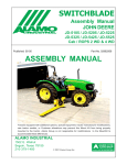
SWITCH BLADE
5 ft. & 6 ft. Sickle Bar Mower
Published 02/05
P/N 02982612S
SERVICE MANUAL
An Operator's Manual was shipped with the equipment in the Manual Canister.
This Operator's Manual is an integral part of the safe operation of this machine
and must be maintained with the unit at all times. READ, UNDERSTAND, and
FOLLOW the Safety and Operation Instructions contained in this manual before
operating the equipment. If the Operator's Manual is not with the equipment,
contact your dealer or Alamo Industrial (830-379-1480) to obtain a Free copy before
operating the equipment.
ALAMO INDUSTRIAL
1502 E. Walnut
Seguin, Texas 78155
830-379-1480
© 2005 Alamo Group Inc.
TO THE OWNER/OPERATOR/DEALER
All implements with moving parts are potentially hazardous. There is no substitute for a cautious, safe-minded
operator who recognizes the potential hazards and follows reasonable safety practices. The manufacturer has
designed this implement to be used with all its safety equipment properly attached to minimize the chance of
accidents.
BEFORE YOU START!! Read the safety messages on the implement and shown in your manual.
Observe the rules of safety and common sense!
WARRANTY INFORMATION:
Read and understand the complete Warranty Statement found in this Manual. Fill out the Warranty Registration
Form in full and return it to within 30 Days. Make certain the Serial Number of the Machine is recorded on the
Warranty Card and on the Warranty Form that you retain.
INTRODUCTION
ABOUT THIS MANUAL:
The intent of this publications to provide the competent technician with the information necessary
to perform the CORRECT repairs to the Alamo Industrial Product. This will, in turn provide for complete
customer satisfaction
It is hoped that the information contained in this and other Manuals will provide enough detail to
eliminate the need for contact of the Alamo Industrial Technical Service Dept. However, it should be
understood that many instances may arrive wherein correspondence with the Manufacturer is necessary.
CONTACTING MANUFACTURER: (Please help us Help You! Before You Call! )
Alamo Industrial Service Staff Members are dedicated to helping you solve yours or your
customer’s service problem as quickly and efficiently as possible. Unfortunately, we receive entirely to
many calls with only a minimum amount of information. In some cases, the correspondent has never gone
out to look at the equipment and merely calls inquiring of the problems described to him by the operator
or customer.
PART NUMBERS: Part numbers listed in this manual are subject to change without notice as
designs are made to adapter to the tractor or for a design improvement. Before ordering parts ALWAYS
Measure old part to make certain that is the one you will need. This manual is designed to be used along
with the Parts and Operators Manual.
Most calls received by Alamo Industrial Service can be classified into approx. 6 general categories.
1.
Hydraulic or Mechanical Trouble Shooting.
2.
Request for Technical Information or Specifications.
3.
Mounting or Fitting Problem.
4.
Special Service Problem.
5.
Equipment Application Problems.
6.
Tractor Problem Inquiries.
HOW YOU CAN HELP:
Make sure the call is necessary! Most of the calls received may not be necessary if the Dealer
Service Technician would do the following.
1.
Check the Service Information at your Dealership provided by Alamo Industrial, This would
include, Service Bulletins, Information Bulletins, Parts Manuals, Operators Manuals or
Service Manuals, many of these are available via the Alamo Industrial Internet site (Alamo - Industrial.
Com). Attempt to diagnose or repair problem before calling.
2.
If a call to Alamo Industrial is needed, Certain Information should be available and ready
for the Alamo Industrial Service Staff. Such information as, Machine Model, Serial Number, Your Dealer
Name, Your Account Number and Any other information that will be useful. This information is vital for the
development of a prompt and correct solution to the problem. This will also help to develop a database
of problems and related solutions, which will expedite a solution to future problems of a similar nature.
3.
The technician may be asked to provide detailed information about the problem including
the results of any required trouble shooting techniques. If the information is not available, The technician
may be asked to get the information and call back. Most recommendations for repairs will be based on
the procedures listed in the Service Manual / Trouble Shooting Guide.
CONTACT ALAMO INDUSTRIAL:
Alamo Industrial, 1502 E. Walnut St. Seguin TX. 78155,
Technical Service Dept. PH: 830-379-1480
Switch Blade 5' & 6' (Service Manual) 02/05
© 2005 Alamo Group Inc.
Index -1
INDEX
Section
Page
Section 1 -Specifications........................................................................... 1-1 to 1-6
Do Not Do or Allow Items (Read First Thing).................. 1-2 to 1-3
Standard Specifications................................................... 1-4
Torque Wrench Use Specifications.................................1-5
Hose End Fitting Torque Specifications.......................... 1-6
Nut & Bolt Torque Chart ..................................................1-6
Section 2 - Mechanical / Electrical Repairs & Adjustments................... 2-1 to 2Introduction.......................................................................2-2
Motor - Pump Electrical Circuit........................................ 2-3 to 2-6
Cutter Bar Lead Adjustment............................................ 2-7
Cutter Bar Pitch Adjustment............................................ 2-7
Cutter Bar Alignment........................................................2-7
Cutter Bar Guard Adjustment.......................................... 2-7 to 2-8
Cutter Bar Wear Plates................................................... 2-8
Cutter Bar Clips............................................................... 2-9
Cutter Bar Replacement................................................. 2-10
Knife Repair..................................................................... 2-9
Knife Replacement.......................................................... 2-9 to 2-12
Knife Bar Replacement....................................................2-10
Outer Shoe Replacement................................................ 2-13
Inner Shoe Replacement................................................. 2-13 to 2-15
Rock Guard, Clip & Wear Plate Replacement................ 2-13
Carriage Arm Replacement............................................. 2-16
Knife Drive Repair / Replacement................................... 2-17 to 2-18
Section 3 - Cylinder & Two Spool Control Valve Repair........................3-1 to 3-13
Introduction.........................................................................
3-2
Hydraulic Diagram........................................................... 3-3 to 3-4
Two Spool Control Valve..................................................3-5 to 3-6
Remote Control Cable (Cab Tractors)............................ 3-7 to 3-9
Cylinder, Bar Tilt Cyl. P/N 0693500A............................... 3-10 to 3-11
Cylinder, Curb Lift Cyl. P/N 0693400A............................. 3-12 to 3-13
Section 4 - Motor Repairs........................................................................4-1 to 4-14
Introduction.......................................................................4-2
Cylinder, Motor & Pump Hydraulic Circuit ...................... 4-3
Hydraulic Diagram........................................................... 4-4 to 4-5
Motor Dis-Assembly........................................................ 4-6 to 4-10
Motor Re-Assembly......................................................... 4-11 to 4-14
Motor Solenoid Control Valve Assembly......................... 6-7
Switch Blade 5' & 6' (Service Manual) 02/05
© 2005 Alamo Group Inc.
Index -2
INDEX
Section
Page
Section 5 - Pump Repair...................................................................................... 5-1 to 5-12
Introduction................................................................................................... 5-2
Hydraulic Diagram........................................................................................ 5-3 to 5-4
Pump Identification....................................................................................... 5-5
Pump Schematic..........................................................................................5-6
Pump Dis-Assembly.................................................................................... 5-7 to 5-8
Pump Re-Assembly..................................................................................... 5-9 to 5-12
Section 6 - Hydraulic Tank & Return Filter.................................................. 6-1 to 6-7
Introduction................................................................................................... 6-2
Hydraulic Diagram........................................................................................ 6-3 to 6-4
Hydraulic Tank Schematic........................................................................... 6-5
Hydraulic Tank Repair.................................................................................. 6-6
Oil Level / Temperature Sight Gauge........................................................... 6-6
Suction Strainer............................................................................................ 6-6
Tank Access Cover & Gasket...................................................................... 6-7
Motor Control Valve Soilenoid Assembly......................................................6-7
Switch Blade 5' & 6' (Service Manual) 02/05
© 2005 Alamo Group Inc.
Index -3
NOTES
Switch Blade 5' & 6' (Service Manual) 02/05
© 2005 Alamo Group Inc.
Index -4
Section 1
Model
Specifications
STATEMENT OF POLICY
It is the policy of Alamo Group to improve its products where it is possible and practical to do so.
Alamo Group reserves the right to make changes or improvements in design and construction at any
time without incurring the obligation to make these changes on previously manufactured units.
Switch Blade 5' & 6' (Service Manual) 02/05
© 2005 Alamo Group Inc.
Section 1 - 1
SPECIFICATIONS - SWITCH BLADE
This manual was carefully prepared by Alamo Industrial in an effort to aid the repair technisian
in keeping the performance of this mower up to the high standards for which it was designed. Its
purpose is to cover safety and to give recommendations for the proper repar, care and operation of the
mower. The repair person will want to be totally familiar with this manual so that they will be better
able to handle day to day service adjustments, maintenance and any necessary repairs.
For the purposes of product improvement, Alamo Industrial Company reserves the right to
make changes in design, material or specifications without notice and without liability therefore.
READ THIS BEFORE BEGINNING
ASSEMBLY, REPAIRS OR TESTING:
The Switch Blade: The Switch Blade has an independent hydraulic system
to operate the motor and the cylinder system. This system uses a tandem
pump for hydraulic supply and its own independent oil reservoir. Use caution
not to contaminate this system.
DO NOT
1.
2.
3.
4.
5.
6.
7.
8.
9.
10.
DO NOT short any wires across or allow them to be shorted out.
DO NOT attempt to jump across any wires or supply them with alternate power source.
DO NOT install higher rated fuses than are recommended by manufacturer.
DO NOT attempt to repair or adjust a component that is not intended to be repaired, example
sealed components as there are no serviceable components inside.
DO NOT let anyone attempt any testing or repairs unless they are an experienced and
qualified technician. Technicians must have proper tools, gauges, meters etc. to perform proper
diagnosis and/or repairs.
DO NOT perform any repairs with dirty tools or in dirty area. When working on hydraulic
components keeping system clean and free of contamination is important.
DO NOT start or engage system if the oil level is not at the proper level or condition. Never
start or run unit low or out of oil. If installing new pumpnever start engine unless pump & system
has been filled with oil, starting a pump dry will damage it.
DO NOT install / add any oil unless you know it is the correct type and the container is clean.
Make certain the oil is not contaminated with dirt or any liquid.
DO NOT Make repairs if it is going to be unsafe for you or the people around you, it is the
repair persons responsibility to secure the tractor and the surrounding work area. Tractor
should be disabled in a way that it cannot be started until the repair technician is ready to do so.
DO NOT use teflon tape or other pipe joint tape on fittings or hose connections. For pipe
threads, use a pipe thread sealant compound suitable for hydraulic service on OD thread.
Switch Blade 5' & 6' (Service Manual) 02/05
© 2005 Alamo Group Inc.
Section 1 - 2
SPECIFICATIONS - SWITCH BLADE
The OCCUPATIONAL SAFETY AND HEALTH ACT (1929.51 Subpart C) makes these minimum
safety requirements of tractor owners and operators:
Required of the Owner:
1.
2.
3.
4.
Provide a Roll-Over-Protective Structure that meets the requirements of this Standard;
Provide Seat belts that meet the requirements of this paragraph of this Standard SAE J4C;
Ensure that each employee uses such Seat belt while the tractor is moving;
Ensure that each employee tightens the Seat belt sufficiently to confine the employee to
the protected area provided by the ROPS.
Required of the Operator:
1.
2.
3.
4.
5.
6.
7.
8.
9.
Securely fasten seat belt if the tractor has a ROPS.
Where possible, avoid operating the tractor near ditches, embankments, and holes.
Reduce speed when turning, crossing slopes, and on rough, slick, or muddy surfaces.
Stay off slopes too steep for safe operation.
Watch where you are going - especially at row ends, on roads, and around trees.
Do not permit others to ride.
Operate the tractor smoothly - no jerky turns, starts, or stops.
Hitch only to the drawbar and hitch points recommended by the tractor manufacturer.
When the tractor is stopped, set brakes securely and use park lock, if available.
Safety Recommendations!
It is the business philosophy of Alamo Industrial Company to manufacture safe products for
use by our customers. In the interest of your safety, we are bringing to your attention practices that
can avoid serious injury. It is our belief that trained operators can avoid painful experiences by
carefully reading and adhering to the following recommendations. As a repair technician do not
modify this product in any way that will make this unsafe for the operator or anyone else around it.
WORK SAFELY. Most of the repairs can be performed by one man, but some of the parts
are very heavy. GET HELP IF YOU NEED IT. Use the right tools for the job. A floor jack or hoist will
be a big help, but make sure they are in safe condition. Keep the floor free from oil and grease
so you don't slip. WEAR SAFETY GLASSES, SAFETY SHOES AND GLOVES and make sure your
helper does too.
This machine can be dangerous if not operated safely. Do not operate it until you have read and
understand all safety and operation recommendations in Operators, Assembly, Service manuals.
DANGER
Know the equipment, learn to operate it correctly in a safe, level, open secure area before
trying to operate this unit in tight places or around other objects or people.
When stopping, shut off the mower, disengage PTO, Engage Tractor Parking brake. Shut off
tractor engine and be certain all rotating or moving mechanisms have stopped before attempting to get
near mower. Make certain that tractor is secured in a way that it can only be started if you are ready
for it to. This could include remove key and put it in a secure place. Disconnect battery cable which
should be done before any repairs or service is started.
Switch Blade 5' & 6' (Service Manual) 02/05
© 2005 Alamo Group Inc.
Section 1 - 3
SPECIFICATIONS - SWITCH BLADE
Standard Specifications: Switch Blade 5 ft. & 6 ft.
Break-A-Way Control............................................. Break-A-Way Pressure Contol Valve Block
Break-A-Way Relief................................................ 1500 psi Relief
Break-A-Way........................................................... Hydraulic Rotary Actuator, Self Returning
Cutting Size............................................................. Up to 1/2" in Dia. Material
Cutting Width...........................................................5 ft. or 6 ft. Option
Drive System...........................................................Hydraulic Motor
Hydraulic Cylinder Control.......................................Two Spool Control Valve
Hydraulic System.................................................... Self Contained
Hydraulic Tank.........................................................Steel Manufactured Type w/ Built in Mount
Hydraulic Filter.........................................................Standard, Tank Mounted
Hydraulic Oil Return Pressure Gauge.....................Standard, Tank Mounted
Hydraulic Hoses...................................................... High Pressure Standard
Hydraulic Hose Length............................................ Varies with the Tractor Model
Knife Drive............................................................... Planetary Drive Assembly
Knife Rock Guards.................................................. 3" Heavy Duty Industrial Bolt On
Knife Speed Control..........................………........... Pre-Set Governor
Knife Type................................................................Serrated Edge Standard
Lift & Fold.................................................................Hydraulic Cylinders Standard.
Motor Control........................................................... Electric over Hydraulic
Motor Control........................................................... Electric “ON” or “OFF” Selection
Motor Function.........................................................Electric Reversible Drive Direction
Mount Type.............................................................. Side Mount to Tractor Standard
Mounting to Tractor..................................................Factory or Field Mount Option
Operators & Parts Manual.......................................Standard, Extra Copies Optional
Paint.........................................................................Yellow Standard, Special Colors Optional
Pump Guard............................................................ Optional
Pump Mounting........................................................Tractor Engine Driven
Pump Size...............................................................2 Size Option (CID)
Pump Type.............................................................. Tandem Gear Pump
Pump Pressure..........Motor Circuit........................ 1750 psi @ 9 to 10 gpm
Cylinder Circuit................... 3000 psi @ 3.5 to 4.5 gpm
Skid Shoe Replacement..........................................Bolt on
Skid Shoe Size........................................................ Standard 3/16" Abraision Resistant Alloy
Skid Shoe................................................................ Standard w/ AG Shoe & Swathboard Option
Transport Locks...................................................... Standard, Manual Lock
Transport................................................................. Hydraulic Lifting and Folding
Switch Blade 5' & 6' (Service Manual) 02/05
© 2005 Alamo Group Inc.
Section 1 - 4
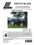
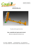
USING AN ADAPTER WITH A TORQUE WRENCH
Figure 1
If an adapter is attached to the drive of a torque wrench, the wrench will not give actual torque
indicated by the setting of the handle. A simple formula however, allows you to figure out what the
setting should be to deliver a predetermined amount of torque at the end of any adapter to the
fastener.
The following letters are defined as:
A
B
C
D
=
=
=
=
Length of the torque wrench when set at the middle scale setting (inches).
Length of adapter (inches from center hex bolt to center of torque wrench square shaft.
Desired torque at end of extrusion
Setting for accuracy within + or - 6%.
Here is a typical problem. You have an adapter that adds 10.0 inches to a torque wrench
length (dimension B) What should the setting be to obtain 320 ft. lbs. of torque at the end of the
adapter.
A
B
C
D
=
=
=
=
C
=
22.57 inches (length from adapter mounting point torque wrench to center of grip / handle)
10.0 inches (Length from adapter mounting point of torque wrench to center of hex slot).
320 ft. lbs. torque (desired torque at end of extension).
Unknown (setting you need to set torque wrench to = 320 ft. lbs for accuracy).
(A)
(22.57)
(22.57)
------------------- or 320 ----------------------- = 320 ------------------ = 320 X 222 ft. lbs.
(A + B)
(22.57 + 10.0)
(32.57)
Your Answer (D) is a setting of 222 ft. lbs. on the torque wrench will give 320 ft. lbs. of torque at the
bolt. By using the above formula an accuracy of + or - 6 % of the desired torque will result at the end
of the adapter due to length change during grip adjustment.
Switch Blade 5' & 6' (Service Manual) 02/05
© 2005 Alamo Group Inc.
Section 1 - 5
SPECIFICATIONS - SWITCH BLADE
HOSE END FITTING TORQUE SPECS:
Hose End Type: 37 Degree Angle End Steel Hose End Fittings*
Dash
Nominal Cyl.
Torque
Torque
Size
Size (in.)
in. lbs.
ft .lbs.
-4
1/4"
140
12
-6
3/8"
230
19
-8
1/2"
450
38
-10
5/8"
650
54
-12
3/4"
900
75
-16
1"
1200
100
-20
1-1/4"
1600
133
-24
1-1/2"
2000
167
-32
2"
2800
233
* Straight Threads do not always seal better when higher torques are used. Too much torque
causes distortion and may lead to leakage. DO NOT over torque fittings and DO NOT allow any
contaminants to enter system through fittings when installing them.
TORQUE VALUES - BOLTS:
Recommended Torque, Ft. lbs. & (Nm)
IMPORTANT! Listed below IS BOLT TORQUE and NOT APPLICATION TORQUE, Component
Application Torque will vary depending on what is bolted down and the type material (Metal) that is being
bolted together. Thread condition and lubrication will vary Torque settings.
Inche Sizes
Bolt
Dia.
inch
1/4
5/16
3/8
7/16
1/2
9/16
5/8
3/4
7/8
1
1-1/8
1-1/4
2 (B)
5 (D)
Metric Sizes
8 (F)
Plain Head 3 Dashes 6 Dashes
Not Used
Not Used
Not Used
35 (47)
55 (75)
75 (102)
105 (142)
185 (251)
160 (217)
250 (339)
330 (447)
480 (651)
10 (14)
20 (27)
35 (47)
55 (75)
85 (115)
130 (176)
170 (230)
300 (407)
445 (603)
670 (908)
910 (1234)
1250 (1695)
14 (19)
30 (41)
50 (68)
80 (108)
120 (163)
175 (230)
240 (325)
425 (576)
685 (929)
1030 (1396)
1460 (1979)
2060 (2793)
ALWAYS
CHECK
MARKINGS
ON
TOP
OF
BOLT
HEAD
OR
OTHER
BOLT
DESCRIPTIONS
Switch Blade 5' & 6' (Service Manual) 02/05
© 2005 Alamo Group Inc.
Section 1 - 6
Bolt
Dia.
mm
6
8
10
12
14
16
18
20
22
24
27
30
33
36
4.8
5
11
20
37
60
92
118
160
215
285
450
600
800
900
8.8
7
20
40
70
100
155
216
270
330
500
875
1200
1600
2100
10.8
12
25
58
105
140
200
280
355
430
700
1000
1700
2300
3000
Section 2
Mechanical Repairs
& Adjustments
RH & LH Models
IMPORTANT NOTE:
The RH Single Wing and the LH Dual Wing adjust and repair procedures are
the same with the exception it will be a mirror image and mounted on the opposite
side. Make note which you are working on, the illustrations in this manual are
showing mostly the RH Wing.
Switch Blade 5' & 6' (Service Manual) 02/05
© 2005 Alamo Group Inc.
Section 2 - 1
INTRODUCTION TO REPAIRS
INTRODUCTION:
In Most diagrams there are no Component Part Numbers Listed, Only Item
numbers and Descriptions, This is because most parts shown as breakdown in drawings are for location
& identification only and if available as replacement parts will be listed in the Parts/Operators Manual. NO
Dirt at all should be around Parts during repairs.
BEFORE STARTING REPAIRS: Service Rules (READ THIS)
1.
2.
3.
4.
5.
6.
7.
8.
9.
Remove Front Cover. Clean Pump and surrounding area completely before removing any connec
tions or Lines. NO DIRT OR DEBRIS CAN BE ALLOWED ON OR NEAR HYDRAULIC SYSTEM IF
IT IS BEING WORKED ON, ANY DIRT OR CONTAMINANTS IN SYSTEM NO MATTER HOW
SMALL WILL DAMAGE SYSTEM!
After cleaning around all connections thoroughly, Disconnect all connections, Lines, Hoses, Wiring
and Remove the Pump Completely from the Tractor. Plug all hoses and Lines on Tractor and on
Pump, DO NOT leave any open Lines. NO Contamination Should be allowed into system at all.
Clean Area, Clean all Tools, Pans etc. The cleaning of Area and Tools MUST be done before moving
(Cleaned) Pump there. Drain Oil from Pump, Recheck outside of Pump to Make Sure it is Clean
After disassembly of Pump wash all metal components in clean solvent.
Use compressed Air to dry parts after washing (Compressed air must be filtered and moisture free).
DO NOT wipe them dry with Paper Towels or Cloth as these will leave lint and/or dust contamination.
DO NOT USE Compressed Air to spin any component (Such as Bearings or Plates) as this will
damage them and could be dangerous.
Always use new Seals when reassembling Hydraulic Pumps, Lubricate the new rubber Seals with
a Petroleum Jelly, (Vaseline) before installing them.
DON'T reinstall worn/damaged Parts in Pump, DO NOT Use a worn/damaged Pump Housing.
Torque all Bolts over Gasketed Joints. Then repeat the Torque sequence to make sure Bolts are tight,
some times Gaskets can give a Torque reading that is OK but is not, so always recheck Torque.
Verifying the accuracy of Pump Repairs on an authorized test stand is essential.
RECOMMENDED TOOLS:
1.
2.
Hex Allen Wrench (Qty 5) (9/16", 5/32", 5/16", 3/32", 5/64"
Retaining Ring Pliers (Qty 3), 1 each of Internal (Straight .070 tip) internal (Straight .090 tip) & 1 each
External (Straight 0.90 tip)
3. Retaining E-Ring Applicator (Qty 2), 1 each 9/32" & 1 each 1/2".
4. O-Ring Pick (Qty 1)
5. End Wrench (Qty 4), 1 each of 7/16", 9/16", 3/4", 1"
6. Torque Wrench (Qty 1), 0 to 100 ft. lbs. (135.6 nm) capacity
7. Hammer, Soft Face (Qty 1)
8. Seal Driver Set (Qty 1)
9. Arbor Press (Qty 1)
10. Sockets (Qty 3) 7/16", 9/16", 3/4" , Drive Size should match Torque Wrench Drive)
11. Light Petroleum Jelly (Vaseline)
12. Locktite, # 222 and #277 or equivalent (Qty 1 tube each)
RECOMMENDED GAUGES FOR DIAGNOSTICS:
1.
2.
3.
Inlet Vacuum: 30 PSI to 30 in Mercury (207 bar to 0 bar)
System Pressure Gauge: 6,000 PSI (700 bar)
Charge Pressure Gauge: 0 to 500 PSI (0 to 25 bar)
Switch Blade 5' & 6' (Service Manual) 02/05
© 2005 Alamo Group Inc.
Section 2 - 2
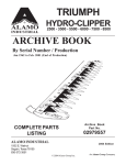
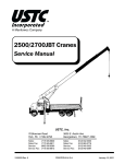
MOTOR - PUMP ELECTRICAL CIRCUIT
Electrical Circuit: RH Wing Mower
The electrical circuit is a pre-assembled wire harness that will control the motor functions. The
harness will be used with a push pull off/on switch that prevents the tractor from being started when motor
is engaged. The wire harness uses a three position toggle switch that is used to reverse the knife bar
direction of travel. These switch are not part of the wire harness assembly, These switches must be
connected correctly to operate correctly (See Figure 2). There is a motor control valve mounted on top
of the hydraulic tank that will have two electrical solenoids connected to it. The wire harness has two plugs
on one end that connects to the solenoids, one plug will have longer wire (also has White Wire) than the
other and will connect to the solenoid further most from the cutter bar mount. The other plug with the
shorter wire (has Yellow Wire) will connect to the first solenoid closet to the operator. The Starter solenoid
wires and the 12 V power supply wire will have to be connected to tractor wiring, The power source wire
must be connected to a power source that is only charged when the tractors key switch is in the on
position. If power supply wire is connected direct to a power source it will run the tractor battery down.
When connecting wire harness to toggle switch the red wire MUST connect to the center post
of switch, the yellow and the white wire must connect to the two outside post, it will not mater which
outside post as long as one each of yellow or white wire is connect to the outer post (See Figure 2).
White #16 Wire
(Spade Connector)
123456
123456
123456
123456
- Black #16 Wire
3
1
Use Gaskets to
Seal Both Plugs
Red #16 Wire
(Spade Connector)
- Black #16 Wire
(Common Ground)
2
Yellow #16 Wire
(Spade Connector)
Front Solenoid Plug
White #16
Wire
Brown # 12 Butt Connectors
Wire to Starter Solenoid
Yellow #16 Wire
Brown #12 Wire
Rear Solenoid Plug
Red #16 Wire
1
+ Red #16 Wire
(12 Volt Supply)
3
2
- Black #16 Wire
NOTE: + Red # 16 Wire (12 Volt Supply) Connect to Key Switch Connection
that is positive only when ignition key is in “ON” Position. If connected to
direct power supply and push pull switch is left on when tractor is stopped and
parked it will run down the tractor battery.
Push Pull Switch, Wire Harness plug will only fit one way on push
pull switch to prevent it being connected wrong.
Figure 2
4 Terminal Plug
for Push Pull Switch
This Wire Harnes Used for RH Wing
Switch Blade 5' & 6' (Service Manual) 02/05
© 2005 Alamo Group Inc.
Fuse Holder with 10
AMP Inline Fuse
Section 2 - 3
MOTOR - PUMP ELECTRICAL CIRCUIT
Electrical Circuit: Dual LH Wing Mower
The electrical circuit for LH Wing is a pre-assembled harness that controls the motor & cylinder
functions. The harness is used with a off/on switch that allows RH mower or LH mower to be run as
decided by the operator but not both at same time. The wire harness for the LH mower will be used with
the wire harness for the RH mower. The wire harness is connected to Diverter Valves that are connected
into the hydraulic lines to select the oil flow from one mower or the other. The solenoid valve on the tank
will still be used to reverse the flow of oil changing rotation direction on cutter bar. The wire harness has
two plugs on one end that connects to the Selector Valves. The Plugs on the harness will connect to the
diverter valve solenoids, both these solenoids will be open at the same time or closed at the same time.
If the cutter bar on one mower runs and the cylinder on the other side operate the hoses are not connected
correctly (See Hydraulic Diagram for Dual LH Wing). The12V power supply wire will have to be connected
to tractor wiring, The power source wire must be connected to a power source that is only charged when
the tractors key switch is in the on position. If power supply wire is connected direct to a power source
it will run the tractor battery down when parked if the switch are left on as the solenoid could be activated
(See Figure 2A)
When mounting the two position toggle switch you will need to drill a 1/2" hole in the valve mount
on the RH side of it near the bottom (See Figure 2C). Install the toggle switch with the "On" position up.
There is a decal that mounts on valve mount that will explain the operation of the RH or LH selector toggle
switch.
The wire harness for the LH diverter valves will only have two wires connected to the plug, these
two wires are #16 GA Red (+) and # 16 GA black (-). These wire are connected together in the two plugs
(The red & red and the black & black), with the fuse removed to prevent current flow the plugs can be
checked with an Ohm Meter from plug to plug and plug (Red Wires) to toggle switch. The black wires are
connected to a common ground and can be tested to a ground source (See Figure 2B).
Reference, Valve mount will vary with tractor model
16 ga. Red Wires
Decal
Toggle Switch
NOTE: Connect Black Ground Wire & Red Supply
wires to same connection as RH Wing Wire Harness
location. Item 3 Toggle switch needs to be installed
with on position up. 1/2” Hole for Item three will need to
be drilled (See Parts Manual for Part Numbers).
Toggle Switch Boot
Black Ground Wire
Diverter Valve
f/ Cyl Control
Wire Harness, LH Wing
Red 12V Supply
wire w/ inline Fuse
Figure 2A
Diverter Valve f/
Motor Control
Switch Blade 5' & 6' (Service Manual) 02/05
© 2005 Alamo Group Inc.
Section 2 - 4
MOTOR - PUMP ELECTRICAL CIRCUIT
Electrical Circuit: Dual LH Wing Mower (Continued)
IMPORTANT: All Toggle Switches and push pull switches must be installed before the two spool
control valve is mounted as once the valve and hoses are installed they are difficult to get to. If switches
must be repaired or removed, the removeal of the control valve may be required. The hose should not
require disconnecting only the valve. Lay the valve with hoses to one side to get to the switches.
The componets used when a dual LH Wing is installed will not replace the components used in
the mounting of the RH Wing, they will be used with the RH components. The stand for the valve mount
and the valve mount can vary with the type/ model tractors be used. Shown here is a stand and mount
typical of what is used onROPS tractor without cab (See Figure 2D). If mounting on cab tractor the
controls will be worked through remote cables and this type mount will not be used. The Toggle switches
and push pull switch will be mount onto brackets witch connect to control cable stand / mount, the toggle
switch connections will be the same for wiring. Onlt the mounting of the switch itself will be different.
Red #16 Wire
(12 Volt Supply)
3
1
Use Gaskets to
Seal Both Plugs
2
NOTE: + Red # 16 Wire (12 Volt Supply) Connect to Key Switch Connection
that is positive only when ignition key is in “ON” Position. If connected to
direct power supply and switch is left on when tractor is stopped and parked it
will run down the tractor battery.
It will not matter which plug goes on which diverter valve as both
diverter valves are activated at the same time with the same toggle switch.
To Diverter Valve
Solenoid Plug
Black #16
Wire (Ground)
Fuse Holder with 10
AMP Inline Fuse
Red #16 Wire
(12 Volt Supply)
1
+ Red #16 Wire
4” Long
(12 Volt Supply)
Two Position Toggle
- Black #16 Wire
Switch “OFF” &
16” Long
“ON” Only
(Common Ground)
Red #16 Wire
(2” Long) F/ 12
Volt Supply
"ON"
1234
1234
1234
3
2
Red #16 Wire
(2” Long) F/
Plug Connectors
To Diverter Valve
Solenoid Plug
Black #16 Wire
(Ground)
This Wire Harnes Used for LH Wing
Figure 2B
Figure 2C
Valve Mount
Drill one hole 1/2" dia.
f/ LH Toggle Switch
9/16" to Center Hole
Figure 2D
Switch Blade 5' & 6' (Service Manual) 02/05
© 2005 Alamo Group Inc.
Section 2 - 5
"OFF"
MOTOR - PUMP ELECTRICAL CIRCUIT
Motor & Cylinder Diverter Valve
Solenoids: Used w/Dual LH Wing
Solenoid Coil
Cylinder Diverter
This Only applies if unit has a LH dual Wing, RH
Valve (#4 Ports)
Wing Only models DO NOT use diverter valves. The
diverter valve is a solenoid operated electrical activated directional valve. It is designed to send the oil
flow to one wing or the other, NOT to both at the same
Solenoid Coil
time. The flow of oil pressure to the motor and
cylinders is controled by the operator, he can run one
Motor Diverter
wing at a time. The Solenoids can be removed and /
Valve
(#8 Ports)
or changed without removing the diverter valve or the
valve connections. There is a nut on the end of the
solenoid that when removed will allow the coil and
tube assembly to be removed. The solenoid can be
Figure 2E
replaced as an assembly or by parts. The wire
harness plugs will have to be disconnected from the coils. There are no adjustments to the solenoid or
valve ( See Figure 98).
To test the solenoid this can be done with a test light or a volt meter. Test the wire harness first to
make sure that the connections are good and there is current present. REMEMBER the solenoids are
connected to the toggle switch which means both diverter valve solenoid are energized at once, and this
is determined by the toggle switch. If you check one solenoid and it has current then check the other
solenoid at the plug.
The coil can be tested by using a small paper clip. Remove the solenoid coil retaining nut. Energize
the coil and stick the small paper clip to the end of the stem sticking out of the coil. The paper clip should
stick to the stem magnetically and fall off when the coil power is shut off. Note: use a small paper clip or
small wire as the magnetic pull of coil is very low and will not carry a heavy weight. The coil is working
properly if it held the paper clip.
If all the test show to be OK, check the stem that screws into the valve body, The best way to check
this is to try a different one, the other one on the other side of valve can be switched or a new one can
be tried. When removing the stem inspect it when you get it out to see if there is something stuck in it.
Figure 2F
Switch Blade 5' & 6' (Service Manual) 02/05
© 2005 Alamo Group Inc.
Section 2 - 6
CUTTER BAR ADJUSTMENTS
Lead Adjustment:
The lead angle is how far the outer end of
the cutter bar runs forward of the inner end.
The lead angle of the cutter bar is preset at
the factory at 3/6" per foot. The lead may be
changed if desired. To reduce the lead, move the
washers from the outside of the cutterbar support
plate in between the rubber strike pad and plate
(See Figure 3).
Pitch Adjustment:
The Pitch angle is the level of the cutter bar
front to rear or what angle the blade is to level front
to rear. Different cutting conditions allow you to
change the pitch of the knife by + 15° to - 15° or
level.
The pitch is set by loosening the three
mounting bolts that connects the skid shoe /
Break-A--Way assembly to the carriage arm assembly (See Figure 4 & 4A). The two lower bolts
holes are slotted, this will allow the cutter bat to be
tipped up +15° or down -15° in front. Set Pitch at
what works best for your application.
Figure 3
Non-Slotted
Hole
Cutter Bar Alignment:
All cutting is done by the knife passing over
ledger plate in the guard. It is vital that these
sections are parallel with the plates and in contact
with them, (See Figure 5 & 6).
The knife should move smoothly in the
cutterbar guides and every knife section should
rest on the ledger plate to make a shear cut. This
means the guards, ledger plate, wear plates, clip
and knife head caps must be in good condition and
correctly set. If these parts become loose or worn,
the knife will flop around in the cutter bar, chewing
and tearing instead of cutting.
Figure 4
Guard Adjustment:
1.
To align the guards, the only method provided to accomplish this very important adjustment is to bend the guards into alignment with a
hammer. No easier method has been found to
adjust heavy duty guards which will stand up in
rocky conditions.
Continued Next Page
Figure 4A
Switch Blade 5' & 6' (Service Manual) 02/05
© 2005 Alamo Group Inc.
Section 2 - 7
Slotted Holes
CUTTER BAR ADJUSTMENTS
Note: Guards are cast from alloy steel. If they are
worked to much, they will harden and cannot be bent.
In this case remove the guard from the bar and
remove the ledger plate. Heat the guard to a cherry
red and cool. This process will anneal the guard
enough that it can be bent.
2.
Raise the bar to about 45°. Make certain the knife
is at the full retracted position of the stroke so the flywheel
doesn't suddenly turn and catch your fingers in the knife.
A pair of Vise Grip Pliers gripped tightly to the knife on the
upper side of the rock guard will allow extra protection
against cutter bar from turning. Make certain the Tractor
is secured so it cannot be started until you are the one
Figure 5
who decides to start it when the job is finished, all tools
removed and cleaned up and it is safe to do so. Make
certain tractor parking brake is set.
3.
Sight down the bar and look for a knife section in
close contact with a guard ledger. If the section to the right
and left are both 1/8" of the ledger do not bend the two
sides up until they contact the knife. This is wrong (see
Figure 5), the high guard should be knocked down until all
three contact. The higher up a guard gets bent, the more
the knife section will tend to contact only the tip (See
Figure 5 & 6).
4.
Bolt the guards tight and strike them in the thick
part, just in front of the ledger plates (see Figure 6). Do not
pound down the guard lips as the knife might bind.
Retighten the bolts as each guard is aligned. Disregard
Figure 6
the position of the guard points. It is the ledger plate which
must be kept in line. Blunt points should be filed sharp.
5.
Start from the inner shoe, adjust each guard so that the knife section and ledger are parallel and
reasonably close to each other. Find the high guard and knock them down. Usually, the only time it is
necessary to knock a guard up is when new guards are first installed on the bar.
6.
Make certain that the first knife section is contacting the inner shoe ledger plate. If it doesn't
contact, check the first or second guard which may be holding the knife up or the inner shoe ledger plate
may be worn out.
7.
Finally, align the industrial outer shoe in the same way as the guards. (See Figure 5 & 6 and step
1 through 6)
Wear Plates::
The wear plates must line up with each other to give the knife back straight bearing along its entire
length. Wear plates should project approximately 1/16" in front of the leading edge of the cutterbar after
adjustment. Alamo Industrial wear plates are hardened on both edges. After the first edge has worn back,
simply turn over the plate to obtain a new wearing surface.
Switch Blade 5' & 6' (Service Manual) 02/05
© 2005 Alamo Group Inc.
Section 2 - 8
CUTTER BAR ADJUSTMENTS
Clips:
After all guards are adjusted, it is necessary
to see that the knife clips are bent down to within 1/
64" of the section. The easiest way to check this is
to hold the knife down on the ledger plate and use a
feeler gauge or the cover of a paper match book to
measure the clearance. Do not attempt to hold the
tightly against the ledger plate with the clips. Knock
the clips down with a hammer. A light blow with
hammer is all that is required. If the clips drag on the
knife, pry them up. Drag will bind the knife and wear
the clip very rapidly (See Figure 7 & 8).
Clips
Knife Repair:
ALWAYS USE A SHARP KNIFE. A dull knife
cuts poorly, may plug and doesn't do a clean job.
Keep the knife straight with the sections firmly
riveted to the knife back. When sharpening knife, be
careful to restore the original shear angle and bevel
of 23 °. Properly and improperly ground knife sections are shown (See Figure 9). A knife section that
has been ground several times may have the proper
angle and bevel and still be unserviceable because
the hard cutting edge has been ground away and the
section is to short to cut everything encountered.
Figure 7
Match Book Cover
Knife Replacement:
Replace worn or broken knife sections.
Alamo Industrial knife sections are heavy duty sections made of special steel and will stay sharp for
many more hours than conventional sections.
New Sections proper bevel and
angle for good work.
Improperly ground sections - narrow bevel
and wrong angle which
changes the angle of
shear.
Figure 8
properly ground sections even after repeated griding, proper
bevel and angle are
retained.
Figure 9
Switch Blade 5' & 6' (Service Manual) 02/05
© 2005 Alamo Group Inc.
Section 2 - 9
Clips
Sections ground off
center, destroying the
register of blade in
guard.
CUTTER BAR REPLACEMENT
Cutter Bar Assembly Replacement:
Replacement of the complete cutter bar assembly will require the cutter bar assembly to be
unbolted from skid shoe / break-a-way assembly. Wear gloves as the knives on the cutter bar can be
very sharp and can cut you. (See Figure 10)
It will not be require to remove any of the hydraulic hoses or even take them loose. Looking down
at the planetary drive (and Hydraulic Motor Assembly) there are four nuts in the plate that is attached to
the drive assembly. Remove these four nuts, if you want to remove the four carriage bolts the skid shoe
will have to be unbolted and removed. When lifting the drive assembly up and away from the cutter bar
take notice of the four tube spacers under the drive assembly, there are two different length of the
spacers. The short ones go to the rear and the long ones go to the front. Once the drive assembly has
been lifted off you will see a nylon bearing in the knife bar head clamp, it should have stayed in the clamp.
There will be two more bolts connecting cutter bar to break-a-way assembly once these nuts
are removed the cutter bar should lift up over the bolts if they were left in. There will be a square plate
under the cutter bar that has 4 holes in it, make certain to note this for reassembly
When reinstalling cutter bar reverse the disassembly procedures. Make certain the nylon
bearing is in good condition or replaced, sometimes the clamp will have to be loosened to get the nylon
bushing installed into clamp and the drive stud that is attached to the drive assembly with two socket
head bolts, DO NOT tighten clamp bolt now. This drive stud can be unbolted from drive assembly,
inserted into nylon bearing and re-bolted to drive assembly later.
The nuts on the carriage bolts (4 short and 2 long 3/4" carriage bolts) that retain the drive
assembly and the cutter bar to the break-a-way assembly must be torqued to 85 ft. lbs.
After the assembly is finished the guards, clips and ledger must be checked, see the previous
section in this manual for setting cutter bar components.
Tighten the clamp bolt around the drive stud, use a good thread lock compound on clamp bolt
and tighten the clamp bolt until the up & and down movement of clamp on drive stud is removed. DO
OVER TIGHTEN the clamp bolt as the drive stud has a bearing inside that will be damaged.
Short Tube
Spacers
Knife Drive Stud Assembly
Motor
Planetary Drive
Assembly
Nylon Bearing
Clamp & Clamp Bolt
Long Tube
Spacers
Knife Head Weldment
Knife Drive Stud Assembly
Blade Sections
Knife Backing Strip
Figure 10
Switch Blade 5' & 6' (Service Manual) 02/05
© 2005 Alamo Group Inc.
Section 2 - 10
KNIFE BAR REPLACEMENT
Knife Bar Replacement:
Replace the Knife Bar assembly will require the cutter bar assembly to be unbolted from skid
shoe / break-a-way assembly. Wear gloves as the knives on the cutter bar can be very sharp and can
cut you. (See Figure 10 & 11)
It will not be require to remove any of the hydraulic hoses or even take them loose. Looking down
at the planetary drive (and Hydraulic Pump Assembly) there are four nuts in the plate that is attached
to the drive assembly. Remove these four nuts, if you want to remove the four carriage bolts the skid
shoe will have to unbolted and removed. When lifting the drive assembly up and away from the cutter
bar take notice of the four tube spacers under the drive assembly, there are two different length of the
spacers. The short ones go to the rear and the long ones go to the front. Once the drive assembly has
been lifted off you will see a nylon bearing in the knife bar head clamp, it should have stayed in the clamp.
There will be two more bolts connecting cutter bar to break-a-way assembly once these nuts
are removed the cutter bar should lift up over the bolts if they were left in. There will be a square plate
under the cutter bar that has 6 holes in it, make certain to note this for reassembly.
Use caution the knife bar can be very sharp, it is recommended that you wear gloves to protect
your hands. The Knife Bar will slide out at the drive end, if it will not slide out then something is wrong.
Check the rock guards, clips and other components to see where it is to tight. The easiest way if any
of these make it to tight is to unbolt them and remove them for now. The new or repaired knife bar will
install the same way, it will slide in from the drive end under clips and between rock guards. DO NOT
use hammer or force to install knife bar, if it will not slide in find out why because if the bar is forced in
it will be damaged or other component will be damages. The Knife bar and cutter bar can not operate
fitting tightly together they will bind causing damage..
When reinstalling cutter bar reverse the disassembly procedures. Make certain the nylon
bearing is in good condition or replaced, sometimes the clamp will have to be loosened to get the nylon
bushing installed into clamp and the drive stud that is attached to the drive assembly with two socket
head bolts, DO NOT tighten the clamp bolt at this time. This drive stud can be unbolted from drive
assembly, inserted into nylon bearing and re-bolted to drive assembly later (See Figure 10 & 11). if the
drive stud is removed from the drive assembly when you reinstall it the two socket head bolts will need
to be torqued to 35 ft. lbs.
The nuts on the carriage bolts (4 short and 2 long 3/4" carriage bolts) that retain the drive
assembly and the cutter bar to the break-aDrive Stud
way assembly must be torqued to 85 ft. lbs.
Nylon Bearing
Tighten the clamp bolt around the
drive stud, use a good thread lock comClamp & Clamp Bolt
pound on clamp bolt and tighten the clamp
bolt until the up & and down movement of
Knife Head Weldment
clamp on drive stud is removed. DO OVER
TIGHTEN the clamp bolt as the drive stud
has a bearing inside that will be damaged.
Blade Section
After the assembly is finished the
guards, clips and ledger must be checked
for clearance, see the previous section in
this manual for setting knife bar to cutter bar
Knife Backing Strip
components (See Figure 10 & 11).
The skid shoe will be the last item
reinstalled. Make certain the rod deflector
Figure 11
which bolts to the front of the skid shoe is
pointed correctly.
Switch Blade 5' & 6' (Service Manual) 02/05
© 2005 Alamo Group Inc.
Section 2 - 11
KNIFE REPLACEMENT
Knife Replacement:
The Knives are very sharp, use gloves and
caution when working with these knives. Secure
tractor so that it cannot be started until you are ready
for it to. Set the parking brake on the tractor. Make
certain cutter bar is completely on the down stroke,
this will prevent the cutter bar from moving down
ward. Also the Knives can be locked with a clamp so
it cannot move unless you want it to. If cutter bar
needs to move the best way is by using a punch in
one of the holes on the flywheel, remove clamp the
replace it after you have moved the cutterbar.
To remove the old knife the Knife retaining
bolt will have to be removed, usually these bolts
cannot be used again and it is recommended that
new one be used when changing knives. When lock
nut is removed the bolt should not fall out as the
shoulder of the bolted is ridged to make a drive in fit.
Drive the bolt out from the top, there are two bolts per
knife. There are two different length of these bolts,
the majority is 5/8" long. The first 7 bolts which also
bolt the knife section, knife backing strip and the knife
head weldment together is longer, 1-1/64" long.
Remove the locknut, if the lock nut cannot be removed these bolts can be cut with a chisel under the
lock nut and the bolt driven out from the top, use
caution and not drive a punch or anything through the
hole that is larger than the bolt as it will damage the
hole in the knife backing plate.
Replace a Knife or a group of knives. The
knife can be changed without disassembly of the
cutter bar. The Knife retaining bolt is a special ridged
shouldered bolt, this makes the bolt have a wedged
fit into the knife backing strip. The special bolt will
need to be driven into the knife backing strip from the
bottom until the head of bolt bottoms out on the knife
backing strip. Install the new cone locknut and
snugly secure the bolt, do not over tighten these
bolts as they are 1/4" gr. 5 and will twist off. Torque
9 to 10 ft. lbs max. If all the rock guards and clips
were adjusted right to begin with they should not
have changed, but check them for alignment to
make certain. If the rock guards and clips need to be
adjusted go back to the guard ajustment section
earlier in the manual. (See Figure 11, 12, 13 & 14)
Special Cone
Locknut
knife
Ridged
Shoulder
© 2004 Alamo Group Inc.
123
123
123
123
123
1234
1234
1234
1234
1234
Figure 12
Figure 13
Figure 14
MAVERICK (Service Manual) 12/04
Section 2 - 12
knife
knife
Ridged
Shoulder
123
123
123
123
123
123
123
123
123
Knife
Backing
Strip
Special
Knife Bolt
OUTER SHOE ASSEMBLY REPLACEMENT
Outer Shoe Assembly Replacement:
The outer shoe assembly bolts to the last two holes in the cutterbar. There are two different length
bolts used here because the last bolt will also mount the outer shoe sole to the outer shoe assembly.
These are 7/16" grade 5 carriage bolts and will torque
45 to 50 ft. lbs. The outer shoe sole is a replaceable
wear item and be replaced as needed without disassembly of the cutterbar (See Figure 15 & 16).
Cutter Bar
Inner Shoe Replacement:
The inner shoe bolts to the Break-a-way
assembly using two bolts in the rear and the rod
deflector in the front. There is also a motor cover
weldment that bolts over the motor and drive assembly that is bolted on with three bolts (See Figure 17 &
18).
Outer Shoe Asy
Outer Shoe Sole
Figure 15
Rock Guard, Clip & Wear Plate
Replacement:
The rock guards, clip and wearplates can be
replaced without removing that cutterbar or knife bar
assembly. They are bolt on items that can be bolted
one at a time for repair or they can all be replaced all
at the same time. Anytime the guards, clips or
wearplates are replaced they will have to be checked
to make certain they are fitting correctly. See the
guard, clip and wearplate adjustment section on
previous pages. The bolts mounting rock guards are
7/16" grade 5 plow bolts and will torque 45 to 50 ft. lbs
(See Figure 16)
Figure 16
Figure 17
Figure 18
Switch Blade 5' & 6' (Service Manual) 02/05
© 2005 Alamo Group Inc.
Section 2 - 13
INNER SHOE WELDMENT REPLACEMENT
Inner Shoe Weldment Replacement:
The Inner Shoe Weldment replacement will require other components to be removed in order
to replace the weldment. Removal or disconnection of hydraulic line will not be required. DO NOT Start
tractor after this repair has began, secure tractor from starting and set parking brake on tractor.
1.
Inner Skid Shoe Plate will have to be removed, See inner shoe replacement on previous page
(See Figure 17 & 18).
2.
Drive Assembly will need to be removed,
See cutter bar assembly replacement on previous
pages (See Figure 10).
3.
Cutter Bar Assembly will need to be removed,
See cutter bar assembly replacement (See Figure 10).
4.
The Rotor Actuator is a hydraulic operated
break-a-way unit. Before starting repair put a drain pan
under rotor actuator. The hoses at the actuator should
be loosen slowly, but NOT Removed to relieve
pressure in lines and actuator. Make certain that it is
the hose at the actuator and not the control or the relief
valve block. After the pressure if any has been relieved
the hoses can be retightened. This is important DO
NOT try to unbolt Actuator Pin or any other frame
Figure 19
component until the hoses have had the pressure
relieved. (See Figure 19, 20 & 21)
5.
The Skid Shoe weldment
can be removed with the Rotor
Motor
Actuator attached to skid shoe
weldment and then removed or
it can be left bolted to Back Pivot
Drive Assembly
Plate. The rotor actuator is not
part of the skid shoe weldment.
Long Tube Spacer
Short Tube Spacer
To remove the actuator from
Inner Skid Shoe
skid shoe remove the 8 bolts
Break-A-Way Rotor
Weldment
that retain break-a-way rotor acActuator Pin
tuator pin. The rotor Actuator
pin goes all the way through the
Motor Drive
shoe weldment and can be reAsy Cover
moved by pushing up on pin
from bottom (See Figure 19, 20
The Back Plate
& 21) 6.
is retained by 3 bolts which Back Pivot
mount it to the Carriage Arm, It is Plate
not required to remove the Back
Pivot Plate to remove skid show
weldment. It must removed, reRotor Actuator
move the three retaining bolts to
drop the back plate.
Inner Skid Shoe
Figure 20
Switch Blade 5' & 6' (Service Manual) 02/05
© 2005 Alamo Group Inc.
Section 2 - 14
INNER SHOE WELDMENT REPLACEMENT
6.
If the Back Plate has been removed from the carriage arm, it will have to be reset after the
reassembly is done. See the Pitch adjustment in previous instruction (See Figure 4). The adjustment
to the cutter bar should be check and reset if required after reassembly.
7.
Before beginning the reassembly read this section as well as the section that pertains to the
component listed below. This is important that these components be assembled correctly as well as
adjusted properly. The assembly of the skid shoe weldment, replacement of the Rotor Actuator, Drive
Assembly, Cutter Bar, Skid Shoe and Drive Assembly Cover will be reinstalled by reversing the
disassembly instructions. (See Figure 10 thru 21)
3/8" Bolts
Rubber Bumper
Pad
3/8" Lockwashers
Back Pivot
Plate
Rotor Actuator
Retaining Pin
Skit Shoe
Weldment
Rotor Actuator
Figure 21
Rotor Actuator
Mounting Bolts
Drive Stud Bearing Asy
Nylon Bearing
Clamp & Clamp Bolt
Knife Head Weldment
Blade Section
Knife Backing Strip
Figure 22
Figure 23
Switch Blade 5' & 6' (Service Manual) 02/05
© 2005 Alamo Group Inc.
Section 2 - 15
CARRIAGE ARM ASSEMBLY REPLACEMENT
Carriage Arm Assembly
ment:
Replace-
The carriage arm replacement will require
the Back Pivot Plate to be unbolted with the skid
shoe / break-a-way assembly to be removed with
Back Pivot but not disassembled. The skid shoe /
break-a-way assembly can be removed by unbolting the back pivot plate from the carriage arm (See
Figure 17 thru 25). The hydraulic hoses to the
motor will not have to be disconnected but the hose
brackets may have to be disconnected to allow the
assembly to be moved outward far enough to clear
carriage arm assembly. If the complete cutterbar /
break-a-way assembly needs to be moved it is
sometimes easier and cleaner to unbolt the motor
and the complete assembly can be removed an the
motor can be moved out of the way with the hoses
attached to it. DO NOT pull assembly with the
hoses attached and damage them.
To remove the carriage arm the lift and tilt
cylinder will need to be disconnected, the hoses will
not require disconnecting, the cylinders can be set
aside with the hoses connected. Remove the roll
pins from the carriage pin. The carriage arm is
pinned to the back pivot plate and the tractor mainframe. The mounting frame to attach to the tractor
will vary from tractor model, but the way the carriage arm is pinned to will not. Drive the carriage
pins out and carriage arm will lift out (See Figure 24,
25 & 26).
To reassemble the carriage arm reverse
the disassembly instruction, insert carriage arm,
insert carriage arm pins, install roll pin in to carriage
arm pin. Install the lift and tilt cylinders, make certain
hoses connecting to the cylinders is not twisted or
routed wrong as they could be damaged. Attach the
back pivot plate with the carriage pin. Bolt the
cutterbar / skid shoe assembly to the back pivot
plate, note the two lower holes in back pivot plate
are slotted on a curve. Flatwashers will have to be
used on these two lower bolts (See Figure 25). The
pitch of the cutter bar will have to be readjusted, see
pitch adjustment instructions in earlier pages (See
Figure 4 & 26)
Back Pivot
Plate
Carriage Arm
Assembly
Figure 24
Back Pivot
Plate
Carriage Arm
Pin
Figure 25
Carriage Pin
Carriage Arm
Assembly
Carriage Pin
Carriage Arm
Curb Lift Cyl.
Bar Tilt
Cyl
Rear View
Figure 26
Switch Blade 5' & 6' (Service Manual) 02/05
© 2005 Alamo Group Inc.
Inner Shoe
Wledment
Section 2 - 16
Front View
KNIFE DRIVE REPAIR / REPLACEMENT
Knife Drive Assembly Repair / Replacement:
1.
The knife drive assembly will be limited to the parts that can be replaced. The Actual knife drive
subassembly is not a repairable part and will not have replacement parts available, components on the
knife drive assembly can be replaced only.
2.
It will not be require to remove any of
the hydraulic hoses or even take them loose.
The Motor can be unbolted from the drive
Hub Adapter
assembly and laid aside with the hoses still
connected. The motor has a splined shaft
that mates to the hub adapter.
3.
Looking down at the planetary drive
Flywheel
(and Hydraulic Motor Assembly) there are
four nuts in the plate that is attached to the
drive assembly. Remove these four nuts, if
you want to remove the four carriage bolts
the skid shoe will have to unbolted and
removed. When lifting the drive assembly
Knife Drive
up and away from the cutter bar take notice
Sub-Asy
of the four tube spacers under the drive
assembly, there are two different length of
the spacers. The short ones go to the rear
Knife Drive
and the long ones go to the front (See Figure
Stud Bearing
22)
4.
There are two ways to remove
Support
123
123
the knife drive assembly from the cutter
123
123
123
bar knife head weldment.
Support Mnt
123
5.
1 st. is to remove the two knife drive
Bolts
Knife Drive
bolt that retain the knife drive stud to the drive
Stud Brg Mnt
assembly support bracket, this allows the
Figure 27
Bolts
drive stud bearing assembly to stay with the
cutterbar (See Figure 27) .
6.
Or 2 nd. there is a clamp bolt on the Knife Head Weldment, loosen the clamp bolt, this will allow
the Knife drive stud bearing to pull out of the knife head weldment clamp or off the knife drive stud bearing
assembly. (See Figure 23 & 24) Once the drive assembly has been lifted off you will see a nylon bearing
in the knife bar head clamp, it should have stayed in the clamp or it could have stayed on the knife drive
stud bearing assembly (See Figure 23 & 27)
7.
The Hub Adapter is bolted to the Flywheel with four bolts, the flywheel is pressed down over the
top shaft of the drive subassembly. The Knife stud bearing support bolts to the bottom of the drive
subassembly with two bolts. The Knife drive stud bearing bolts to the support bracket (See Figure 27).
If you unbolted the stud drive and left it in the cutter bar it should be removed and inspected. This stud
drive is a sealed bearing drive assembly, there are no replaceable parts in it so it can only be replace as
an assembly. To check the stud drive bearing assembly hold the top where the two bolts mount it to the
support bracket. Grab the OD of the stud drive and the outer cover should spin freely while the top for
the two bolts will not, it should not be rough or out of round. To work properly it must be free and smooth
turning. Check the nylon bearing in the knife head weldment, it has to be in good condition also. This nylon
bearing does not turn when installed, it acts solely as a bushing between the clamp and stud drive bearing
assembly and prevent the clamp from crushing the drive stud bearing. (See Figure 22, 23 & 27)
Switch Blade 5' & 6' (Service Manual) 02/05
© 2005 Alamo Group Inc.
Section 2 - 17
KNIFE DRIVE REPAIR / REPLACEMENT
8.
To reassemble the Knife Drive Assembly reverse the disassembly steps but first the cutter bar
must be made ready. If the drive stud assembly was not removed from cutterbar knife head weldment
(See Figure 22, 23 & 27) and you do not plan to loosen the clamp around the nylon nearing on knife drive
stud, you will not need to do this. IF the drive stud is removed the cutter bar head clamp will need to be
prepared. Loosen the clamp bolt to where the nylon bearing (bushing) can be installed into the clamp,
reinstall the clamp bolt into clamp BUT DO NOT tighten clamp bolt. Insert the drive stud bearing into the
nylon bearing of clamp, still DO NOT tighten the clamp bolt.
9.
Install the support bracket to the lower side OD the knife drive assembly, these e are two 8 mm
bolts that screw into the knife drive assembly bottom side. Torque the 8 mm bolts to 20 ft. lbs.
10.
Install the Tube spacers over the carriage bolts, remember the long ones go in the front and the
short ones go in the rear. Set the drive assembly down over the four bolts where it is setting on the four
tube spacers. Install the motor adapter down over the same four bolts (See Figure 28), The Drive
assembly can be tightened down now, these are 1/2" grade 8 plow bolts and should be torqued to 100
to 110 ft. lbs.
11.
From the bottom of the drive assembly turn the drive assembly, (there are holes in the outer
diameter of the flywheel that can be used to turn it by inserting a bar into the hole). Align the drive assembly
support bracket with the two bolt holes for the drive stud bearing, KEEP YOUR HAND away from the
cutting blades they are sharp. After the two 10 mm bolts are installed into the drive stud bearing torque
them to 35 ft. lbs. The drive assembly can be checked prior to bolting on the motor. Use a punch or rod
that can be inserted into the hole on the OD of the flywheel (KEEP YOUR HANDS OUT OF THE KNIVES).
This will check to make certain the cutter bar is not binding and also check to make certain the drive stud
bearing is rotating freely.
12.
With the drive assembly bolted down to the skid shoe weldment and the knife drive stud bolted
to the support bracket at the bottom of the knife drive assembly. The Clamp Bolt on the knife head
weldment will need to be tighten down, CAUTION MUST BE USED when tightening the clamp bolt to
prevent the knife drive stud beading from being damaged. Before tighten you should be able to slide the
knife head weldment with the nylon bearing in it to slide the bearing and knife head weldment up and down
slightly on the knife drive stud bearing. Slowly tighten the clamp bolt checking this up and down
movement. When you have tighten the clamp bolt and all the up and down movement between the knife
head weldment (Nylon Bearing) is removed the clamp bolt will be tight enough. Do not over tight clamp
bolt as damage to the knife drive stud bearing can be damaged. The Knife head weldment clamp has
to be in the right position up and down on the knife drive stud bearing so the cutter bar in center for height
to match the cutter bar.
Motor
13.
Install the Motor onto the hub adapter by
Knife Drive
aligning the Key on the motor shaft with the key slot
Asy
in the adapter hub. Install and tighten the two 1/2"NC X 1-1/4" GR 5 bolts that retain the motor to the
drive assembly (See Figure 28 ). the hoses should
all ready be connected, but if they are not you will
need to consult the hydraulic schematic (See Figure
1) showing the hose routing for the motor.
14.
Recheck all the installation to make certain
that the bolts have all been installed and are tightened to the required torque. Make certain all guards
and shield have been reinstalled before starting
tractor or mower.
Figure 28
Switch Blade 5' & 6' (Service Manual) 02/05
© 2005 Alamo Group Inc.
Section 2 - 18
Section 3
Cylinder & Two Spool
Control Valve Repair
Switch Blade 5' & 6' (Service Manual) 02/05
© 2005 Alamo Group Inc.
Section 3 - 1
INTRODUCTION TO REPAIRS
INTRODUCTION:
In Most diagrams there are no Component Part Numbers Listed, Only Item
numbers and Descriptions, This is because most parts shown as breakdown in drawings are for location
& identification only and if available as replacement parts will be listed in the Parts/Operators Manual. NO
Dirt at all should be around Parts during repairs.
BEFORE STARTING REPAIRS: Service Rules (READ THIS)
1.
2.
3.
4.
5.
6.
7.
8.
9.
Remove Front Cover. Clean Pump and surrounding area completely before removing any connec
tions or Lines. NO DIRT OR DEBRIS CAN BE ALLOWED ON OR NEAR HYDRAULIC SYSTEM IF
IT IS BEING WORKED ON, ANY DIRT OR CONTAMINANTS IN SYSTEM NO MATTER HOW
SMALL WILL DAMAGE SYSTEM!
After cleaning around all connections thoroughly, Disconnect all connections, Lines, Hoses, Wiring
and Remove the Pump Completely from the Tractor. Plug all hoses and Lines on Tractor and on
Pump, DO NOT leave any open Lines. NO Contamination Should be allowed into system at all.
Clean Area, Clean all Tools, Pans etc. The cleaning of Area and Tools MUST be done before moving
(Cleaned) Pump there. Drain Oil from Pump, Recheck outside of Pump to Make Sure it is Clean
After disassembly of Pump wash all metal components in clean solvent.
Use compressed Air to dry parts after washing (Compressed air must be filtered and moisture free).
DO NOT wipe them dry with Paper Towels or Cloth as these will leave lint and/or dust contamination.
DO NOT USE Compressed Air to spin any component (Such as Bearings or Plates) as this will
damage them and could be dangerous.
Always use new Seals when reassembling Hydraulic Pumps, Lubricate the new rubber Seals with
a Petroleum Jelly, (Vaseline) before installing them.
DON'T reinstall worn/damaged Parts in Pump, DO NOT Use a worn/damaged Pump Housing.
Torque all Bolts over Gasketed Joints. Then repeat the Torque sequence to make sure Bolts are tight,
some times Gaskets can give a Torque reading that is OK but is not, so always recheck Torque.
Verifying the accuracy of Pump Repairs on an authorized test stand is essential.
RECOMMENDED TOOLS:
1.
2.
Hex Allen Wrench (Qty 5) (9/16", 5/32", 5/16", 3/32", 5/64"
Retaining Ring Pliers (Qty 3), 1 each of Internal (Straight .070 tip) internal (Straight .090 tip) & 1 each
External (Straight 0.90 tip)
3. Retaining E-Ring Applicator (Qty 2), 1 each 9/32" & 1 each 1/2".
4. O-Ring Pick (Qty 1)
5. End Wrench (Qty 4), 1 each of 7/16", 9/16", 3/4", 1"
6. Torque Wrench (Qty 1), 0 to 100 ft. lbs. (135.6 nm) capacity
7. Hammer, Soft Face (Qty 1)
8. Seal Driver Set (Qty 1)
9. Arbor Press (Qty 1)
10. Sockets (Qty 3) 7/16", 9/16", 3/4" , Drive Size should match Torque Wrench Drive)
11. Light Petroleum Jelly (Vaseline)
12. Locktite, # 222 and #277 or equivalent (Qty 1 tube each)
RECOMMENDED GAUGES FOR DIAGNOSTICS:
1.
2.
3.
Inlet Vacuum: 30 PSI to 30 in Mercury (207 bar to 0 bar)
System Pressure Gauge: 6,000 PSI (700 bar)
Charge Pressure Gauge: 0 to 500 PSI (0 to 25 bar)
Switch Blade 5' & 6' (Service Manual) 02/05
© 2005 Alamo Group Inc.
Section 3 - 2
HYDRAULIC DIAGRAM - SINGLE RH WING
Shown below is the Hydraulic Diagram for the Single RH Wing Model
Switch Blade 5' & 6' (Service Manual) 02/05
© 2005 Alamo Group Inc.
Section 3 - 3
HYDRAULIC DIAGRAM - DUAL WINGS
Shown below is the Hydraulic Diagram for the Dual Wing Model
Two Spool Control Valve & Switches
LH Break-AWay Valve
Port “D”
Diverter
Valve
(Motor
Control)
Diverter Valve (Cyl. Control)
Port “B”
LH Actuater
Return Out
C1
P1
P1
Pressure In
C4
P2
C4
P2
C1
C3
C2
C3
LH
Cylinders
C2
LH Motor
M1
M2
RH Break-AWay
Valve
Motor Pressure
Filter
Valve Pressure
Tank Asy
RH Cylinders
RH Motor
Pump
RH Actuater
Switch Blade 5' & 6' (Service Manual) 02/05
© 2005 Alamo Group Inc.
Section 3 - 4
Pump Suction
NOTES
Switch Blade 5' & 6' (Service Manual) 02/05
© 2005 Alamo Group Inc.
3- 4A
TWO SPOOL CONTROL VALVE REPAIR
Figure 29
Switch Blade 5' & 6' (Service Manual) 02/05
© 2005 Alamo Group Inc.
Section 3 - 5
TWO SPOOL CONTROL VALVE REPAIR
Item Part No.
1.
2.
3.
4.
5.
6.
7.
8.
9.
10.
11.
12.
13.
14.
15.
16.
17.
18.
19.
20.
02982077
02974306
02976934
02966645
02966646
02976933
02966648
02966649
02966650
02966651
02966652
02966653
02966654
02976932
02976931
02976930
02966657
02966658
02966659
02966660
02966661
02966662
Qty.
Description
Item
Part No.
Qty.
Description
--2
2
1
2
4
2
2
2
2
1
1
1
1
1
4
2
A/R
A/R
A/R
1
Valve Asy. W/ Fittings
Valve Asy. W/O Fittings
Unload Plunger
Poppet Asy.
Spacer
Spool
Seat Asy.
Plug Asy.
Plug Asy.
Bushing
Lockout Spring
Cap Asy.
Plug Asy.
Body
Poppet
Seat
O-Ring
Retaining Ring
Washer
Washer
Washer
Washer
21.
22.
23.
24.
25.
26.
27.
28.
29.
30.
31.
32.
33.
34.
35.
36.
02976946
02976945
02966669
02976944
02976943
02976942
02976941
02976940
02976939
02976938
02976937
02976936
02976935
02966671
02976957
02968850
1
4
1
2
1
1
3
1
1
1
1
1
A/R
2
2
2
37.
03200284
2
38.
02965166
2
39.
02982479
2
Cap Asy.
Spring
Spring
Plug Asy.
Washer
Washer
Ball
Spring
Spring
Cone
Spacer
Adapter Cap
Washer
Wiper Seal
Handle Kit
Adapter,Straight
8MB - 6MJ
Adapter,Straight
6MB - 4MJ
Adapter,Tee
6FJX - 6MJ - 6MJ
Adapter, Straight
4MB - 6FJX
Two Spool Control Valve Repair:
The two spool valve assembly shown (See Figure 29 & 30) show the components that are
replaceable in the two spool control valve. Study the drawings, the torque specification if any are listed
for figure 29. The fittings are shown in figure
30. When working on valve always clean the
exterior of the valve and hoses before disconnecting them. After disconnecting the hoses
cap them with clean caps to keep contamina36
tion out of hydraulic system. When disassem37
bling the valve make certain the OD of it and all
work areas are clean, do not use dirty tools or
38
rags that will leave lint. Only lint free towels
(paper or suitable type) can be used to wipe
down the hydraulic system. If any components need to be held in the valve body during
36
37
assembly petroleum jelly can be used. DO
38
39
NOT Exceed the recommended torque setting listed in figure 29. When removing plug
39
item 11 watch the qty of washers that are
removed, this amount is what should be started
Figure 30
with when reassembling plug.
Switch Blade 5' & 6' (Service Manual) 02/05
© 2005 Alamo Group Inc.
Section 3 - 6
REMOTE CONTROL CABLES
Figure 31
Switch Blade 5' & 6' (Service Manual) 02/05
© 2005 Alamo Group Inc.
Section 3 - 7
REMOTE CONTROL CABLES
Item
Part No.
Qty.
Description
1
2
3
4
5
6
7
8
9
00015800
000354
001636
00750940
02959924
02966687
02966688
02968698
02971200
02971201
02971202
02971203
02974296
02974299
02974323
02964028
02982367
02982366
02982365
02964318
02974321
02974322
02982077
02974962
00023500
02733700
02975270
2
2
2
3
2
2
2
2
a/r
a/r
a/r
a/r
1
1
2
1
1
1
1
1
1
1
1
1
6
3
1
Locknut, Toplock 3/8"-NC PLB
Bolt, Hex Head 3/8"-NC X 1-1/8" PL GR5
Bolt, Hex Head 1/4"-NC X 2"
Locknut, Toplock 5/16"-NC PLB
Locknut, Toplock 1/4"-NC PLB
Adjusting Yoke End
Clevis Pin, 3/16" X 7/8"
Cotter Pin 3/32" X 3/4"
Cable, Remote Control - 48" Long
Cable, Remote Control - 60" Long
Cable, Remote Control - 72" Long
Cable, Remote Control - 102" Long
Switch Mount Weldment
Angle Mount
Angled single axis Control Asy.
Switch, Push Pull (w/Items 14)
Knob (Replacement for Item 13)
Panel Jam Nut, 3/8"-NF (Replacement for Item 13)
Face Nut, 3/8"-NF (Replacement for Item 13)
Relief Valve (Set @ 2500 psi)
Decal, Valve & Switch Instructions
Toggle Switch, 3 Position
Valve Asy w/Fittings
Boot, Toggle Switch Cover
Flatwasher, 5/16" Type AW,ZP
Bolt, Hex Head 5/16"-NC X 4-1/2" PL gr5
Decal, Reversing Switch Instructions
10
11
12
13
14
15
16
17
18
19
20
21
22
NOTE: Remote control cables are used on tractors with cabs mostly, These remote cable will be shipped
with the tractor mount kit. The cables will vary in length as to which tractor model is used to mount the
switch blade on. For replacement cable assemblies match the length of the cable above. There are two
cables per unit required. The length of cable can also vary as to where the valve is mounted.
Control Cable Connection to Control
Stick Assemblies:
First remove the Cross- Screw from the bottom of
the Control Stick Assembly. DO NOT remove the
screws that fasten the two housings halves together.
Next holding the housing, fully shift the Handle in
the Control Stick Assembly to expose the femalethreaded end of the Plunger Rod.
Then while holding the Handle to expose the
Plunger Rod, thread the Threaded Bead of the Cable
into the end of the Plunger Rod and tighten securely.
Release the Handle, allowing the Cable to pull into
the Control Stick Assembly.
Control Stick
Assembly
Cross-Screw
Figure 32
Switch Blade 5' & 6' (Service Manual) 02/05
© 2005 Alamo Group Inc.
Section 3 - 8
REMOTE CONTROL CABLES
Once Cable is attached to Plunger Rod, slide
the silver Conduit Sleeve into the bottom of the
Control Stick Assembly and align the groove in the
Conduit Sleeve with the Cross-Screw Hole.
Finally Reinstall the Cross- Screw and tighten
securely (See Figure 31 thru 36)
Push Pull Switch & Reversing
Toggle Switch:
The push pull switch mount to the valve stand
on not cab tractors and to the remote valve control
cable handle mount on a cab model. On Cab
models the switch can be mounted some where
else if that is what the customer wanted (See Figure
31 & 37)
Threaded Bead
Figure 33
Female Threaded
Plunger Rod
Figure 34
Figure 35
CrossScrew Hole
Conduit Sleeve
Figure 36
Figure 37
Switch Blade 5' & 6' (Service Manual) 02/05
© 2005 Alamo Group Inc.
Section 3 - 9
BAR TILT CYL. P/N 0693500A REPAIR
Bar Tilt Cylinder Repair:
Cyl P/N 0693500A
1.
The Bar Tilt Cylinder is a single stage cylinder
with one port on the base end (See Figure 38). The
Bar Tilt Cylinder connects to the carriage arm and the
hose will be tee'd off of the other cylinder (See Figure
1) as the two cylinders will react together when the bar
tilt cylinder is activated (See Figure 39). Bar Tilt Cylinder
Single Port located in this
is a 2-1/5" bore cylinder. The cylinder rod acts as the
cylinder in the barrel at the
cylinder piston as the cylinder does not have a
base end only
removable piston
2.
Clean Tractor and Parts, the tractor and all
Figure 38
components including hose must be cleaned and free
of anything that will contaminate the hydraulic system.
Keep all parts coated with oil to prevent rust.
3.
Secure Tractor, Secure the tractor so as it can Bar Tilt Cyl.
Curb Lift Cyl.
not be started unless you are ready for it to. Set the P/N 0693500A
P/N 0693400A
tractor parking brake.
4.
Bar Tilt Cylinder Removal. Remove cylinder
hose at the cylinder, use pan to catch any spilled oil
when taking hoses loose. Cap the hoses and plug the
cylinder port after disconnecting hoses. (See Figure
1)
5.
Remove the two cylinder mounting pins by
removing the cotter pins (See Figure 4) and then pulling
the pins. Inspect the cylinder to make certain it is clean,
make certain all tools and the work area are clean.
6.
Remove Cylinder to Work Bench. Hold cylinder
Figure 39
with port up until you get it to a drain pan to drain cylinder.
It works best to secure cylinder in a vise, use caution
not to tighten vise so tight it will squeeze the barrel out
of shape. DO NOT clamp cylinder rod in vice. Use
caution, as the cylinder is disassembled oil will flow
Spanner Wrench
out of it so you want to do this in an area where you are
prepared to catch the oil.
7.
Remove Cylinder Rod. The best way to
disassemble the bar tilt cylinder is to use a hooked
spanner wrench (See Figure 40), there is a hole in
cylinder head so a spanner wrench can be used. A
pipe wrench can be used but you will damage the
exterior of the cylinder head by cutting it, if a pipe wrench
is used make certain none of the pieces of metal from
cylinder head are not allowed to get into the hydraulic
Figure 40
oil system. The Cylinder Head (Item 2 Figure 41) is the
cylinder head, it screws into the cylinder barrel. Unscrew the cylinder head with the spanner wrench
and remove the cylinder rod with the cylinder head still attached to it, do this by pulling the rod out and
the head will come out with it.
Switch Blade 5' & 6' (Service Manual) 02/05
© 2005 Alamo Group Inc.
Section 3 - 10
BAR TILT CYL. P/N 0693500A REPAIR
8.
Cylinder Rod when removed will still have the cylinder head attached to it. There is wire ring on
the inner end of the cylinder rod (item 8 Figure 41) that will need to be removed and the cylinder head
will slide off the rod. Inspect the rod for wear or pitting, replace if required.
9.
Cylinder Head, the cylinder head once it has been slid off rod you can inspect it and replace as
required, replace the seals in the head with new seals. There are two seals in the ID of the head, an
inner rod seal (Item 6 Figure 41) and the outer rod seal (Item 7 Figure 41). The outer rod seal is a snap
in seal and is installed from the OD, the inner seal is in a groove in the ID of the Head. After these two
seals have been replaced there is an outer o-ring and backup washer on the OD of the head (Item 4 &
5 Figure 41) the o-ring will be to the inside of the cylinder and the back up washer will be to the outside,
if these are reversed the head could leak under pressure (See Item 4 & 5 Figure 41). Coat the ID of the
cylinder rod with clean hydraulic oil. Reinstall head onto cylinder rod in the same direction it came off,
install a new wire ring to cylinder rods inner end (item 8 Figure 41)
10. Cylinder Barrel, the cylinder barrel needs to be inspected for condition, the cylinder barrel can
be honed if needed but as there is no piston in the cylinder, honing would only accomplish removing
any contamination stuck to cylinder barrel walls which should be removed to keep contamination out
of the hydraulic system.
11. Install Rod and Cylinder Head into Barrel. Before installing the rod and cylinder head apply
locktite # 242 to the first two threads of cylinder head in three places 120 ° apart. Then using the
spanner wrench screw the cylinder head into the barrel until the head is tight in barrel.
12. Cylinder Port, The cylinder port has a built in restrictor by having a small 3/64" hole through the
barrel of cylinder from port. DO not enlarge this hole from the 3/64" size as this would cause cylinder
to operate to fast and could cause problems.
13. Reinstall Cylinder, the cylinder will be connected to the carriage arm the same as it was removed.
Install the cotter pins in the cylinder retaining pins. Reconnect the hose to the cylinder making certain
that the cylinder and hoses are connected correctly (See Figure 1).
Figure 41
Switch Blade 5' & 6' (Service Manual) 02/05
© 2005 Alamo Group Inc.
Section 3 - 11
CURB LIFT CYL. P/N 0693400A REPAIR
Bar Tilt Cylinder Repair:
1.
The Curb Lift Cylinder is a triple stage cylinder with two ports, one on the base end and one on the
rod at the rod end. (See Figure 42). The Curb Lift Cylinder connects to the carriage arm and there are
two hoses that are connected from the control valve. The top hose (Base end) will connect to a Tee and
then connect to the Bar lift Cylinder (See Figure 1) as the two cylinders will react together when the
Curb Lift cylinder is activated (See Figure 1 & 43). The cylinder has a tube inside it that has rod inside
of it, this is how this cylinder works as a triple stage cylinder when extended outward.
2. Clean Tractor and Parts, the tractor and all components including hose must be cleaned and free
of anything that will contaminate the hydraulic system. Keep all parts coated with oil to prevent rust.
3. Secure Tractor, Secure the tractor so as it can not be started unless you are ready for it to. Set the
tractor parking brake.
Cyl P/N 0693400A
4. Curb Lift Cylinder Removal. Remove cylinder
hoses at the cylinder, use pan to catch any spilled oil
when taking hoses loose. Cap the hoses and plug the
cylinder port after disconnecting hoses. (See Figure
1)
5. Remove the two cylinder mounting pins by Dual Ports
removing the cotter pins (See Figure 4) and then pulling located in this cylinder,
the pins. Inspect the cylinder to make certain it is clean, one in the barrel at the base end and
one in the rod on the rod end.
make certain all tools and the work area are clean.
6. Remove Cylinder to Work Bench. Hold cylinder
Figure 42
with port up until you get it to a drain pan to drain cylinder.
It works best to secure cylinder in a vise, use caution
Figure 43
Curb Lift Cyl.
not to tighten vise so tight it will squeeze the barrel out
P/N
0693400A
of shape. DO NOT clamp cylinder rod in vice. Use
caution, as the cylinder is disassembled oil will flow
out of it so you want to do this in an area where you are
prepared to catch the oil.
7. Remove Cylinder Rod. The best way to
disassemble the bar tilt cylinder is to use a hooked
Bar Tilt
spanner wrench (See Figure 44), there is a hole in
Cyl.
cylinder head so a spanner wrench can be used. A
P/N
pipe wrench can be used but you will damage the
0693500A
exterior of the cylinder head by cutting it, if a pipe wrench
is used make certain none of the pieces of metal from
cylinder head are not allowed to get into the hydraulic
oil system. The Cylinder Head (Item 2 Figure 45), it
screws into the cylinder barrel. Unscrew the cylinder
head with the spanner wrench and remove the cylinder
rod (Item 5 Figure 45) and inner rod weldment (item 4
Figure 45) with the cylinder head still attached to it, do
Spanner Wrench
this by pulling the cylinder rod (item 5 Figure 45) out,
the cylinder head, cylinder rod and rod weldment will
come out with it. Remove Wire Ring (item 13 Figure
Figure 44
45) and the cylinder head will slide off rod weldment
(item 4 Figure 45).
Switch Blade 5' & 6' (Service Manual) 02/05
© 2005 Alamo Group Inc.
Section 3 - 12
CURB LIFT CYL. P/N 0693400A REPAIR
8.
Cylinder Rod & Piston. Cylinder rod (item 5 Figure 45) will pull out of rod weldment from the back
side, it has the piston (Item 3 Figure 45) on it and will come out with it. The Piston is pressed on the
cylinder rod, if removing the piston first remove the piston retaining nut (Item 6 Figure 45), this needs to
be done carefully so as not to damage the piston or cylinder rod. The piston will need to be pressed off of
the cylinder rod and pressed back on when replaced, use loctite 271 or equivalent when pressing piston
on is a must. Install a new piston retaining nut and torque it to the required torque as per the bolt torque
chart. Install new piston seals and wipers (items 7 & 11 Figure 45). Coat the piston and seals with a coat
of oil and slide the rod into the rod weldment, set the rod and the rod weldment aside for now.
9.
Cylinder Head, the cylinder head once it has been slid off rod weldment (Items 10 & 12 Figure 45)
you can inspect it and replace as required, replace the seals in the head with new seals. There are two
seals in the ID of the head, an inner rod seal (Item 10 Figure 45) and the outer rod seal (Item 12 Figure
45). The outer rod seal is a snap in seal and is installed from the OD, the inner seal is in a groove in the
ID of the Head. After these two seals have been replaced there is an outer o-ring and backup washer on
the OD of the head (Item 8 & 9 Figure 45) the o-ring will be to the inside of the cylinder and the back up
washer will be to the outside, if these are reversed the head could leak under pressure (See Item 8 & 9
Figure 45). Coat the ID of the cylinder rod weldment with clean hydraulic oil. Reinstall head onto cylinder
rod weldment in the same direction it came off, install a new wire ring to cylinder rod weldment inner end
(item 13 Figure 45)
10. Cylinder Barrel, the cylinder barrel needs to be inspected for condition, the cylinder barrel can be
honed if needed but should not be honed to oversized.
11. Install Rod, Rod Weldment and Cylinder Head into Barrel. Before installing the rod, rod weldment
and cylinder head apply locktite # 242 to the first two threads of cylinder head in three places 120 ° apart.
Then using the spanner wrench screw the cylinder head into the barrel until the head is tight in barrel.
12. Cylinder Port, The cylinder port has a built in restrictor by having a small 3/64" hole through the
barrel of cylinder from port. DO not enlarge this hole from the 3/64" size as this would cause cylinder to
operate to fast and could cause problems.
13. Reinstall Cylinder, the cylinder will be connected to the carriage arm the same as it was removed.
Install ne cotter pins in the cylinder retaining pins. Reconnect the hose to the cylinder making certain that
the cylinder and hoses are connected correctly (See Figure 1).
Figure 45
Switch Blade 5' & 6' (Service Manual) 02/05
© 2005 Alamo Group Inc.
Section 3 - 13
Section 4
Hydraulic
Motor
Repairs
Switch Blade 5' & 6' (Service Manual) 02/05
© 2005 Alamo Group Inc.
Section 4 - 1
INTRODUCTION TO HYDRAULIC REPAIR
INTRODUCTION:
In Most diagrams there are no Component Part Numbers Listed, Only Item
numbers and Descriptions, This is because most parts shown as breakdown in drawings are for location
& identification only and may not be available as replacement part. replacement part numbers will be
listed in the Parts/Operators Manual. NO Dirt at all should be around Parts during repairs.
BEFORE STARTING REPAIRS: Service Rules (READ THIS)
1.
2.
3.
4.
5.
6.
7.
8.
9.
Remove Front Cover. Clean Pump and surrounding area completely before removing any connec
tions or Lines. NO DIRT OR DEBRIS CAN BE ALLOWED ON OR NEAR HYDRAULIC SYSTEM IF
IT IS BEING WORKED ON, ANY DIRT OR CONTAMINANTS IN SYSTEM NO MATTER HOW
SMALL WILL DAMAGE SYSTEM!
After cleaning around all connections thoroughly, Disconnect all connections, Lines, Hoses, Wiring
and Remove the Pump Completely from the Tractor. Plug all hoses and Lines on Tractor and on
Pump, DO NOT leave any open Lines. NO Contamination Should be allowed into system at all.
Clean Area, Clean all Tools, Pans etc. The cleaning of Area and Tools MUST be done before moving
(Cleaned) Pump there. Drain Oil from Pump, Recheck outside of Pump to Make Sure it is Clean
After disassembly of Pump wash all metal components in clean solvent.
Use compressed Air to dry parts after washing (Compressed air must be filtered and moisture free).
DO NOT wipe them dry with Paper Towels or Cloth as these will leave lint and/or dust contamination.
DO NOT USE Compressed Air to spin any component (Such as Bearings or Plates) as this will
damage them and could be dangerous.
Always use new Seals when reassembling Hydraulic Pumps, Lubricate the new rubber Seals with
a Petroleum Jelly, (Vaseline) before installing them.
DON'T reinstall worn/damaged Parts in Pump, DO NOT Use a worn/damaged Pump Housing.
Torque all Bolts over Gasketed Joints. Then repeat the Torque sequence to make sure Bolts are tight,
some times Gaskets can give a Torque reading that is OK but is not, so always recheck Torque.
Verifying the accuracy of Pump Repairs on an authorized test stand is essential.
REQUIRED TOOLS:
1.
2.
3.
4.
5.
6.
7.
8.
9.
Retaining Ring Pliers
O-Ring Pick (Qty 1)
End Wrench Set
Torque Wrench (Qty 1), 0 to 1200 In. lbs.
Hammer, Soft Face (Qty 1)
Seal Driver Set (Qty 1)
SocketsSet (Drive Size should match Torque Wrench Drive)
Light Petroleum Jelly (Vaseline)
Locktite, # 222 and #277 or equivalent (Qty 1 tube each)
Switch Blade 5' & 6' (Service Manual) 02/05
© 2005 Alamo Group Inc.
Section 4 - 2
CYL, MOTOR & PUMP HYDRAULIC CIRCUIT
Switch Blade Cylinder, Motor & Pump Control Circuits:
The Cylinder control circuit is operated from the front half of the front mounted pump. The
Pressure supply hose runs direct to the two spool valve. This supply hose is also the supply for the
hydraulic break-a-way assembly. The Motor Circuit is supplied by the rear half of the pump.
If there is a problem with the hydraulic cylinder system or motor system, there are number of
things that should be checked.
1. Check hose routing to make certain they are not kinked, damaged or have been connected wrong,
this would be a visual inspection comparing them to the schematic drawing. (See Figure 1).
2. Check to make certain that the oil level is full as it should be at the tank. Add Oil as needed to bring
oil to correct level as needed. See the side gauge on the side of the oil tank.
3. Inspect the two spool control valve to make certain the handles are moving the plungers freely in
the valve body, this would be by work the handles to see if they are free.
4. Inspect the Tractor Engine to Pump driveshaft to make certain that it is working properly. If the
driveshaft was broken then the cutter motor would not work either.
5. Inspect the hydraulic cylinders to make certain that they are not leaking internally. This should be
a case where if the cylinders were leaking the head would have dropped when lifted with the
hydraulics or there is oil running out of the cylinder end. Make certain the cylinder hoses are
connected correctly, (See Figure 1).
6. The next step would be a flow & pressure test of the pump. The Motor Section and Cylinder Section
of pump will need to tested separately as they work independently of each other. The Motor Section
of the pump should produce 3.5 to 4.5 gpm and 3000 psi (80 % of this is serviceable). The cylinder
circuit of the pump should produce 9 to 10 gpm and 1750 psi (80% of this is serviceable). These
would be considered ok if the relief open at the designated pressure as listed above. The two spool
valve has a 3000 psi relief in it and the motor control valve has a 1750 psi relief in it.
7. The Knife section will not reverse. The knife section (motor circuit) has an electric toggle switch that
will change the direction of travel for the knife cutter bar. this is done by energizing the correct
solenoid mounted on top of the motor control valve block on the tank. If switch does not reverse knife,
check the power supply at the wire harness and on through harness to toggle switch and then on
down through harness to the solenoid plug connection (See Figure 2). The toggle switch and wire
harness can be tested using a volt meter and Ohm meter.
Reservoir Oil & Filter:
Dirty oil can destroy the hydraulic system. Dirt scores valve spools, cylinder plungers. Gouges
metal from pump, motor thrust plates, gears and housings. If mower performance is lagging or system
is running hotter than normal, the cause could be contamination or the wrong type oil. The oil reservoir
has a filter condition gauge located on the filter housing. The filter will show in the red arc when the oil
filter needs to be changed or when the oil temperature is below 100 degrees F. The oil filter should be
changed after every 500 hours of operation or when the gauge shows in the red arc when the oil
temperature is above 100 degrees F. When changing the return filter, also replace the breather filter
element (P/N 02974319) located under the black cap. Refer to the Filter Assembly in the repair parts
manual. The oil should be changed every 1500 hours of operation, the suction screen should be
removed, inspected, cleaned or replaced as needed. There is a magnetic drain plug in the tank, inspect
this plug for any metallic material that may be attached to it. The oil can be tested for contamination any
time you suspect the oil might be contaminated. There are oil test kits that are available where you can
send off a sample of oil to be tested and they will return the result to you or you can contact Alamo
Industrial Technical Service Department for information about testing oil.
Switch Blade 5' & 6' (Service Manual) 02/05
© 2005 Alamo Group Inc.
Section 4 - 3
HYDRAULIC DIAGRAM - SINGLE RH WING
Figure 46
Hydraulic Hoses:
Most of the hydraulic hoses will vary in length and part number, this is because when mounting
units on different tractors will require different length hoses (See Figure 1). When the unit was shipped
it should have been shipped with assembly instruction sheets and/or assembly manual which should
list the hose part numbers that apply to the application. Retain these records for future use in ordering
parts. NOTE: Do not use Teflon Tape on any hydraulic fittings, use only liquid sealer on NPT fitting and
only on the OD of fitting never the ID.
Switch Blade 5' & 6' (Service Manual) 02/05
© 2005 Alamo Group Inc.
Section 4 - 4
HYDRAULIC DIAGRAM - DUAL LH WING
Shown below is the Hydraulic Diagram for the Dual Wing Model
Two Spool Control Valve & Switches
LH Break-AWay Valve
Port “D”
Diverter
Valve
(Motor
Control)
Diverter Valve (Cyl. Control)
Port “B”
LH Actuater
Return Out
C1
P1
P1
Pressure In
C4
P2
C4
P2
C1
C3
C2
C3
LH
Cylinders
C2
LH Motor
M1
M2
RH Break-AWay
Valve
Motor Pressure
Filter
Valve Pressure
Tank Asy
RH Cylinders
RH Motor
Pump
RH Actuater
Figure 46A
Switch Blade 5' & 6' (Service Manual) 02/05
© 2005 Alamo Group Inc.
Section 4 - 5
Pump Suction
MOTOR P/N 02974301 DIS-ASSEMBLY
Hydraulic Motor Dis-Assembly Information:
1.
Tools Recommended to Make Motor Repairs. The following is a recommended list of tools required
to make repairs to the motor.
A. Torque Wrench (34NM {300 in. lbs.} capacity).
B. 300-400 mm (12-16 in.) breaker bar.
C. 5/16"-12 point socket (heavy duty 56 nm {500 in. lbs.} capacity).
D. Small Screwdriver (150 - 200 X 6 mm {6 - 8 X 1/4"} flat blade) that can be modified to do a
particular function (see screwdriver modification Instructions later in this section of manual).
E. 5 mm (3/16") Hex Key.
F. Shaft Pressure Seal installation tool. Eaton Co. Tool P/N 600523.
G. Seal Sleeve Installation Tool. Eaton Co. Tool P/N 600304.
H. Tools are Available by special order through the Eaton Co. Service Dept.
2.
Hydraulic Motor Schematic. Shown below is a breakdown of all the components that are in the
motor assembly. Using the parts manual for part number listings this manual with the Operators manual
and Parts manual should aid you to identify and repair the hydraulic motor. (See Figure 47). Note: some
drawing may show 4 bolt square mounting flange, this is for illustration only motor will have a 2 bolt
oblong flange as shown in later drawings.
Figure 47
Switch Blade 5' & 6' (Service Manual) 02/05
© 2005 Alamo Group Inc.
Section 4 - 6
MOTOR P/N 02974301 DIS-ASSEMBLY
3.
Remove Motor From Drive Assembly. First lower
the cutter bar to the ground until the cutter bar is resting
on the ground. Clean the mower, motor and all hoses
with fittings. Make certain there is not dirt or
contamination on the unit that can get into the hydraulic
system. Remove the two hoses that are connected to
the motor, Cap the hoses and the fittings on the motor
to keep them clean. Remove the motor cover to gain
access to the two motor flange bolts. Remove the two
flange bolts and this will allow the motor to pull up out
of the drive assembly, make certain not to drop or
loose the key from the motor shaft. The motor can be
removed from the mower now and given good
cleaning if needed, make certain the motor ports are
plugged during cleaning (See Figure 48 & 49).
4.
Clean All Components, Tools & Work Area.
Cleanliness is extremely important when repairing any
hydraulic component. Work in a clean area and with
clean tools. Do not use rags that will leave lint or dust.
Do not use solvents that are dirty or contaminated,
use caution some solvents will damage rubber
components. If solvent are used they must be
thoroughly dried before any assembly work and clean
parts should have the machined surfaces coated with
clean (compatible) hydraulic oil.
Motor Flange Bolts
Motor
Mator Adapter
Bracket
Cutter Bar Drive
Assembly
Figure 48
5.
Clamp Motor In Vise. All drawings will not show
the motor clamped in a vice, we recommend that you
keep the motor in a vise during disassembly. The
drawing may show a motor with a 4 bolt flange even
though Alamo Industrial uses a two bolt flange motor,
the 4 bolt flange is for illustration only and is not used
by Alamo Industrial at this time. (See Figure 50) Clamp
motor in vice, clamp across edge of mounting flange
with output shaft down (See Figure 49). When
clamping motor in vise, use protective device on vice
such as special soft jaws, pieces of hard rubber or
wood blocks to protect pump flange from damage.
Figure 49
6.
Remove End Cap. The end cap is retained with
seven bolts, they may have sealing washers amd they
may not, check when removing bolts for these sealing
washer. After the bolts are removed the end cap willl
lift off of the body. There will be a sealing O-Ring under
cap which will usually come off with the cap. If it does
remove it from the cap (See Figure 51).
Figure 50
Switch Blade 5' & 6' (Service Manual) 02/05
© 2005 Alamo Group Inc.
Section 4 - 7
MOTOR P/N 02974301 DIS-ASSEMBLY
7.
Remove The Gerotor. Remove the drive spacer from the end (if used) and then remove the gerotor
assembly by lifting up on it. There is a sealing O-Ring under the gerotor, remove the O-Ring it should
have came off with the gerotor. Inspect the gerotor components for condition by removing the center
component of the gerotor (See Figure 52).
8.
Remove the Gerotor Drive Shaft. Pull the splined Drive Shaft out of the pump body, make note this
shaft is splined on both ends. Make a note which way it came out. There is a spacer plate with holes in
it that will be removed with the drive shaft and under the spacer is sealing O-Ring that will be removed
(See Figure 53).
9.
Remove the Output Shaft. First make certain
key has been removed from the output shaft. To
remove the output shaft remove the pump from the
vice and turn it over to reclamp it into the vice, hold
the shaft while doing this so it does not fall out the
bottom (See Figure 54). Make certain not to clamp
motor housing to tight and distort it.There is a needle
bearing and a bearing race that should come out
with the output shaft, if not pull them out from the
bottom (See Figure 46 Parts break down and Figure
55). The Pressure seal and backup ring will stay in
the mounting flange (See Figure 56)
Figure 52
Figure 51
Figure 53
Output Shaft
Needle Bearing
Bearing Race
Motor Housing
Figure 54
Figure 55
Switch Blade 5' & 6' (Service Manual) 02/05
© 2005 Alamo Group Inc.
Section 4 - 8
Mounting Flange
MOTOR P/N 02974301 DIS-ASSEMBLY
10. Remove Mounting Flange. Remove the mounting flange by removing the four socket head bolts
that bolt it to the motor housing, DO NOT Use an impact tool to remove these bolts as they are installed
with locktite thread lock (See Figure 55). These bolts are installed with Locktite, if they are stuck use a
propane torch as shown to heat the area where the bolts screw into the motor housing, this will soften
the locktite and make it easier to remove bolts, it should only take 8 to 10 seconds for the locktite to heat
up. The Bolts are tightened to 300 to 400 in. lbs of torque so it will take at least that much to remove
them, gradually apply pressure on bolts to loosen them up. Note: once this heating is done the seals
are may be damaged and need to be replaced, DO NOT use heat if you do not intend to replace the
seals. The Pressure Seal, Backup Ring and Exclusion Seal will have stayed in the mounting flange .
Figure 56 shows the seal removed but this is for illustrations only, they will have to be removed. The
next steps will explain how to remove these seal.
11. Remove Pressure Seal, Backup Ring and Exclusion Seal. A tool to remove the seals can be
fabricated from a flat tip screwdriver (See Figure 57). This will require bending and grinding the screwdriver
tip. Use a file around the radius of the tip to make it as smooth as possible before using it. You want to
make certain you do not scratch the ID of the seal seat cavity because a scratch can allow leakage
around seal OD. Using the screwdriver that you modified stick the blade in from the out side and pry
against the pressure seal and back up ring, use caution not to damage seal seat area (See Figure 58).
Next use the screw driver to remove the exclusion seal from the mounting flange. Work from the outer
side to remove both seals (See Figure 58)
Figure 56
Switch Blade 5' & 6' (Service Manual) 02/05
© 2005 Alamo Group Inc.
Section 4 - 9
MOTOR P/N 02974301 DIS-ASSEMBLY
12. Remove Plug & Plug Seal. Under mounting
flange there will be a machined hole. There is a plug
with seal in this hole, it should be removed for cleaning
and replacing the seal. To remove the plug use a 3/
16" hex Allen wrench. Insert the wrench into the port
opening and the wrench will be behind the plug.
Using the wrench push the plug out toward the front.
Make certain that the seal is out and that the hole is
clear.
13 Inspect and clean all components. All the parts
and components for the motor needs to be inspected
and cleaned before any reassembly begins. Check
the metal parts for wear or scratches. Clean all the
parts with a clean solvent, DO NOT use rags or paper
towels that will leave lint or dust. It works best to
actually let the parts air dry. Inspect the parts once
more after cleaning, replace any worn damaged
parts. Parts can be coated with light coat of
petroleum jelly to prevent the from rusting. Inspect
the keyway in the output shaft for burrs or damage,
this keyway cannot be cleaned up with a file. If
keyway or motor parts need to be cleaned up it must
be done with a hard smooth stone (Such as an
Arkansas Stone) Never grind on motor parts. Do Not
take away so much material that it makes the parts
not fit together correctly.
NOTE: Fully cured locktite resist most solvents,
oils, gasoline and kerosene and is not affected by
cleaning operations. It is not necessary to remove
cured locktite that is securely bonded in tapped holes;
however, any loose particles of cured locktite should
be removed.
After cleaning blow dry with compressed air,
clean and dry tapped holes to make certain there is
no solvent or debris in them.
Wire Brush the threads of the bolts to remove
any cured locktite and other debris. Discard any bolts
with damaged threads or heads. Wash bolts with
non-petroleum solvent and blow dry.
Figure 57
Figure 58
5 mm (3/16") Hex Allen Wrench
Seal & Plug
Figure 59
14. Replacement Parts. Use the Parts Manual
Listing to order replacement parts for this motor. Make
certain to order the seal kit. Always use new seals
when installing new parts and coat the seals, bearing
any other parts with petroleum jelly.
Switch Blade 5' & 6' (Service Manual) 02/05
© 2005 Alamo Group Inc.
Section 4 - 10
MOTOR P/N 02974301 RE-ASSEMBLY
Hydraulic Motor Re-Assembly Information:
1.
Install Plug & Plug Seal. The Plug and Seal are
installed from the front of the motor housing. Lubricate
the new plug seal and install it on the plug. Some plugs
have two O-Ring grooves but require only one O-Ring.
Install O-Ring Seal in the groove closest to end of plug.
Push plug into motor housing so plug so plug and
housing are flush. Be careful not to damage O-Ring
Seal when doing this (See Figure 60)
Motor Housing
Seal & Plug
2.
Install Output Shaft in Motor Housing. Lubricate the
output shaft in the two wear areas (See Figure 61). The
Output shaft will slide down into the motor housing
without force.
Figure 60
3.
Install Needle Bearing & Bearing Race on Output
shaft. Install the needle bearing down over the output
shaft and down into the motor housing. In some cases
it is easiest to pull the output shaft out of the motor
housing a short distance and push the bearing and race
down over the shaft. Then push all three items into the
motor housing together (See Figure 61). The Bearings
race must rotate freely when in position, check this now,
if it does not something is wrong. Remove parts and
find out what is wrong.
4.
Install Exclusion Seal in Mounting Flange. The first
thing that needs to be done is inspect the seal seating
surface of the mounting flange. Look for any scratches
or burrs are the seal seat, make certain that there are
no sharp edges around the top of the cut for the seal
area, if there is it will cut the OD of the seal when it is
installed and it will leak. Install the Exclusion seal by
pressing it in from the outside of the mounting flange
making certain the seal is installed in the correct direction
(See Figure 63).
Figure 61
5.
Install Back-Up Ring & Pressure Seal. Use the Seal
installation tool (Eaton P/N 600523). Lubricate ID of seal
tube and OD of Pressure Seal with light film of clean
petroleum jelly. Align small ID end of seal tube with seal
seat in mounting flange. Install Back-Up Ring and
pressure seal in tube with lips of seal face up (See Figure
63). Insert Seal Driver in tube and firmly push seal seat
with rotating action. IMPORTANT: after installing seals
in flange examine condition, if damaged or improperly
installed, you must replace them before continuing with
assembly (See Figure 63)
Figure 62
Switch Blade 5' & 6' (Service Manual) 02/05
© 2005 Alamo Group Inc.
Section 4 - 11
MOTOR P/N 02974301 RE-ASSEMBLY
6.
Install O-Ring Seal. Install the 48 mm ID
round seal into flange mounting groove. Coat with
a light film of clean petroleum jelly (See Figure 62).
Do Not Streatch round seals before installing them,
if you do they will not fit.
Figure 63
7
Use Locktite Primer for Mounting Flange
Mounting Holes. If Shaft , Needle Bearing and
Bearing race are installed correctly the bearing race
should be partially in motor housing and partially
rising above motor housing (See Figure 64 & 65)
Inspect the threaded holes in the motor housing,
make certain they are clean and dry. It is
recommended to apply a light coat of locktite primer
NF in tapped holes of motor housing (See Figure
64). Allow primer to air dry for at least 1 minute. Do
not force dry with air jet, the primer will blow away.
Use of primer is optional. With primer, locktite
curing time is approximately 15 minutes. Without
primer curing time is approximately 6 hours.
8.
Apply Locktite To Motor Housing. Apply 3 or 4
drops of locktite sealant at top of threads for each
of the four threaded holes in motor housing (See
Figure 64). Do not allow parts with locktite applied
to come in contact with any metal parts other than
those for assembly. Wipe the excess locktite from
motor housing face, using a non petroleum base
solvent.
Important: Do Not apply locktite to threads
more than 15 minutes before installing bolts. If
motor housing stands for more than 15 minutes,
repeat application. No additional cleaning or
removal of previously applied loctite is necessary.
Seal Installation Tool
Eaton P/n 600523
9.
Install Mounting Flange to Motor Housing.
Before installing flange to motor housing coat the
shaft with and the ID of the seals in Mounting Flange
with petroleum jelly (See Figure 65). Also coat the
round 49 mm ID seal with petroleum jelly, this is
the seal that will seal around the bearing race and
seal flange to housing (See Figure 65)
Install Flange, rotate flange slowly while
pushing down over shaft. Be careful not to invert
Seal ID or damage seals.
Inspect to make certain the flange is seated
on motor housing and the four bolts holes are
aligned.
Figure 64
Switch Blade 5' & 6' (Service Manual) 02/05
© 2005 Alamo Group Inc.
Section 4 - 12
MOTOR P/N 02974301 RE-ASSEMBLY
10. Install Mounting Flange Mounting Bolts. Make
certain the Bolts are clean and dry. If new bolts
are used make certain they are the correct length,
match them with the old bolts or make certain
the thread length does not exceed 22 mm (.875
in.) . See Parts Manual for correct replacement
part number.
Re-Clamp motor in vise (See Figure 66) as
shown. MAKE CERTAIN Shaft does not fall out
the bottom. Install the four bolts dry, alternately
from one side to the other tighten the bolts a little
at a time to keep the flange square until you have
tighten then to 250 in. lbs. (28 nm) of torque.
11. Reposition Motor in Vise With Gerotor End
Up. Re-clamp motor in vise with output shaft
down (See Figure 50).
12. Fill Motor Cavity wit Oil. With the motor in
the vise with gerotor end up pour proximately 35
CC of clean hydraulic oil in output shaft cavity.
Figure 65
13. Install Housing Seal & Spacer Plate. The
housing seal will fit into a groove in the motor
housing, the seal should have ID of 73 mm (2.875
in.). coat the searing with oil or petroleum jelly.
The Spacer ring will fit down over the seal ring,
the bolt holes in the spacer plate must be aligned
with the bolt holes in the motor housing (See
Figure 67).
14. Install Gerotor. The Gerotor must be timed
with the output shaft in order for the motor to start
in the correct rotation when engaged. The motor
is set to be what is considered standard rotation.
Figure 67
Figure 66
Figure 68
Switch Blade 5' & 6' (Service Manual) 02/05
© 2005 Alamo Group Inc.
Section 4 - 13
MOTOR P/N 02974301 RE-ASSEMBLY
15. Timing Gerotor. To time the gerotor with the output shaft. Find the timing dot on the output shaft
(See Figure 69) , draw a straight line across the out put shaft with the felt tip marker (See Figure 69).
Put a (Ink marker) mark across the inner star part of the gerotor and the OD of the gerotor when the
star is aligned with one tooth of star in valley and opposite one pointin to the high mark of gerotor (See
Figure 69) These will become the timing marks.
Make certain the round seal is installed
between gerotor and the spacer plate (See
Figure 68). Seal should be coated with clean oil.
Slip the gerotor and star down onto the output
shaft splines, make certain the mark across the
input shaft, the mark across the gerotor and the
mark across the inner star are aligned as shown
(See Figure 69)
16. Install Drive Gerotor Star End Spacer. If used
install the drive spacer into the splined ID of the
star in gerotor, Some Pump may not use this
spacer. If the motor had a spacer (See Figure 52
& 70) then it needs to be reinstalled.
17. Install Motor End Cap and Seal. The end cap
is installed with a round ring seal 73 mm ID (2.875
in.) inserted into a groove in cap (See Figure 70).
Rotate gerotor to align bolt holes in gerotor with
bolt holes in spacer and motor housing. Set the
end cap down onto the gerotor aligning the bolt
holes. Some bolts will have seal washers on to
them, if they were on bolts when removed put them back
on. Start all the bolts (7 Bolts) into the end cover but do
not tighten them. These bolts will have to be torqued and
done in a cross pattern (See Figure 71) in stages. Tighten
to 7.4 nm (40 in. lbs). Check to make certain seal washer
are properly seated. Next torque bolts to 27-28 nm (235
to 250 in. lbs) following the pattern shown (See Figure
72).
18. Re-Install Motor to Drive Assembly. Install the motor
to drive
asy with
same 2
bolts you
removed.
connect
hoses as
they were
removed.
Figure 69
Figure 70
7
4
Figure 71
Figure 72 6
Switch Blade 5' & 6' (Service Manual) 02/05
© 2005 Alamo Group Inc.
5
2
Section 4 - 14
3
1
Section 5
Pump
Repair
Switch Blade 5' & 6' (Service Manual) 02/05
© 2005 Alamo Group Inc.
Section 5 - 1
PUMP ASSEMBLY REPAIR
INTRODUCTION:
The information in this Section of Book is reprinted with Permission of the Pump Manufacturer.
This Section of Book provides service information for the Gear Pump. Step by Step instructions for
the complete disassembly and reassembly of the Pump are given. In Most diagrams there are no
Component Part Numbers Listed, Only Item numbers and Descriptions, This is because most parts
shown as breakdown in drawings are for location & identification only and may not be available as
replacement parts. NO Dirt at all should be around Parts during repairs.
BEFORE STARTING REPAIRS: Service Rules (READ THIS)
1.
2.
3.
4.
5.
6.
7.
8.
9.
Remove Front Cover. Clean Pump and surrounding area completely before removing
any connections or Lines. NO DIRT OR DEBRIS CAN BE ALLOWED ON OR NEAR
HYDRAULIC SYSTEM IF IT IS BEING WORKED ON, ANY DIRT OR CONTAMINANTS
IN SYSTEM NO MATTER HOW SMALL WILL DAMAGE SYSTEM!
After cleaning around all connections thoroughly, Disconnect all connections, Lines,
Hoses, Wiring and Remove the Pump Completely from the Tractor. Plug all hoses and
Lines on Tractor and on Pump, DO NOT leave any open Lines. NO Contamination
Should be allowed into system at all.
Clean Area, Clean all Tools, Pans etc. The cleaning of Area and Tools MUST be done
before moving (Cleaned) Pump there. Drain Oil from Pump, Recheck outside of
Pump to Make Sure it is Clean
After disassembly of Pump wash all metal components in clean solvent.
Use compressed Air to dry parts after washing (Compressed air must be filtered and
moisture free). DO NOT wipe them dry with Paper Towels or Cloth as these will leave
lint and/or dust contamination. DO NOT USE Compressed Air to spin any component
(Such as Bearings or Plates) as this will damage them and could be dangerous.
Always use new Seals when reassembling Hydraulic Pumps, Lubricate the new
rubber Seals with a Petroleum Jelly, (Vaseline) before installing them.
DO NOT reinstall worn or damaged Parts back in Pump, DO NOT Use a worn or
damaged Pump Housing.
Torque all Bolts over Gasket Joints. Then repeat the Torque sequence to make
sure Bolts are tight, some times Gaskets can give a Torque reading that is OK but is
not, so always recheck Torque.
Verifying the accuracy of Pump Repairs on an authorized test stand is essential.
RECOMMENDED TOOLS:
1.
2.
3.
4.
5.
6.
7.
8.
9.
Retaining Ring Pliers
O-Ring Pick (Qty 1)
End Wrench (Qty 4), 1 each of 7/16", 9/16", 3/4", 1"
Torque Wrench (Qty 1), 0 to 1200 in. lbs.
Hammer, Soft Face (Qty 1)
Seal Driver Set (Qty 1)
Socket Set (Drive Size should match Torque Wrench Drive)
Light Petroleum Jelly (Vaseline)
Locktite, # 222 and #277 or equivalent (Qty 1 tube each)
NOTE: This is a tandem pump, the outer pump housing (the smaller pump gears) is the hyd cyl supply
and the inner pump (larger pump gears) is the motor supply. There is only one suction port on pump,
both sections of pump will use this one suction port and hose.
Switch Blade 5' & 6' (Service Manual) 02/05
© 2005 Alamo Group Inc.
Section 5 - 2
HYDRAULIC DIAGRAM - SINGLE RH WING
Figure 73
Hydraulic Hoses:
Most of the hydraulic hoses will vary in length and part number, this is because when mounting
units on different tractors will require different length hoses (See Figure 1). When the unit was shipped
it should have been shipped with assembly instruction sheets and/or assembly manual which should
list the hose part numbers that apply to the application. Retain these records for future use in ordering
parts. NOTE: Do not use Teflon Tape on any hydraulic fittings, use only liquid sealer on NPT fitting and
only on the OD of fitting never the ID.
Switch Blade 5' & 6' (Service Manual) 02/05
© 2005 Alamo Group Inc.
Section 5 - 3
HYDRAULIC DIAGRAM - DUAL LH WING
Shown below is the Hydraulic Diagram for the Dual Wing Model
Two Spool Control Valve & Switches
LH Break-AWay Valve
Port “D”
Diverter
Valve
(Motor
Control)
Diverter Valve (Cyl. Control)
Port “B”
LH Actuater
Return Out
C1
P1
P1
Pressure In
C4
P2
C4
P2
C1
C3
C2
C3
LH
Cylinders
C2
LH Motor
M1
M2
RH Break-AWay
Valve
Motor Pressure
Filter
Valve Pressure
Tank Asy
RH Cylinders
RH Motor
Pump
RH Actuater
Figure 73A
Switch Blade 5' & 6' (Service Manual) 02/05
© 2005 Alamo Group Inc.
Section 5 - 4
Pump Suction
PUMP ASSEMBLY IDENTIFICATION
Pump Identification:
There are different ways to identify the type and
size of the pump that you have. The disassembly
and assembly of the pumps will be basically the
same they will have parts that can not be interchanged.
The Switch Blade had 3 different pumps
used (See Figure 75).
* P/N 02974302
"A" = 5-3/16"
* P/N 02974302A
"A" = 5-1/8"
** P/N 02974303
"A" = 4-7/8"
** P/N 02974303A
"A" = 4-3/4"
(1.16 / 0.49 Cu In / Rev)
"B" = Steel
"C" = Steel
(1.16 / 0.49 Cu In / Rev)
"B" = Alum
"C" = Alum
(0.98 / 0.37 Cu In / Rev)
"B" = Steel
"C" = Steel
(0.98 / 0.37 Cu In / Rev)
"B" = Alum.
"C" = Alum
Motor Pressure
Line
Suction Line
Cyl Valve
Pressure Line
Figure 74
*
As of this date pump P/N 02974302A has not
been used in production and is not scheduled to
replace P/N 02974302 until approximately 2006,
but it will replace the pump eventually.
** As of S/N SWB6- 10362 (10/04) P/N 02974303
has been replaced by P/N 02974303A. These
pumps can be identified by the flange and end caps
steel or aluminum construction also the length of
the gear housings when pump is assembled (See
Above & Figure 75).
Figure 75
Always ID which pump you have, most parts will
not interchange between these pumps and which
pump you have will depend on which tractor you have and the manufacture date of the unit.
To identify the Cubic Inch displacement of the pump check the dimensions shown above. The larger
1.16 pump should have been installed on tractors that require an engine speed of 2139 RPM or less to
produce 540 RPM at the PTO. The Smaller 0.96 pump should be used on tractors that require an engine
speed of 2140 RPM or higher to produce 540 RPM at the PTO. Check with the tractor specifications to
determine what engine speed is required to produce 540 RPM PTO speed.
The Suction side and the pressure side must be assembled as shown (See Figure 74). Do not reverse
the rotation of the pump when reassembling it.
SUMMARY: Pump Identification. Check the length of the gear housings (include middle spacer in
length) when pump is still assembled, this "A" length. Check the type material the mounting flange is
constructed out of, Aluminum or steel, this is "B" designation. Check the type material the End Cap is
constructed out of, Aluminium or steel, this is "C" designation (See Figure 75). Check the engine speed
(RPM) required to produce 540 RPM at the PTO shaft as to which pump should be used (See Above)
Switch Blade 5' & 6' (Service Manual) 02/05
© 2005 Alamo Group Inc.
Section 5 - 5
PUMP SCHEMATIC
10
4
2
6
9
7
5
4
15
14
6
5
9
8
3
1
17
5
4
6
16
4
5
Item
1.
Figure 76
12 13
2.
3.
4.
5.
6.
7.
8.
9.
10.
11.
12.
13.
14
15.
16.
17.
18.
19.
6
18
Qty
1
1
1
2
4
4
4
1
1
4
1
1
4
4
2
1
1
1
1
1
9
19
9
Description
Lip Seal
Snap Ring
Mounting Flange
Dowel Pin (Short Pin)
Back-up Seal, Plastic
Channel Seal, Rubber
Thrust Block
Drive Gear, (large Gear Section)
Driven Gear, (Large Gear Section)
O-Ring Seal
Gear Housing, (Large Gear Section)
End Cap
Sealing Washer
Tie Bolts
Dowel pins (Long Pin)
Middle Spacer Plate
Connecting Shaft
Drive Gear (Small Gear Section)
Driven Gear (Small Gear Section)
Gear Housing (Small Gear Section)
Switch Blade 5' & 6' (Service Manual) 02/05
© 2005 Alamo Group Inc.
Section 5 - 6
11
PUMP DIS-ASSEMBLY
Remove Pump From Tractor:
To remove the pump from the tractor. Drain the
Hydraulic Oil Tank of oil (See Figure 77). The tank has
been mounted in different places depending on which
tractor is used. Shown here is only one mounting
application and may not be where the tank is mounted
on your tractor.
DO NOT disconnect any hoses or fittings until the
surface around them has been cleaned and all drain
/ catch pans are in place.
To drain the hydraulic tank, the oil can be pumped
out of tank (See Figure 77) or drained out through the
suction hose at the pump (See Figure 74). The
decision how to remove the oil is up to the repair
technician. When draining the oil it must be kept in
mind, the oil can not be contaminated by any debris
or other chemical such as something that was used
it the catch container previously. Dirt or trash that is
on the exterior of the pump or hoses that will get in oil
as it is drained over it. If the oil is not to be reused it will
not matter. Caution must always be taken when
removing oil not to allow the oil to be spilled around
working area. Make certain the old oil is disposed of
in the proper way. Cap / Plug all hoses and fitting
when they are disconnected.
Disconnect the hoses from the pump after the oil
has been removed. The pump is mounted to the
pump mounting flange with two bolts. (See Figure
74). The pumps splined shaft will be into a splined
coupler that is on the driveshaft, driveshaft will vary
with tractor model used. The pump should slide out
of the coupler , in some cases the coupler will slide off
of the driveshaft and stay on pump shaft. If it stayed
on pump shaft you should remove it and reinstall it
onto the driveshaft. Use suitable puller if coupler is
stuck on pump shaft, DO NOT use hammer to
remove coupler. NEVER use hammer on pump
shaft, if you do you will damage the internal components of the pump.
Figure 77
Figure 78
Pump Dis-Assembly:
1. Clamp the Pump in a vise, use caution not to Figure 79
damage the flange (See Figure 5) but make certain
the pump is straight up with the shaft pointing down. Make certain pump is securely clamped in the vise.
DO NOT clamp pump in vise by the machine pilot ring on mounting flange, it could be damaged. NOTE
the type and orientation of all seals before and during disassembly as they must be replaced in the same
orientation as removed. DO NOT hit the pump components or the input shaft with a hammer, it will
damage them. The gear housings are assembled with dowel pins, the use of a soft (rubber ) Mallet can
be used to break the gear housing loose by tapping them on the side.
Switch Blade 5' & 6' (Service Manual) 02/05
© 2005 Alamo Group Inc.
Section 5 - 7
PUMP DIS-ASSEMBLY
2. Remove the four tie bolts that retain the end plate
on (See Figure 78 & 79). Before you remove the tie
bolts mark the gear housing, end cap center spacer
and mounting flange on one side. These marks will
help in the reassembly to align the components the
same as they came off. When removing tie bolts and
lifting end cap off, use caution as the gear housings
are only held together by the gears now.
3. Lift End Cap off of pump. Remove the four tie bolts
Outer Pump Housing Section,
Small Gear Set
(See Figure 78 & 79). Make certain that you hold
down on the gear housing when removing the end
cap. The end cap will use dowel pins to align the end
Figure 80
cap with the gear housing, It may require you to
wedge something between end cap and gear housMiddle Spacer Plate
ing too remove the end cap. Some dowel pins will
stay in gear housing or end cap, these do not have to
be removed but you must remember this when
reassembling pump.
4. Remove Small Gear Housing and components
(Outer Pump Housing). When removing the gear
housing off of the small outer side be prepared to
catch parts if they fall. When lifting the gear housing
up the gears and thrust block may or may not try to
Inner Pump Housing
come off with it, if they do this is OK as they can be Figure 81
Section, Large Gear Set
removed from the housing. USE caution to make
certain none of the thrust blocks or gears do not fall
to the floor as they could be damaged. Make a note on Mounting Flange
the way the thrust blocks are installed as they must w/ Lip Seal
be installed the same way when reassembled. The
gear housing is connected to the middle spacer plate
and other gear housing with dowel pins, the sections
may have to pried apart, if you do you must be very
cautious not to damage the gear housing (See Figure
76 & 80)
5. Remove Stub Connecting Shaft. The stub connecting shaft is used to connect the rear set of gears Figure 82
to the front set of gears. This is a stub shaft that will
pull out of the drive gears (See Figure 76 & 80). If the stub shaft is left in the front drive gear it will be OK.
6. Remove Large Gear Housing and Components (Inner Pump Housing). The Inner gear / pump (large
gear) housing will lift off but the middle spacer should be removed first. It will lift away from gear housing.
Make certain that the gears and thrust blocks do not fall out when removing the inner housing, If the gears
come out with the housing this will be OK, just make certain you catch them and do not drop them. (See
Figure 76 & 81)
7. Mounting Flange, The mounting flange will be all that is left in the vice, The lip seal will be removed
from the outside, if there is a snap ring it will need to be removed first then the seal. The seal will drive
out. Do Not damage seal seat area. (See Figure 76 & 82).
Switch Blade 5' & 6' (Service Manual) 02/05
© 2005 Alamo Group Inc.
Section 5 - 8
PUMP RE-ASSEMBLY
Pump Re-Assembly:
1. Clean and Inspect All Components, Clean the
Machined Pilot Ring of
Mounting Flange
components using a non petroleum based solvent. Let the parts air dry or used pressured air to
dry them. DO NOT use rags or towels that will
leave lent on parts. All parts must be kept clean
during assembly, all tools and work area must
remain clean. After parts are cleaned if they are not
to be assembled right a way coat the parts with
Lip Seal
clean new hydraulic oil to prevent any rust.
2. Install New Lip Seal Into Pump Mounting Flange. Figure 83
Inspect the seal seat area in mounting flange,
make certain there are no scratches or burrs in
seal seat area. Press the new seal into the mounting flange with the lip seal garter spring facing
Pump
toward the inside. Press seal in until it is seat
Mounting
against the inner ridge of seal seat. If pump has a
Flange
snap ring reinstall it into the seal opening and
against the seal now. (See Figure 83). Coat the ID
of seal (Shaft Run Area) with light grease or Petroleum Jelly to lube seal on start up.
3. Clamp Pump Mounting flange in Vise, use
caution not to damage the flange (See Figure 84)
but make certain the pump mount flange is straight
up with shaft lip seal pointing down. Make certain
pump is securely clamped in the vise. DO NOT
Figure 84
clamp pump in vise by the machine pilot ring on
mounting flange (See Figure 83 & 84), it could Thrust Block
damage the pilot ring and prevent pump from being
mounted straight.
4. Install First Thrust Block . There are a total of
Center
four thrust block used, All four of these blocks are
the same. They MUST be installed correctly to
operate correctly. The Thrust block will have two
different side, one side is smooth (Gear Side) and
the other side will have a seal groove in it (Seal
Channel
Side). The smooth side will always be against the
Back-up
Seal
gears. The seal groove side will always be against
Seal
(Rubber)
the flat surface of the Mounting flange, middle Figure 85
(Plastic)
spacer plate and end cap (See Figure 85). There
is Plastic Back-up seal that will fit into thrust block seal groove and there is rubber channel seal that will
fit into the back-up seal, these will never be installed on the gear side of thrust block. Light grease or
petroleum jelly can be used to hold seals in thrust block during assembly. IMPORTANT ! The Thrust block
MUST be installed to get the correct rotation out of the pump without blowing the seals. When installed
correctly the CENTER (See Figure 85) of the Back-up and Channel seal must point toward the Low
Pressure side (Suction Side) of the pump. Aligning the Block and seals set the Thrust Block down onto
the mounting flange aligning top hole of block with hole in mounting flange (See Figure 86). NOTE: The
low pressure (suction Side) of pump will always be on the drivers side when pump installed on tractor.
Switch Blade 5' & 6' (Service Manual) 02/05
© 2005 Alamo Group Inc.
Section 5 - 9
PUMP RE-ASSEMBLY
5. Gear Set Installation. There is a drive gear and
a driven gear. The first section of the pump is the
large gear section. Coat the input shaft with petroleum jelly where shaft goes through the lip seal in
mounting flange. Carefully insert the drive gear &
input shaft down into the thrust block. Be careful
not to damage the lip seal. Lower the driven gear
into the thrust block (See Figure 87)
6. Install Lower O-Ring Seal into Gear Housing.
Install the O-Ring Seal into the gear housing, a coat
of light grease will hold O-Ring in place during
assembly. The Gear Housing must be installed
where the suction port is on the drivers side when
pump is mounted (See Figure 87).
7. Install Short Dowel Pins between Mounting
Flange and Gear housing. There are two dowel
pins that go between the gear housing and mounting flange. Some time when disassembled the pin
will stay in the mounting flange or the gear housing.
Check to make certain the two dowel pins are in the
correct holes to allow the two components to fit
together (See Figure 87).
8. Install Gear Housing over Gears. Slowly lower
gear housing down over the gears, the thrust block
is under the gears and will need to be aligned up
through the gear housing. To align the dowel pins
into the gear housing and mounting flange turn the
gear housing until the holes align themselves. The
Gear housing cannot be hammered on to force
over the dowel pins, it will damage the gear housing. The housing can be tapped with a rubber
mallet gently to help fit onto the dowel pins (See
Figure 76 & 87).
9. Install Second Thrust Block into Gear housing.
The upper thrust block will be installed into the gear
housing with the smooth side down against the
gears. Make certain the thrust block is installed
correctly. (See Figure 87)
10. Install upper O-Ring Seal. Install the upper ORing Seal into the groove of the gear housing. Use
a light grease to hold the O-Ring Seal in place.
11. Install upper Back up Seal. Install the back-up
Seal (Plastic) into groove in thrust block. Make
certain that the seal is installed with the center
point of seal toward the low pressure (Suction) port
12. Install Second Channel Seal. The channel
Seal (Rubber) installs into back-up seal in the
same direction. (See Figure 87).
Thrust Block
Back-up Seal
(Plastic)
Pump
Mounting
Flange
Figure 86
Back-up Seal
(Plastic)
Channel
Seal
(Rubber)
Thrust Block
Section Seal
O-Ring
Gear
Housing
Section Seal
O-Ring
Drive Gear
& Input Shaft
Dowel Pins
Driven Gear
Thrust Block
Back-up Seal
(Plastic)
Pump
Mounting
Flange
Figure 87
Switch Blade 5' & 6' (Service Manual) 02/05
© 2005 Alamo Group Inc.
Channel
Seal
(Rubber)
Section 5 - 10
Channel
Seal
(Rubber)
PUMP RE-ASSEMBLY
13.
Gear Connecting Shaft Installation. There
is a splined stub shaft that connects the two pump
sections together (See Figure 88). Drop the stub
connecting shaft into the drive gear of the first gear.
14.
Install Long Dowel Pins. There are 2 dowel
pins that will install into the primary gear housing.
Install these pins into gear housing. (See Figure
88)
15.
Middle Space Plate Installation Make certain the O-Ring Seal, The Backup Seal (Plastic)
and the Channel Seal (Rubber) are still in place
(See Figure 76, 87 & 88). Lower the middle spacer
plate down aligning the two dowel pins with the two
end holes in spacer plate. (See Figure 88). The
stub connecting shaft will be sticking up through
the spacer plate when it is installed.
16.
Install Seals and third Thrust Block. The
Backup Seal (plastic) will insert into the thrust
block, use a light grease to hold it in place. Insert
the channel seal (Rubber) into the backup seal
using light grease to hold it in place. Make certain
the thrust block is in the right direction with the
center of the two seals pointing toward the low
pressure (suction) side of pump and the smooth
side of the thrust block toward the gears.
17.
Install The Small Drive Gear and the Driven
Gear. Push these gears into the thrust block making certain the thrust block seals are not moved
and the drive gear is slid down over the stub
connecting shaft. Remember the smooth side of
the thrust block goes against the gears (See Figure 88).
18.
Install Gear Housing. Install the lower ORing seal into the groove of the gear housing Install
the gear housing down over the gears and the
thrust block. Make certain the seals for the thrust
block is in correct (See Figure 88)
19.
Install Seals and Fourth Thrust Block. The
Backup Seal (plastic) will insert into the thrust
block, use a light grease to hold it in place. Insert
the channel seal (Rubber) into the backup seal
using light grease to hold it in place. Make certain
the thrust block is in the right direction with the
center of the two seals pointing toward the low
pressure (suction) side of pump and the smooth
side of the thrust block toward the gears (See
Figure 88).
Tie Bolts
End Cap
Back-up Seal
(Plastic)
Thrust Block
Channel
Seal
(Rubber)
Section Seal
O-Ring (#4)
Outer Gear
Housing
Section Seal
O-Ring (#3)
Drive Gear
Driven
Gear
Thrust Block
Back-up Seal
(Plastic)
Middle Spacer
Plate
Channel
Seal
(Rubber)
Stub Connecting
Shaft
Dowel Pins
Back-up Seal
(Plastic)
Thrust Block
Channel
Seal
(Rubber)
Section Seal
O-Ring (#2)
Inner Gear
Housing
Figure 88
Switch Blade 5' & 6' (Service Manual) 02/05
© 2005 Alamo Group Inc.
Seal
Washer
Section 5 - 11
Vise
PUMP RE-ASSEMBLY
20.
End Cap Installation. The end cap has four
bolts that will have a sealing washer on each one.
If these washers were removed reinstall them
(See Figure 88). Lay the end cap down onto the
gear housing. Install the four tie bolts with the seal
washer on them into the four holes. Start each Bolt
DO NOT use an air impact to assemble this pump.
Tighten each bolt by hand until all the slack is out
and all components touching each other. Torque
the four bolt in a cross (See Figure 89) pattern to
100 in lbs. Reset torque wrench to 250 inch lbs.
and tighten four bolts again in the cross pattern.
Reset the torque wrench again to 420 inch lbs (35
ft. lbs) and finish tighten the four bolts in the cross
pattern (See figure 89). DO NOT TIGHTEN any
one bolt at one time, you will damage the pump.
The more steps used to tighten bolts the better the
chance the components are tightened squarely.
21.
Install Pump Back on Tractor. Align the
pump shaft with the drive shaft coupler and slide
pump in until the pump is seated, the pump
mounting flange machined pilot ring must be into
the machined center hole of the pump mount plate,
which is bolted to the tractor. Do not use excess
force to make pilot ring go into the mounting plate.
Pilot ring should only fit tight enough to hold pump
straight. If pump is straight install the two pump
mounting bolts and tighten them down alternating
from one to the other until they are both tight and the
pump is mounted straight. (See Figure 90).
22.
Re-Connect Hoses and Fittings. Reinstall
the fittings for the hoses the same way they came
out of the pump (See Figure 90). Connect the
suction hose onto the hose bib at the pump. At the
tank end pour clean oil until it is full to about the
hoses highest point, any higher the oil will run out
when connecting hose to oil tank. Reconnect other
end of suction hose to tank.
23.
Refill the Oil Tank. Refill the oil tank with the
approved hydraulic oil. Make certain that all oil used
is clean, new and free of contamination. There are
commercial Oil Filter buggies available on the
market that will filter and clean the oil before it is put
into a hydraulic tank. The filter buggy is recommended for adding oil to hydraulic tank.
4
End Cap
1
Figure 89
3
Tighten in increments in a
cross pattern as shown
Motor Pressure
Line
Suction
Line
Highest
Point
Suction Line
Cyl Valve
Pressure Line
Figure 90
Inner Gear Housing
w/ Large Gears
Figure 91
Switch Blade 5' & 6' (Service Manual) 02/05
© 2005 Alamo Group Inc.
2
Section 5 - 12
Outer Gear Housing
w/ Small Gears
Section 6
Hydraulic Tank
& Return Filter
Switch Blade 5' & 6' (Service Manual) 02/05
© 2005 Alamo Group Inc.
Section 6 - 1
HYDRAULIC TANK REPAIR
INTRODUCTION:
This Section of Book provides service information for the Hydraulic Tank. Step by Step
instructions for the complete disassembly and reassembly of theTank are given. In Most diagrams
there are no Component Part Numbers Listed, Only Item numbers and Descriptions, This is because
most parts shown as breakdown in drawings are for location & identification only and may not be
available as replacement parts. NO Dirt at all should be around Parts during repairs.
BEFORE STARTING REPAIRS: Service Rules (READ THIS)
1.
2.
3.
4.
5.
6.
7.
8.
Clean Hydraulic Tank and surrounding area completely before removing
any connections or Lines. NO DIRT OR DEBRIS CAN BE ALLOWED ON OR NEAR
HYDRAULIC SYSTEM IF IT IS BEING WORKED ON, ANY DIRT OR CONTAMINANTS
IN SYSTEM NO MATTER HOW SMALL WILL DAMAGE SYSTEM!
After cleaning around all connections thoroughly, Disconnect all connections, Lines,
Hoses, Wiring and Remove the. Plug all hoses and Lines on system that are
disconnected, DO NOT leave any open Lines. NO Contamination Should be allowed
into system at all.
Clean Area, Clean all Tools, Pans etc. The cleaning of Area and Tools MUST be done
before moving (Cleaned) Pump there. Drain Oil from Pump, Recheck outside of
Tank to Make Sure it is Clean
After disassembly of components wash all metal components in clean solvent.
Use compressed Air to dry parts after washing (Compressed air must be filtered and
moisture free). DO NOT wipe them dry with Paper Towels or Cloth as these will leave
lint and/or dust contamination. DO NOT USE Compressed Air to spin any component
(Such as Bearings or Plates) as this will damage them and could be dangerous.
Always use new Seals when reassembling components, Lubricate rubber Seals with
a Petroleum Jelly, (Vaseline) before installing them this will help hold them in place
during assembly.
DO NOT reinstall worn or damaged Parts back on Tank, DO NOT Use a worn or
damaged tank component.
Torque all Bolts over Gasket Joints. Then repeat the Torque sequence to make
sure Bolts are tight, some times Gaskets can give a Torque reading that is OK but is
not, so always recheck Torque.
RECOMMENDED TOOLS:
1.
2.
3.
4.
5.
6.
7.
8.
9.
Retaining Ring Pliers
O-Ring Pick (Qty 1)
End Wrench (Qty 4), 1 each of 7/16", 9/16", 3/4", 1"
Torque Wrench (Qty 1), 0 to 1200 in. lbs.
Hammer, Soft Face (Qty 1)
Seal Driver Set (Qty 1)
Socket Set (Drive Size should match Torque Wrench Drive)
Light Petroleum Jelly (Vaseline)
Locktite, # 222 and #277 or equivalent (Qty 1 tube each)
Switch Blade 5' & 6' (Service Manual) 02/05
© 2005 Alamo Group Inc.
Section 6 - 2
HYDRAULIC DIAGRAM - SINGLE RH WING
Figure 92
Switch Blade 5' & 6' (Service Manual) 02/05
© 2005 Alamo Group Inc.
Section 6 - 3
HYDRAULIC DIAGRAM - DUAL LH WING
Shown below is the Hydraulic Diagram for the Dual Wing Model
Two Spool Control Valve & Switches
LH Break-AWay Valve
Port “D”
Diverter
Valve
(Motor
Control)
Diverter Valve (Cyl. Control)
Port “B”
LH Actuater
Return Out
C1
P1
P1
Pressure In
C4
P2
C4
P2
C1
C3
C2
C3
LH
Cylinders
C2
LH Motor
M1
M2
RH Break-AWay
Valve
Motor Pressure
Filter
Valve Pressure
Tank Asy
RH Cylinders
RH Motor
Pump
RH Actuater
Figure 92A
Switch Blade 5' & 6' (Service Manual) 02/05
© 2005 Alamo Group Inc.
Section 6 - 4
Pump Suction
HYDRAULIC TANK SCHEMATIC
Motor Pressure
Return Hose
Return Pressure
Gauge
Return Filter Asy
Motor Direction
Control Valve &
Control Solenoids
Cover Gasket
Sight / Temperature
Gauge
Hydraulic Tank
Weldment
Manual Canister
Warning Decal
(Hose Burst)
Suction Strainer
Model Decal
Magnetic Drain
Plug
Figure 93
Oil Return Filter:
The return filter assembly is bolted into the top of the tank. The filter has a replaceable cartridge that
is accessible by removing the top cover of the filter assembly. The filter Assembly WILL NOT require
removal from the tank assembly (See Figure 93 & 94). The filter has a oil pressure return gauge. This
is designed to monitor the return pressure of the oil as it is returned to the return filter. It is measured on
a green & red scale on the gauge, green being ideal return pressure and red being return pressure is
to high. When checking this make certain that the oil is up to operating temperature. Cold oil can show
a high return pressure because the oil is thick from the temperature being cold. The Breather cap is
mounted to the filter assembly. The breather has replaceable components that are available in a kit.
Switch Blade 5' & 6' (Service Manual) 02/05
© 2005 Alamo Group Inc.
Section 6 - 5
HYDRAULIC TANK REPAIR
The Breather cap is mounted to the filter assembly. The breather has replaceable components that are
available in a kit or the complete breather assembly can be replaced. DO NOT operate if breather asy
is plugged or missing (See Figure 93 & 94).
Oil Level / Temperature Sight Gauge:
Top Cover
Mount
Flange
The oil level / temperature sight gauge is located
on the side of the tank. The mounting bolts for this
gauge screw directly into the tank. These are special
bolts that will only work with this gauge. Do not
remove these bolts if tank has oil in it because the oil
will run out of the bolt hole. If gauge has to be removed
the oil level will have to lowered until it is below the
bottom mounting bolt (See Figure 95 & 96).
The clear area around the temperature gauge will
show the oil level in the tank (See Figure 96)
Return
Pressure Gauge
Suction Strainer:
Figure 94
Filter Canister
Air Breather
The suction strainer is screwed into the bottom
side on the tank (See Figure 93 & 95). To replace this
the oil will need to be removed from the tank and the
suction hose will need to be removed. The suction
Strainer will screw out of the tank and the replacement will screw back in. Inspect the strainer when it
is removed as this will give a good indication on what
contamination may be in the tank.
If tank needs to be washed out, it is best to
remove the other components from the tank to prevent contamination from getting into them. It is best to
use a non petroleum base solvent, the tank should be
allowed to air dry before reassembling it after it has
been cleaned. Replace all gasket when reassembling tank.
Oil Return Filter
Suction
Strainer
Oil Sight
Gauge
Oil Level & Temperature Sight Gauge
Figure 95
Magnetic Drain Plug
on Bottom Side
Figure 96
Switch Blade 5' & 6' (Service Manual) 02/05
© 2005 Alamo Group Inc.
Section 6 - 6
HYDRAULIC TANK REPAIR
Tank Access Cover & Gasket:
The tank access cover uses a gasket to seal the
cover to the tank. To remove this cover for any reason
it is best to remove the motor direction control valve
/ solenoids assembly. It will not be required to remove
the hoses as the valve can be set off to one side.
Replace with a new cover gasket and bolt back down
to the tank using an alternating cross pattern so the
cover bolts down evenly. Bolt the valve / Solenoid
assembly back into place (See Figure 97)
Motor Control Valve / Solenoid:
The motor control valve is a solenoid operated
electrical activated directional valve. It is designed to
reverse the flow of oil pressure to the motor and thus
reverse the direction of travel. This is used to unclog
the cutter blades, other than that there is no advantage to reversing the blade direction. The Solenoids
can be removed and /or changed without removing
the control valve or the valve connections. There is a
nut on the end of the solenoid that when removed will
allow the coil and tube assembly to be removed. The
solenoid can be replaced as an assembly or by parts.
The wire harness plugs will have to be disconnected
from the coils. There are no adjustments to the
solenoid or valve ( See Figure 98).
To test the solenoid this can be done with a test Figure 97
light or a volt meter. Test the wire harness first to
make sure that the connections are good and there is
Valve Mount Bolt Kit
current present. REMEMBER the solenoids are conSolenoid Coil
nected to the toggle switch which means only one Solenoid Coil
solenoid id energized at a time, and this is determined
by the toggle switch. If you check one solenoid and it
has current then check the other solenoid at the plug,
you will need to flip the toggle switch to energize the
other coil.
The coil can be tested by using a small paper clip.
Remove the solenoid coil retaining nut. Energize the
Relief Valve
Solenoid
coil and stick the small paper clip to the end of the
Coil Nut
stem sticking out of the coil. The paper clip should
stick to the stem magnetically and fall off when the coil Solenoid
Valve Body
power is shut off. Note: use a small paper clip or small Coil Nut
wire as the magnetic pull of coil is very low and will not Figure 98
carry a heavy weight. The coil is working properly if it
held the paper clip.
If all the test show to be OK, check the stem that screws into the valve body, The best way to check
this is to try a different one, the other one on the other side of valve can be switched or a new one can be
tried. When removing the stem inspect it when you get it out to see if there is something stuck in it.
Switch Blade 5' & 6' (Service Manual) 02/05
© 2005 Alamo Group Inc.
Section 6 - 7
NOTES
Switch Blade 5' & 6' (Service Manual) 02/05
© 2005 Alamo Group Inc.
Section 6 - 8
NOTE
SWITCH BLADE5' & 6' Service Manual (02/05)
©2005 Alamo Group Inc
TO THE OWNER/OPERATOR/DEALER
To keep your implement running efficiently and safely, read your manual thoroughly and follow these directions and
the Safety Messages in this Manual. The Table of Contents clearly identifies each section where you can easily
find the information you need.
The OCCUPATIONAL SAFETY AND HEALTH ACT (1928.51 Subpart C) makes these minimum safety
requirements of tractor operators:
REQUIRED OF THE OWNER:
1.
2.
3.
4.
Provide a Roll-Over-Protective Structure that meets the requirements of this Standard; and
Provide Seatbelts that meet the requirements of this paragraph of this Standard and SAE J4C; and
Ensure that each employee uses such Seatbelt while the tractor is moving; and
Ensure that each employee tightens the Seatbelt sufficiently to confine the employee to the protected
area provided by the ROPS.
REQUIRED OF THE OPERATOR
1.
2.
3.
4.
5.
6.
7.
8.
9.
Securely fasten seatbelt if the tractor has a ROPS.
Where possible, avoid operating the tractor near ditches, embankments, and holes.
Reduce speed when turning, crossing slopes, and on rough, slick, or muddy surfaces.
Stay off slopes too steep for safe operation.
Watch where you are going - especially at row ends, on roads, and around trees.
Do not permit others to ride.
Operate the tractor smoothly - no jerky turns, starts, or stops.
Hitch only to the drawbar and hitch points recommended by the tractor manufacturer.
When the tractor is stopped, set brakes securely and use park lock, if available.
Keep children away from danger all day, every day...
Equip tractors with rollover protection (ROPS) and keep all machinery
guards in place...
Please work, drive, play and live each day with care and concern for
your safety and that of your family and fellow citizens.
Switch Blade 5 ft. & 6 ft (02/05)
© 2005 Alamo Group Inc.
Printed U.S.A.
Manual P/N 02982612S