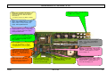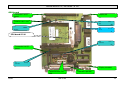
1
Service Manual TDI / XXTREME / S TDI
Service Manual
TDI / XXTREME / S-TDI
01/02
Rev. 2.09
1
Service Manual TDI / XXTREME / S TDI
Contents
General notes .................................................................................................................... 4
Copyright ......................................................................................................................................... 4
Error handling and search.................................................................................................. 5
Data transmission ............................................................................................................................ 5
Display ............................................................................................................................................. 6
Punch recognition ............................................................................................................................ 6
Material transport............................................................................................................................. 7
Ribbon - Ribbon guiding .................................................................................................................. 8
Feed Roller ...................................................................................................................................... 9
Position of Print Format ................................................................................................................... 9
Print Quality ................................................................................................................................... 10
Feed Unit ....................................................................................................................................... 11
Memory Card ................................................................................................................................. 11
Service............................................................................................................................. 12
Mechanic ....................................................................................................................................... 12
Stock magazine ....................................................................................................................... 12
Cover ....................................................................................................................................... 14
Front cover .............................................................................................................................. 14
Print module ............................................................................................................................ 17
Feed unit.................................................................................................................................. 18
Pressure unit ........................................................................................................................... 20
Thermal head .......................................................................................................................... 21
Gap sensor .............................................................................................................................. 25
Ribbon transport ...................................................................................................................... 26
Ribbon rewind axle .................................................................................................................. 27
Ribbon guiding......................................................................................................................... 29
Exchanging the print head....................................................................................................... 32
Print head adjustment.............................................................................................................. 32
Material feed............................................................................................................................ 32
Lift mechanic ........................................................................................................................... 33
Short Tag Option (second feed for short label) ....................................................................... 40
Electronic ....................................................................................................................................... 46
Display..................................................................................................................................... 46
Transformer ............................................................................................................................. 47
Power connector...................................................................................................................... 47
I/O board.................................................................................................................................. 48
Option board............................................................................................................................ 49
CPU board............................................................................................................................... 49
Sensors.................................................................................................................................... 50
Material end sensor ................................................................................................................. 51
Speed sensor .......................................................................................................................... 52
Magazine sensor ..................................................................................................................... 53
Separator sensor ..................................................................................................................... 54
Magazine end sensor .............................................................................................................. 55
Gap sensor .............................................................................................................................. 56
Printhead sensor ..................................................................................................................... 58
01/02
Rev. 2.09
2
Service Manual TDI / XXTREME / S TDI
Ribbon end sensor .................................................................................................................. 59
Fan 59
Connector thermal print head.................................................................................................. 61
Power connector...................................................................................................................... 63
Fuse......................................................................................................................................... 63
Interface connector.................................................................................................................. 64
Factory adjustment .................................................................................................................. 65
Set data to zero ....................................................................................................................... 65
Change service data................................................................................................................ 66
Appendix.......................................................................................................................... 68
Tooling and work material.............................................................................................................. 68
Layout TDI ..................................................................................................................................... 69
Diagrams ....................................................................................................................................... 70
CPU board - configuration....................................................................................................... 70
Output stage board.................................................................................................................. 72
CPU board............................................................................................................................... 74
Lifting table contol.................................................................................................................... 75
Index................................................................................................................................ 76
01/02
Rev. 2.09
3
Service Manual TDI / XXTREME / S TDI
General notes
Copyright
This User Manual and its contents are subject to copyright. The publisher’s prior written
consent must be obtained for reproduction of the manual as a whole or part thereof.
Names are generally given without any reference to existing patents, registered patterns or
designs, or trademarks. The omission of a corresponding note does not imply that the names
can be used freely. All trademarks are acknowledged.
The manufacturer reserves the right to technical and other alterations without prior notice.
The publisher cannot warrant the accuracy of the content of this manual.
Note: Please follow the notes shown in this text - it will help to cover all situations and
keep your engine working. .
01/02
Rev. 2.09
4
Service Manual TDI / XXTREME / S TDI
Error handling and search
To verify functionality of mechanical and electronically functions - if there is not an
evidently defect - use status report ‘ STA0 to STA3 ‘ (see User Manual) - printout to
check the unit.
Data transmission
characteristic
possible reason
solution
missing or defective wrong connection
data
wrong interface
01/02
check interfaceconnection
check parameter IFAC
parameter wrong
check parameter
BAUD, PARI, SBIT,DBIT,
HAND (only with serial interface)
connector pin assignment
wrong
change wire or pin
assignment (assignment
see Easy Plug Manual)
wrong handshake
check parameter
(only with serial interface)
emulation
use standard font set
loosen board connector
check and perhaps plug in
defective board
check and perhaps change
distance to wide
reduce length of wire
Rev. 2.09
5
Service Manual TDI / XXTREME / S TDI
Display
characteristic
dark display
key function
faulty
possible reason
no power
solution
check (perhaps change fuse)
see fuse)
loosen connector
check and perhaps plug in
defect display
check and perhaps change
main board defect
check and perhaps change
loosen connector
check and perhaps plug in
key defect
check and perhaps change
display board
main board defect
check and perhaps change
Punch recognition
characteristic
possible reason
solution
status ST05 mechanical sensor position adjust mechanical sensor position
with material in the not adjusted correctly
sensor
gap not found
sensor defect
check with „SCHK“ and perhaps
change (see user manual)
sensor adjustment wrong
change sensor sensibility with
parameter ‘PUNS’
wrong sensor selected
check Sensor REFL or NORM
print positionnot
recognised gap position
in the prog. position is changing - reasoned
by gap contour
01/02
adjust zero position with
parameter ‘PUNO’
Rev. 2.09
6
Service Manual TDI / XXTREME / S TDI
Material transport
characteristic
possible reason
solution
sloping material
unfavourable position of
(infeed)
pressure roller
no material
transport
unfavourable position of
pressure roller
check and if necessary adjust
check and if necessary adjust
adjustment of pressure
spring
check pressure and perhaps
adjust
connector of stepper
loosen
check and perhaps
plug in
stepper motor defect
check and perhaps change
main board defect
check and perhaps change
feed key defect
check and perhaps change
display board
media is moving
media guiding wrong
adjusted
check and perhaps adjust
no media transport
empty magazine
fill magazine
no material feed
magazinenot in uppercheck and adjust
position
feed rollerdirty
check and clean
separate crevasseto small
check and adjust
more label then one separate crevasseis to
is moved
wide
check and adjust
synchronisation of
sensor defect
media movement is
wrong
check with ‘SCHK’ - see user
manual and change
sliding feed roller
check and clean
label platform is not stepper motor defective
moving
01/02
check and change
Rev. 2.09
7
Service Manual TDI / XXTREME / S TDI
label platformis
running to upper
position
wire not connected
check and plug in
optional board defect
check and change
loosen spindle
check and fix
reflective eye in the
magazineis dirty or
defective
check sensor with ‘SCHK’
see user manual and change or
clean
sensor defect
check with ‘SCHK’ and change
label platformis
stop switch defect
moving against lower
stop position
check with ‘SCHK’ - see User
Manual - and change if necessary
Ribbon - Ribbon guiding
characteristic
possible reason
solution
ribbon end message ribbon unwind pin is not
without reason
rotating
fix ribbon core on pin (using
spring leaf) - if the thread is stripped
move the spring leaf to an other pos.
wrong parameter
check parameter FOIL and perhaps
change
sensor defect
check and perhaps change
(see SCHK - user manual)
ribbon unwind pin blocked
check and perhaps loose
ribbon rewind defect
check and perhaps repair
ribbon wrinkle
wrong adjustment of
ribbon rewind friction
check and adjust friction
ribbon is not rewinded correctly
wrong adjustment of
ribbon rewind friction
round belt defect
check and adjust friction
wrong adjustment of
check and perhaps adjust
ribbon is rewound
01/02
check and perhaps replace
Rev. 2.09
8
Service Manual TDI / XXTREME / S TDI
around ribbon
transport axle
ribbon rewind friction
round belt defect
check and perhaps replace
ribbon breaks during high print temperature
printing process
check adjustment with parameter
HVxx and reduce if possible
HRES wrong adjusted
check resistor of thermal head
and change if necessary
possible reason
solution
Feed Roller
characteristic
abrasion
high print speed
color deposit
deformation
replace roller
pressure of thermal head
to high
check and perhaps adjust
pressure roller not on
material
check and adjust
material deposit
cleaning (detergent 98925-00)
ribbon print directly to
feed roller
cleaning and avoid printing
direct to feed roller
(detergent 98926-00)
direct pressure to feed
roller
avoid direct pressure
long distance printing
replace roller
high temperature of
thermal head
check adjustment (HVxx)
and perhaps change
damaging by user
change feed roller and train
user
Position of Print Format
characteristic
possible reason
print position
wrong parameter
not in prog. position
01/02
solution
YPOS parameter or #J - Easy Plug .
command - check and perhaps
change
Rev. 2.09
9
Service Manual TDI / XXTREME / S TDI
print transversally
to document
gap position is recognised
wrong - reasoned by gap
contour
adjust with parameterPUNO
material guiding to
strong
check and perhaps adjust
pressure roller adjustment
wrong or not positioned
check and adjust
material guiding not
adjusted well
check and perhaps adjust
thermal head not in
zero position
check and adjust
possible reason
solution
Print Quality
characteristic
faint print
contaminated or damaged
thermal head
clean or replace thermal head
wrong electrical adjustment check parameter HVxx
of thermal head
position of thermal head
to feed roller
check mechanical adjustment
wrong pressure of
thermal head
check and perhaps adjust
ribbon and media do not
match
check media and ribbon type
aged ribbon
new ribbon
bad or changing
damaged or contaminated
imprint
feed roller
check and perhaps clean or replace
feed OK - but no
imprint
temperature of thermal
head (less)
check adjustment (HVxx)
wrong side of ribbon
check and perhaps change
01/02
Rev. 2.09
10
Service Manual TDI / XXTREME / S TDI
thermal head not in print
position
check and perhaps adjust
thermal head not fixed on
axle
fix screw
thermal head defect
check thermal head and perhaps
change
thermal head wire notcheck and perhaps plug in
connected
main board defect
check and perhaps change
possible reason
solution
Feed Unit
characteristic
no material transport wrong adjustment of
pressure roller
check and adjust
belt defect
check and perhaps replace
stepper motor defect
check and replace if necessary
board defect
check and replace
characteristic
possible reason
solution
memory card is not
recognised
contaminated contact
check and if necessary clean
card not initialised
check and initialise
card defect
check and perhaps replace
Memory Card
type of card is not released check and change
01/02
Rev. 2.09
11
Service Manual TDI / XXTREME / S TDI
Service
Mechanic
Stock magazine
The stock magazineis used to store the printed label / strip - it is not a stacker - so be
aware that the function is limited.
Disassembly - Assembly
to assemble slide the two guiding
axle into the printer
the magazineshould touch the printer
cover
to guide the label / stripon the outer
side adjust the guide stick
adjust the end position with the magnetic
round stick
not all label sizes can be stored in the
same height - use the platformto find
the correct height for your label
01/02
Rev. 2.09
12
Service Manual TDI / XXTREME / S TDI
Guide stick
The guide stick is used to fix the label / stripon the outer side of the printed label /
strip - with this unit the labels are stored in a functional way. To remove the label
it is necessary to move the guide stick into the upper
position - it will be fixed there.
Disassembly - assembly
loosen the hexagonal screws and the
rear cover can be removed
the fixation part can be removed from
the axle - and if necessary be
changed
the spring loaded pressure pieces
catch to the holes and give a fixed
position
be aware of the cover fixation points
during assembly
to cover the guiding stick in a save way
please attach the plastic cape to the
stick
Tooling
cross recessed head size 1
01/02
Rev. 2.09
13
Service Manual TDI / XXTREME / S TDI
Cover
Remove the unit from power before opening the cover ! Only authorised personal is
allowed to open the cover.
Attention : Opening the cover - unplugged - is dangerous to your life !
Front cover
Disassembly - assembly
loosen the cover screws
( 2 x 2 cross recessed screws)
the front cover can be removed
completely
the front cover consists out of a
metal part around - and a front part
out of two plastic parts
metal - and plastic front are mounted
together with 5 hexagonal head screw
an additional snap in piece in the upper
part of the metal cover gives more
stability to the front cover
open the hexagonal head screws slightly
and pressing down the snap in piece
- the front part can easily be removed
if necessary the front plate can now
be removed
Tooling
cross recessed head size 1
hex socket wrench size 6
01/02
Rev. 2.09
14
Service Manual TDI / XXTREME / S TDI
Rear cover
Disassembly - assembly
loosen 10 cross recessed screws
in front - and 3 cross recessed
screws backwards the rear metal
cover can be removed
Attention: Mounted to the metal
cover you will find the fan - the
fan is mounted as well to the board!
disconnect the fan from the I/O board
the display cover will stay to the unit
Tooling
cross recessed head size 1
screw driver small
Display cover
01/02
Rev. 2.09
15
Service Manual TDI / XXTREME / S TDI
Disassembly - assembly
remove rear cover
(see rear cover)
loosen two cross recessed screws -
and the display cover can be removed
display and cover are fixed together
loosen one cross recessed head screw
and the display can be separated from
the cover
unplug the display from the CPU board
Tooling
cross recessed head size 1
01/02
Rev. 2.09
16
Service Manual TDI / XXTREME / S TDI
Print module
The print module can be removed completely
from the printer.
Built to the cast-metal case are the feed unit,
the material guiding, ribbon unwind, ribbon
rewind and ribbon transport.
As well the parts belonging to this components.
Disassembly - assembly
remove the rear cover (see cover )
unplug stepper motor and sensor
connector
remove ground wire from the main cover
remove board and board carrier
(see electronic)
loosen fixation screws of print module
( 8 hexagonal screws)
Tooling
hexagonal socket 3 mm
cross recessed head size 1
01/02
Rev. 2.09
17
Service Manual TDI / XXTREME / S TDI
Feed unit
The complete feed unit assembly consist of feed roller (2 pieces), pressure unit,
thermal head assembly, material guiding and gap sensor.
Feed roller
Disassembly
remove the rear cover (see cover)
loosen feed stepper motor and
remove ( 3 self locking hex nut’s )
remove toothed belt
loosen thermal head (knurled screw)
and open
remove lock washer from gear and
loosen gear from feed axle - remove gear
(small screw driver)
remove tab washer on the out side
( 2 hexagonal screws)
remove feed roller to the out side
Assembly
assemble feed roller (1 and 2)
mount tab washer, assemble gear
and fix with lock washer
check free run of roller
01/02
Rev. 2.09
18
Service Manual TDI / XXTREME / S TDI
Tooling
hex socket wrench SW 7
hexagonal socket 2,5 mm
screw driver medium size
01/02
Rev. 2.09
19
Service Manual TDI / XXTREME / S TDI
Pressure unit
Two adjustable pressure roller belong to the pressure unit - the pressure to the feed
roller can be removed by pressing the red lever on the out side.
Then manual feed of material - forwards and backwards - is possible.
Disassembly
remove rear cover ( see cover)
remove contact pressure - unhinge
spring
remove inner lock washer
remove outer lock washer
withdraw axle
change pressure roller if necessary
Assembly
insert axle
fix inner and outer lock washer
hinge contact pressure spring
adjust pressure roller to position
Tooling
pincer for lock washer
pincer
01/02
Rev. 2.09
20
Service Manual TDI / XXTREME / S TDI
Thermal head
The thermal print head is a high sensitive unit - mainly sensitive against static
electricity ! Be aware - before touching the thermal head - that you remove static
electricity from your body. As well if the printhead is disassembled.
The damage is not - visible - ad once ! It is possible that the static works for a period
of time - and then blow the head.
Mounting support
Disassembly
Attention: Before following the next steps
- remove the printer from power supply.
loosen the print head with knurled screw
swing out of the way the thermal head
(cleaning position) and unplug power- and signal
connector
open both fixation screws ( 2 hexagonal screws)
Discharge ! Carefully remove the thermal
print head out of the guiding pins.
01/02
Rev. 2.09
21
Service Manual TDI / XXTREME / S TDI
Assembly
Discharge ! Insert thermal print head to
guiding pins
Fix with both screws
plug in - power and signal connector and
fix head with knurled screw
Tooling
hexagonal socket 2,5 mm
Adjustment
Has a thermal print head to be replaced, it could be - reasoned by manufacturing
tolerances in this part, necessary to adjust the part ! A factory adjustment was done
before - if possible this adjustment should not be changed.
by factory adjustment - the position bar
is adjusted with a tool to a fixed position
the manual adjustment is done by two screws
(hexagonal) in the front area of the mounting
support profile
moving the screw clockwise will move the thermal
head backwards - turning counter clockwise
will move the print head forwards
to adjust the print head - all 5 hexagonal screws
have to be opened
using the both hexagonal screws in front of the
profile - the thermal head has to be adjusted to a
perfect print position (best print result !)
fix the 5 hexagonal screws again
Tooling
hexagonal socket 2,5 mm
hexagonal socket 1,5 mm
01/02
Rev. 2.09
22
Service Manual TDI / XXTREME / S TDI
Contact pressure
The thermal head is pressed with a constant pressure against the material and feed
roller - done by an adjustable spring .
Given by the media width - or thickness this pressure has to be adjusted !
in the unit there is a pressure adjust element
- to reach from the outside three levels of pressure are available
a spring loaded pressure part fits into the
decided position and fix the pressure to the
selected value
pressure adjustment
spring
balance
Assembly / Disassembly
fix screw
loosen the lock washer - remove the screws and
unhinge the spring - then the adjustment knob
can be removed.
Adjustment
- adjustment knob to level small
(short stroke)
- connect coupling part with spring
- loosen security screw
- adjust by using a spring balance a torque
of 8N
- fix with screws
The value for level middle and wide are adjusting
automatically !
8N
Tooling
pincer lock washer
spring balance 0-50 N
fork spanner SW 7
coupling part
01/02
Rev. 2.09
23
Service Manual TDI / XXTREME / S TDI
Material guiding
The material guiding is - built on two axle - fixed with two clamping rings in the left
and right base plate. The outer media guiding is adjustable - by moving the guiding
free on the axle - the inner one is fixed on the zero line.
Mounted to the inner guiding is the media end sensor !
Disassembly
loosen clamping rings on the outer side
remove axles
disassemble media guiding (attention to media end
sensor)
Assembly
assemble material guiding and axles
(attention to sensor)
adjust inner and outer clamping rings
(perhaps fix with glue if necessary)
adjust inner guiding to zero position -
move outer guiding to media width
01/02
Rev. 2.09
24
Service Manual TDI / XXTREME / S TDI
Gap sensor
The gap sensor (standard through light - optional reflective) is mounted to a plastic
part. Adjustment to the correct position can be done by the red adjustment knob - to
reach from outside.
Disassembly
loosen hexagonal screw inside of adjustment
knob
remove gear , toothed belt from feed roller 1 and 2
(see feed roller)
sensor mechanic can be removed backwards -
and if necessary replaced
Assembly
grease the sides of the sensor mechanic
and insert
assemble feed system (see feed roller)
fix adjustment knob with cross recessed screw
(be aware of zero position)
check sensor mechanic for easy moving
Tooling
cross recessed head size 1
01/02
Rev. 2.09
25
Service Manual TDI / XXTREME / S TDI
Ribbon transport
The ribbon transport - consist out of ribbon unwind, ribbon turning axle, ribbon
transport axle and ribbon rewind axle - as well as the ribbon saving system, is
together with the material handling the second important part of the print module.
Ribbon unwind axle
Disassembly
unhinge brake spring and open self secure nut
timing disc
loosen spring cover part - to remove the timing disc
disassemble the foil end sensor
remove limiting ring, spring, and timing disc
as well the belt disc
ribbon end
loosen of both hexagonal screws and remove
bearing shell - then the ribbon axle can be removed
to the front side
Assembly
insert ribbon axle - assemble bearing shell
- fix with both hexagonal screws
assemble belt disc and timing disc
spring
fix spring, limiting ring and spring cover part
with self secure nut
assemble ribbon end sensor and check sensor
check function of unwind break and round run of
unwind axle
friction
spring
Tooling
fork spanner SW 7
hexagonal socket 2,5 mm
01/02
Rev. 2.09
26
Service Manual TDI / XXTREME / S TDI
Ribbon rewind axle
Disassembly
unhinge round belt and loosen self secure nut
loosen spring cover part and limiting part,
remove spring and break disc as well the
round belt disk
loosen both hexagonal screws and remove
bearing shell, move ribbon axle outside
round belt
Assembly
insert ribbon axle and bearing shell, assemble
round belt disc and break disc
spring, limiting part and spring cover part fix
again with self secure nut
assemble round belt
Tooling
fork spanner SW 7
hexagonal socket 2,5 mm
Ribbon zero line adjustment
Moving zero line disc of unwind and rewind pin gives the possibility to separate
media and ribbon zero line.
01/02
Rev. 2.09
27
Service Manual TDI / XXTREME / S TDI
Adjustment
loosen hexagonal screw in zero line disc
move disc to new position and fix
with hexagonal screw to new position
Tooling
hexagonal socket 2 mm
01/02
Rev. 2.09
28
Service Manual TDI / XXTREME / S TDI
Ribbon core break
Changing the position of the spring leaf gives more or less friction to the ribbon core.
loosen cross recessed screws and adjust
spring leaf to new position (A)
fix spring leaf with screws
if a thread is stripped - move the spring leaf
to a slightly new position and fix again (B)
a new thread will be the result
Tooling
cross recessed head size 1
Ribbon guiding
This axle is used to feed the ribbon without touching other parts into the thermal
print head.
guidance unit
Disassembly / Assembly
loosen screw in the cast metal case
remove guidance unit to the front side
Tooling
box spanner SW 10
01/02
Rev. 2.09
29
Service Manual TDI / XXTREME / S TDI
Ribbon feed / -roller
Normal ribbon transport and material transport are running with the same speed
1 : 1. The ribbon transport is done by the ribbon transport axle - rewind is done via
friction clutch and the used ribbon is rewound to the rewind axle. If the ribbon saving
system is activated the thermal print head is moved away from the feed roller - the
stepper motor stops and only material is fed.
Disassembly
contact
spring
loosen the three nuts to remove the ribbon
stepper motor - unhinge round belt and
remove the stepper motor
loosen of lock washer
lock
remove gear
the ribbon transport axle can be removed
to the front side
Assembly
insert ribbon feed roller from front side
assemble gear and fix with lock washer
- check if roller is moving round and easily
fix stepper motor with the 3 nuts - check that
the tooth of the gears fit
suspend round belt
Tooling
box spanner SW 7
01/02
Rev. 2.09
30
Service Manual TDI / XXTREME / S TDI
Ribbon end sensor
The ribbon end sensor is used to recognise a broken ribbon or end of ribbon !
A moving timing disc is watched constantly .
Assembly / Disassembly
loosen hexagonal screw
change sensor if necessary
fix sensor with hexagonal screw
ribbon end
Tooling
hexagonal socket SW 2,5
Ribbon saving mechanism
The ribbon saving mechanism is working by moving the thermal head away from the
feed roller - stop the stepper motor for the ribbon transport - and feed only material.
Disassembly / Assembly
loosen the sensor for head home position
by opening the cross recessed screw
unhinge the pressure spring
remove stepper motor for head movement
by opening the three hexagonal screws
the timing disc can be rotated after opening of
one hexagonal screw
the lever can be untied by loosen the hexagonal
screw
disassemble pressure disc by opening of one hexagonal screw and remove disc from the
axle
01/02
Rev. 2.09
31
Service Manual TDI / XXTREME / S TDI
Exchanging the print head
Note: For a description refer to the Service Manual TTX x50/Wildcats, topic
section "Service Print Module", chapter "Removing the print head".
Print head adjustment
Note: For a description refer to the Service Manual TTX x50/Wildcats, topic
section "Service Print Module", chapter "Adjusting the print head
position".
Material feed
The media feed consist out of lift table - the consisting lift mechanic, the label
stop and the separator. Controlled is the system by the sensor - material speed,
material position and magazine - end position. The material feed can be used for
single label, strips and fan folded label.
Lift table
The lift table is used to store the label stock. Out of this label stock the label is
separated and fed into the print module.
Disassembly - Assembly
loosen the two lock washer and the lift table
can be removed from the axle’s
Tooling
small screw driver
Label stop
The label stop is used to stop the label stock at a defined zero position.
Disassembly - Assembly
loosen both cross recessed screws
and the label stopper can be removed
Tooling
Cross recessed head size
01/02
Rev. 2.09
32
Service Manual TDI / XXTREME / S TDI
Lift mechanic
The lift mechanic is used to move the label platform to the correct position - the
movement is controlled by a infra red sensor - the zero position in the lower end is
controlled via a micro switch.
The ‘play together’ of this components is very critical and has to be adjusted very well
- otherwise the label separator is not working.
Note: To work on this unit it has to be disassembled completely ! Only the
moving weal can be removed without disassembling the lift mechanic !
Disassembly - Assembly
remove the rear cover
(see cover)
disassemble board and board
carrier ( see electronic)
remove lock washer from feed axle
and the feed roller can be removed
- if necessary clean !!!!!
loosen the hexagonal screws and the
lift mechanic can be removed
Tooling
Hexagonal socket 3 mm
cross recessed head size 1
screw driver
01/02
Rev. 2.09
33
Service Manual TDI / XXTREME / S TDI
Lift motor
The lift motor is moving the label platform together with the label stock. Using the
display key’s UP an DOWN the label platform can be moved manual !
The motor and the thread axle are glued together - they can be changed only as an
assembly.
torque =30
Disassembly - Assembly
remove rear cover (see cover)
disassemble board and carrier
(see electronic)
disassemble lift mechanic
(see lift mechanic)
loosen lower metal casting plate
( 2 hexagonal screw)
remove fork nut from thread axle
clean new motor and axle by using aceton
glue before mount
Loctite 648
glue motor and axle together using Loctite 648
and assemble the unit again
adjust fork nut – 20 mm from the lower end
the unit has to stand vertically then press the
min. 20 mm
block down
the glue is hard 30 minutes later – but you can
assemble the unit immediate
loosen the two screws - the motor is
mounted with - motor and thread axle
can be removed
press down
Tooling
hexagonal socket 2,5 mm
hexagonal socket 3 mm
cross recessed head size 1
01/02
Rev. 2.09
34
Service Manual TDI / XXTREME / S TDI
Magazine end switch
The switch is used to stop the label magazine in the lower end position. The sensor
can be checked via display ( see electronic) !
Disassembly - Assembly
loosen the two hexagonal screws - and
the switch together witch the metal mounting
plate can be removed
Tooling
micro switch
hexagonal socket 3 mm
Magazine sensor
This sensor is used to control the moving speed of the label platform. The platform is
running up with high speed as long as the sensor is not covered by label material.
As soon as the sensor is covered - the lift motor frequent is changed to lower speed.
The function can be checked via display (see electronic) !
Disassembly - Assembly
the sensor can be dismounted - by using a
pin to move out the defective sensor
clean the hole and glue the new sensor in
sensor
Tooling
pin
glue
Attention : The sensor should be one the same level as the front plate (surface) !
01/02
Rev. 2.09
35
Service Manual TDI / XXTREME / S TDI
Separator sensor
This sensor is used to move the upper side of the label stock - after one label (strip is
removed - to the level before.
The sensor can be checked via display ( see electronic) !
Disassembly - Assembly
loosen screw - and the sensor can be
removed and if necessary be changed
Tooling
cross recessed head size 1
hexagonal socket 3 mm
Adjustment
loosen screw to adjustment plate
move measurement (6mm) into
sensor and fix plate
tie screw
fixation screw
measurement 6 mm
Attention : The spring has to be mounted in the lower hole !
01/02
Rev. 2.09
36
Service Manual TDI / XXTREME / S TDI
Feed motor
This stepper motor feeds - after successful separation - the label into the print module
The complete separator unit is spring loaded.
Disassembly - Assembly
the lock washer has to be removed
by using a screw driver
loosen the hexagonal screw - and the
positioning part can be removed
remove lock washer with pincer
motor can be removed - look to the spring
remove feed weel from motor
change stepper motor if necessary
Tooling
pincer
hexagonal socket 2 mm
hexagonal socket 2,5 mm
hexagonal socket 3 mm
01/02
Rev. 2.09
37
Service Manual TDI / XXTREME / S TDI
Feed roller
This roller is used to move the media from the seperator to the print modul. The roller
has to be cleaned in regular distance !
Disassembly - Assembly
the feed roller can be disassembled without
disassembling the lift mechanic complete
remove the lock washer from the feed
axle
Attention : The roller must be cleaned
regular !
Tooling
screw driver
cleaning fluid
Separator edge
The separator edge is used to feed only ‘one’ label via the separator to the print
module. the separator edge can be adjusted ! The width of the slot has to be more
then the width of one label and less then the width of two label !
Disassembly - Assembly
remove the complete lift mechanic
adjust separator edge new - or remove it
separator
the pressure spring can be changed
01/02
Rev. 2.09
38
Service Manual TDI / XXTREME / S TDI
loosen the self secured hexagonal nut
and separator edge - springs and adjustment
knob can be changed
remove the adjustment knob together with the
marker from the separation edge
the springs can be changed as well
check during assembly that the parts are
fitting together and move easily
Tooling
measurement
fork spanner SW 6
Adjustment
to adjust the separator follow this steps
adjust separator edge with the adjustment knob to zero position - the 4 washer are
the limit
then open the self secured nut until the opening between nut and separator edgeis
0.9 mm
adjustment
adjust with measurement part
washe
adjustment value
0 9mm
self secured
nut
01/02
Rev. 2.09
39
Service Manual TDI / XXTREME / S TDI
Short Tag Option (second feed for short label)
This option was developed to handle short label (from 50 up) with the unit. This is
normally not possible. The so called short tag option is a second feed driven by the
feed roller
The label is ejected through the separator – overtaken by the short tag optionand
driven to the main drive
Attention: The option can be mounted to a unit with a serial number higher then
SN 04731xxxx-xxx ! This can be done only by a service technician.
Disassembly - Assembly
remove pressure from the pressure roller on the feed axle by unhinge spring (the spring
will be changed later to a new one)
the feed roller has to be disassembled, as well the axles of the media guiding and the
guides
The guides are not more used with the short tag option – the sensors used before
(mounted and glued to the inner guide) are replaced by a new sensor.
remove the axle 1 of the assembly (open two hexagonal screws)
axle 1
hexagonal screw
01/02
Rev. 2.09
40
Service Manual TDI / XXTREME / S TDI
remove tighten roll, roll 1 and the fixation ring – you will need them later
fixation ring
roll 1
tighten roll
the pressure roller have to be removed with the axle
pressure
loosen the second axle by opening the two hexagonal screws
axle two
01/02
hexagonal screw
Rev. 2.09
41
Service Manual TDI / XXTREME / S TDI
assemble the short tag option and the new feed roller together – watch carefully the belt
and how the belt is guided. The belt has to run around the feed roller and the two gears
mounted to the axle.
touthed belt
insert axle 1 again – assemble roll 1, fixation ring and tighten roll to the axle – insert the
axle into the bush of the steal plate – the assembly is hanging down
remove second axle – add the bush of 8 mm between assembly and steal plate
- move the short tag option up and insert the second axle
distance bush
the transport axles have to run very smooth – the inner screws on the axle 1 and axle 2
tighten ( the inner plate is pressing against the bush – the bush against the steal plate)
move the outer plate in a way that the axles have between 2/10 and 3/10 mm movement
the axles have to run smooth and easy – then tighten the first and second axle
01/02
Rev. 2.09
42
Service Manual TDI / XXTREME / S TDI
now use the hexagonal screw in the outer plate to adjust the assembly between the two
feed block plates – the complete block is moved into the direction of the steal plate and
fixed
fixation
assemble the pressure roller again – be aware of the washer – they are used to give a
distance of 2 mm
2
change the pressure spring against the new spring
01/02
Rev. 2.09
43
Service Manual TDI / XXTREME / S TDI
change the lever position on the axle 90 degree
insert power stacker preparation, 5 pin connector at the rear side of the cover, 4 pin
connector to CN 23 and 6 pin connector to CN 26 on the I/O board
CN 23
01/02
Rev. 2.09
CN 26
44
Service Manual TDI / XXTREME / S TDI
the turn away parts have to be assembled in the following way to the profile
1 plastic part (s) (thicker part up!)
2 turn away foil
3 glass fiber cover
plastik
plastic
foil
foil
glass
connect the sensor to CN 17 I/O board – check that the media end sensor is out of
function by using sensor menu point M xx, check that M 15 is shown on the display
CN 17
activate the short tag option using menu point SECF (select YES)
OFF
INFO
PRTP
IFAC
SYSP
EMUL
NACH
SENS
PUNS
FMOD
OMOD
SMOD
MMOD
LPOS
SECF
01/02
Rev. 2.09
YES?
45
Service Manual TDI / XXTREME / S TDI
Electronic
Before working on the electronic - remove the printer from power ! Discharge static
from your body - before touching electronic parts.
Follow the security tips - working with electronic devices. Only trained people are
allowed to do this work !
Display
display connector
Disassembly - Assembly
opening the rear cover - then it is possible to
unplug the connector from the CPU board
unplug connector from the CPU board
loosen two cross recess screws and remove
display together with cover
loosen one cross recess screw and you can remove
the display from the cover
check that the display cable is running without
touching edges or is bent
Tooling
cross recessed head size 1
01/02
Rev. 2.09
46
Service Manual TDI / XXTREME / S TDI
Transformer
Before working on the electronic - remove the printer from power !
Disassembly - Assembly
remove rear cover - unplug all transformer
wires from filter unit - and I/O board
( plug and wire position see diagram)
loosen fixation screw at the bottom of
the cover ( 1 hexagonal screw)
the transformer can be removed if necessary
Tooling
hexagonal socket 5 mm
Power connector
Filter - main switch, power select switch and the fuse cover are part of the power
connector. Only the fuses can be changed separate - all other components belong
together.
Attention: Unplug unit from power - before working on this device !!!
Disassembly - Assembly
change fuses - by removing the fuse cover and
change the blown fuses
use only the correct value of fuse !!!!!
01/02
Rev. 2.09
47
Service Manual TDI / XXTREME / S TDI
unplug transformer from filter unit
loosen two cross recess head screws and remove
the filter unit
Tooling
cross recessed head size 1
I/O board
The I/O board is the board m controlling stepper motors, sensor’s - power supply and
options !
Adjustment will be done on this board if necessary - as well all connectors are placed
on this board - without interface’s and display.
Disassembly - Assembly
loosen all connectors
loosen all fixation screws
- 3 cross recess screws for the board
- option board 1 hexagonal screw
carefully remove the I/O board from the CPU
board
check that the pins are not damaged during
connecting / disconnecting
Adjustment
see sensor
Tooling
cross recess head size 1
01/02
Rev. 2.09
48
Service Manual TDI / XXTREME / S TDI
Option board
Optional board’s are board’s - like cutter board or other - used for special applications
or other optional features of the printer. It is not only the board - sometimes it can
consist out of board, cable and connector !
Disassembly - Assembly
loosen connector’s
loosen fixation screws
remove carefully the optional board
CPU board
The CPU board is the board - controlling the complete unit ! Build to the board is the
processor - memory - interfaces (RS 232 - Centronics - RS 485 optional) displayconnector and program / font memory !
Disassembly - Assembly
disassemble the I/O board and maybe
optional board (see I/O board)
unplug connectors (display - interfaces)
loosen fixation screws ( 3 cross recess screws
1 bolt) - the board can be replaced if necessary
check during assembling the wires are
running free
check during board assembly that the pins
are connecting correctly and are not
damaged
Tooling
fork spanner SW 7
cross recess head size 1
01/02
Rev. 2.09
49
Service Manual TDI / XXTREME / S TDI
Sensors
A sensor is eye ear and feeling for the printer. Printer sensor’s are gap sensor, ribbon
endsensor, material end sensor, head position sensor, knife home sensor, cover
switch and maybe optional sensor’s.
All these sensor’s can be checked - and some adjusted to a defined value.
Sensor adjustment overview
Sensor
Setting condition
Pot.
Gap sensor
(transmission)
without material (sensor
free)
with material
without material, hood
closed
with material
Reflex mark
white material
no sensor connected
sensor over a hole of the
oszillator disc (sensor free)
P7
Gap sensor
(Reflex)
Ribbon end sensor
Test
point
P5
P8
CN34
sensor covered
Printhead sensor
(Head position)
P4
sensor over gap (sensor
free) (autoecon. position,
printhead raised)
Sensor covered
(print position, lowered)
Test point:
Value
CN32
Display:
Parameter
Display:
Value
Pxxx
7
Rxxx
>7
7
Turn P8 anti- Fxx
clockwise to
the limit.
>2.5 V
Turn P4 anti- Hxx
clockwise to
the limit.
>2.5 V
>7
0...9
10...255
0
0
15
0
15
Hood switch
Hood closed
Hood open
Material end sensor
without material (sensor
free)
with material
P1
Speed sensor
without material
with material
P9
CN33
<0.3 V
>2.5 V
Oxx
0
15
Separator sensor
Magazine at top position
(sensor free)
Magazine not at top pos.
P2
CN31
<0.3 V
Uxx
0
0
15
<0.3 V
Mxx
0
15
>2.5 V
Magazine at bottom position
Magazine not at bottom pos.
Magazine sensor
(Reflex)
without material (sensor
free)
with material
P6
Printhead
R25
01/02
Cxx
>2.5 V
Magazine Limit
Switch
Printhead voltage
CN30
check
check
check
check
CB14
15
Dxx
0
15
Sxx
0...2
max. Wert
CN29
Rev. 2.09
25.5 V
50
Service Manual TDI / XXTREME / S TDI
CAUTION! – Don´t use the housing but the ground contact on the I/O board when setting the
printhead voltage! Otherwise you will set the voltage too high, what will damage the
printhead.
Material end sensor
The material end sensor is used - before parts of the printer are damaged (thermal
head or other) - to stop the unit and display the status !
Disassembly / Assembly
the material end sensor is placed in the
inner material guiding - positioned at the
front plate
to assemble / disassemble see material
guiding
the sensor is glued to the guiding and
can be replaced only as assembly
Adjustment
Connector : CN 9
Test point : CN 30
Parameter : M xx
- see diagram -
check the sensor using parameter (SCHK) adjustment is described in user manual
via menu select point M xx
without material - display ‘M 0‘ - adjust a value of < 0.3 V at test point CN 30 with
pot P1
with material ‘M 15’ is displayed
01/02
Rev. 2.09
51
Service Manual TDI / XXTREME / S TDI
Speed sensor
This sensor is used - to lower the media speed for a short time - before the label is
introduced into the feeding system of the print module.
Disassembly - Assembly
the speed sensor is mounted into the inner
side of the media guiding
to assemble / disassemble see material
guiding
the sensor is glued to the guiding and can
be replaced only as assembly
Adjustment
Connector : CN 17
Test point : CN 33
Parameter : O xx
- see diagram -
check the sensor using parameter (SCHK) adjustment is described in user manual
via menu select point O xx
without material - display ‘O 0’ - adjust a value of < 0.3 V at the test point CN 33 using
pot P9
with material ‘O 15’ is displayed
01/02
Rev. 2.09
52
Service Manual TDI / XXTREME / S TDI
Magazine sensor
This sensor is used to adjust the speed of the platform to separate the label from the
stock and feed it int the print module.
Disassembly - Assembly
the magazine sensor is glued into the front plate
to disassemble / assemble see lift mechanic
be aware that the sensor is glued into the plate
Adjustment
Connector : CN 14
Test point : no
Parameter : S xx
- see diagram -
check the sensor using parameter (SCHK) adjustment is described in user manual
select the menu point ‘S xx’
a not covered sensor has to show a value of 0 - 2
using pot P6 and adjust the highest possible value (this value is changing with a new
sensor)
Attention : Important is the difference between the values !!!!!
01/02
Rev. 2.09
53
Service Manual TDI / XXTREME / S TDI
Separator sensor
The sensor is used to adjust the position of the label stock. It is important to have
always the same position .
Disassembly - Assembly
the sensor is mounted to the lift mechanic
to assemble / disassemble see left mechanic
Adjustment
Connector : CN 10
Test point : CN 31
Parameter : U xx
- see diagram -
check the sensor using parameter (SCHK) adjustment is described in user manual
select via the menu ‘U xx’
without material - display ‘U 0‘ - adjust a value of < 0.3 V at test point CN 31 using
pot P2
with material ‘U 15’ is displayed
01/02
Rev. 2.09
54
Service Manual TDI / XXTREME / S TDI
Magazine end sensor
The end sensor is used to stop the magazine in the lower end position.
Disassembly - Assembly
the end sensor is mounted into the lift mechanic
at the lower metal casting part
to assemble / disassemble see lift mechanic
Adjustment
Connector : JP 3
Test point : no
Parameter : D xx
- see option board -
check the sensor using parameter (SCHK) adjustment is described in user manual
select via the display D xx
the switch function can be controlled
01/02
Rev. 2.09
55
Service Manual TDI / XXTREME / S TDI
Punch sensor
The punch sensor is used to recognise start / end of a label ! Different shapes of the
label ( round, rectangular, or other) - different material (cardboard, self adhesive,
plastic and other) - or different usage (through light and reflex) need variable
solutions. As well different materials need some additional features - like sensitivity to
light.
Both sensor’s - reflex and through light can be mounted to the same cover ! Reflex is
optional !
Through light sensor
Disassembly / Assembly
the sensor’s are mounted to the feed unit
- sensor position is adjustable from outside
for assembly / disassembly follow the steps
shown under feed unit
Adjustment
Connector : CN 15
Test point : no
Parameter : Pxxx
- see diagram-
to check the sensor use parameter (SCHK) adjustment is described in the user manual
select the menu point Pxxx - and adjust with pot P7 a value of ‘P 7’ - without
material !
with material a value higher then ‘P 7’ is displayed
01/02
Rev. 2.09
56
Service Manual TDI / XXTREME / S TDI
Reflex sensor
Attention - this sensor is optional !
Disassembly / Assembly
the sensor’s are mounted to the feed unit
- sensor position is adjustable from outside
for assembly / disassembly follow the steps
shown under feed unit
Adjustment
Connector : CN 13
Test point : no
Parameter : Rxxx
- see diagram -
to check the sensor use parameter (SCHK) adjustment is described in the user manual
select the menu point Rxxx - and adjust with pot P5 a value of ‘R 7’ - without
material !
with material a value higher then ‘R 7’ is displayed
01/02
Rev. 2.09
57
Service Manual TDI / XXTREME / S TDI
Printhead sensor
This sensor is used to check the actual position of the head.
Disassembly / Assembly
the sensor is mounted to the print module
for assembly / disassembly follow the steps
described in point ribbon transport
Adjustment
Connector : CN 12
Test point : CN 32
Parameter : H xx
- see diagram-
to check the sensor use parameter (SCHK) adjustment is described in the user manual
select via menu point H xx
without disc (hole) - display ‘H 0‘ a value of < 0.3 V at test point CN 32 should be
adjusted with pot P4 - with timing disc the display will show ‘H 15’
01/02
Rev. 2.09
58
Service Manual TDI / XXTREME / S TDI
Ribbon end sensor
This sensor is controlling the movement of the ribbon. Is this movement missing - if
there should be a movement (ribbon saving will be considered) - a status message will
be displayed.
Disassembly / Assembly
the ribbon sensor is mounted to the print
module - at the timing disc moved by the
ribbon unwindaxle
for assembly / disassembly follow the steps
shown by point ribbon transport
Adjustment
Connector : CN 16
Test point : CN 34
Parameter : F xx
- see diagram -
to check the sensor use parameter (SCHK) adjustment is described in the user manual
via menu select point F xx
without timing disc (hole) - display ‘F 0‘ a value of < 0.3 V at test point CN 34 should be
adjusted with pot P8 - with timing disc the value ‘F 15’ will display
Fan
To control the temperature in the unit a fan is mounted to the printer.
01/02
Rev. 2.09
59
Service Manual TDI / XXTREME / S TDI
Disassembly / Assembly
fan and fan cover are mounted together - fixed
to the metal rear cover
remove fan cover by - slightly - using a small
screw driver opening the connection between fan
and cover
unplug connector from I/O board (CN 35)
see diagram
fan and fan cover can be changed
01/02
Rev. 2.09
60
Service Manual TDI / XXTREME / S TDI
Connector thermal print head
The used print head is a corner edge (near edge) head. The connection between
thermal head and electronic is done via two cable.
Mechanical adjustment see before - electronically it is possible to adjust the voltage the actual resistor value of the print head and the supplied energy to the thermal head.
Discharge before touching any electronic part !
Disassembly / Assembly
the connectors are coded at the thermal head
connector and can not be disconnected
use connector CN 29 on the I/O board for
power - and CN 8 for signal
- see diagram assembly and disassembly of thermal head
see print module
Adjustment voltage thermal head
Attention a wrong adjustment can damage the thermal head !!!
press ‘FEED’ and ‘CUT’ at the same time in ONLINE mode - adjust ‘HV99’
(see user manual)
adjust head voltage at test point CN 29 - using pot R 25 - to a value of
+25,5 V - see diagram -
01/02
Rev. 2.09
61
Service Manual TDI / XXTREME / S TDI
Resistor value thermal head
To get a perfect print quality - and higher the life time of the thermal print head - it is
necessary to adjust the correct resistor value. This value is different to each print
head.
Attention a wrong value can damage the print head !
The value is shown on a label placed visible to the print head.
press ‘FEED’ and ‘CUT’ in OFFLINE mode - INFO is displayed
press ‘CUT’ until SYSP is displayed
press ‘ON/OFFLINE’ - EMUL is displayed
press ‘CUT’ until HRES is displayed
press ‘ON/OFFLINE’ and the adjusted value is displayed
with ‘FEED’ and ‘CUT’ the new value should be adjusted ( 1000 to 1500)
press ‘ON/OFFLINE’ to acknowledge the value - HRES is displayed
press simultaneously ‘FEED’ and ‘CUT’ - back to OFFLINE mode
Supplied energy to thermal head (temperature)
during print job - in ONLINE mode - the supplied energy can be adjusted
value from HV 1 - 99 is possible (1 =minimum 99 =maximum)
to adjust the head voltage see user manual
01/02
Rev. 2.09
62
Service Manual TDI / XXTREME / S TDI
Power connector
The power connector of the unit is a combination part - it consists out of power
connector, fuse case, value switch, and power ON(/OFF switch ! As well a so called
filter unit is included.
Attention - supplied power and selected power must fit - otherwise the unit will be
damaged !
Disassembly / Assembly
remove unit from power by removing power core
loosen two cross recess screws at the back side
unplug transformer and ground
unit can be removed and changed
check that ground wire is connected after
assembling
Fuse
Standard fuses are used for the printer !
Attention - use only the released value - using other values can damage your printer
power fuse 115 V
8A
power fuse 230 V
4A
(slowblow)
(slowblow)
I/O board F 1
I/O board F 2
10 A (slowblow)
1A
(slowblow)
01/02
Rev. 2.09
63
Service Manual TDI / XXTREME / S TDI
Interface connector
As a standard the printer has two interfaces - a parallel interface (Centronics) - as well
a serial interface (RS 232). Optional the RS 232 interface can be changed to a
RS 485 interface !
Disassembly / Assembly
unplug connector on CPU board
loosen two hexagonal screws for serial
serial
interface - the cable can be changed
loosen two screws for parallel interface
connector - the cable can be changed
parallel
Assembly of the optional RS 485 interface
serial
insert - on the CPU board - IC 13 (LTC 490)
- see diagram 11 jumper J8 has to connect Pin 1 and 2 (.-. .)
- see diagram 11 selecting menu point IFAC there select a point
PRID - for Printer Ident Number - a value from
number 0 to 31 can be selected
Default = 1
parallel
the printer reacts only to the programmed ID
number
wiring and pinning - please refer to the EASY PLUG manual
01/02
Rev. 2.09
64
Service Manual TDI / XXTREME / S TDI
Factory adjustment
Using the factory adjustment menu point - will reset changed values to factory
programmed values.
Attention - not all parameter are influenced !!
follow the steps in the user manual
Set data to zero
To clear the printer after production - and set all values to zero - using the status information
(STA3) - it is necessary to reset the printer . As well the serial number of the printer is
programmed to the board.
REST the printer - ‘INIT’ will be displayed
during ‘INIT’ is flashing press ‘ON/OFFLINE’ - ‘CODE’ will be displayed
the following keys should be pressed
‘FEED’
‘CUT’
‘ON/OFFLINE’
‘ON/OFFLINE’
‘FEED’
‘CUT’
‘OFF’ will be displayed
in the menu - point ‘OTHR’ the point
‘NULL’ can be selected
‘YES?’ will be displayed to secure your selection - with ON/OFFLINE confirm - with ‘FEED’
or ‘CUT’ interrupt
attention this selection is a one time selection - doing it again will result with ‘ST59’
changing the last digit with ‘FEED’ and ‘CUT’
‘0000’ will be displayed - with the keys ‘FEED’ and ‘CUT’ select the last 4 digits of the serial
number
01/02
Rev. 2.09
65
Service Manual TDI / XXTREME / S TDI
how the serial number is built:
0xxxxyymm
0xxxx = 0 serial number (4 digits)
yy
= year of production
mm
=month of production
example
035259707
03525 = serial number
97
= year 1997
07
=month July
pressing ‘ON/OFFLINE’ your joyce is accepted - pressing any other key will interrupt the
step
after accepting the joyce - the printer is reset
Change service data
To get information about used service parts - it is possible and necessary to change
the values as soon as a new part is assembled.
reset the printer - version number is displayed - ‘INIT’ is flashing
press ‘ON/OFFLINE’ during ‘INIT’ is flashing - ‘CODE’ will be displayed
press this keys
‘ON/OFFLINE’
‘ON/OFFLINE’
‘FEED’
‘CUT’
‘ON/OFFLINE’
‘ON/OFFLINE’
‘OFF’ is displayed
in menu - under point ‘OTHR’ you can
select point ‘SERV’
‘YES?’ will be displayed - press ON/OFFLINE to accept - interrupt by pressing ‘FEED’
or ‘CUT’
accepting ‘SERV’ will higher the service counter by ‘1’
01/02
Rev. 2.09
66
Service Manual TDI / XXTREME / S TDI
it is possible to influence the points
‘HEAD’
‘ROLL’
select the changed part (‘HEAD’)
the actual value is displayed
press ‘ON/OFFLINE’ - the value is updated by ‘1’ - the display is flashing
press ‘ON/OFFLINE’ to accept
press ‘FEED’ or ‘CUT’ to interrupt unchanged
is the point accepted - the system went back to the menu point before
is the service finished press ‘FEED’ or ‘CUT’ - the menu point is closed and the CODE is
cancelled ! To change data again - the CODE has to be keyed in again !
01/02
Rev. 2.09
67
Service Manual TDI / XXTREME / S TDI
Appendix
Tooling and work material
fork spanner
fork spanner
fork spanner
SW 7,0
SW 8,0
SW 10
hexagonal socket
hexagonal socket
hexagonal socket
hexagonal socket
hexagonal socket
hexagonal socket
hexagonal socket
SW
SW
SW
SW
SW
SW
SW
cross recessed head
size 1
spring balance
50 N
clutch part for pressure spring
and spring balance
96140-00-3
1,5
2,0
2,5
3,0
4,0
5,0
6,0
adjustment measurement
self adhesive material
for test print
ca. 80 Gr. - 100 mm width
ribbon
2240-600-105
cleaning fluid
98925-00
glue
Loctite 648
grease
heat conductor paste
digital multimeter
01/02
Rev. 2.09
68
Service Manual TDI / XXTREME / S TDI
Layout TDI
01/02
Rev. 2.09
69
Service Manual TDI / XXTREME / S TDI
Diagrams
CPU board - configuration
01/02
Rev. 2.09
70
Service Manual TDI / XXTREME / S TDI
Jumper CPU board
J8
J2
J4
J3
J5
01/02
serial interface
analog reference
PROM / FLASH
type
pin
- RS 485
- RS 232
- internal 5V
external
- PROM
FLASH
4 MB
- 8 MB
- 28 pin
- 32 pin
Rev. 2.09
71
Service Manual TDI / XXTREME / S TDI
Output stage board
head signal
CN 14 reflex sensor magazin
parameter S xx
CN 29 head voltage
parameter HVxx
Ouput stage board 97315
head motor
Pot 6
R 25
CN 13 gap reflex sensor
foil motor
CN 9 media end
parameter R xx
parameter M xx
feed motor
Pot 4
Pot 5
CN 30
CN 15 sensor gap
JP 1 head power
parameter P xx
Pot 7
CN 12 head home
sensor
parameter H xx
Pot 4
Poti 2
CN 32
Pot 8
CN 10 magazin up TDI
parameter U xx
CN 34
F2 1AT
CN 16 ribbon end
parameter F xx
CN 10 second feeder TTX dispenser
parameter X xx
F1 10AT
Poti 9
CN 31
CN 33
CN 17 media sensor 2 TDI
CN18 cover switch
parameter O xx
CN17 single start for TTX
CN 23 power stacker TDI
parameter S xx
signal magazin down
01/02
CN 26 power stacker TDI
power connector
Rev. 2.09
CN 35 fan
J1 28V ~
J2 28V ~
72
Service Manual TDI / XXTREME / S TDI
Head power (CN29) : Adjust by using
Reflex sensor magazine TDI (CN14) : Use
Poti P6 with media in sensor to adjust the
highest possible value. Without media a
value between
0-2 must be shown in the display . Sensor
pot R25 a value of 25.5V .
Reflex sensor gap (CN13): Use Poti P5 to
adjust – without media a value of 7. With
media a value >7 must be shown in the
display. Sensor parameter R xx
gap sensor (CN15): Use Poti P7 to adjust
– without media – a value of 7 . With media
a value > 7 must be shown in the display.
Sensor parameter P xx.
Head home sensor (CN12): Sensor
positioned in the slot of the disc (display H
0) adjust measured on test point CN32 a
value of <=0.6V using pot P4 . Sensor
blocked display
Media end (CN9) : Adjust at test point
CN30 – sensor open – using pot P1 a
value of >=0.6V (display M 0). Sensor
blocked display
Foil end (CN16): Sensor positioned in a
hole of the disc (display F 0) adjust at
test point CN 34 a value of <=0.6V
using pot P8. Sensor blocked display F
15
M 15
Magazine up TDI (CN10) :. Adjust at test
point CN31 – sensor open – using pot P2
a value of >=0.6V (display U 0). Sensor
blocked display U 15.
Media speed sensor TDI (CN17):
Wihout media (display O 0) at test
point CN33 using pot P9 adjust a
value of <=0.6V . With media display
O 15.
Single start switch TTX (CN17) :
Check function by using the menue
parameter display S 0 or S 15 .
01/02
Cover switch (CN18) : Check
function of switch by using the
menue parameter – C 0 cover
closed – C 15 cover open.
Magazine power stacker in lower
position TDI (CN 23) – can not be
checked at the moment.
Rev. 2.09
Second feeder dispenser (CN10) : Adjust
at test point CN31 – sensor open – using
pot P2 a value of >=0.6V (display X 0).
Sensor blocked display X 15.
73
Service Manual TDI / XXTREME / S TDI
CPU board
display foil
Connector 1 to I/O
board
PCMCIA slot 1 and
2
J3
typ
Chip
MB
J4
PROM/
J5
A 18
FLASH
Vcc or
28
CPU board 97191
J8
interface
serial
RS
Connector 2 to I/O
board
J2
referenz
analog
display standard
seriell RS 232 / RS
485
01/02
Rev. 2.09
Centronics parallel
74
Service Manual TDI / XXTREME / S TDI
Lifting table contol
JP 1 stepper magazin
JP 2 stepper media transport
JP 3 magazin down switch
Option board TDI 97713-xx0
01/02
Rev. 2.09
75
Service Manual TDI / XXTREME / S TDI
Index
A
Adjustment
Front cover
Fuse
16
66
General
guide stick
5
15
24, 39, 62
G
C
Change service data
cleaning
Contact pressure
Contents
copyright
Copyright
Cover
CPU board
CPU board - configuration
CPU board, layout
69
71
25
2
5
5
16
52, 73, 74
73
77
I
I/O board
I/O board Adjustment
interface
Interface
L
D
Display
Display cover
49
17
E
47, 51
51
74
67
label stop
lift mechanic
lift motor
lift table
Lifting table control
34
35
36
34
78
Magazine
magazine end switch
magazine sensor
material feed
Material guiding
Mounting support
14
37
37
34
26
23
Option board
Output stage board, layout
52
75
M
Error handling
7
F
Factory adjustment
faint print
Fan
Fault location
Data transmission
Display
Feed Roller
Feed unit
Material transport
Memory Card
Position of Print Format
Punch recognition
Ribbon guiding
feed motor
feed roller
Feed roller
Feed Roller
Abraision
Cleaning
Feed unit
01/02
68
12
62
7
8
11
13
9
13
11
8
10
39
32
40
11
11
20
O
P
Power connector
Pressure unit
Print head voltage adjustment
Print head, adjusting
Print head, exchanging
Print modul
Print Quality
50, 66
22
64
34
34
19
12
R
Rev. 2.09
Ribbon core break
Ribbon end sensor
31
33
76
Service Manual TDI / XXTREME / S TDI
Ribbon feed
Ribbon guiding
Ribbon rewind axle
Ribbon transport
Ribbon unwind axle
Ribbon zero line adjustment
round belt
32
31
29
28
28
29
32
SECF
Sensor
– Magazine– Magazine end– Material end
– Printhead– Punch– Reflex– Ribbon end– Seperator– Speed-
48
53
56
58
54
61
59
60
62
57
55
S
01/02
Adjustment overview
GapSeparator edge, adjusting
seperator edge
seperator sensor
Set data to zero
Short Tag Option
ST05
Status report
53
27
41
41
38
68
42
8
7
Thermal head
Tooling
Transformer
23
71
50
T
W
work material
71
Zahnriemen
45
Z
Rev. 2.09
77