1
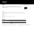
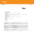
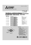
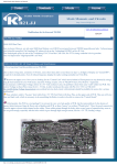
KB2LJJ Radio Mods Database
KB2LJJ
www.r6-ru4montesecchieta.it
IZ5CCV
Home
Radio Mods Database and Manuals
ICOM IC-M600
EXPANDED RF / LSB ACCESS
1- Remove power and antenna.
2- Open the radio.
3- Locate LOGIC unit board.
4- Locate and CUT diode D-8
5- Locate and rmove diode D-15
6- Reassemble the radio.
LSB MODE
1- Press and hold [MODE] buttom and turn power ON.
2- Select LSB mode with mode button.
3- Press [RX] buttom.
4- Press [ tx] buttom.
5- turn radio OFF.
From Paul KC2FXG
This modification come from ICOM
http://www.kb2ljj.com/data/icom/ic-m600.htm (1 di 6)20/08/2009 23.20.41
KB2LJJ Radio Mods Database
IC-M600 PLL problem
http://www.kb2ljj.com/data/icom/ic-m600.htm (2 di 6)20/08/2009 23.20.41
KB2LJJ Radio Mods Database
It is a long time since I repaired the last M600 with this problem but it was the same on the 3 that I have done.
The symptoms are that there is either no AF or that the AF in RX mode fades out after a period of say 20 minutes. There is
obviousely no TX while the PLL circuit has gone unstable.
The reason is that the two halves of the PLL circuit measure against each other producing an offset, this voltage is applied
to the osc, to lock the freq. Icom have poured wax into the entire PLL board. This wax has entered one or more of the
inductors and needs to be removed.
Locate the PLL board from the top of the radio, it is in the middle chassis, the last one you can get to. The PLL circuit
resides in an RF screened enclosure.
Desolder the lid of the enclosure and you will find two sets of identical circuits back to back. Invert the entire radio and
play soldering iron or a flame at safe distance to melt wax out of the trimmers.
Test the radio (remember there will be no AF if the MIC is disconnected) and use an insulated tweaker to bring the pair
stable by trimming either inductor. This last step is usually not required. The amount of wax coming out is usually about
1.5 cc.
Comments on the Icom M600, PLL fix, and how to add an Accessory Jack
(thanks to Dave Kerr for contributing this application note)
Here is some info on the M600 as a result of my perusal of the schematics plus extensive
bench and ship testing:
a. The ICOM M600 can be used at full power on SailMail. It has a thick diecast aluminum rear
chassis with a good heatsink. Thermal switches on the output transistors control a fan on the
heatsink. Make sure that the thin Aluminum cover over the heatsink/fan is not bent as even a
small deformation can stop the fan blades from turning and the M600 could prematurely go into
low power mode.
b. The fan turns on once the output transistors reach 50deg Celsius. At 90deg Celsius, the fan
goes to a higher speed and the ALC logic is invoked to reduce output power to 25 watts.
Transmitting digital data (FSK) at close to full power, continuously for a little over
30minutes on a 30deg Celsius day will bring the output transistors to 90deg and drop the power output (90 is
not a temperature that will cause damage to the transistors). SailMail sessions should
definitely be shorter than 30minutes!
c. In practice, 60 watts PEP is usually more than enough power and will save your batteries,
except when HF conditions are really poor. For 2 years, I have used out M600 on full power for
Seamail and then SailMail, with the only problem being the PLL issue (see below). Once I took
the action described, there were never any problems.
d. The ICOM M600 has had very few reported problems in its lifetime. People have thought that
it can overheat by being used at maximum output with digital data, however I believe this is
actually a different but known problem whereby a trimmer capacitor (C238) in the PLL (Phase
Locked Loop) is temperature sensitive. When the M600 gets hot, the trimmer drifts enough so
that the PLL stops working and the radio will neither receive or transmit until it cools down.
The ICOM America fix is to replace the trimmer with a ceramic one AND reduce the PLL voltage
from the 2.6V in the service manual to 2.0 to give more margin for error. Changing the
capacitor is actually difficult and precise work; a compromise is to leave the capacitor in
situ and adjust the PLL voltage to 2.0V rather than 2.6, with the radio at about 80degF. I
have found that the radio then performs flawlessly across a wide ambient temperature range and
the transmitter can be heavily worked (causing the radio to get quite warm) with no PLL
problems.
http://www.kb2ljj.com/data/icom/ic-m600.htm (3 di 6)20/08/2009 23.20.41
KB2LJJ Radio Mods Database
A competent radio technician should be able to add the appropriate Accessory-1 socket for an ICOM IC-M600 or you can do it yourself if
you are experienced with electronics.
The M600 can be equipped with up to two accessory cables, ACC1 and ACC2. The holes are already on the rear diecast chassis of the
unit, blanked off with blanking plugs. Only ACC1 is required for SailMail. In each case, a multicore, shielded cable is added with an
appropriate in-line, female, standard DIN socket on the end of the cable (which should be about 8inches long). ACC1 is an 8 pin DIN and
ACC2 is a 7 pin DIN. Only ACC1 will be described here. Make sure you use a cable clamp with seal and anti-chafe protection when
installing the cable. You may need to slightly grind the flats of a standard clamp to fit the recess in the chassis.
Pin connections, looking into the female DIN socket with the key upwards:
(key)
7
6
8
3
1
5
4
2
Pin #
Name
Description
1
SCAN
Scan control from ext equipment (not needed for PTC)
2
GND
Connected to chassis ground
3
SEND
Transmits when grounded
4
MOD
Modulation input from ext equipment
5
AF
Fixed AF output regardless of volume
6
SQLS
Squelch out. 0V when squelch open (not needed for PTC)
7
13.6V
13.6V output
8
ALC
Sets power output (not needed for PTC)
Take the cover off the radio by removing the dozen screws from the rear. Turn the radio over and remove the flat screening plate- this
exposes the Main PCB. There is an 8 pin inline socket 2" in from the right hand side, middle of the board, color white. This was designed
for the ACC1 cable. Ideally, obtain a connector to fit into this socket and wire the ACC1 cable wires to this plug per the following table. If
you are desperate, you can carefully solder the wires to the underside of the board after removing the posts that hold the PCB in place.
This will decrease the re-salability of your radio somewhat! It is far preferable to obtain a suitable plug. Connect the screen of the cable to
the chassis ground, inside the rear of the M600. Do not extend the cable screen through to the Main PCB. Take the 8 wires through a
suitably sized ferrite bead (for MF/HF frequencies) and connect them to the ACC1 plug as follows (Pin 1 of the ACC1 plug/socket is
towards the front of the M600 Main board) and they go 1-8 towards the rear:
DIN pin ACC1 pin
1
5
2
6
http://www.kb2ljj.com/data/icom/ic-m600.htm (4 di 6)20/08/2009 23.20.41
KB2LJJ Radio Mods Database
3
4
4
3
5
1
6
2
7
8
8
7
Note: People sometimes fit a voltage divider (2 small resistors) in the DIN at the radio end of the cable from the PTC to the radio (any
ICOM) so that you can run the PTC at a higher output voltage and have a relatively low impedance close to the rear of the radio.
Allegedly this improves the noise immunity. I use such a divider and have had no problems but probably would not have had any issues
anyway as the PTC output impedance is low & the cabling relatively short. Input impedance of the MOD input is about 600ohms.
Dave Kerr
Feb 05 2002
S-Meter
The green lead from j13 + on s-meter. The minus on s-meter tol ground on IC-M600.
Use at potensiometer to adjust the s9.
http://www.kb2ljj.com/data/icom/ic-m600.htm (5 di 6)20/08/2009 23.20.41
KB2LJJ Radio Mods Database
For more information contact OZ7NE/OZ1CYS
http://www.kb2ljj.com/data/icom/ic-m600.htm (6 di 6)20/08/2009 23.20.41