1
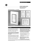
2008-2010 KTM RC8
2009-2010 RC8 R
Z-Fi TC / Z-FI QS INSTALLATION INSTRUCTIONS
P/Ns S542S, S542R, T542S, T542R
WARNING!
USE ONLY IN RACE OR OTHER CLOSED COURSE APPLICATIONS AND NEVER ON PUBLIC ROADS
Z-Fi products do not meet California CARB highway requirements
Z-Fi TC/QS CONTROL UNIT
FUEL HARNESS
COIL HARNESS
SHIFT SWITCH & 30MM SHIFT ROD
DOWNLOAD Z-Fi MAPPER SOFTWARE & ITS INSTRUCTIONS FROM WEBSITE
O2 ELIMINATORS (2)
SPEED SENSOR / BRACKET ASSEMBLY
ASSORTED CABLE TIES
USB CABLE
SWINGARM STICKERS
5
8
6
7
2
1
(1) MAP SELECT
(2) ZAFM CONNECTOR
(3) SWITCHED POWER (RED TAG)
(4) INJECTOR/ THROTTLE
POSITION CONNECTORS
(5) SPEED SENSOR
(6) CRANK POSITION SENSOR
(7) GROUND LUG
(8) NEUTRAL DETECT
4
3
Read through all instructions before beginning installation. This is not a replacement for the ECU.
This document is intended for use by qualified technicians. For more specific stock component identification and
location information refer to a factory service manual.
15330 Fairfield Ranch Rd, Unit E, Chino Hills, CA 91709 (909)597-8300 Fax (909)597-5580 www.Bazzaz.net
WE STRONGLY SUGGEST THAT AN EXPERIENCED TECHNICIAN
INSTALL THIS BAZZAZ PRODUCT
1. Begin the installation by removing the seat, fuel tank, upper & lower front fairings on both sides, and the air inlet
ducts. Take the portion of Bazzaz harness containing the crank position, speed, neutral sensor connectors and route
it through the frame in front of the air box to the left side of the bike.
2. Locate the crank position sensor connectors on the factory harness, which are blue in color and can be found near
the left air inlet opening of the air box (Photo 1). Disconnect the factory connectors and install the mating Bazzaz
crank position connectors inline. (Photo 2)
Bazzaz CKPS
connectors
Factory CKPS
connector
Factory CKPS
connectors
Photo 1
Photo 2
3. Continue to route this portion of the harness toward the rear of the air box, inside the frame. Locate the factory neutral sensor connectors found between the frame and rear cylinder (photo 3). Disconnect the factory connectors and
install the mating Bazzaz neutral sensor connectors inline. (Photo 4)
Bazzaz
Speed
connector
Bazzaz
Neutral connectors
Factory
Neutral
connector
Factory
Neutral
connectors
Photo 3
Photo 4
The Bazzaz harness will have one remaining connector near the neutral connection made in the previous step. This
connector is where the speed sensor provided with the Bazzaz kit connects once it is installed to the motorcycle’s rear
brake caliper mounting bracket. (Photo 3)
4.The factory rear brake caliper mounting bracket has been manufactured by KTM with the option for a rear wheel
speed sensor. It has two pre-drilled holes, providing an opening for sensor placement and securing of the sensor in
place. Note: The speed sensor provided with your kit requires that it be mounted allowing for a particular positioning
in relation to the rear brake disc mounting bolts which the sensor uses to calculate wheel speed. The sensor and
bracket assembly has been pre-assembled to achieve an exact tolerance. Do not attempt to modify the assembly as it
may result in poor performance or even damage to the Bazzaz product and motorcycle.
Insert the assembly into the pre-drilled opening of the caliper mounting bracket and secure it with the supplied 6mm
bolt using a 5mm Allen tool (photos 5 & 6). Route the sensor cable along the underside of the swingarm. Secure it to
the brake line with the supplied cable ties (photos 7 & 8). Continue to route the cable behind the right rear set, up
along the frame, under the fuel tank to the mating connector on the Bazzaz harness on the left side of the motorcycle.
(Photos 9, 10 & 11)
6mm Bolt
Sensor set nut (not
to be adjusted)
Photo 5
Front View
Rear View
Photo 6
Speed Sensor Cable Routing Photos
Cable tie
Cable tie
Photo 7
Photo 8
Speed Sensor Cable Routing Photos continued….
Cable tie
Cable tie
Photo 10
Photo 9
Bazzaz harness
speed connector
Speed sensor
connector
Photo 11
5.On the right side of the motorcycle, locate the factory multi-function 16 pin connector, which is gray in color and
found near the front cylinder (photo 12) Disconnect the factory connectors and install the mating Bazzaz throttle position & injector connectors inline. (Photo 13)
Factory
connectors
Factory 16
pin connector
Photo 12
Bazzaz TPS/
injector connectors
Photo 13
6.Above the factory 16 pin multi-function connector you will find a chassis ground location on the frame. Remove the
factory bolt, install the Bazzaz harness ground lug then reinstall the factory bolt (see Factory service manual for torque
specs). (Photo 14)
Attach Bazzaz
ground lug here
Photo 14
7. Near the factory ECU there is a black four pin connector with a dummy plug inserted into it on the factory harness.
Remove the dummy plug and connect the mating Bazzaz power connector into this factory connector and insert the
dummy plug into the remaining mating Bazzaz power connector. (Photos 15 & 16)
Bazzaz
power
connectors
Dummy plug
Factory
connector
Factory
connector
Photo 15
Factory cap
Photo 16
Prior to reinstalling the right side air inlet duct, route the remainder of the Bazzaz harness containing the control module connector toward the front of the motorcycle into the nose fairing (photo 17). Connect mating Bazzaz harness connectors to the control unit. Reinstall the right air inlet duct and secure the Bazzaz control module to the front of the air
duct using the Velcro strips and long cable ties provided with the kit. (Photo 18)
Cable tie
Photo 18
Photo 17
The KTM RC8 is equipped with an O2 sensor for each cylinder. To achieve maximum performance for racing purposes and to maintain accurate fuel delivery using the Bazzaz control module, the two factory sensors must be bypassed using the O2 eliminators provided with the kit. For each cylinder, locate the sensor and disconnect it from the
factory harness. Secure the sensor cable away from any moving or hot components as it will no longer be used. Connect the Bazzaz O2 eliminator to the mating connector on the factory harness. (Photos 19 & 20)
Unplugged
Sensor
connector
Factory harness
connector
Factory harness
connector
Bazzaz O2
eliminator
Bazzaz O2
eliminator
Unplugged
Sensor
connector
Front Cylinder
Photo 19
Photo 20
8. Now that the installation of the fuel harness is complete, route the Bazzaz coil harness in front of the air box
(similar to that of the Bazzaz fuel harness). Remove the factory harness connector from the ignition coil of the front
cylinder and connect the mating Bazzaz harness coil connectors inline (photo 21). Continue to route the remainder of
the Bazzaz coil harness on the left side of the motorcycle along the inside of the frame. Once again disconnect the factory harness from the ignition coil for the rear cylinder and connect the mating Bazzaz coil connector inline. (Photo
22)
1
2
Coil Harness:
(1) TC adjust switch connection (n/a for Z-Fi QS)
(2) Shift switch connection
(3) Coil Cylinder #1 (Front)
(4) Coil Cylinder #2 (Rear)
4
3
Rear cylinder
coil
Bazzaz coil
harness
Front cylinder
coil
Rear harness
coil connector
Photo 21
Photo 22
Prior to installing the Bazzaz shift switch, apply a small amount of medium strength thread locking agent to the
threads of the 30mm Bazzaz rod supplied with the kit. Using a 3mm Allen tool screw the rod into the female shift
switch housing opening. Install the rod completing into the housing until it no longer turns (photo 23). Remove the
factory shift rod and place one of the nuts from the factory rod and screw it onto the Bazzaz rod. Install the Bazzaz
shift switch and rod assembly in place of the factory shift rod (photo 24). Route the remaining shift switch cable up
the left side of the engine under the fuel tank and connect it with the mating shift switch connector on the Bazzaz coil
harness. This kit is designed for use with stock rear sets, if you motorcycle is equipped with aftermarket rear sets and
requires a different style of shift rod, Bazzaz shift rods of various lengths and configurations which can be viewed at
Bazzaz.net.
30mm Shift Rod
Apply thread locking agent here
Photo 23
Photo 24
9. Reinstall fuel tank and start bike to verify proper installation and system functionality. If any problem is found,
please carefully follow through the installation steps again. If problem still persists, please call Bazzaz tech support
department at (909) 597-8300. After it is determined that everything is correct reinstall the components removed in
step 1.
The Bazzaz Z-Fi controller is capable of storing two maps. These maps can be selected through the use of a
map select switch which can be mounted on the handlebar for easy access and can be purchased separately. Or
these maps can be selected by connecting or disconnecting the map select jumper supplied with kit. When the
map select jumper is connected the control unit is operating using Map 1 which is the map for the RC8.
When the map select jumper is disconnected the control unit is operating using Map 2 which is the map for
the RC8R.
Map 1
Map 2
* To create the ideal map(s) we recommend using the optional Z-AFM self-tuning module. *