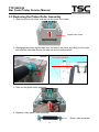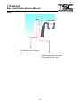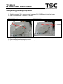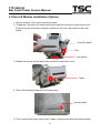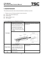
1
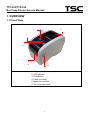
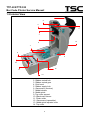
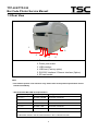
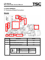
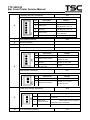
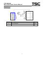
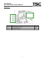
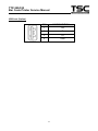
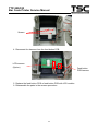
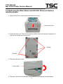
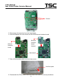
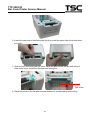
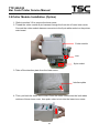
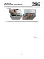
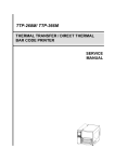
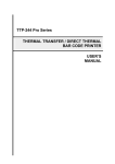
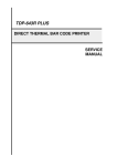
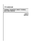
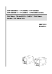
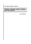
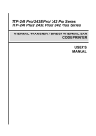
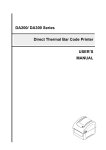
TTP-225 / TTP-323 Series THERMAL TRANSFER / DIRECT THERMAL BAR CODE PRINTER SERVICE MANUAL TTP-225/TTP-323 Bar Code Printer Service Manual TABLE OF CONTENT 1. OVERVIEW ................................................................................................................ 1 1.1 Front View ............................................................................................................... 1 1.2 Interior View ............................................................................................................ 2 1.3 Rear View ................................................................................................................. 3 2. ELECTRONICS.......................................................................................................... 5 2.1 Summary of Board Connectors ............................................................................. 5 2.2 Pin Configuration .................................................................................................. 10 3. MECHANISM ........................................................................................................... 12 3.1 Replacing Feed Button PCB/ Feed Button PCB with LCD Module (Factory option) ......................................................................................................................... 12 3.2 Replacing the Main Board and RS-232/ Ethernet (Option) interface board ..... 14 3.3 Replacing the Platen Roller Assembly ................................................................ 17 3.4 Replacing the Print Head Assembly.................................................................... 19 3.5 Replacing the Stepping Motor ............................................................................. 20 3.7Peel-off Module Installation (Option) ................................................................... 21 3.8Cutter Module Installation (Option) ...................................................................... 23 4. TROUBLESHOOTING ............................................................................................. 25 4.1 LED Status ............................................................................................................. 25 4.2 Print Quality .......................................................................................................... 26 4.3 LCD display (Factory option) ............................................................................... 28 5. MAINTENANCE ....................................................................................................... 29 UPDATE HISTORY ...................................................................................................... 31 i TTP-225/TTP-323 Bar Code Printer Service Manual 1. OVERVIEW 1.1 Front View 5 1 2 3 4 6 1. LCD display (Factory option) 2. LED indicator 3. Feed button 4. Paper exit chute 5. Media view window 6. Top cover open lever 1 TTP-225/TTP-323 Bar Code Printer Service Manual 1.2 Interior View 1 2 3 4 5 14 6 7 8 9 10 12 11 13 1. Ribbon access cover 2. Ribbon rewind hub 3. Ribbon rewind gear 4. Print head 5. Ribbon supply hub 6. Gap sensor (receiver) 7. Media holders 8. Media guide 9. Top cover support 10. Black mark sensor 11. Platen roller 12. Gap sensor (transmitter) 13. Media guide adjuster knob 14. Top cover 2 TTP-225/TTP-323 Bar Code Printer Service Manual 1.3 Rear View 1 6 2 3 5 4 1. Power switch 2. Power jack socket 3. USB interface 4. USB host (Factory option) 5. RS-232C interface / Ethernet interface (Option) 6. SD card socket Note: * The interface picture is for reference only. Please refer to the product specification for the interface availability. * Recommended MicroSD card specification. SD card spec SD card capacity Approved SD card manufacturer V1.0, V1.1 MicroSD 128 MB Transcend, Panasonic V1.0, V1.1 MicroSD 256 MB Transcend, Panasonic V1.0, V1.1 MicroSD 512 MB Transcend, Panasonic V1.0, V1.1 MicroSD 1 GB Transcend, Panasonic V2.0 SDHC CLASS 6 MicroSD 4 GB Transcend - The DOS FAT file system is supported for the SD card. - Folders/files stored in the SD card should be in the 8.3 filename format 3 TTP-225/323 Bar Code Printer Service Manual 2. ELECTRONICS 2.1 Summary of Board Connectors Main board 13 4 3 14 11 2 6 10 1 12 9 Connector 8 5 7 Description Remark 1 USB connector JP56 2 RS-232 interface board connector JP50 Gap sensor receiver connector JP34 Pin 3 Description Voltage 1 Power 3.3V 2 GAP sensor receiver AD 0~3.3V 5 TTP-225/323 Bar Code Printer Service Manual Feed key and LED connector Pin 4 JP28 Description 1 Power 2 LED green 3 LED red 4 Feed switch 5 GND Voltage 3.3V LED light on: 1.1~1.4V LED light off: 1.6~1.9V LED light on: 1.4~1.7V LED light off: 1.8~2.1V 0V: Push key 3.3V: Stand-by 0V 5 Print head connector 6 Micro processor 7 Stepping motor connector JP14 Black mark sensor connector JP17 JP55 Pin Description 1 Power 2 Gap sensor emitter 4 8 3.3V Black mark sensor emitter Black mark sensor receiver AD 3 Voltage Emitter on : 2.1~2.3V Emitter off: 3.3V Emitter on : 2.1~2.3V Emitter off: 2.6~2.8V 0~3.3V Gap emitter connector JP71 Pin Description 1 Power 3.3V 2 Gap sensor emitter Emitter on : 2.1~2.3V Emitter off: 3.3V Head open sensor connector Pin 9 10 Voltage JP16 Description 1 Power 2 Head open sensor receiver 3 GND Voltage 0V to 1.2V to 0V, 10ms square wave continued Head close: 3.3V to under 1.0V to 3.3V, 10ms square wave continued Head open: 3.3V continued 0V LCD connector (Option) JP1 6 TTP-225/323 Bar Code Printer Service Manual Peel-off sensor connector JP19 Pin 11 Description Voltage 1 Power 3.3V 2 Reserved 3 Peel sensor emitter Emitter on: 2.1~2.3V Emitter off: 2.6~2.8V 4 Peel sensor receiver AD 0~3.3V 5 GND 0V Cutter connector JP35 Pin Description 1 Cutter power 24V 2 GND 0V 3 Cutter direction 4 Cutter enable 5 Cutter position sensor switch 0V: Cutter positive cut 5V: Cutter negative cut 0V: Cutter work 5V: Cutter stop 0V: Cutter stop 3.3V: Cutter work 6 GND 0V 7 Logic power 5V 8 Reserved 12 13 microSD socket JP2 Ribbon near end sensor connector JP20 Pin 14 Voltage Description Voltage 1 Power 3.3V 2 Ribbon near end sensor receive on:0V off:3.3V 3 GND 0V 7 TTP-225/323 Bar Code Printer Service Manual Standard board 2 1 Connector Description Remark 1 RS232 connector JP5 2 Main board connector JP50 8 TTP-225/323 Bar Code Printer Service Manual Option board 1 2 Connector Description Remark 1 Ethernet connector/ RJ-45 JP4 2 Main board connector JP50 9 TTP-225/323 Bar Code Printer Service Manual 2.2 Pin Configuration RS-232 PIN CONFIGURATION 1 +5 V 2 TXD 3 RXD 4 CTS 5 GND 6 RTS 7 N/C 8 RTS 9 N/C USB PIN CONFIGURATION 1 N/C 2 D- 3 D+ 4 GND Ethernet (Option) PIN CONFIGURATION 1 Tx+ 2 Tx- 3 Rx+ 4 N/C 5 N/C 6 Rx- 7 N/C 8 N/C 10 TTP-225/323 Bar Code Printer Service Manual USB host (Option) PIN CONFIGURATION 1 +5V 2 D- 3 D+ 4 GND 11 TTP-225/323 Bar Code Printer Service Manual 3. MECHANISM Please turn off the power switch and unplug the power adapter before replacing parts. 3.1 Replacing Feed Button PCB/ Feed Button PCB with LCD Module (Factory option) 1. Open the printer top cover by pulling the tabs located on each side towards the front of the printer, and then lift the top cover to the maximum open angle. 2. Use the screwdriver to remove the 6 screws from the top inner cover. Screws Screws 3. Remove three screws from the feed button PCB holder. 12 TTP-225/323 Bar Code Printer Service Manual Screws 4. Disconnect the harness from the feed button PCB. LCD harness (Option) Feed button PCB harness 5. Replace the feed button PCB or feed button PCB with LCD module. 6. Reassemble the parts in the reverse procedure. 13 TTP-225/323 Bar Code Printer Service Manual 3.2 Replacing the Main Board and RS-232/ Ethernet (Option) interface board 1. Open the top cover and remove the lower front cover. Lower front cover 2. Close the top cover. Then turn the printer upside down and use the screwdriver to remove six screws from lower cover. Screws Screws 3. Remove the lower cover. Lower cover 4. Remove 3 screws from the main board and RS-232/Ethernet interface board. 14 TTP-225/323 Bar Code Printer Service Manual Screws 5. Disconnect all connectors from the main board. 6. Remove/Replace the main board and RS-232/Ethernet interface board. Ethernet Interface RS-232 Interface board board (Option) Main board 7. Take off the interface plate from the lower cover. Interface plate 8. Reassemble the PCB, lower cover and lower front cover in reverse procedures. 15 TTP-225/323 Bar Code Printer Service Manual 9. Insert the lower side of Ethernet interface plate first then push the upper side of interface plate to install it. Ethernet interface plate PUSH 16 TTP-225/323 Bar Code Printer Service Manual 3.3 Replacing the Platen Roller Assembly 1. Open the printer top cover and remove the lower front cover. Lower front cover 2. Disengage the platen holder tabs from the lower inner cover by pulling out the right side and left side tabs. Rotate the tabs into a horizontal position. Unhook Horizontal position 3. Take out the platen roller assembly. 4. Replace a new platen roller assembly. Platen roller assembly 17 TTP-225/323 Bar Code Printer Service Manual Note: The tab here is for regular label. The tab here is for thick label. (Thickness is 0.19 mm) 18 TTP-225/323 Bar Code Printer Service Manual 3.4 Replacing the Print Head Assembly 1. Open the printer top cover. 2. Remove the print head cable cover. 3. Press left concave of the print head bracket then pick up the print head assembly. 4. Disconnect the print head harness. Replace the print head assembly. Print head assembly 4. Reassemble the parts in the reverse procedures. 19 TTP-225/323 Bar Code Printer Service Manual 3.5 Replacing the Stepping Motor 1. Refer to section 3.2 to remove main board and RS-232/Ethernet interface board. 2. Use the screwdriver to remove 2 screws. TTP-225 (203 dpi) TTP-323 (300 dpi) Screws Screws 3. Remove/Replace the stepping motor. 4. Reassemble the parts in the reverse procedures. 20 TTP-225/323 Bar Code Printer Service Manual 3.7Peel-off Module Installation (Option) 1. Refer to section 3.2 to remove the lower cover. 2. Thread the 5-pin peel-off module harness through the front slot of lower inner cover. Plug in the peel-off module harness connector to the 5-pin red socket on the main board. Peel-off module Slot 5-pin socket 3. Embed the tenons into the both sides mortise of lower inner cover. Tenon 4. Take off the interface plate from the lower cover. Interface plate 5. Then, put back the lower inner cover. Fasten 4 screws and Insert the interface plate. 21 TTP-225/323 Bar Code Printer Service Manual 6. Insert the lower side of interface plate first then push the upper side of interface plate to install it. PUSH 7. Open the top cover and peel-off cover. Install the peel-off bar into the both slots of lower inner cover. Install the right side with spring first. Peel-off bar 8. Place the printer in the flat and secured desktop for media loading and printing. 22 TTP-225/323 Bar Code Printer Service Manual 3.8Cutter Module Installation (Option) 1. Refer to section 3.2 to remove the lower cover. 2. Thread the cutter module 8-pin harness through the front slot of lower inner cover. Connect the cutter module harness connector to the 8-pin white socket on the printer main board. Cutter module Slot 8-pin socket 3. Take off the interface plate from the lower cover. Interface plate 4. Then, put back the lower inner cover. Place the cutter module into the both sides notches of lower inner cover, then push cutter to lock into the lower inner cover. 23 TTP-225/323 Bar Code Printer Service Manual 5. Insert the lower side of interface plate first then push the upper side of interface plate to install it. PUSH 6. Place the printer in the flat and secured desktop for media loading and printing. P/N: 39-0000180-00LF 24 TTP-225/323 Bar Code Printer Service Manual 4. TROUBLESHOOTING The following guide lists the most common problems that might be encountered when operating this bar code printer. If the printer still does not function after all suggested solutions have been invoked, please contact the Customer Service Department of your purchased reseller or distributor for assistance. 4.1 LED Status This section lists the common problems that according to the LED status and other problems you may encounter when operating the printer. Also, it provides solutions. LED Status / Color OFF Printer Status No response Possible Cause No power Recovery Procedure * Turn on the power switch. * Check if the green LED is lit on power supply. If it is not lit on, power supply is broken. * Check both power connections from the power cord to the power supply and from the power supply to the printer power jack if they are connected securely. Solid Green ON The printer is ready to * No action necessary. use Green with Pause The printer is paused * Press the FEED button to resume for printing. blinking Red with blinking Error The out of label or 1. Out of label or ribbon ribbon or the printer * Load a roll of label and follow the instructions in setting is not correct loading the media then press the FEED button to resume for printing. * Load a roll of ribbon and follow the instructions in loading the ribbon then press the FEED button to resume for printing. 2. Printer setting is not correct * Initialize the printer by instructions in “Power on Utility” or “Diagnostic Tool”. Note: Printer status can be easily shown on the Diagnostic Tool. For more information about the Diagnostic Tool, please refer to the instruction in the software CD disk. 25 TTP-225/323 Bar Code Printer Service Manual 4.2 Print Quality Problem Possible Cause Check if interface cable is well Recovery Procedure Re-connect cable to interface. connected to the interface connector. The serial port cable pin configuration is Please replace the cable with pin to pin Not Printing not pin to pin connected. connected. The serial port setting is not consistent Please reset the serial port setting. between host and printer. The port specified in the Windows driver Select the correct printer port in the is not correct. driver. The Ethernet IP, subnet mask, gateway Configure the IP, subnet mask and is not configured properly. No print on the label Label loaded not correctly. Continuous feeding labels The printer setting may go wrong. gateway. Follow the instructions in loading the media. Please do the initialization and gap/black mark calibration. Gap/black mark sensor sensitivity is not Calibrate the gap/black mark sensor. set properly (sensor sensitivity is not enough) Paper Jam Make sure label size is set properly. Set label size exactly as installed paper in the labeling software or program. Labels may be stuck inside the printer Remove the stuck label. mechanism near the sensor area. Poor Print Quality Top cover is not closed properly. Close the top cover completely and make sure the right side and left side levers are latched properly. Wrong power supply is connected with Check if 24V DC output is supplied by printer. the power supply. Check if supply is loaded correctly. Reload the supply. Check if dust or adhesives are accumulated on the print head. 26 Clean the print head. TTP-225/323 Bar Code Printer Service Manual Check if print density is set properly. Adjust the print density and print speed. Check print head test pattern if head Run printer self-test and check the print element is damaged. head test pattern if there is dot missing in the pattern. 27 TTP-225/323 Bar Code Printer Service Manual 4.3 LCD display (Factory option) This section lists the LCD display messages that you may encounter when operating the printer. Also, it provides solutions. Messages Possible Cause Recovery Procedure Head Open No Paper Paper Jam * The printer top cover is open. * Please close the top cover. * Running out of label. * The label is installed incorrectly. * Gap/black mark sensor is not calibrated. * Supply a new label roll. * Please refer to the steps in user’s manual to reinstall the label roll. * Calibrate the gap/black mark sensor. * Gap/black mark sensor is not set properly. * Make sure label size is set properly. * Labels may be stuck inside the printer mechanism. * Calibrate the gap/black mark sensor. * Set label size correctly. * The space of FLASH/DRAM or MicroSD card is full. * Delete unused files in the FLASH/DRAM or MicroSD card. * Peel function is enabled. Waiting user to take label away to print the next label. * Please take the label away to print the next label if peeler module is installed. * If peeler module is installed and label is been taken away, but the message remains. Please check if the peeler module connector is connected to main board properly. * If peeler module is not installed, please disable the peeler function. * Cutter jam. * There is no cutter installed on the printer. * Cutter or cutter driver circuit board is damaged. * Remove the jammed label. * Make sure the media thickness is equal or less than 0.19mm. * Replace the cutter or cutter driver circuit board. Out of Mem Take Label Cutter Error 28 TTP-225/323 Bar Code Printer Service Manual 5. MAINTENANCE This session presents the clean tools and methods to maintain your printer. 1. Please use one of following material to clean the printer. Cotton swab (Head cleaner pen) Lint-free cloth Vacuum / Blower brush 100% ethanol 2. The cleaning process is described as following Printer Part Method Interval 1. Always turn off the printer Clean the print head when changing a before cleaning the print head. new label roll 2. Allow the print head to cool for a minimum of one minute. 3. Use a cotton swab and 100% ethanol to clean the print head surface. Print Head Platen Roller 1. Turn the power off. 2. Rotate the platen roller and wipe it thoroughly with 100% ethanol and a cotton swab, or lint-free cloth. Tear Bar/Peel Bar Use the lint-free cloth with 100% As needed ethanol to wipe it. 29 Clean the platen roller when changing a new label roll TTP-225/323 Bar Code Printer Service Manual Sensor Compressed air or vacuum Monthly Exterior Wipe it with water-dampened cloth As needed Interior Brush or vacuum As needed Note: Do not touch printer head by hand. If you touch it careless, please use ethanol to clean it. Please use 100% Ethenol. DO NOT use medical alcohol, which may damage the printer head. Regularly clean the print head and supply sensors once change a new ribbon to keep printer performance and extend printer life. The maximum printing ratio per dot line is 15% for this printer. To print the full web black line, the maximum black line height is limited to 40 dots, which is 5mm for 203 DPI resolution printer. 30 TTP-225/323 Bar Code Printer Service Manual UPDATE HISTORY Date Content Editor 2011/1/25 Modify TSC address Camille 2011/3/24 Modify section 2.2, 3.2, 3.7 and 3.8 Camille 2011/4/8 Modify section 2.2 Camille 2011/5/20 Modify section 3.3 Camille 31 TSC Auto ID Technology Co., Ltd. Corporate Headquarters 9F., No.95, Minquan Rd., Xindian Dist., New Taipei City 23141, Taiwan (R.O.C.) TEL: +886-2-2218-6789 FAX: +886-2-2218-5678 Web site: www.tscprinters.com E-mail: [email protected] [email protected] Li Ze Plant No.35, Sec. 2, Ligong 1st Rd., Wujie Township, Yilan County 26841, Taiwan (R.O.C.) TEL: +886-3-990-6677 FAX: +886-3-990-5577