Download S-COMPACT 50/30
Transcript
S-COMPACT 50/30 HOT FOIL-PRINTING SYSTEMS OPERATING INSTRUCTIONS IMPORTANT NOTES Important Notes Operating instructions Description Version S-Compact 50/30 M00201100EN0313 The operating manual is a translation of the original operating instructions. Applicability The present operating instructions apply to the device with the following article number. Device name S-Compact 50/30 Article Number 0.0000.08620 Description S-Compact 50/30 Using this manual First read the Chapter on “Safety Information” before you begin work with the device. The operating manual enables safe working on and with the device. It is essential that you comply with all safety instructions contained therein. Read the complete operating manual before installing and commissioning the device. The operating manual is a part of the device. It has to be stored so that every person that works on and with the device has access to it at all times. The manual must be complete and in an easily readable condition. When the device is passed on, you have to enclose the operating manual. If the operating manual is lost, please ask for a replacement. Information on the current version of the operating manual may be found on our website www.allen.de. The information provided in these Operating Instructions relate to the devices described under “Applicability”. For additional technical information on the device, please refer to the service manual. Copyright The present document and the described devices therein belong to the company Allen Coding GmbH. All rights remain reserved. Reproduction of this document, in full or in part, requires prior explicit and written approval of the company Allen Coding GmbH. ©Copyright 2013 Allen Coding GmbH, all rights reserved. Disclaimer The company Allen Coding GmbH undertakes all measures to ensure that the published document is up to date at the time of publication. However no guarantee may be given that the document is error-free. The Allen Coding GmbH does not accept liability for possible damages that may have been caused by faulty information in this document. The company Allen Coding GmbH reserves the right to change the present document at any time without prior notice and to alter its content in regards to continuous product improvement. Manufacturer Allen Coding GmbH Friedrich-Bergius-Ring 30 D-97076 Würzburg Direct +49 931 250 76 - 0 Fax +49 931 250 76 – 50 Email: [email protected] Website: www.allen.de S-Compact 50/30 M00201100EN0313 3 TABLE OF CONTENTS Table of Contents Important Notes .......................................................................................................................... 3 Table of Contents ........................................................................................................................ 4 1 Product Identification ......................................................................................................... 6 1.1 Characteristic data ..................................................................................................................................................... 6 1.2 Compliant Use ............................................................................................................................................................ 6 1.2.1 Ambient conditions .................................................................................................................................................... 6 1.2.2 Designated use ........................................................................................................................................................... 6 1.2.3 Qualification of personnel.......................................................................................................................................... 7 1.3 Technical data ............................................................................................................................................................ 8 1.3.1 Mechanical data ......................................................................................................................................................... 8 1.3.2 Electrical data ............................................................................................................................................................. 8 1.3.3 Pneumatic Data .......................................................................................................................................................... 8 1.4 Identification of the device ........................................................................................................................................ 9 1.5 Compliance Information .......................................................................................................................................... 10 1.5.1 CE-conformity .......................................................................................................................................................... 10 1.5.2 EMC Compliance Statements ................................................................................................................................... 10 1.5.3 RoHS / WEEE – compliance ...................................................................................................................................... 10 2 Product Specifications....................................................................................................... 11 2.1 General Description ................................................................................................................................................. 11 2.2 Safety Requirements ................................................................................................................................................ 12 2.3 Deliverable Items ..................................................................................................................................................... 12 2.4 Description of device ............................................................................................................................................... 13 2.4.1 Leading Particulars ................................................................................................................................................... 13 2.4.2 Physical Description ................................................................................................................................................. 15 3 Safety Information ............................................................................................................ 22 3.1 Configuration of the safety instructions .................................................................................................................. 22 3.2 Used pictograms ...................................................................................................................................................... 23 3.3 Hazards during compliant use .................................................................................................................................. 23 4 Installation ....................................................................................................................... 24 4.1 Unpacking ................................................................................................................................................................ 24 4.2 Installation ............................................................................................................................................................... 26 5 Startup ............................................................................................................................. 39 5.1 Type holder - Setting-up .......................................................................................................................................... 39 5.2 Typeholder – Fitting and Removal ........................................................................................................................... 40 5.3 Magazine Loading / Unloading Instructions ............................................................................................................ 41 5.4 Power on and Warm up ........................................................................................................................................... 42 4 S-Compact 50/30 M00201100EN0313 TABLE OF CONTENTS 5.5 Air Supply ................................................................................................................................................................. 42 5.6 Power Supply ........................................................................................................................................................... 42 6 Operating ......................................................................................................................... 43 6.1 Controls .................................................................................................................................................................... 43 6.2 Coder Mounting and Adjustment ............................................................................................................................ 44 6.3 Typeholder ............................................................................................................................................................... 44 6.4 Magazine .................................................................................................................................................................. 44 6.5 Foil Index .................................................................................................................................................................. 44 6.6 Backing Pad .............................................................................................................................................................. 45 6.7 Printing Pressure ...................................................................................................................................................... 45 6.8 Temperature Selection and Adjustment .................................................................................................................. 46 6.9 Dwell Adjustment ..................................................................................................................................................... 47 6.10 Foil Economy ............................................................................................................................................................ 48 6.11 Enable Printing ......................................................................................................................................................... 49 6.12 Alarms ...................................................................................................................................................................... 49 6.13 Power Off ................................................................................................................................................................. 50 7 Troubleshooting ............................................................................................................... 51 7.1 Fault Finding Chart ................................................................................................................................................... 52 7.2 Circuit Description .................................................................................................................................................... 54 8 Cleaning and Maintenance ................................................................................................ 62 8.1 Cleaning.................................................................................................................................................................... 62 8.2 Maintenance ............................................................................................................................................................ 64 9 Maintenance .................................................................................................................... 66 9.1 Spare parts ............................................................................................................................................................... 66 9.2 Service address ........................................................................................................................................................ 66 10 Transport and storage ....................................................................................................... 67 10.1 Transport .................................................................................................................................................................. 67 10.2 Storage ..................................................................................................................................................................... 67 11 Disposal ............................................................................................................................ 68 Appendix ................................................................................................................................... 69 EC-Compliance Statement ................................................................................................................................................... 69 Spare parts .......................................................................................................................................................................... 70 S-Compact 50/30 M00201100EN0313 5 PRODUCT IDENTIFICATION 1 Product Identification 1.1 Characteristic data Device name: S-Compact 50/30 Article Number 0.0000.08620 0.0000.08540 0.0000.08705 Print area Print speed Dwell time Ribbon feeder Print temperature switchable range Foil size Foil Run Out warning Max. width of substrate Device / Part S-Compact 50/30 Power Pack Electronic Module [mm] [prints/min] [sec] [mm] [°C] [mm x m] max. 50 x 30 up to 800 0.01 – 1.0 2 – 30 70 - 210 52 x 305 standard no restriction 1.2 Compliant Use 1.2.1 Ambient conditions Device name: S-Compact 50/30 Ambient temperature, operation Relative humidity, operation (non-condensing) Protection class Ambient temperature, transport and storage Relative humidity, transport and storage (non-condensing) [°C] [%] [IP] [°C] [%] 5 - 40 20 - 85 40 -10 - 70 20 - 85 1.2.2 Designated use The Printing systems can be operated in intermittent mode. The Printing systems are intended for commercial or industrial use. The Printing systems may not be used outdoors or in a non-explosion-safe environment (Ex-area). Only materials suitable for the printing method may be used for printing. The Printing System must be permanently installed into a frame designed for this purpose (machine frame/machinery holder). No modifications to the Printing System are allowed. The applicable safety requirements, the ambient conditions and technical data specified in these Instructions must be observed at all times. Operation of the Printing System may only proceed with the specified accessories/consumable material/replacement parts. Only use original accessories and original replacement parts. Operation/use of the Printing System other than in compliance with the conditions established by the manufacturer may result in hazards to personnel and/or property damage. Potential misuse of the device: 6 The coder should not be operated with this guard removed. The coder should not be operated with the magazine removed. S-Compact 50/30 M00201100EN0313 PRODUCT IDENTIFICATION 1.2.3 Qualification of personnel Operation and set-up: Operation and set-up of the device may only be performed by sufficiently qualified and trained personnel that have been authorized by operator to perform these tasks. Installation, cleaning and maintenance: Installation, cleaning and maintenance of the device may only be performed by fully qualified and trained technical personnel. Maintenance: Maintenance of the device may only be performed by the manufacturer’s technical personnel or by fully trained and qualified technical personnel. S-Compact 50/30 M00201100EN0313 7 PRODUCT IDENTIFICATION 1.3 Technical data This Section contains information on the mechanical and electrical properties of the Printing System and its accessories. 1.3.1 Mechanical data Device name: S-Compact 50/30 Equipment height Equipment width Equipment depth Weight Noise Emission [mm] [mm] [mm] [kg] [dB (A)] Power Pack 107 152 149 2,4 --- Electronic Module 88 196 86 1,3 --- Printhead 215 195 142 6 74 1.3.2 Electrical data Device name: S-Compact 50/30 Rated voltage [VAC] Mains frequency [Hz] Power consumption [A] 220-240 or 110-120 50 at 220-240 Vac 60 at 110-120 Vac 0,7A(at 220 – 240Vac) 1,5(at 110 – 120Vac) 1.3.3 Pneumatic Data The unit requires a normal industry supply of clean dry air. The air supply requirement is: Device name Compact 40/25 Air supply 8 [bar] 3 - 6 bar at up to 25.2 Liters / min (31.5cc/cycle, 0.9cfm @ 800/min) S-Compact 50/30 M00201100EN0313 PRODUCT IDENTIFICATION 1.4 Identification of the device Type plate ② ⑦ ① ③ ④ ⑤ ⑥ The nameplate attached to the device contains the following data: ① ② ③ ④ Article number Device type Serial number Year built S-Compact 50/30 M00201100EN0313 ⑤ ⑥ ⑦ ⑧ Electrical data: Voltage, frequency, power Manufacturer CE-identifier 9 PRODUCT IDENTIFICATION 1.5 Compliance Information 1.5.1 CE-conformity NOTE CE-conformity The product’s CE conformance is certified by attachment of the CE symbol to the name plate and by the conformity statement included with the product. A sample of the declaration is found in the Appendix to these Operating Instructions; see “EC-Compliance Statement”. The device meets the requirements of the following European EC-Guidelines: Machine guideline 2006/42/EG EMC guideline 2004/108/EG The low-voltage guideline 2006/95/EC was adhered to in regards to its protection objectives 1.5.2 EMC Compliance Statements European Union (EU) Electromagnetic Compatibility Directive Compliance Statement This product is in conformity with the protection requirements of EU Council Directive 2004/108/EC on the approximation of the laws of the Member States relating to electromagnetic compatibility. 1.5.3 RoHS / WEEE – compliance RoHS The product complies with the relevant provisions of the RoHS Directive for the European Union. WEEE Directive Statement for the European Union WEEE-Reg.-Nr. DE 84410135 In common with all Electronic and Electrical products the product should not be disposed of in household waste. Alternative arrangements may apply in other jurisdictions. 10 S-Compact 50/30 M00201100EN0313 PRODUCT SPECIFICATIONS 2 Product Specifications In this Chapter you will find information on the deliverable items and on the furnishings of the device. 2.1 General Description The Hot Foil Printing Process Hot foil printing is a process in which heated type is pressed firmly against the item to be printed, with stamping foil between, for a set time. To produce a high quality, non-smudging, permanent print the three variable factors; pressure, temperature and time, must be controlled accurately. 3 1 2 3 4 5 4 1 ITEM BEING PRINTED BACKING PAD PRESSURE HEATED TYPE STAMPING FOIL 5 2 The Allen Coding Systems GmbH S-Compact Coder The S-Compact Coder is designed to produce accurate, clear, high quality coding and marking. It incorporates a range of advanced features to ensure that the requirements of speed, flexibility and ease of use are achieved without compromise. The Coder is available in Left-Hand version. The main features of the coder are: Large print area of 50 mm x 30 mm. Variable dual temperature range incorporating thermocouple control. Microprocessor control Digital temperature display. Low temperature interlock for parent machine. Digital dwell control. Low foil warning and foil fault interlock for parent machine. Patented precision index control for the most efficient use of foil. Reliable high speed operation. Consistently high print quality. S-Compact 50/30 M00201100EN0313 11 PRODUCT SPECIFICATIONS 2.2 Safety Requirements NOTE Please always follow the safety instructions. See Chapter „Safety Information“ 2.3 Deliverable Items NOTE Check the deliverable items for completeness and condition. After receipt of the shipment, please check immediately to see whether all items listed on the delivery ticket are included and are undamaged. The manufacturer does not accept liability for deficiencies that have been claimed subsequently. Complain against: Transport damages directly to the shipping service. Deficiencies and/or incompleteness immediately to the manufacturer or your distributor. The following components belong to the standard deliverable items for the device Position Count Article number Specification 001 002 003 1 1 1 0.0000.08620 0.0000.08540 0.0000.08705 S-Compact 50/30 Power Pack S-Compact 50/30 Electronic Module S-Compact 50/30 004 1 3.0000.08564 Air-Service-Unit Position 001 Article Number 0.0000.08620 “S-Compact 50/30” includes the following items: 005 006 007 1 1 1 0.0000.08530 0.G00.08620 100180 Magazine S-Compact 50/30 Printhead S-Compact 50/30 Complementary Set S-Compact 50/30 Position 007 Article number 100180 “Complementary Set S-Compact 50/30” includes the following items: 008 009 010 011 012 013 014 015 016 12 1 1,6m 1,6m 1 1 1 1 1 1 0.0000.01016 0.0000.08635 0.0000.08636 3.0000.46018 3.0000.46019 3.0000.46020 3.0000.46023 A.3055.00200 ------------------- Washer Air Pipe 6-4 black Air Pipe 6-4 blue Spacer 13mm Spacer 17mm Spacer 32mm Adjustable Hand Leaver – M8 x 83mm Hot Foil, Typ 200, black, 305m x 50mm CD with operating instructions S-Compact 50/30 M00201100EN0313 PRODUCT SPECIFICATIONS 2.4 Description of device 2.4.1 Leading Particulars Power Supplies The unit requires a single phase supply which must be connected to the emergency stop circuit of the parent machine. The power supply unit, which should be isolated before making changes, incorporates a simple plug-in link to select for use with mains supplies of either: 220-240 Vac 50Hz or 110V-120Vac 60Hz Fuses Four replaceable fuses are mounted on the printed circuit board in the power supply unit. FS1 Mains input line - T 1.6AL 250 - T 1.6AL 250 FS2/FS3 Control circuit supply - T 500mAL 250 Volt FS4 Heater supply - T 2.5AL 250 Volt Volt (220-240Vac) Volt (110-120Vac) Air Supply The unit requires a normal industry supply of clean dry and oil-free air. The air supply requirement is: 3 - 6 bar at up to 25.2 Liters / min (31.5cc/cycle, 0.9cfm @ 800/min) Operating Temperatures The unit can be switched, before or during operation, between two temperature ranges to suit the application and current operating conditions. The temperature ranges can generally be adjusted between: 70°C - 140°C or 140°C - 210°C (158°F - 284°F or 284°F - 410°F) Adjustment within the ranges is carried out using potentiometers which are concealed to facilitate unauthorized tampering. Range of Typeholders To allow rapid changes of print, and to allow its use in the widest range of applications, the S-Compact Coder has been designed to accept interchangeable typeholders. These can be supplied as a blank, for machining by the end user, or ready machined to suit the four main type categories: Fixed row and universal (for use with cast type) T-slot (for use with T-slot type, engraved brass or hardend steel) Zinco (for etched zinc plates, 5 mm thick) Rotary flick wheel (wheels to allow easy changing of date, price or numbering) For further information contact the Allen Coding GmbH Sales. S-Compact 50/30 M00201100EN0313 13 PRODUCT SPECIFICATIONS Foil - Stock Range The S-compact coder is designed to accept a reel of foil with the following maximum dimensions: Maximum Outside Diameter 96 mm for 305 m magazine Width 50 mm +1.0 mm Core Diameter 25.95 mm +0.2 mm Foil reels supplied by Allen Coding GmbH are specified by their nominal length, quoted in meters. For printing on different materials a variety of grades are recommended by the manufacturers. 14 S-Compact 50/30 M00201100EN0313 PRODUCT SPECIFICATIONS 2.4.2 Physical Description Coder The coder unit comprises a heated block, mounted to the rod of a pneumatic cylinder which, in turn, is supported by a machined frame. This contains the solenoid valve, to actuate the cylinder, the foil indexing mechanism and a printed circuit control and connection board. Power and control signals are connected via a plug connection. Air to the solenoid valve and the exhaust from the cylinder, via the valve, are connected to push-in fittings. Alternative air connections are provided to allow for different installation requirements. The operating mechanism is fully enclosed, with the exception of a rotating shaft which provides motive power to index the foil in the magazine. Foil index depends on the rotation of this shaft and an adjustment knob, to control the index, is provided on top of the coder. 5 6 1 7 8 2 9 3 4 10 11 1 MAGAZINE DRIVE SHAFT 7 2 3 4 5 6 MAGAZINE GUIDE SPIGOT HEATED BLOCK MAGAZINE LATCH PIN FOIL INDEX ADJUSTMENT TEMPERATURE RANGE SELECTOR SWITCH 8 9 10 11 S-Compact 50/30 M00201100EN0313 TEMPERATURE ADJUSTMENT POTENTIOMETERS (UNDER PLATE) LOW FOIL SENSOR MAGAZINE GUIDE SPIGOT MOUNTING HOLE INDENTS FOR LOCATION 15 PRODUCT SPECIFICATIONS Magazine The foil magazine fits onto spigots provided on the coder body and is retained by a simple mechanical catch. The magazine provides a take-up roller, driven from a rubber covered drive roller by an endless belt. The drive roller contains a one-way clutch and is turned by the rotating shaft on the coder body. Foil is pulled by the drive roller via guide pins, from a feed-on spool, the rotation of which is controlled by a friction belt to stop overrun of the foil. Sprung tension rollers are provided immediately after the feed-on spool and between the drive roller and take-up roller. 3 4 1 5 2 2 6 9 7 8 1 2 3 4 5 16 FEED-ON SPOOL FOIL ROLLERS FOIL TENSION SPRING TAKE-UP ROLLER DRIVE BELT 6 7 8 9 DRIVE ROLLER NIP ROLLER GUIDE POST FOIL TENSION ROLLERS S-Compact 50/30 M00201100EN0313 PRODUCT SPECIFICATIONS Electronic Module The electronic module is provided with a mounting bracket which allows its fitting in a position convenient to the user. The unit provides control, indication and warning functions. 1 7 2 8 9 10 11 3 4 5 12 6 1 2 3 4 5 6 7 DWELL INDICATOR ADJUSTMENT BUTTONS SIGNAL DELAY INDICATOR LED DISPLAY TEMPERATURE RANGE INDICATORS LOW TEMPERATURE INDICATOR POWER ON LED S-Compact 50/30 M00201100EN0313 13 8 9 10 11 12 13 PRINT ENABLE TEST PRINT (SINGLE CYCLE) LOW FOIL INDICATOR FOIL FAULT INDICATOR ALARM CANCEL / FAULT INDICATOR SET TEMPERATURE SWITCH 17 PRODUCT SPECIFICATIONS Air Service Unit The air service unit incorporates a pressure regulator and water separation bowl, a pressure gauge, air distribution manifold and an air exhaust silencer. The water separation bowl is fitted with a manual drain valve. 1 2 3 18 WATER SEPARATION BOWL MANUAL DRAIN VALVE PRESSURE CONTROL 4 5 6 PRESSURE GAUGE AIR DISTRIBUTION MANIFOLD EXHAUST AIR SILENCER S-Compact 50/30 M00201100EN0313 PRODUCT SPECIFICATIONS Power pack The power pack is a fully enclosed unit containing a power transformer, fuses and connection blocks to distribute the power and control signals to and from the electronic module and parent machine. 1 1 GLAND FOR MODULE CABLE S-Compact 50/30 M00201100EN0313 19 PRODUCT SPECIFICATIONS Functional Description 1. With Electronic module Power Pack 110/240 V ~ 50/60 Hz Transformer Air-Service-Unit Air 6-10 bar 12 v Electronic Modul Filter Microprocessor Circuit Regulator Low Temp Foil Fault Low Foil Exhaust Air Silencer Audible Alarm 3-6 bar 48 v Restrictor Jets 24 v 24 v dc Print Head Temperature Control Heater Low Temperature Circuit Solenoid Air Valve 24 v dc Air Pulse Air Cylinder Heater Block Tape Index Mechanism Type Holder Foil Fault Low Foil Magazine Tape Index 24 v dc Print 20 S-Compact 50/30 M00201100EN0313 
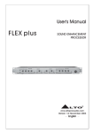
PRODUCT SPECIFICATIONS 2. Without Electronic Module Power Pack 110/240 V ~ 50/60 Hz Transformer Air-Service-Unit Air 6-10 bar 12 v Machine Manufacturer‘s Electronic Modul 24 v Filter Microprocessor Circuit Regulator Low Temp Foil Fault Low Foil Exhaust Silencer Audible Alarm 3-6 bar 48 v Restrictor Jets 24 v dc Print Head Temperature Control Heater Low Temperature Circuit Solenoid Air Valve 24 v dc Air Pulse Air Cylinder Heater Block Tape Index Mechanism Type Holder Foil Fault Low Foil Magazine Tape Index 24 v dc Print S-Compact 50/30 M00201100EN0313 21 SAFETY INFORMATION 3 Safety Information This Chapter contains information on the configuration and relevance of the safety information presented in these operating instructions, and also information on possible hazards which may occur even for compliant usage of the device. 3.1 Configuration of the safety instructions SIGNAL WORD Type and source of hazard Explanation of the hazard and information on possible consequences of non-compliance Activities/prohibited actions to help prevent accidents. The pictogram denotes the type of hazard The safety sign before the signal word indicates a possibility of personal injury The signal word denotes the severity of the hazard SIGNAL WORD Consequences when hazard occurs Probability of occurrence HAZARD Severe physical injury or death (irreversible) imminent WARNING Severe physical injury or death (irreversible) possible CAUTION Slight/minor physical injury (reversible) possible Property damage to machinery and/or to nearby assets possible ATTENTION The reference text describes: type and source of hazard, the possible consequences of disregarding the safety instruction, measures or restraints to prevent the hazard. 22 S-Compact 50/30 M00201100EN0313 SAFETY INFORMATION 3.2 Used pictograms Pictogram Meaning Warning of a general hazard Warning of possible property damages Before performance, observe the corresponding information in the operating manual General note 3.3 Hazards during compliant use CAUTION Potential hazard caused by incorrect accessories and spare parts! The use of accessories and spare parts that are not recommended by the manufacturer may compromise safety, functionality and efficiency of the device. Any liability and warranty for any damages caused by not recommended accessories and spare parts or non-intended use is excluded by the manufacturer. Thus use manufacturer recommended accessories and spare parts exclusively. S-Compact 50/30 M00201100EN0313 23 INSTALLATION 4 Installation In the following Chapter you will find information on the installation of the device. Allen Coding GmbH can provide mountings suitable to install the S-Compact Coder onto a wide range of machines. In the following sections, the standard mounting frame is described. Contact Allen Coding GmbH for assistance or, alternatively, use the dimensions given for the standard mounting frame as a guide. CAUTION Potential hazard due to incorrect or non-compliant installation! An incorrect or improper assembly of the device may impair safety, functionality and efficiency of the device. The installation of the device may be performed exclusively by qualified technical expert personnel. Follow the relevant instructions in the operating manual. The coder, electronic module and power pack must be earthed. Isolate the coder, electronic module and power pack before removing any covers. NOTE Backing Pad A resilient backing pad should be used if printing to a media which would otherwise have a rigid backing, for example, when printing to a label strip. This takes up any small inaccuracies in the type face, reduces shock loading on the coder and gives greatly improved performance and longevity. The use of a backing pad is not required when printing directly onto a more resilient media, for example, card-board boxes. 4.1 Unpacking CAUTION Hazards due to defects or transport damage! Transport damage to the device may result in unforeseeable hazards to personnel and/or property. When unpacking the device, check for any visible damage. Never ever connect a damaged device to the voltage supply. In case of transport damage, consult with the manufacturer or your distributor. NOTE Check the deliverable items for completeness and condition. After receipt of the shipment, please check immediately to see whether all items listed on the delivery ticket are included and are undamaged. The manufacturer does not accept liability for deficiencies that have been claimed subsequently. File complaints with: Transport damages directly to the shipping service. Deficiencies and/or incompleteness immediately to the manufacturer or your distributor. 24 S-Compact 50/30 M00201100EN0313 INSTALLATION NOTE Recycling of transport packing The transport packaging may be stored for later recycling, e.g. transport or storage. Step1: Open the transport packing. Step 2: Check whether all items listed on the delivery slip are included and undamaged. Step 3: Remove all components of the device carefully from the transport packing S-Compact 50/30 M00201100EN0313 25 INSTALLATION 4.2 Installation Space Requirements The illustration shows the installation dimensions of a Left-Hand Coder. When using a mounting frame not supplied by Allen Coding GmbH, then it is suggested that a convenient storage location is provided for the type holder extraction handle. The handle has an M5 thread. 1 5 2 4 3 1 +109 mm FOR REMOVAL OF MAGAZINE 4 2 3 4 LOCATION INDENTS FOR BALL CATCHES TAPPED M8 FOR MOUNTING SCREW 5 205 mm WITH TYPE HOLDER IN FORWARD POSITION 198 mm WITH 305 m MAGAZINE NOTE Clearance required for removal of magazine Observe the clearance required for removal of the magazine and the possibility to turn the unit 360° in steps of 90° (longitudinal and lateral alignment of the type head to the printing medium. 26 S-Compact 50/30 M00201100EN0313 INSTALLATION Mounting Frames The illustration shows the principle dimensions and features of the standard Allen Coding GmbH S-Compact Coder mounting frame (Art.-No.:1.0000.04270) 4 5 1 7 6 2 3 10 9 8 Mit Knebel zur Druckerbefestigung S-Compact 50/30 M00201100EN0313 27 INSTALLATION 1 2 3 4 5 THREADED ROD FOR POSITION ADJUSTMENT LOCKING BOLT POSITION ADJUSTMENT KNOB ADJUSTMENT LOCKING KNOB POSITION INDICATOR 6 DISTANCE TO BACKING PAD 7 8 9 10 BALL CATCHES LOCATE CODER AT 90 INTERVALS STAR KNOB KNURLED ADJSTMENT NUTS BACKING PAD Coder Mounting and Adjustment Instructions The following instructions are based on the use of a standard Allen Coding GmbH mounting frame. Any custom built installation adapter should incorporate at least the alignment adjustments indicated. Arrange to install the mounting frame to provide coder position adjustment to suit the application. For example, if printing directly onto cardboard boxes then it may be desired to allow the height of the printed code up the side of the box to be varied. Alternatively, if printing to label stock, the alignment of the printed text across the face of the label would be more important. Install the mounting frame securely. Mount the coder unit to the frame using an M8 screw. Ensure that the screw length does not allow it to protrude beyond the thickness of the coder mounting plate. Align the coder head using the ball catches and indents provided on the mounting face. Adjust the coder printing position. Release the coder clamping handle by a quarter turn and move the coder position using the position adjustment knob. Retighten the coder clamping handle. Ensure that the chosen method of mounting will allow the face of the printing block to be parallel with the face of the printing medium. If necessary, release two or more of the adjustment locking knobs and turn the knurled adjustment nuts to correct the alignment. Tighten the adjustment locking knobs. HINWEIS Replacement of adjustment locking knobs The adjustment locking knobs may be replaced using standard hexagon nuts to prevent unauthorized tampering. 28 If necessary, insert the backing pad strip and ensure that it is aligned with the print head. Note that the backing pad strip is used to provide a resilient surface to take up small inaccuracies of the type face and will not be necessary if the printing medium is sufficiently resilient, S-Compact 50/30 M00201100EN0313 INSTALLATION Electronic Module Mounting Instructions The illustration shows the electronic module. The module may, within the restrictions of cable length, be mounted in any convenient position in which the operator can clearly see the indicator lights and can access the push-buttons. (Preferably between 0.6 m and 1.9 m from floor level). 1 1 4 MOUNTING HOLES Ø 5,5 S-Compact 50/30 M00201100EN0313 29 INSTALLATION Air Service Unit Mounting and Adjustment The illustration shows the installation dimensions for the standard air service unit, which should be mounted vertically, as shown. Access must be provided to allow maintenance personnel to adjust the operating pressure and view the pressure gauge. Access is also required to visually check the liquid level in the sight glass and to drain the bowl using the manual drain valve. CAUTION Moisture in water separation bowl of air service unit and exhaust discharge of the cylinder. Moisture can accumulate in the water separation bowl and in the exhaust charge of the cylinder and can cause a possible hazard if coming into contact with live electrical circuits. Drain moisture from the water separation bowl at regular intervals Check exhaust charge of the cylinder for moisture and drain if necessary Position the air-service-unit so that there is no chance of this moisture coming in contact with live electrical circuits VIEW A 30 1 8 mm PUSH IN AIR FITTING FOR AIR SUPPLY 2 3 MANUAL DRAIN VALVE 4 MOUNTING HOLES Ø 5,5 4 6 mm PUSH IN AIR FITTINGS FOR PIPES TO PRINTHEAD S-Compact 50/30 M00201100EN0313 INSTALLATION Power Pack Mounting Instructions The illustration shows the installation dimensions for the power pack. Following installation, access to the power pack is required for replacement of fuses as necessary. 2 1 1 CABLE Ø 4 MIN – Ø 8 MAX S-Compact 50/30 M00201100EN0313 2 2 MOUNTING HOLES FOR M5-SCREWS 31 INSTALLATION Electrical Connections 1. With Electronic module (Standard) For identification of terminals and connections in the power supply, refer to diagram below. 32 S-Compact 50/30 M00201100EN0313 INSTALLATION For identification of terminals and connections on the electronic module, refer to diagram below. Electronic Module Connections Printhead PCB Connections S-Compact 50/30 M00201100EN0313 33 INSTALLATION 2. Without Electronic module (OEM version) B FS2 2.5A ye/gr orange blue orange black white/red yellow orange red red yellow yellow A pink FS3 500mA Relay 1: Low temperature Relay 2: Foil end Foil fault white brown black Relay 3: Low foil warning red/brown violet N/C N/O brown 24V DC impulse + COMMON N/C 0V yellow/red 24V red N/O COMMON gr/ye N/C blue N/O brown COMMON set temp. 50mV/C° actual temp. 50mV/C° FS1 1.6A Attention: Art.-No.: 1.0001.08540 to be used only without electronic module. Time-controlled voltage pulse required for terminals 27 and 29. Scope of delivery includes connection cable 0.0001.08977, length 6m. 34 S-Compact 50/30 M00201100EN0313 INSTALLATION Relay 1: Low Temperature 18 N/C 16 COMMON Relay 2: A Foil End / Foil Fault 15 N/C Low Foil Warning Output max. 6A/250V 14 N/O 13 COMMON Relay 3: Ouput max. 6A/250V 17 N/O N/C 12 N/O 11 COMMON 10 Output max. 6A/250V 36 yellow/green B 35 blue 34 black 33 46 white/red 32 pink 45 yellow 31 red/brown 44 orange 30 violet 43 42 brown 29 + 28 27 - 41 time-controlled voltage pulse 24V DC 40 39 26 38 yellow/red 25 37 red 24 23 22 21 S-Compact 50/30 M00201100EN0313 20 set temperature 50mV/C° 19 set temperature 50mV/C° gr/ye PE blue N brown L Mains Input 35 INSTALLATION Pneumatic Connections All pneumatic connections should be made using standard 6 mm x 4 mm flexible air lines, preferably coded to distinguish the infeed to the air cylinder. The connections required between the coder and air service unit are shown in the illustration. NOTE Alternative connections If space limitations for the installation result in a restrictive pipe run to the end of the coder, then alternative connections should be used. 6 5 1 7 2 3 4 1 2 3 4 36 PRINTHEAD AIR INFEED 6 mm O/D PIPE (BLACK) AIR EXHAUST 6 mm O/D PIPE (BLUE) EXHAUST AIR SILENCER 5 6 7 ALTERNATIVE AIR CONNECTIONS VIEW A AIR INTAKE 8 mm O/D PIPE S-Compact 50/30 M00201100EN0313 INSTALLATION Languages & Fault Relays Set-up Before changing the language for warning or temperature messages, disconnect the equipment from the mains supply as the switch positions must be at zero voltage. Unscrew the 4 screws retaining the front panel of the switch cabinet. A 4-switch bracket (SW1) enables the message to be changed as shown in the table below. SWITCH NO. LANGUAGE UNIT TEMPERATURE 1 2 3 4 OFF OFF OFF XXX ENGLISH °C ON OFF OFF XXX GERMAN °C OFF ON OFF XXX FRENCH °C ON ON OFF XXX SWEDISH °C ON ON ON XXX ENGLISH °F OFF OFF ON XXX FINNISH °C The 3 jumper switches, (JS2), allow the user to change the operation of the fault relays. When set between pins 1 & 2 the relays are open and do not change state at power up. When set between pins 2 & 3 the relays are open, but and change their state on power up. JS2 S-Compact 50/30 M00201100EN0313 SW1 37 INSTALLATION Heater Block Set-up The Coder is supplied with the Heater Block configured to accept either 30mm wide Type holders (used by the Compact 205 series) or 35mm wide Type holders (to make use of the 50/30 print area). The configuration for 30mm wide Type holders is shown below: Configuration for 35mm wide Type holders To configure the Heater Block to accept 35mm wide Type holders make the following changes: 1. Ensure the Coder is not connected to the Power and Compressed Air supplies. WARNING Heating block cool down If the coder has recently been in use allow the heater block to cool before continuing 38 2. Remove the Magazine and type holder from the Coder, then remove the Heater Block Guard 3. Carefully remove the clip (1) retaining the long detent (2). 4. Withdraw the long detent (2). 5. Undo and remove the 2 screws (3). 6. Remove the Heater Block Insert (4). 7. Extract the clip and short detent (5). 8. Insert the short detent (5) into the Heater Block in place of the long detent and retain using the clip. S-Compact 50/30 M00201100EN0313 STARTUP 5 Startup 5.1 Type holder - Setting-up WARNING Skin burns due to high temperature of type holder and heater block The heater block and type holder operate at a temperature high enough to cause skin burns if touched. Take care to avoid direct contact when removing or inserting a type holder from the heater block. The four main categories of type holder are prepared in the following manner: Fixed Row and Universal These type holders accept cast type. Clean the recess(es) to ensure that the type will be seated correctly. Insert the type characters and spacers, to create gaps, one piece at a time. Fit additional spacers as necessary to align the type and fill the recess(es). Use the screws in the end of the type holder to clamp the type securely, an hexagonal wrench is provided. T-slot These type holders accept T-slot type which is normally engraved hardened steel. Clean the recess(es) to ensure that the type will slide easily in the slots. Insert the type characters and spacers, to create gaps, one piece at a time. Insert the T-slot type retaining clips or blocks into each end of the slot(s). Zinco These type holders accept a 5 mm thick etched zinc plate. Clean the mating faces to ensure that the plate will be seated correctly. Use the countersunk screws to secure the plate, a hexagonal wrench is provided. S-Compact 50/30 M00201100EN0313 39 STARTUP Rotary Flick Wheel These type holders are supplied with rotary wheels carrying the type characters. Rotate the wheels to obtain the desired print. An indexing pencil is provided to push each wheel round to the correct position. 5.2 Typeholder – Fitting and Removal WARNING Skin burns due to high temperature of type holder and heater block The heater block and type holder operate at a temperature high enough to cause skin burns if touched. Take care to avoid direct contact when removing or inserting a type holder from the heater block. Screw the extraction handle into the tapped hole provided in the type block and use this as a handle. Check that the type face is correctly oriented and slide the type block into the heater block. Take care to avoid direct skin contact with the type holder or heater block. To withdraw the type holder, screw the extractor into the tapped hole and use this as a handle to slide the type block out . With normal care it is possible to extract the block safely without needing to cool it down first. 40 S-Compact 50/30 M00201100EN0313 STARTUP 5.3 Magazine Loading / Unloading Instructions The coder is fitted with a foil fault sensor. An audible alarm will sound and the fault indicator will be illuminated when either the foil runs out at the end of the reel, if the foil breaks, or when a magazine loaded with foil is removed. To cancel the audible alarm, press the alarm cancel button. The button will remain lit until a loaded magazine is replaced on the coder. The coder will not function until the foil is replaced. NOTE Reduction of downtime To reduce down-time, it is recommended that a second, spare, magazine is kept on standby. This can be pre-loaded with foil at a convenient time and rapidly exchanged for an empty magazine. Release the magazine from the coder body by sliding the latch out of engagement with the central pillar. By pulling on the two handles, remove the magazine directly away from the coder body. Fit an empty cardboard core onto the take-up roller, this would normally be transferred from the now empty feed-on spool. Check the condition of the rubber foil drive roller, if necessary, clean off any dust Referring to the label, push a new reel of foil onto the feed-on spool and thread the foil, using the path indicated, to the take-up roller. Secure the free end of the foil to the cardboard core on the take-up roller using adhesive tape. Rotate the foil drive roller to ensure that the foil is securely attached at the take-up roller and to apply the correct initial tension to the foil. NOTE On-way clutch of foil drive The foil drive roller is fitted with a one-way clutch and can only rotate in one direction. Replace the magazine, checking that the foil enters cleanly into the slot provided at the rear of the coder. Guide pins ensure that the magazine is correctly aligned but, if the foil is not passed through this slot the foil run out sensor will still inhibit operation. 1 3 1 2 3 PUSH NEW REEL OF FOIL ONTO FEED-ON SPOOL (MAX. DIA 96 mm) PIGMENT (DULL) SIDE OF FOIL USE EMPTY CARDBOARD CORE ON TAKE-UP REEL 2 Foil Route - 305 m Magazine (Left-Hand) S-Compact 50/30 M00201100EN0313 41 STARTUP 5.4 Power on and Warm up Normal Operation In normal operation the unit will be powered up at some time before the start of the working shift to allow the correct temperature to be reached before operation is due to start. WARNING Skin burns due to high temperature of type holder and heater block The heater block and type holder operate at a temperature high enough to cause skin burns if touched. Take care to avoid direct contact when removing or inserting a type holder from the heater block. At the start of the shift, visually inspect the condition of the coder, coder mounting and wiring. If necessary, clean the unit and the surrounding area. Rectify any apparent signs of damage or wear. Following any maintenance or problems with the unit it is recommended that the following Initial Set-up Procedure is followed in sequence. 5.5 Air Supply Check that an air supply is connected to the air service unit and that the pressure gauge is indicating an outlet pressure of at least 4 bar (58 psi). If necessary, lift the adjusting knob on the regulator and adjust, by turning, until the correct pressure is indicated. Press down on the regulator adjusting knob to lock the adjustment. Drain any moisture that may have accumulated in the bowl. 5.6 Power Supply Enable the power supply to the power pack. The green LED’s on the electronic module and the coder body will be illuminated to indicate that the 24 VDC power supply is enabled. In addition, any alarm LED’s (yellow triangles) will be illuminated on the electronic module. 42 S-Compact 50/30 M00201100EN0313 OPERATING 6 Operating 6.1 Controls When the power has been enabled, the four illuminated push-buttons will light in sequence to show that the microprocessor is powered up. If the coder is not connected to the electronic module, “NO CODER” will be scrolled across the LED display. Before connecting the coder, set the heater selector switch to high or low range as required. Normally, the low range would be used but, for high speed printing or with a large area of print, the high temperature range may be required. Switch off the power supply before connecting the coder, then enable the supply again. With the coder connected, the temperature will be displayed and the appropriate `range’ LED (yellow circle) will be illuminated, (Centigrade or Fahrenheit). The “Low Temperature” LED (triangle) will be illuminated until the operating temperature is reached. If any alarm conditions exist, the relevant LED’s (triangles) will be illuminated and the “Fault Indicator” will flash. The applicable fault message/s, “LOW FOIL”, “FOIL FAULT” or “LOW TEMP” will be scrolled across the LED display, alternating with the display of temperature. The “Fault Indicator” push-button will remain illuminated until all the faults have been cleared. Once the fault conditions have been cleared the display will remain at the temperature. To display the pre-set temperature, used when making an adjustment at the coder, press the “Set Temperature” push-button. This will remain illuminated while the pre-set temperature is being displayed. Press again to return the display to the actual temperature. To change the dwell setting, or to display it, press and release one of the up/down adjustment buttons .Then wait for the “Dwell” LED (yellow circle) to illuminate. Unless the dwell time has been set up or was last being used for the same printing task and has not been disturbed since, set the dwell control to indicate 0035, that is 35 milliseconds. The dwell setting can be adjusted to a maximum of 1 second, (1000 milliseconds), as required. Wait for the display to return to the actual temperature, (approximately 2 seconds after the last adjustment was made), before making any other adjustments. To display the `signal delay’ setting press and hold both of the up/down adjustment buttons then wait for the “Delay” LED (yellow circle) to illuminate. The delay setting can be adjusted to a maximum of 2.5 seconds, (2500 milliseconds), as required. Wait for the display to return to the actual temperature, (approximately 2 seconds after the last adjustment was made), before making any other adjustments. HINWEIS Dwell and delay settings Adjusting the dwell or delay settings down, past zero, will take the setting to maximum and then continue to reduce it. Single steps of adjustment can be achieved by `pecking’ the up or down push-button with a finger. There is a concealed push-button behind the logo which, when pressed and held for approximately 2 seconds, will initiate a test program. First, all of the segments in each of the 4 display digits will be illuminated in sequence, then “SOFTWARE VERSION” will be scrolled across the display. This will then change to show the version number, for example 0002. The display will remain while each of the LED’s controlled by the microprocessor, (not the power LED or the alarm LED’s), are illuminated in sequence. When the test program is complete the controls will return to the status prior to it being initiated, which may cause the alarm to sound. S-Compact 50/30 M00201100EN0313 43 OPERATING 6.2 Coder Mounting and Adjustment If the coder has been set up as described above under Installation, or was last being used for the same printing task and has not been disturbed since, this procedure can be ignored. If the coder mounting has been disturbed, or is being set-up for a new printing task then proceed as follows: Release the four adjustment locking knobs and turn the knurled adjustment nuts by equal amounts to move the coder away from the print position. By turning the adjustment nuts by equal amounts the alignment will be maintained. Tighten the adjustment locking knobs. Adjust the coder printing position. Release the coder clamping handle by a quarter turn and move the coder position using the position adjustment knob to align the print head with the required printing position. Retighten the coder clamping handle. 6.3 Typeholder WARNING Skin burns due to high temperature of type holder and heater block The heater block and type holder operate at a temperature high enough to cause skin burns if touched. Take care to avoid direct contact when removing or inserting a type holder from the heater block. Check and/or set-up the required print set in the type holder. Refer to Section 5.1-5.2. NOTE Quick change of type It is suggested that a spare type holder is obtained. Type can then be set using a cool type holder. Using the extractor handle, load the type holder to the heater block. 6.4 Magazine If necessary, load foil onto the magazine. Locate the magazine onto the coder and secure in place using the latch. Refer to Section - “Magazine Loading / Unloading Instructions” 6.5 Foil Index If the coder foil index has previously been set up or was last being used for the required printing task and has not been disturbed since, this procedure can be ignored. Adjust the foil index knob fully anti-clockwise to give the maximum foil index for each printing cycle. For the most efficient use of foil the index knob must be adjusted in operation. Refer to Section – “Foil Economy” . 44 S-Compact 50/30 M00201100EN0313 OPERATING 6.6 Backing Pad Check that the backing pad is correct for the print task. Check that the backing pad is in good condition and is aligned with the print area. A backing pad is not normally required for carton printing. 6.7 Printing Pressure Allow at least 5 minutes for the print head and heating block to reach and stabilize at the set temperature. The low temperature indication LED on the coder body will extinguish when the correct temperature is reached. Position the material to be printed over the backing pad, press the Test Print button and examine the results. ATTENTION Damage of coder Damage will occur if the coder is set too close to the material surface. Pay attention to the right distance between coder and material If the resulting print is too light then release the four adjustment locking knobs and turn the knurled adjustment nuts by equal small amounts to move the coder closer to the material being printed on. By turning the adjustment nuts by equal amounts the alignment will be maintained. Tighten the adjustment locking knobs. Repeat the test print sequence, if necessary adjusting the nuts by different amounts, until an even print with a light impression is obtained. Tighten the locking knobs after each adjustment. NOTE Uneven print Moving the coder too far forward will affect the index. An uneven print might be corrected by moving the coder back on the side with the darker print. With experience it is possible to combine this adjustment with that for the foil index knob. Refer to the section – “Foil Economy”. S-Compact 50/30 M00201100EN0313 45 OPERATING 6.8 Temperature Selection and Adjustment Switching between the two temperature ranges is achieved by moving the toggle switch on the coder body between the marked high and low temperature positions. The lower range position is closest to the print material. A temperature display is provided on the electronic module. The adjacent selector switch allows the display to be switched between displaying the pre-set and the actual temperatures. The selector switch is illuminated when the display is showing the set temperature. Temperature adjustment within the ranges is carried out using two potentiometers concealed behind the cover plate surrounding the temperature range toggle switch on the coder body. It is recommended that only maintenance technicians are allowed to undertake this adjustment and that the cover plate and retaining screws are replaced after adjustment to deter unauthorized tampering. Although each potentiometer is marked with a temperature scale this should be used only as a guide, the set temperature should be monitored using the temperature display as described above. The effect of the set temperature is variable and will depend on other factors such as the print area, printing speed, dwell time and foil grade. The transfer of pigment from the foil to the substrate depends on the temperature to which it is heated. For a given print head temperature, the rate of transfer of heat to the pigment is reduced by a larger area of print, higher printing speed and shorter dwell time. The effect being aimed at is for the pigment to adhere completely and permanently to the surface being printed. The following table gives a guide to the temperature ranges to use, these apply when printing to paper, card or plastic film. Metallic foils will require a higher operating temperature: Print 1 to 3 lines of up to 10 pt type, or an equivalent area 4 lines or more of 10 pt type, or an equivalent area 46 Speed Heat Range (Factory Setting) Up to 150 prints per minute Low 130°C (266°F) Over 150 prints per minute High 160°C (338°F) S-Compact 50/30 M00201100EN0313 OPERATING 6.9 Dwell Adjustment The dwell time is the short period of time for which the item being printed is stopped while the printing is carried out. Dwell time is set to between 0000 and 1000 milliseconds using the and keys on the electronic module. Dwell time must be adjusted to give a good print. The following reproduction gives an indication of the effects which may be found. DWELL TIME TOO SHORT DWELL TIME CORRECT DWELL TIME TOO LONG The setting to aim for is the minimum dwell time which produces a good print. A long dwell time will reduce the number of prints per minute which can be achieved. If the print does not adhere completely and permanently to the surface being printed, that is it can be rubbed off, try varying the heat and/or dwell settings. If a satisfactory print quality cannot be obtained it may be necessary to use a different grade of foil. For further recommendations, please refer to section “Foil Economy” S-Compact 50/30 M00201100EN0313 47 OPERATING 6.10 Foil Economy Foil is indexed through the coder as the print head returns after each print. The length of the foil indexed is being adjusted using the foil index knob; the knob being turned clockwise to reduce the amount of foil movement. Efficient use of the foil is indicated by the illustration below. 1 FOIL INDEX CORRECT, ECONOMIC FOIL USE. 1 FOIL INDEX TOO LARGE, RESULTS IN WASTAGE. FOIL INDEX TOO SMALL, AN INCOMPLETE PRINT IS OBTAINED. TURN THE FOIL INDEX KNOB CLOCKWISE TO REDUCE THE FOIL INDEX QUANTITY The foil index knob can be adjusted whilst the coder is printing and the amount of foil index can be seen as the foil moves round the rubber drive roller. 48 S-Compact 50/30 M00201100EN0313 OPERATING 6.11 Enable Printing Once the coder unit set-up procedure is complete normal operation becomes very simple. The unit must be allowed to warm up for about 5 minutes after power-up, until the low temperature alarm on the control unit and the low temperature indicator on the coder body are extinguished. The Print Enable button should then be pressed, and will be illuminated, and operation continues automatically. The operator should however check the print quality during production, if necessary increasing or decreasing the dwell time to correct for any variations in quality. The operator is also required to respond to any audible alarms issued by the electronic module. 6.12 Alarms The coder body contains four LED indicators, three of which indicate an alarm condition. A low temperature LED on top of the unit indicates an alarm condition and will be repeated at the electronic module. The second LED on top of the unit signifies failure of the thermocouple sensor fitted to the print block heater. Failure of the thermocouple will disable the heaters, resulting in a low temperature and will result in an alarm condition which will be repeated at the electronic module. A further LED is fitted to the low foil sensor and will be illuminated when the sensor detects a low level of foil on the feed-on spool. This alarm condition will be repeated at the electronic module. The three alarm indications on the electronic module are described below. In each case, when the alarm occurs the indicator will be illuminated, the audible alarm will sound and the alarm cancel push button will flash on and off. Pressing the push button will cancel the audible alarm in each case, however the push button and alarm indicator will remain illuminated, (on steady), until the fault condition is rectified. Low Foil When the low foil sensor on the coder body detects a low level of foil on the feed-on spool, the indicator light is illuminated. The sensor is provided to give the operator time to prepare a replacement magazine, or get ready to reload the original magazine, when the foil runs out. The sensor position can be adjusted to give an appropriate warning period, depending on the print speed and the amount of foil index. Foil Run-out/Fault A micro-switch in the foil feed slot at the rear of the coder is actuated by the foil passing through the slot. When the end of the reel is reached, or the foil breaks, the micro-switch is released and the indicator light is illuminated. The alarm can only be cancelled by reloading the magazine with foil and replacing it on the coder body. The foil run-out/fault alarm can also be caused by removing the magazine from the coder body and therefore inhibiting printing. Low Temperature The temperature of the print head heater block is monitored continuously by a thermocouple. When the measured temperature is more than 6% below the set temperature, the “Low Temperature” LED (triangle) is illuminated. If the low temperature alarm occurs frequently during normal operation then either the set temperature must be increased or the print speed reduced. See Section - “Temperature Selection and Adjustment” S-Compact 50/30 M00201100EN0313 49 OPERATING Thermocouple Failure When the temperature monitoring circuit detects a failure of the thermocouple, a Low Temperature alarm will be triggered at the Electronic Module. On the Coder the Low Temperature and Thermocouple Failure indicator lights will illuminate. Check for a wiring fault. If none is found, then replace the Thermocouple. 6.13 Power Off When product flow through the machine is stopped the coder will also stop, although it will still be powered up and the temperature maintained. The coder must therefore be switched off at shutdown, or the completion of the shift. To shut down the coder unit, switch off the power supply at the external isolator switch. WARNING High temperature of print head and heater block. Air pressure of air service unit. When shut down the print head and heater block will still be at a high temperature. Danger of skin burns. Air pressure will still be present until switched off at the air service unit or the main feed. Allow time for these to cool down before undertaking any maintenance or cleaning on the coder unit When undertaking any maintenance or cleaning on the coder unit, note, that air pressure will still be applied to the air service unit. 50 S-Compact 50/30 M00201100EN0313 TROUBLESHOOTING 7 Troubleshooting The following Chapter is intended to help you understand fault messages, to identify their origin and to correct them. Adjustment Instructions for the adjustment of operating temperature, pressure, dwell time and alignment are provided in Section – “Operation”. Testing Following maintenance, or if any problems are experienced during operation, the function of the coder unit can be checked using the test button on the electronic module. The test button, when pressed, operates the coder for one single print cycle. If necessary, press the print enable button on the electronic module, the indicator light will be extinguished when the coder is off line. Check that the backing pad, if fitted and the print media is in position. Operating the coder without a resilient backing pad or print media will impose excessive loads on the coder unit and will increase wear. Press and release the test button . The coder will perform a single print cycle. Repeat the single print cycle, checking and making adjustments as necessary. The alarms, sensors, interlocks and general operation parameters can be checked as described below. Low Foil The low foil sensor and alarm is operated whenever the amount of foil remaining on the feed-on spool is reduced to a low level. During operation, check the time interval between operation of the low foil alarm and the foil run-out alarm. If necessary, adjust the position of the low foil sensor in its slot to give the required warning period. Foil Run-out/Fault The foil run-out sensor and alarm is operated whenever the end of the foil is reached, the foil breaks or when the magazine is removed. Low Temperature The low temperature alarm will be triggered during the warm-up period whenever the coder is powered up from cold. During normal operation the low temperature warning can also be checked by increasing the set temperature and generating a warning. Remember to re-set the temperature after the check has been made. In addition, if the printing rate is too high (i.e. more heat is lost through the foil), the alarm may also be triggered. The alarm operates if the actual temperature is more than 6% below the set temperature. For example, if the actual temperature is 150°C the alarm will sound if the ‘set temperature’ is increased to about 160°C. Solenoid Operation of the air solenoid can be checked at any time using the test button as described above. Note that the speed of operation of the cylinder is determined by the air-flow restrictors drilled into the manifolds and is not variable. S-Compact 50/30 M00201100EN0313 51 TROUBLESHOOTING 7.1 Fault Finding Chart VORSICHT Danger when undertaking electric fault finding! If supply is not disconnected when undertaking any maintenance, there may be danger for the personnel and damage may be caused to the device or other nearby property. Ensure that electrical supplies are properly isolated before undertaking any maintenance procedure. The supply should be disconnected by pulling the mains plug. During activities and during your absence, secure the device so that no changes may be performed by other persons or situations. Electrical and mechanical fault finding must only be undertaken by persons suitably experienced and qualified. A notice should be placed at the point of isolation showing: DANGER - WORK IN PROGRESS! All machine covers must be securely fastened and all control, interlock and safety systems reinstated, before returning the unit to service. CONDITION ‘Power On’ LED’s on electronic module and coder fail to light Push-button indicators on electronic module not working but ‘Power On’ LED’s are lit Coder heater not working, ‘Power On’ LED’s fail to light but module display is working Coder heater not working, but ‘Power On’ LED’s are lit Thermocouple failure LED on coder is lit Coder does not cycle Coder operation sluggish 52 POSSIBLE CAUSE REMEDY Power supply fault Check and rectify power supply Line fuse FS1 in power pack open circuit Replace fuse Control circuit fuse FS3 in power pack open circuit Replace fuse Control circuit fuse FS4 in power pack open circuit Replace fuse Control circuit fuse FS3 in power pack open circuit Replace fuse Heater open circuit Replace heater Heater wiring fault Check wiring and rectify or replace Heater supply fuse FS2 in power pack open circuit Replace fuse Thermocouple failed Replace thermocouple Thermocouple wiring fault Check wiring and rectify or replace No input signal Check control circuit and signal from controlling machine Low air pressure Check air supply, regulator and air piping, adjust air pressure to 4 bar Solenoid valve fault Check solenoid and wiring, replace solenoid if necessary Low air pressure Check air supply, regulator and air piping, adjust air pressure to 4 bar Solenoid valve fault Check solenoid and wiring, replace solenoid if necessary General wear Return coder unit to Allen Coding GmbH for refurbishment S-Compact 50/30 M00201100EN0313 TROUBLESHOOTING CONDITION E-Module display locks out Print quality poor POSSIBLE CAUSE Cycle switch print signal is continuous Incorrect foil grade REMEDY Check print signal is from N/O contact of cycle switch. Change to correct grade of foil for application Incorrect temperature Select correct temperature range, increase or decrease temperature setting to suit application Incorrect dwell time Increase or decrease dwell time to suit application Incorrect air supply Check air supply, regulator and air piping, adjust air pressure to 4 bar Print media not correctly supported Check condition of backing pad, if used. Consider using backing pad Foil tracking off Foil index inconsistent Coder mounting alignment Check and adjust alignment Type characters not level Check and reset type Solenoid valve sticking Replace solenoid valve Input signal fault Check interlocks, wiring and signal from controlling machine Foil alignment Check threading of foil through magazine Magazine damage Repair or replace magazine Foil drive roller Clean or replace roller Take-up roller Check fit of cardboard core on roller Drive belt Check drive belt Clean drive belt S-Compact 50/30 M00201100EN0313 53 TROUBLESHOOTING 7.2 Circuit Description This section contains the schematic diagrams for the coder, electronic module and power pack. The circuits for the unit are not sufficiently complex to warrant a detailed circuit description. 54 S-Compact 50/30 M00201100EN0313 TROUBLESHOOTING Coder Printhead Schematic S-Compact 50/30 M00201100EN0313 55 TROUBLESHOOTING Electronic Module Schematic Diagram for Electronic Module (Front Panel) - Sheet 1 56 S-Compact 50/30 M00201100EN0313 TROUBLESHOOTING Schematic Diagram for Electronic Module (Front Panel) - Sheet 2 S-Compact 50/30 M00201100EN0313 57 TROUBLESHOOTING Schematic Diagram for Electronic Module (Front Panel) - Sheet 3 58 S-Compact 50/30 M00201100EN0313 TROUBLESHOOTING Schematic Diagram for Electronic Module (Front Panel) - Sheet 4 S-Compact 50/30 M00201100EN0313 59 TROUBLESHOOTING Schematic Diagram for Electronic Module (Front Panel) - Sheet 5 60 S-Compact 50/30 M00201100EN0313 TROUBLESHOOTING Power Pack Schematic Diagram for Power Pack with PCB 0.0000.08541 S-Compact 50/30 M00201100EN0313 61 CLEANING AND MAINTENANCE 8 Cleaning and Maintenance CAUTION Hazards during cleaning and maintenance activities! Switch off the device during cleaning and maintenance work, otherwise personnel safety may be at risk and damage to the device or other nearby property may result. Always deactivate the power supply to the device during cleaning and maintenance activities. Pull the mains plug. During activities and during your absence, secure the device so that no changes may be performed by other persons or situations. Maintenance and cleaning work may only be performed by trained personnel. A notice should be placed at the point of isolation showing: DANGER – WORK IN PROGRESS All machine covers must be securely fastened and all control, interlock and safety systems re-instated before returning the unit to service. WARNING Skin burns due to high temperature of type holder and heater block The heater block and type holder operate at a temperature high enough to cause skin burns if touched. Take care to avoid direct contact when removing or inserting a type holder from the heater block. 8.1 Cleaning ATTENTION Damage to the device due to improper cleaning Use of improper cleaning methods and the use of incorrect cleaning agents may result in damage to electronic and mechanical components of the device. Disconnect the device from the power supply before you begin the cleaning. Follow the cleaning instructions described in the operating manual. Only use cleaning agents specified by the manufacturer. 62 S-Compact 50/30 M00201100EN0313 CLEANING AND MAINTENANCE Drive Band and Rubber Roller Cleaning For greatest efficiency from the Drive Band and Rubber Roller on the Magazines they should be regularly cleaned. The table below suggests cleaning solutions that may be used, and lists solvents that are not to be used, for further information contact Allen Coding GmbH. CAN BE USED Butane Kerosene Methylated Spirit Paraffin Oil Petroleum/Gasoline Water DO NOT USE Acetone Alcohol Benzene Carbon Tetrachloride MEK Methanol Thinners Trichloroethylene Cleaning intervals, depending on prints per minute and foil index. CLEANING INTERVALS (IN HOURS) INDEX IN mm (UP TO AND INCLUDING) PRINTS PER MINUTE S-Compact 50/30 M00201100EN0313 100 200 300 400 500 600 5 672 336 336 240 240 168 10 336 240 168 96 96 72 15 336 168 96 72 72 48 20 240 96 72 72 48 48 25 240 96 68 48 48 24 30 168 72 48 48 24 24 63 CLEANING AND MAINTENANCE 8.2 Maintenance Regular inspection and maintenance intervals are necessary to detect any occurring damage and wear in a timely manner. The Allen Coding S-Compact Coder has been designed to operate efficiently with the minimum of maintenance attention, however the following schedule is recommended to ensure maximum reliability. Overview of maintenance activities: Maintenance interval Daily Unit Coder and associated components Daily Printing system Daily Backing pad Daily Weekly Magazine Rubber drive roller Coder Control unit Power supply, Air service unit External wiring Mountings Air service unit Monthly Printing system Monthly Printing system Monthly Printing system Weekly Activity Visually inspect the coder and associated components for security, vibration, wear and damage. Report any problems to the person responsible for maintenance During operation regularly check the print quality and efficient use of the foil making adjustments as necessary. Respond to audible and visual alarms as they occur. Check the position and condition of the backing pad, adjust the position or replace as necessary. When loading foil, wipe the magazine clean of any dust or debris, paying particular attention to the rubber drive roller. Visually check the coder, control unit, power supply, air service unit, external wiring and all mountings. Check for security, vibration, wear and damage rectifying any problems that may be found. Draine by pressing the manual drain valve in the bottom of the bowl. The frequency of draining the air service unit will depend on the quality of the air supply. A full maintenance inspection should be carried out by a suitably qualified and experienced maintenance technician. Check internal connections and fasteners, particularly within the coder. Correct any faults found. Check the operation of the relays and alarm sensors, making adjustments as necessary. Lubrication No specific lubrication is required. 64 S-Compact 50/30 M00201100EN0313 CLEANING AND MAINTENANCE Air Service Unit Draining NOTE Draining of air service unit Before draining the air service unit, ensure that the air supply to the unit is turned off. The illustration shows the position of the manual drain valve for the pressure regulator bowl. During routine weekly, or at some different time interval determined by operating experience, the maintenance technician should press on the valve to drain the bowl. 1 1 S-Compact 50/30 M00201100EN0313 MANUAL DRAIN VALVE 65 MAINTENANCE 9 Maintenance 9.1 Spare parts Refer to the Spare Parts List under “Spare parts“ in the Appendix. 9.2 Service address Allen Coding GmbH Service Department Friedrich-Bergius-Ring 30 D 97076 Würzburg Germany Direct.: +49 931 250 76 911 Fax: +49 931 250 76 50 Email: [email protected] NOTE Important information in case of defects In case of defects in equipment, please provide the following information: Serial number Equipment type Description of fault Software- / Firmware-version Any affected components/assemblies 66 S-Compact 50/30 M00201100EN0313 TRANSPORT AND STORAGE 10 Transport and storage 10.1 Transport WARNUNG Hazard due to improper securing of load Improper securing of the device during transport can result in unpredictable hazards to persons and/or property damage. Secure the device in accordance with instructions. Note also the weight information on the device provided in the Operating Manual. Have the device transported by a company skilled in the process. 10.2 Storage Store the device only under the stated, permissible ambient conditions of temperature and humidity. Relevant information is found in this operating manual under “Ambient conditions”. Protect the device against dust and dirt. S-Compact 50/30 M00201100EN0313 67 DISPOSAL 11 Disposal The device consists of various materials which can be recycled and which have to be disposed of separately. In the event of disposal of the device, follow the relevant legal guidelines. Since the disposal guidelines may differ from country to country, please consult with your supplier as necessary. Notes to disposal: 68 Material types should be disposed of separately. The objective should always be an environmentally compatible disposal which ensures maximum recycling of materials. Observe the material and disposal instructions that may be present on certain individual parts. Make use of the opportunity to return materials to the manufacturer or supplier. S-Compact 50/30 M00201100EN0313 APPENDIX Appendix EC-Compliance Statement S-Compact 50/30 M00201100EN0313 69 APPENDIX Spare parts This Section provides an illustrated parts list for the Allen S-Compact Coder. For each of the major units, details are provided in the form of a list, providing part numbers for recommended spares, description and total quantity used per assembly. This list is referenced, by item numbers, to the accompanying illustration. Orders for replacement parts should include the coder model type name and serial number, the required part number, description and quantity. For printing accessories, i.e. type holder, types and hot printing foil, please contact your local distributor of Allen Coding GmbH. Orders for type holders should additionally include a drawing or a description of the desired layout and the type in use. 70 S-Compact 50/30 M00201100EN0313 APPENDIX Coder Body: Part No.: 0.G000.08620 S-Compact 50/30 M00201100EN0313 71 APPENDIX Coder Body Parts List No. 1 2 3 4 5 7 9 10 11 12 13 14 15 16 17 18 19 20 21 22 23 24 26 27 28 29 30 32 33 34 35 36 Art.-number 0.0000.08625 0.0000.08590 0.0000.08644 0.0000.K1037 0.0000.08580 0.0000.08675 0.0000.08575 0.0000.08672 0.0000.08576 0.0000.09953 0.0000.08647 0.0000.08579 0.0000.08629 0.0000.08570 0.0000.08577 1.0001.08682 0.0000.08565 0.0000.08574 0.0000.08646 0.0000.08578 0.0000.03987 3.0000.30386 0.0000.02211 0.0000.02207 0.0000.02209 100228 0.0000.02552 100019 0.0000.02623 100197 100020 100278 37 38 39 40 100074 100227 100078 100083 72 Description Cylinder and Heater Block Assembly Tape Index Assembly PCB Print Head Low Foil Sensor Main Plate Gasket and Seal Set Stub for Magazine Location Solenoid Valve Valve Manifold Block Rear Manifold Block Fabrication Label for Heat Settings Back Cover Guard for Heater Block Socket Mounting U-Piece Support Pillar for PCB Connection plug assembly including cable Air Fitting Cartridge Air Fitting Plug Label for LED Indicators Potentiometer Cover Plate Label for High Voltage Warning Label for ‘Hot’ Warning O-Ring 12 id x 2.5mm O-Ring 8 id x 2mm O-Ring 4 id x 2mm Screw M3 x 5 Socket Cap Screw M3 x 5 Pozi Pan Screw M3 x 8 Socket Cap Screw M3 x 30 Socket Cap Screw M4 x 10 Socket Cap Screw M5 x 10 Socket Button Screw M5 x 12 Countersunk Pozi Screw M5 x 12 Socket Cap Screw M5 x 18 Socket Cap Screw M5 x 30 Socket Cap Screw M5 x 60 Socket Cap Quantity 1 1 1 1 1 1 2 1 1 1 1 1 1 1 3 1 4 2 1 1 1 1 1 3 2 5 2 2 2 1 6 1 5 2 1 4 S-Compact 50/30 M00201100EN0313 APPENDIX 41 42 43 44 51 52 53 54 56 57 58 59 100198 100027 100033 100036 0.0000.08662 0.0000.08669 3.0001.08670 0.0000.08812 0.0000.08811 0.0000.08961 0.0000.08861 0.0000.08967 Washer M4 Washer M5 Washer M5 Shakeproof Nut M3 L-Clip, Retaining Clip for Power Socket Heater Thermocouple Foil Support Block 25/50mm Foil Support Block 25/50mm Stub Fabrication (part of item 2) Heater Block Insert Bar Detent Set 1 2 15 2 2 1 1 1 1 1 1 1 Additional Spares and Spares Assemblies 45 46 47 48 ------- 0.0000.K0667 0.0000.08893 0.0000.02197 0.0A00.K0195 0.0A00.K0196 0.0000.08671 0.0000.08582 -- 0.0000.08583 -- 0.0000.08584 S-Compact 50/30 M00201100EN0313 Lead Fabn Set Flexible 50/35 (Items 45-48) Heater Block Assembly Slotted Foil Index Gear – LH (part of item 2) Collet for Air Fitting (part of item 19) O-Ring for Air Fitting (part of item 19) Micro switch (FRO) Lower Bearing Strip (part of item 2) Upper Bearing Strip (part of item 2) Foil Index Rack (part of item 2) 1 1 1 1 1 1 1 73 APPENDIX Magazine 305m: Part No.: 0.0000.08530 21 74 S-Compact 50/30 M00201100EN0313 APPENDIX Sub-assembly details S-Compact 50/30 M00201100EN0313 75 APPENDIX Magazine 305m Parts List No. 1 2 3 4 5 6 7 8 11 16 17 18 19 20 21 22 23 25 26 27 28 29 30 31 32 33 34 35 36 37 38 39 40 41 42 44 45 46 47 76 Art.-number 0.0000.08532 0.0000.08522 0.0000.08521 0.0000.08520 0.0000.08519 0.0000.08518 0.0000.08517 0.0000.08516 3.0000.08524 0.0000.08531 0.0000.08533 0.0000.08535 0.0000.08537 0.0000.08538 100061 N.0000.00322 0.0000.02263 0.0000.07966 0.0000.08155 0.0000.K1002 0.0000.04241 0.0000.02261 0.0000.08154 0.0000.04158 0.0000.K0764 3.0000.K0763 0.0000.02551 0.0000.05273 0.0000.08808 0.0000.08697 100075 0.0000.M1767 0.0000.02552 3.0000.30386 3.0000.07469 0.0000.02255 0.0000.02632 0.0000.08873 Description Magazine Plate Foil Guide Stub Sprung Arm Stub Magazine Roller Sleeve Nip Roller Spring Nip Roller Rod Roller Sleeve Nip Roller Sleeve Drive Roller Sleeve Rubber Foil Route Nameplate Sprung Arm Sleeve Siehe Position 3 Sprung Roller Arm Circlip Sensor Reflector E-Clip Bearing Bush Roller Clutch Drive Band (Poly cord) Take-up Roller Washer M8 Roller Stub E-Clip Thrust Washer Foil Support Disc Tension Spring L-Piece Extension Spring Screw M4 x 6 Pozi Pan Feed-off Roller (cf. Pos. C) Foil support block Magazine Handle Screw M5 x 16 Socket Cap Magazine Latch Screw M3 x 5 Pozi Pan Label Caution Hot Screw M5 x 16 Countersunk Pozi Stub Spacing W asher M4x12 Socket Set Screw Cut-out Guard Quantity 1 1 5 2 3 3 2 1 1 1 1 2 1 1 5 2 3 1 1 2 2 3 2 2 1 1 1 1 2 2 11 1 2 1 4 6 1 1 S-Compact 50/30 M00201100EN0313 APPENDIX No. 48 49 A B C D E F G H Art.-number 0.0000.K0766 0.0000.K0767 0.0000.08668 0.0000.K0769 0.0000.05274 0.0000.07967 0.0000.K0175 0.0000.K0771 0.0000.K0760 0.0000.K0774 S-Compact 50/30 M00201100EN0313 Description Pivot spring Arm-Sprung Roller Pivot Quantity 1 1 Additional Spares and Spares Assemblies Rubber Drive Roller Tension Spring Assembly Feed-off Roller Assembly Take-up Roller Assembly Nip Roller Assembly Sprung Roller Assembly Mag Roller Assembly Assembly-Sprung Roller-Brake Tension 77 APPENDIX Power Pack: Part No.: 0.0000.08540 8 5 7 2 17 1 11 1 13 18 4 5 3 19 16 9 78 10 S-Compact 50/30 M00201100EN0313 APPENDIX Power Pack Parts List No. 1 2 3 4 5 7 Art.-number 0.0000.08712 0.0000.08541 0.0000.08542 0.0000.08543 100335 0.0000.K0252 9 10 11 13 16 17 18 0.0000.08547 0.0000.07137 0.0000.07787 0.0000.03473 100314 100037 100228 0.0000.K0276 S-Compact 50/30 M00201100EN0313 Description Transformer Power Pack PCB Base Plate for Power Pack Chassis U-Piece Box Label for Power Pack Wiring Used with PCB 0.0000.08541 Cable Gland IP68 PG13.5 Cable Gland IP68 PG9 Support for PCB Spacer Sleeve Screw M5 x 8 Countersunk Pozi Nut M5 Screw M3 x 5 Socket Cap Fuse Set (‘Plug-in’ fuses.) Use with PCB 0.0000.08541 Quantity 1 1 1 1 1 1 4 4 1 4 2 4 1 79 APPENDIX Electronic Module: Part No.: 0.0000.08705 80 S-Compact 50/30 M00201100EN0313 APPENDIX Air Service Unit Part No.: 3.0000.08564 S-Compact 50/30 M00201100EN0313 81