1
L
8-Node
Enhanced Micro TDC 3000
User’s Manual
MT11-520
L
Implementation
8-Node Micro TDC 3000
8-Node
Enhanced Micro TDC 3000
User’s Manual
MT11-520
Release 500
CE Compliant
9/95
Copyright, Trademarks, and Notices
Printed in U.S.A. – © Copyright 1995 by Honeywell Inc.
Revision 01 – September 15, 1995
While this information is presented in good faith and believed to be accurate,
Honeywell disclaims the implied warranties of merchantability and fitness for a
particular purpose and makes no express warranties except as may be stated in its
written agreement with and for its customer.
In no event is Honeywell liable to anyone for any indirect, special or consequential
damages. The information and specifications in this document are subject to
change without notice.
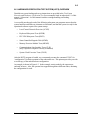
About This Publication
This publication is provided for users of the Enhanced Micro TDC 3000 Control System. Basic
information relating to installation, checkout, implementation, and operation are covered.
This publication is to be used in conjunction with the remainder of the TDC 3000X bookset.
This publication supports MicroTDC 3000 system software release 500. It also contains hardware
information about the ElectroMagnetic Compatibility Directive for European standards.
Any equipment designated as “CE Compliant” complies with the European Union EMC and
Health and Safety Directives. All equipment shipping into European Union countries after
January 1, 1996 require this type of compliance—denoted by the “CE Mark.”
Enhanced Micro TDC 3000 User’s Manual
9/95
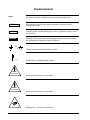
Standard Symbols
The following defines standard symbols used in this publication
Scope
ATTENTION
Notes inform the reader about information that is required, but not
immediately evident
CAUTION
Cautions tell the user that damage may occur to equipment if proper care is
not exercised
WARNING
Warnings tell the reader that potential personal harm or serious economic
loss may happen if instructions are not followed
OR
53893
53894
Ground connection to building safety ground
Ground stake for building safety ground
DANGER
SHOCK HAZARD
53895
Electrical Shock Hazard—can be lethal
DANGER
HIGH VOLTAGE
53896
Electrical Shock Hazard—can be lethal
53897
Rotating Fan—can cause personal injury
Enhanced Micro TDC 3000 User’s Manual
9/95
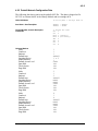
Table of Contents
1
INTRODUCTION AND OVERVIEW
1.1
1.1.1
1.1.2
1.1.3
1.1.4
1.1.5
1.2
1.2.1
1.2.2
1.3
1.4
1.4.1
1.4.2
1.5
1.6
2
General Description
Basic Enhanced Micro TDC 3000 Systems
Options to the System
The Operator’s Keyboard
The Engineer’s Keyboard
The Local Control Network
Operating Practices and Housekeeping
Before Startup
After Startup
Circuit Card Handling
Cartridge Disk Handling and Storage
Cartridge Loading and Removal
Cartridge Media Protection
EMC Directive
Related Publications
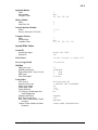
SITE PREPARATION AND INSTALLATION
2.1
2.2
2.2.1
2.3
2.3.1
2.3.2
2.3.3
2.4
2.5
2.6
2.7
2.7.1
2.7.2
2.7.3
2.7.4
2.7.5
2.7.6
2.7.7
2.7.8
2.7.9
2.7.10
2.7.11
2.7.12
2.7.13
2.7.14
Storage Conditions
Site Requirements
Dimensions and Weight
Electrical Requirements
AC Voltage Options
Frequency
Current in Amperes at 120 Vac
Unpacking
Site Layout
Installation
Tower #1 Equipment Cabling
Cabling - Standard
Cabling - EMC Directive
Cabling EPDG I/O Board - Standard
Cabling EPDGC I/O Board
Operator Keyboard Cabling
Printer Cabling
Color Monitor Cabling
Engineer’s Keyboard Cabling
TPLCN Cabling
Touchscreen Cabling
Trackball Cabling
Process Cabling
Cabling Diagram and Parts List–Track Ball
Cabling Diagram and Parts List–Touch
Enhanced Micro TDC 3000 User’s Manual
i
9/95
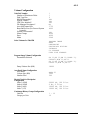
Table of Contents
2.8
2.8.1
2.8.2
2.8.3
2.8.4
2.8.5
2.9
2.10
3
CHECKOUT
3.1
3.1.1
3.1.2
3.1.3
3.1.4
3.1.5
3.2
4
Tower #2 Equipment Cabling
Optional Universal Station Upgrade
Optional Redundant Network Interface Module
Optional Computer Gateway CLI I/O
Optional Computer Gateway CLI/A I/O
Optional PLC Gateway
Optional LCN Upgrade
Installation Wrap-Up
Power-On Tests
Tower #1 Electronics Checks
Tower #2 Electronics Checks
Color Monitor Check
Printer Checks
Cartridge Drive Checks
System Checkout Wrap-Up
IMPLEMENTATION
4.1
4.1.1
4.1.2
4.2
4.2.1
4.2.2
4.3
4.3.1
4.3.2
4.4
4.4.1
4.4.2
4.4.3
4.5
4.6
Implementation Overview
Database Configuration
The Implementation Process
System Startup
Local Control Network Configuration
Prebuilt Network Configuration Data
Load Gateways and Modules
Loading the AM
Loading the NIM
Load the Process Manager
Standard Double-Sided Nonredundant PM Cabinet
Expanded Standard PM Cabinet
UCN/PM Box Point Configuration Data
Loading the PLCG or CG
Data Point Building
Enhanced Micro TDC 3000 User’s Manual
ii
9/95
Table of Contents
4.7
4.7.1
4.7.2
4.7.3
4.7.4
4.8
4.8.1
4.8.2
4.9
5
OPERATIONAL GUIDELINES
5.1
5.1.1
5.2
5.2.1
5.2.2
5.2.3
5.3
5.3.1
5.3.2
5.3.3
5.4
5.4.1
5.4.2
5.4.3
6
Custom Functions
Build Pictures
Build Free Format Logs
Configure Buttons
Prepare User-Written Programs
Area Database Configuration
Install the Area Database
Area Database Prebuilt Configuration Data
Configuration Completion
The Engineering and Operator Personalities
How to Load and Change US Personalities
Loading the Modules and Gateways
Loading the Application Module
Loading Network Interface Module and UCN Devices
Loading the History Module
System Operation
Calling Up Operating Displays
The Area Database
Keyswitch Access Levels
Monitor Operation
IDEK Model MF-5221
IDEK Model MF-8221
HITACHI Model HM-4821-D
SERVICE
6.1
6.2
6.2.1
6.2.2
6.2.3
6.3
6.3.1
6.4
6.5
6.6
Overview
Field Adjustments
LCN Node Addressing (Pinning)
UCN Node Addressing (Pinning)
21-Inch Monitor Adjustments
Cleaning
Air Filter Removal and Cleaning
Troubleshooting
Spare Parts
Hardware Verification Test System (HVTS) Overview
A
APPENDIX A
PREBUILT POINTS
B
APPENDIX B
BUTTON CONFIGURATION
INDEX
Enhanced Micro TDC 3000 User’s Manual
iii
9/95
Enhanced Micro TDC 3000 User’s Manual
iv
9/95
1
INTRODUCTION AND OVERVIEW
Section 1
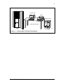
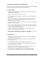
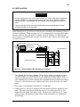
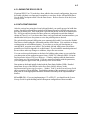
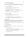
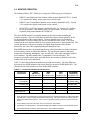
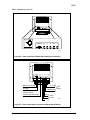
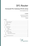
The Enhanced Micro TDC 3000 Control System is an extremely compact, yet fully
functional control system in the Honeywell TDC 3000X family. Figure 1-1 is an
illustration of the basic Enhanced Micro TDC 3000 Control System. This control system
communicates to the process via the Honeywell Universal Control Network (UCN). The
process can be monitored and controlled by Program Manager or Advanced Process
Manager.
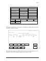
This manual describes the Enhanced Micro TDC 3000 system. The system comes in two
models. The model numbers are:
Model Number
Hardware Components
MX-DTAB01
K2LCN, 1 US, w/APM,
4MW AM, 875 MB HM.
MX-DTAC01
K2LCN, 1 US, w/APM,
8MW AM, 875 MB HM.
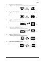
The Enhanced Micro TDC 3000 models have the following characteristics and features:
• Only “version A” models (with 1 US node) are offered as the base system. The
old”version B” models (with 2 US nodes) are no longer offered as a base system (the
old”version B” models are equivalent to a “version A” model, plus an optional US
node).
• All nodes are equipped with K2LCN processors.
• The base models will include an Advanced Process Manager (APM) as standard
equipment.
• The minimum AM processor memory is 4 MW (the base system models are offered with
AM nodes in two memory sizes — either 4 MW or 8 MW).
• The US included with the base system has 6 MW processor memory and supports
‘Universal’ personality.
• The US node in the base system is equipped with dual 150 MB Bernoulli cartridge
‘multi-drives’. The new ‘multi-drives’ are compatible with 35 MB
• The HM included in the base system has a 875 MB hard drive and 3 MW processor
memory.
• The NIM included in the base system has 3 MW processor memory.
• The US monitor and printer are not included with the “R500-Ready” Enhanced Micro
TDC 3000 models. These two peripherals have their own model numbers and must be
ordered separately. The operator’s keyboard, however, is included with the base system
model.
• The Enhanced Micro TDC 3000 models will not support UXS or AXM. There are
currently no plans to provide UXS or AXM options with the system.
Enhanced Micro TDC 3000 User’s Manual
1-1
9/95
1
Monitor (US)
Printer
Micro Towers
(Table Not Included)
APM
52565
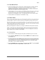
Figure 1-1 — Enhanced Micro TDC 3000 Control System
Enhanced Micro TDC 3000 User’s Manual
1-2
9/95
1.1
1.1 GENERAL DESCRIPTION
The Enhanced Micro TDC 3000 Control System consists of two cabinets (also called
"towers") which together contain the electronics, two cartridge disk drives, and a history
module. The cabinet electronics support up to four color monitors, four keyboards, and
optional touchscreens or trackballs. A printer is also connected to the system.
Two electronics modules, one housed in each tower, provide all of the electronics for the
Enhanced Micro TDC 3000 Control System (excluding peripherals). These modules,
called Multinode Modules, are each capable of holding four TDC 3000 Nodes.
Although the Advanced Process Manager (APM) is part of the Enhanced Micro TDC 3000
Control System, it is not described in this manual. See subsection 1.5 for a list of
publications that discuss the Advanced Process Manager and the Universal Control
Network (UCN).
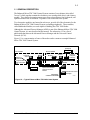
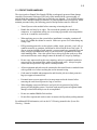
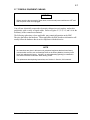
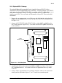
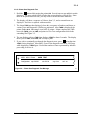
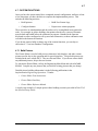
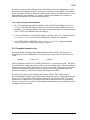
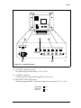
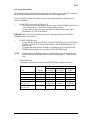
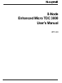
Figure 1-2 is a representation of some of the nodes used to construct a sample Enhanced
Micro TDC 3000 Control System.
(Example)
LEFT TOWER
DEC VAX
RIGHT TOWER
History
Module
Optional
Universal
Station
Optional
Enhanced
Programmable
Logic Controller
G t
Application
Module
Universal
Station
LCN
620 LCS
(Example)
Optional Redundant
Network Interface
Module
UNIVERSAL
CONTROL NETWORK
Optional
Computer
Gateway
Network Interface
Module
Advanced Process
Manager
54120
Figure 1-2 — Typical Enhanced Micro TDC 3000 Control System
Enhanced Micro TDC 3000 User’s Manual
1-3
9/95
1.1.1
1.1.1 Basic Enhanced Micro TDC 3000 Systems
The Enhanced Micro TDC 3000 Control System is furnished with one basic version. This
is the single US Micro TDC 3000.
The base version consists of two 4-node towers, an operator’s keyboard, an engineer’s
keyboard, a color monitor and printer (ordered seperately), and the Advanced Process
Manager. Four nodes are contained within the two towers:
1. US—UNIVERSAL STATION A window to the process—allows all information
supplied from process-connected devices, instrumentation subsystems, and
computers to be seen and used. The color monitor, two keyboards, an optional
touchscreen or trackball, two cartridge disk drives, and the ASPI-41 printer are
integral parts of the Universal Station.
2. AM—APPLICATION MODULE Performs calculations and control strategies that are
not possible or practical using only process-connected devices. The Application
Module has 4 or 8 megawords of memory.
3. NIM—NETWORK INTERFACE MODULE Connects the Enhanced Micro TDC 3000
Control System to a process controller, generally to a Advanced Process Manager.
4. HM—HISTORY MODULE Provides mass storage of software, system data, and
customer/user data.
1.1.2 Options to the System
Monitors, touchscreens or trackballs, and printers are options to all the Universal Stations
in all versions of systems. A touchscreen or trackball allows you to "point" to areas on the
graphic display and select operations to be performed. Without either of these options, you
must use directional keys (arrows) on the keyboards to navigate across the screen.
Up to four additional nodes, making a total of eight nodes, may be added to basic
Enhanced Micro TDC 3000 Control System. Choose from the following:
1. NIM—REDUNDANT NETWORK INTERFACE MODULE Provides a second path to the
process controller in the event of an electrical failure.
2. US—UNIVERSAL STATION (4Mw and 6Mw) Provides a window to the process.
3. EPLCG—ENHANCED PROGRAMMABLE LOGIC CONTROLLER GATEWAY Provides a
path to one or more Programmable Logic Controllers.
4. PLNM—PLANT NETWORK MODULE Provides the hardware and software to link the
LCN to the VAX interfaces.
5. CG—COMPUTER GATEWAY Provides a path to a host computer.
6. NG—NETWORK GATEWAY Provides a path to an alternate network for an integrated
plant solution (single and dual cable).
Enhanced Micro TDC 3000 User’s Manual
1-4
9/95
1.1.2
SYST
STAT
!
\
"
$
=
&
<
*
>
Q
W
E
R
T
Y
U
I
O
A
S
D
F
G
H
J
K
L
SP
Z
X
C
V
B
N
M
?
P
ALPHA
SHIFT
CONS
STAT
RECRD
CANCL
PRINT
FAST
PRINT
DISP
GROUP DETAIL
7
8
9
UNIT
TREND
TREND
4
5
6
BATCH
GO TO
1
2
SCHEM
HELP
•
0
3
_
DISP
SET
HOUR
AVG
PRIOR
DISP
ASSOC
DISP
DISP
BACK
DISP
FWD
PAGE
BACK
PAGE
FWD
PRINT
TREND
SYST
MENU
LOAD
MAN
AUTO
NORM
SP
OUT
ENTER
ACK
CLR
ENTR
SIL
MSG
SUMM
ALM
SUMM
MSG
CONFM
MSG
CLEAR
SELECT
ALM
ANNC
TAB
UNIT
ALM
SUMM
Qwerty Operator's Keyboard
CAPS LOCK
PF1
PF2
PF3
!
1
F1F1
CAPS
LOCK
ESC
"
2
F2
Q
SHIFT
LOCK
PF5
PF4
PF6
#
3
F3
$
4
F4
W
A
%
5
F5
E
S
PF7
R
D
PF8
PF9
PF10
/
&
F7
(
8
F8
)
9
F8
&
6
F6
T
F
Y
G
U
H
PF11
=
—
F11
O
F10
O
I
PF12
~
^
F12
`
@
P
+
;
L
K
J
PF12
DEL
RETURN
}
]
*
:
LF
:
`
SHIFT
Z
X
C
V
B
N
M
<
,
>
.
?
/
INS CHAR
PF14
ERASE
{
[
SHFT LOCK
PF15
DEL
CHAR
HOME
INS
CHAR
DEL
LINE
INS
LINE
CENT
PAGE
BACK
DISP
PAGE
FWD
DISP
PF16
7
BKGND
8
BLINK
4
5
WHT
9
HELP
MENU
6
CANCEL
BLK
2
3
CYAN
BLUE
MAGN
O
—
RED
LOAD
INTEN
1
SHIFT
YEL
ENTER
CTL
PF17
GRN
CLR-ENT
PRT
SCN
CMMND
SELECT
MAGN
BREAK
Engineer's Keyboard
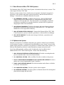
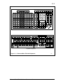
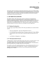
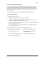
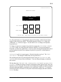
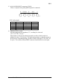
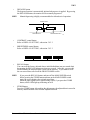
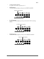
Figure 1-3 — Enhanced Micro TDC 3000 Keyboards
Enhanced Micro TDC 3000 User’s Manual
1-5
5891
9/95
1.1.3
1.1.3 The Operator’s Keyboard
The Operator's Keyboard (Figure 1-3) is a flat, chemically resistant, membrane keyboard
installed in a metal frame, placeable by the operator, and connected to the keyboard
connector on the transition panel. A three-function annunciator horn is built into these
keyboards.
Unmarked keys on the left side of the operator’s keyboard may be configured by the user
(or, perhaps, be preconfigured at the factory). An insert sheet is available that is placed
between the outside protective membrane and the keyboard electronics. To replace or
install a new insert, remove the two corner screws beneath the metal frame. Lift the frame
from the keyboard assembly, grasp the plastic insert using the thumb-slot at the top of the
keyboard and remove it. Replace it with the new insert. Reassemble the keyboard and
frame, then install and tighten the two corner screws.
Additional operator’s keyboards are supplied with optional Universal Stations.
1.1.4 The Engineer’s Keyboard
At least one engineer's keyboard (Figure 1-3), similar in design to a personal computer
keyboard, will be connected to the system. The engineer’s keyboard is especially designed
so that it may be disconnected and/or reconnected while the system is in operation. This
way, the keyboard may be removed when an engineer wishes to deny operator access to
special engineering functions, or the engineer may carry “his” keyboard to any operating
system.
To connect this keyboard, insert the plug on its cable into the small connector located on the
side of the operator’s keyboard. Note that the plug will only fit one way.
An engineer’s keyboard is optionally available, but not supplied with, the optional second,
third, or fourth Universal Station.
1.1.5 The Local Control Networks
All the nodes in both towers communicate with each other through the TPLCN (Twisted
Pair Local Control Network) data communications network, using the RS-485
communications interface standard. This network is similar to the LCN (Local Control
Network) used in other TDC 3000X equipment, but the noncoaxial RS-485 (twisted pair)
network has been chosen here because of its simplicity and the short physical distances
between nodes.
High-speed serial data is passed between nodes at 5 megabits per second (mega = million)
and follows a token-passing protocol. This protocol is identical to that used on the LCN.
There is a user-installed kit that connects the base Enhanced Micro TDC 3000 to a standard
LCN system. The kit includes an LCN cabinet that accommodates 4 or 6 empty chassis; a
fan module, power supply, and I/O card for each chassis; Winchester Disk Adapter (WDA)
Module; and History Module. Refer to subsection 2.9 for additional information on the
LCN upgrade.
Enhanced Micro TDC 3000 User’s Manual
1-6
9/95
1.2
1.2 OPERATING PRACTICES AND HOUSEKEEPING
Listed here are some do's and don'ts pertaining to operating practices and general housekeeping
that should be followed during startup and normal everyday operations.
1.2.1 Before Startup
1. Thoroughly clean all operating areas, subfloor areas, cable raceways, heating and airconditioning ducts, and plenums.
2. Make sure that all control-room windows are sealed.
3. Place impregnated mats at each entrance to a control area to prevent dirt and dust from
being tracked in.
4. Provide a coat rack and/or closet outside the operating area for removal of any outer
clothing made of nylon or other synthetic fabrics, except where flame-retardant
uniforms are mandatory at all times.
5. Make sure that the furniture and carpets are not made of materials that can combine with
clothing to create static electricity.
6. Prepare a regular cleaning schedule for specific area requirements and for cleaning of
consoles, cabinets, and peripheral devices where necessary. (Caution: Do not attempt
to clean the printed-wiring boards themselves.)
7. Establish a "no-smoking" rule in the operating area. Smoke and other fine dust
particles can damage cartridge disks and drives.
8. When swapping or handling printed-circuit cards, use a static-control device, such as a
wrist strap; see Circuit Card Handling, subsection 1.3 of this manual.
1.2.2 After Startup
1. Continue your "no-smoking" rule in the operating area. Smoke and fine dust particles
can damage cartridge disks and drives.
2. Maintain humidity levels (ideally) between 40 and 60% (lower humidity may cause
static-discharge problems).
3. Control humidity fluctuations to a rate-of-change less than 6% per hour.
4. Do not defeat temperature and humidity controls by opening doors and windows (for
example, to enhance operator comfort).
5. Keep traffic in the control-room operating areas to a minimum. Restrict access to
authorized personnel, whose duties require control room entry.
6. Review procedures for extinguishing electrical fires and establish fire-fighting
procedures. Refer to a qualified fire-fighting systems contractor for assistance.
Enhanced Micro TDC 3000 User’s Manual
1-7
9/95
1.2.2
7. Plant personnel frequently use hand-held radios ("walkie-talkies"), or citizens-band
radios mounted in maintenance vehicles, for communications. To avoid RFI problems,
review the following:
•
If radio communications must take place within an operating area or process
controller area, a base-station transceiver with an external antenna should be
used.
•
For other applications, radio transmitters with outputs rated as high as 5 watts
must be kept at least 3 meters (10 ft.) from the Enhanced Micro TDC 3000
equipment during operation. Transmitters with outputs higher than 5 watts
must be kept as far as possible from your equipment. Keep equipment doors
closed while operating.
Other sources of RFI include generators, arcing relays, or motor contacts, etc.
8. Follow proper cleaning procedures when cleaning the operator area or the control room:
•
Do not use water freely. Mop should be only dampened, not wet or dry.
•
Use a lint-free, antistatic-type dust cloth to remove dust.
•
Do not sweep around areas containing cartridge disks or drives.
•
Use a vacuum cleaner on carpets—preferably one connected to an external
system.
•
Do not allow liquids to be placed on the Enhanced Micro TDC 3000 keyboards
and equipment. Liquid spills will damage electronic components.
9. Clean the cartridge disk drive as outlined in the Universal Station Service manual in the
LCN Service - 1 binder to prevent errors and loss of data when loading programs.
10. Regularly clean the CRT face to minimize operator fatigue. Cleaning procedures are
found in Universal Station Service manual in the LCN Service - 1 binder.
11. Clean the printer before startup and periodically thereafter, as described in the
Universal Station Service manual in the LCN Service - 1 binder.
12. Periodically clean the operator and engineer keyboards by dampening a cloth with mild
detergent and wiping the keys. Do not spray detergent solution on the keys as moisture
may ruin the circuits underneath.
13. Periodically check and clean or replace the air filters in each cabinet. Refer to
subsection 6.3.1 of this manual for filter removal and cleaning procedures.
Enhanced Micro TDC 3000 User’s Manual
1-8
9/95
1.3
1.3 CIRCUIT CARD HANDLING
The circuit cards or Printed Wire Boards (PWBs) are adequately protected from damage
caused by Electrostatic Discharge (ESD) only while installed in the system module, or
packed inside the conductive plastic bag in which they are shipped. To avoid ESD damage
when the card is handled outside its enclosure, to guard against electrical overstress, and to
maintain personnel safety, the following practices and procedures must be followed:
•
Turn off power to the module before removing or inserting the card.
•
Handle the card only by its edges. Do not touch the printed wire board runs,
connectors, or components unless you are wearing a grounded wrist-strap and the
card is on a conductive work-surface.
•
When applying power to the system before installation is complete, terminate all
loose wires within the cabinet or console. Make sure power is off when doing any
wiring work.
•
ESD-generating materials, such as plastic, rubber, nylon, polyester, vinyl, silk, or
synthetic materials or garments, should not be allowed in the area of the cards. If
you are wearing clothing of such material, you must stand on a grounded floor-mat
while wearing a grounded shoe-strap, or you must wear a grounded wrist-strap
while handling cards. Note: take special care to always keep the cards away from
such material because static charges cannot be drained off, except by discharge.
•
Do not carry unprotected cards across carpeting, unless it is grounded conductive
carpet such as conventional fiber with woven-in ground wires. Always keep the
circuit card in its protective bag until it is actually needed.
•
All test equipment and tools must be connected to the metal chassis or module frame
with a ground wire, before touching the card or internal wiring.
•
Cards must be handled and transported to and from the job site in their protective
bags (see approved material list).
•
Personnel must wear an approved wrist-strap connected to the chassis before
removing the card from its protective bag or card slot.
•
When shipping a suspected defective card, pack it in its protective bag before
placing it in the shipping carton. Note that cards must be protected against further
damage so that failure analysis can be accomplished.
•
Do not use standard Bubble Pack mailers.
•
Do not allow unprotected cards to come in contact with Styrofoam packing material.
For additional ESD information, refer to the LCN Planning manual in the System Site
Planning - 1 binder.
Enhanced Micro TDC 3000 User’s Manual
1-9
9/95
1.4
1.4 CARTRIDGE DISK HANDLING AND STORAGE
Upon receipt of cartridge disks, inspect them for signs of shipping damage. Allow at least
one hour for temperature adjustment to the computer-room environment before using.
Recommended storage is on shelves in the computer or control room.
Although the cartridge protects the disk from most accidental damage, the following
cartridge handling rules should be observed:
•
Do not try to open the cartridge when it is outside the drive.
•
Do not insert objects into the cartridge or drive.
•
Remove the cartridge from the drive after use and store in its protective jacket.
•
Do not expose the cartridge to direct sunlight or moisture.
•
Do not expose the cartridge to magnetic fields greater than 30 oersteds.
•
Protect the cartridge from dirt, spills, and harsh environments.
•
Avoid handling the front edge of the cartridge, since oils can be transferred from the
hands to the cartridge disk.
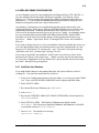
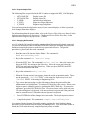
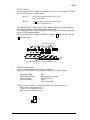
1.4.1 Cartridge Loading and Removal
1. Drive power must be on before the cartridge can be inserted. If power to the drive is
off, the latch pin in the drive will prevent cartridge insertion.
2. The cartridge is inserted into the drive shutter first. The cartridge edge containing the
shutter faces toward the stop button on the front of the drive (see Figure 1-4).
Interlocks in the system prevent improper cartridge insertion.
CAUTION
If the cartridge is difficult to insert, check its orientation and try again. Do not force the
cartridge into the drive. Objects inserted into the cartridge opening in the front of the drive
may cause damage to the drive. Such action will void the manufacturer's warranty.
3. After loading a cartridge, the green indicator on the front of the drive, next to the stop
button, blinks as the motor is coming up to speed. When the indicator stops blinking
and stays lit, the drive is READY (see Figure 1-4).
Enhanced Micro TDC 3000 User’s Manual
1-10
9/95
1.4.1
NOTE
The yellow LED flashes briefly as the drive reads initialization information from the disk. If the
drive fails to initialize correctly, an error condition exists. If this occurs, reinsert the cartridge to
ensure proper seating. If this does not correct the problem, the media may require
reformatting or the drive may require service (see Figure 1-4).
4. To remove the cartridge, push the stop button. The green LED then begins to blink as
the motor spins down. When the motor has stopped, the green LED turns off and the
latch pin disengages. The cartridge can now be removed (see Figure 1-4).
Insert Cartridge Here
Shutter
Yellow
LED
Stop
Button
Green
LED
Write Protect
Position
Figure 1-4 — Cartridge Drive and Disk
Enhanced Micro TDC 3000 User’s Manual
L
Unprotected
Position
1-11
Insert
Cartridge
This Way
52400
9/95
1.4.2
1.4.2 Cartridge Media Protection
To protect stored media (programs and data) on a cartridge from being accidentally erased,
you must move the protect switch (lower left in Figure 1-4) to the write protect position.
CAUTION
DON'T attempt to move the protect switch on the cartridge while the cartridge is installed in
the drive.
If the protect switch is moved to the unprotected position, the cartridge is free to be written
on by the Enhanced Micro TDC 3000 system—data and programs may be lost.
1.5 EMC DIRECTIVE
The Enhanced Micro TDC 3000 system is being brought into compliance with European
guidelines for ElectroMagnetic Compatibility (EMC). The European EMC directive
(89/366/EEC) requires that an electronics product operate reliably in its intended EMC
environment. It also requires that the product not detrimentally affect other products
operating in their own environment.
L
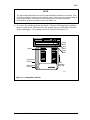
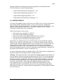
Eventually the Enhanced Micro TDC 3000 hardware will display a product certification
label to indicate the hardware is in compliance. This label is placed inside, at the bottom
front of the tower. As shown in Figure 1-5, a “CE” logo on the product label indicates the
product is in compliance with the European EMC directive along with other descriptive
information about the product.
System Identification Code 'SID'
(3 Alpha / Numeric Character
That Identifies Customer)
European Compliance Logo
S
*** = 000 to 999
(3 Numeric Digits to Identify Each
Bay Within a Console Complex)
PHOENIX, ARIZONA
FO
EN
M
A
TDC 3000 SYSTEM
XX = 01 to 99
(2 Numeric Digits For
Each Micro Complex)
MODEL NO
POWER
MWXX 'SID' - ***
511XXXXX - ***
120
VAC 60
HZ
MAX CURRENT
120 VAC = 120
230 VAC = 230
Power
10.0 X1
12.5 X1
120 VAC = 10.0 x 1 Right Tower
12.5 x 1 Left Tower
230 VAC = 5.0 x 1 Right Tower
6.25 x 1 Left Tower
Current
AMPS
Part Number of Unit
511XXXXX- ***
8 Digits
(Build Options
*** = 100/200
120 VAC = 120
230 VAC = 230
Power
(100 = 120 VAC)
(200= 230 VAC)
53648
Figure 1-5 — Product Certification Label
Enhanced Micro TDC 3000 User’s Manual
1-12
9/95
1.6
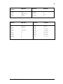
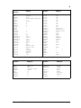
1.6 RELATED PUBLICATIONS
The following publications apply to the Enhanced Micro TDC 3000 system and should be
referred to as required and available:
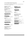
Title
Binder
8 Node Enhanced Micro TDC 3000 Specification and
Technical Data
8 Node Enhanced Micro TDC 3000 User's Manual [this
pub]
8 Node Multinode Module Service
System Summary - 2
History Module Service
System Maintenance Guide
Test System Executive
Hardware Verification Test System
Core Module Test System
Maintenance Test Operations
LCN Service - 2
LCN Service - 1
LCN Service - 3
LCN Service - 3
LCN Service - 3
LCN Service - 1
Process Operations Manual
Operation/Process Operations
Universal Control Network Planning
Universal Control Network Installation
Universal Control Network Guidelines
Universal Control Network Specification
and Technical Data
System Site Planning - 1
Installation/Universal Control Network
Installation/Universal Control Network
System Summary - 2
PM and APM Planning
Process Manager/Advanced Process Manager
Installation
Process Manager/Advanced Process Manager
Implementation Guidelines
Process Manager/Advanced Process Manager
Checkout
System Site Planning - 1
Implementation/PM/APM
Process Manager/Advanced Process Manager Service
Process Manager Module Test System (PMMTS)
Process Manager Test System (PMTS)
Process Manager Test Executive (PMEX)
PM/APM/HPM Service -1
PM/APM/HPM Service -2
PM/APM/HPM Service -2
PM/APM/HPM Service -2
Enhanced Micro TDC 3000 User’s Manual
1-13
Implementation/8-Node Enhanced Micro
TDC 3000
Implementation/8-Node Enhanced Micro
TDC 3000
Implementation/Advanced Process
Manager - 1
Implementation/PM/APM
9/95
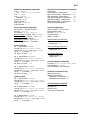
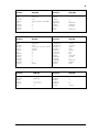
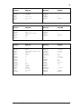
1.6
Title
Binder
Enhanced Programmable Logic Controller Gateway
Planning, Installation, and Service
Implementation/EPLC Gateway
Enhanced Programmable Logic Controller Gateway
Specification and Technical Data
System Summary - 2
Enhanced Programmable Logic Controller Gateway
Control Functions
ImplementationE/PLC Gateway
Enhanced Programmable Logic Controller Gateway
Parameter Reference Dictionary
Implementation/EPLC Gateway
Enhanced Programmable Logic Controller Gateway
Forms
Implementation/EPLC Gateway
MTX-MTLU11 Upgrade Kit Installation Instructions
MTX-MTLU12 Upgrade Kit Installation Instructions
MTX-MTLU13 Upgrade Kit Installation Instructions
MTX-MTLU14 Upgrade Kit Installation Instructions
Not
Not
Not
Not
Enhanced Micro TDC 3000 User’s Manual
1-14
Applicable
Applicable
Applicable
Applicable
9/95
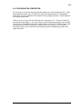
2
SITE PREPARATION AND INSTALLATION
Section 2
This section provides the following information for the Enhanced Micro TDC 3000 Control
System: Storage conditions, site requirements, electrical requirements, unpacking, cabling, and
node addressing.
2.1 STORAGE CONDITIONS
The Enhanced Micro TDC 3000 Control System is protectively wrapped for shipment in a
dry-wall pack. The electronics modules, color monitor, operator’s keyboard, engineer’s
keyboard, touchscreen, trackball, and printer are in separate packages.
If the Enhanced Micro TDC 3000 Control System is to be placed in storage, the
environmental constraints listed here must be followed:
Temperature
Humidity (RH)
Shock*
-10° + 70°C
10 - 80%, max wet bulb 20 - 30°C
3.0 g for 10 milliseconds
* When enclosed in the original shipping container.
Note that the temperature/relative humidity shall not be cycled such that moisture
condensation occurs on the equipment—rate of change less than 6% per hour. The storage
shipping requirements are for one year duration only, provided the equipment is properly
packaged and contains an adequate amount of desiccant (moisture removing agent).
2.2 SITE REQUIREMENTS
The Enhanced Micro TDC 3000 Control System is designed for a Class C (office)
environment. It must be operated in a temperature environment of 0°-45°C (32°-113°F).
While operating, components of this system are not designed to withstand greater vibration
than:
5-22 Hz
22-500 Hz
0.254 mm (0.010 inch) displacement
0.25 g
For US systems, each electronics module, the monitor(s), and the printer are equipped with
1.8 meter (6 foot) NEMA 5-15P, power cords. For the basic Enhanced Micro TDC 3000
System (refer to subsection 1.1.1), there must be at least two duplex, 120 Vac, grounded,
NEMA 5-15R, electrical outlets accessible to these items. These outlets must be tied to the
same ground.
If your system is equipped with additional color monitors, there must be at least three
duplex, 110 Vac, grounded, NEMA 5-15R, electrical outlets, all tied to the same ground.
Additional outlets are also needed if certain options are installed—for example, the EPLCG
option may use a free-standing modem powered from 110 Vac lines.
Enhanced Micro TDC 3000 User’s Manual
2-1
9/95
2.2.1
International models (240 Vac) of the Enhanced Micro TDC 3000 Control System are
equipped with 1.8 meter (6 foot) power cords having CEE-7 standard VII dual earthing
plugs. Likewise, there must be four (or more) CEE-7 standard VII dual earthing electrical
outlets provided, all tied to the same ground.
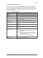
2.2.1 Dimensions and Weight
These are the approximate dimensions and weight for each electronics tower, color
monitor, UCN cabinet (APM) and printer:
Electronics Tower (each)
Height
Width
Depth
Weight
72 cm
32 cm
58 cm
45 kg
(28.3")
(12.6")
(22.8")
(99.2 lb)
Advanced Process Manager
(Dual-Access)
Height
Width
Depth
Weight
Printer (ASPI-41)
Height
Width
Depth
Weight
17 cm
62 cm
31 cm
14 kg
47.1 cm
49.2 cm
53.6 cm
33 kg
(81.5”)
(31.5”)
(31.5)”
(440 lb)
Color Monitor (20”)
(6.7")
(24.4")
(12.2")
(30.8 lb)
Height
Width
Depth
Weight
IDEK Color Monitor (21”)
Height
Width
Depth
Weight
210 cm
80 cm
80 cm
200kg
(18.5")
(19.4")
(21.1")
(72.7 lb)
44.9 cm
49.8 cm
53.4 cm
29 kg
(17.7")
(19.6")
(21.0")
(63.9 lb)
HITACHI Color Monitor (21”)
Height
Width
Depth
Weight
47 cm
50 cm
51 cm
34 kg
(19.7")
(18.5")
(20.1")
(74.9 lb)
For Advanced Process Manager dimensions and weight, consult Process Manager
/Advanced Process Manager Planning, part of the System Site Planning - 1 binder.
2.3 ELECTRICAL REQUIREMENTS
The customer selected ac power option is installed in the Enhanced Micro TDC 3000
Control System before shipment.
The inrush current to each electronics module is limited to 15 A @ 120 V.
2.3.1 AC Voltage Options
120, 240 Vac +10%, -15%
2.3.2 Frequency
47 Hz to 63 Hz
Enhanced Micro TDC 3000 User’s Manual
2-2
9/95
2.3.3
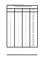
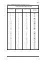
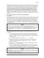
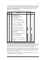
2.3.3 Current in Amperes at 120 Vac
Avg
True RMS
Peak
Wattage
BTUs/hr
Twr #1 (1 US, AM, NIM, & drives)
typical
1.65
3.53
10
266
907.06
Twr #1 (2 US, AM, NIM, & drives)
typical
1.95
4.12
11.2
319
1087.79
Twr #1 (1 US, AM, NIM, CG, & drives) typical
2.01
4.25
11.4
329
1121.89
Twr #2 (HM only)
typical
1.15
2.54
6.5
185
630.85
Twr #2 (HM & US)
typical
1.54
3.34
9.5
249
849.09
Twr #2 (HM, US, & US)
typical
1.84
3.91
10.7
299
1019.59
Twr #2 (HM, US, & CG)
typical
1.95
4.12
11.2
319
1087.79
Monitor, 20 inch CRT
typical
0.5
1.14
3.1
79
269.39
Monitor, 21 inch CRT
typical
0.8
1.5
4.1
83
283
ASPI-41 Printer
typical
1.1
1.75
9.1
210
716
For Advanced Process Manager power consumption, consult Process Manager /Advanced
Process Manager Planning, part of the System Site Planning - 1 binder.
2.4 UNPACKING
When the equipment arrives at the system site, open each shipping box, remove the
protective wrapping and carefully inspect each piece for any physical damage. If damaged,
immediately notify the carrier and your Honeywell sales representative as to the extent and
type of damage. Also check each piece of equipment against the invoice list for any missing
items.
CAUTION
Optional touchscreens will be factory installed. Be careful not to lift the CRTs by holding the
touchscreen bezel. Due to the weight you may easily damage the touchscreen.
Enhanced Micro TDC 3000 User’s Manual
2-3
9/95
2.5
2.5 SITE LAYOUT
1 Meter
Figure 2-1 shows a typical installation of the Enhanced Micro TDC 3000 System in a
minimum-sized 4 meter x 4 meter (13.1 foot x 13.1 foot) area. Allow a minimum of one
meter (3.3 feet) behind and to the side of the equipment for cabling and service.
Tower
#2
53.4 cm(21")
61 cm (24")
Chair
1
Meter
30.5 cm (12")
49.8 cm
(19.6")
Tower #1
80 cm (31.5")
(All Four Sides)
Dual
Access
Cabinet
53281
Figure 2-1 — Enhanced Micro TDC 3000 System Layout—Top View
The dual access Advanced Process Manager cabinet is included with the Enhanced Micro
TDC 3000 System and is shown for reference in Figure 2-1. Complete planning and
installation instructions for the Advanced Process Manager are given in the Process
Manager/Advanced Process Manager Planning, part of the System Site Planning - 1 binder
and Process Manager/Advanced Process Manager Installation manual, part of the
Implementation/PM/APM binder.
Enhanced Micro TDC 3000 User’s Manual
2-4
9/95
2.6
2.6 INSTALLATION
WARNING
DO NOT apply power to any of the Enhanced Micro TDC 3000 Control System equipment
until this installation is completed and this manual tells you to do so. Be sure the power
switches are OFF on all equipment and that no power cords are plugged into electrical ac
mains.
Failure to heed this caution may subject personnel to severe electrical shock or cause
permanent damage to the equipment.
In the following steps, you will move relatively heavy and bulky units containing sensitive
electronic equipment. When moving a tower, we recommend you use two people to place
the tower on a low, flat, roller dolly for transfer within the building. If a hand-truck is
used, it must be well-padded and you must use care not to put excessive stress on the short
feet under the tower.
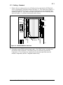
Operator's Keyboard
ASPI-41
Printer
Engineer's
Keyboard
25.4 cm
(10")
45.5 cm
(17.9")
Color Monitor
Cartridge Drive (2)
Power Switches
Status Indicators
(Table Not Included)
Tower #2 Tower #1
53282
Figure 2-2 — Enhanced Micro TDC 3000 System—Front View
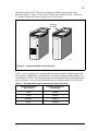
1. First, identify the electronics cabinets. These cabinets (towers) are shown in Figure
2-2 (and in Figure 2-1 with shaded lines). The towers look nearly identical, with a
translucent panel and a power switch near the middle-front of each cabinet. Tower #1
can be identified by two black cartridge drives installed near the top-front of its cabinet.
Tower #1 is also referred to as the “right 4-node” tower; tower #2 as the “left 4-node”
tower.
2. Do not place Color Monitors closer than 12” to each other.
3. Using Figures 2-1 and 2-2 as examples, place the towers in position, parallel to each
other. The printer must be positioned near tower #1 for connection to US #1, but
within the 6 foot length of the printer cable. Put the towers within 84 cm (33") apart
(unless you have the optional 10 meter cable). Make sure both towers sit firmly on
level flooring.
Enhanced Micro TDC 3000 User’s Manual
2-5
9/95
2.7
2.7 TOWER #1 EQUIPMENT CABLING
CAUTION
Before removing the rear panel of either tower, ensure that all power switches are OFF and
that the power cords are unplugged.
You will now electrically connect the electronics cabinets (towers) together, and to their
peripherals, with a variety of signal cables. Refer to Figures 2-3, 2-4, 2-5, and 2-6 for the
location(s) of the connectors mentioned.
The following subsections, where applicable, may contain information on the EMC
Directive that affects the hardware. When applicable, the EMC hardware information will
usually follow the hardware that is not in compliance with the directive.
NOTE
No instructions are given in this section for peripheral equipment that has been factory
mounted within a tower, such as Cartridge Drives or the History Module, since they have
been fully cabled at the factory. Likewise, no node addressing (pinning) is contained in
this section because nodes have been factory pinned.
For replacement board pinning instructions, see Section 6—Service, of this manual.
Enhanced Micro TDC 3000 User’s Manual
2-6
9/95
2.7.1
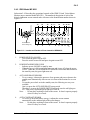
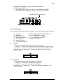
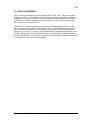
2.7.1 Cabling – Standard
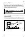
1. Remove the rear center-section cover of both towers by removing four M5 flat-head
screws, exposing the I/O boards as shown in Figure 2-3. The cards seen in Figure 2-3
are a typical example for Tower #1. Note some connectors are not used and are only
outlined in Figure 2-3. The cables from these card connectors to the transition panels,
shown in Figure 2-5, will have been installed at the factory.
10
9
8
7
6
5
4
3
2
1
Cartridge
Drives
UCN-A
Printer
UCN-B
CRT
Unused
NIM MODEM
TP485
EPDGP I/O
TP485
KBD
53283
Figure 2-3 — Multinode Module—Rear View
2. Note there are two TP485 cards, in slots 1 and 9. The TP485 in slot 9 of each tower
provides the TPLCN interface. The TP485 in slot 1 in each tower provides the
connection, at J3 (see Figure 2-4), and interface for thermocouples that sense the
module’s temperature (non-EC Compliant modules only).
Enhanced Micro TDC 3000 User’s Manual
2-7
9/95
2.7.1
R6
R5
R4
R3
R2
R1
R12
R11
R10
R9
R8
R7
51304776-100
J1
J3
J2
J1
J2
TP485
53284
Figure 2-4 — TP485 I/O Board
3. The standard cabling connections you will make in the following steps are on the
transition panels in Figure 2-5. Note there are two exposed transition panels—one at
the top of the center section and another at the bottom (see Figure 2-5). The panel has
connectors and cable clamps on it that will be used to secure cables you will install.
Both towers have the same locations for specific connector/clamp brackets but the
bracket types in certain locations may differ depending on the options installed.
Trackball (Option)
Optional Second
US In Tower
Blank
CRT
CRT
Keyboard
Touchscreen (Option)
Optional PLCG
Relay Panel
UCN A & B
Cables (Option)
Options:
PLCG, CG, NG
UCN Taps
Ground (Option)
TPLCN
Printer
53285
Figure 2-5 — Transition Panel Connections—Tower #1 (left) or #2 (right)
4. Note the Optional PLCG Relay Panel in Figure 2-5 above. It can be mounted above the
transition panel, as shown, in the tower containing an optional EPLCG (see Section
2.8.5).
Enhanced Micro TDC 3000 User’s Manual
2-8
9/95
2.7.2
2.7.2 Cabling – EMC Directive
Generally, EMC Directive cabling on the LCN systems follow these rules:
• any cable exiting an enclosure is shielded
• cable shields are terminated at both ends of the cable to chassis ground
• metallic connector housings (back-shells) completely enclose the cable for contiguous
shield
• braid or braid over foil is used on coaxial cables
• foil is used as a sheild where applicable (on multi-pair cables).
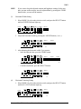
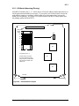
1. Remove the rear center-section cover of both towers by removing four M5 flat-head
screws, exposing the EMC Directive I/O boards as shown in Figure 2-6. Note that the
I/O boards have the face plates attached to the free edge of the board. The face plates
are secured to the sheet metal module with screws. The cards seen in Figure 2-6 are a
typical example for Tower #1. Note some chassis slots are not used and have filler face
plates covering the board slot. The cables from these board face plates to the transition
panels will have been installed at the factory.
10
9
8
7
6
5
4
3
2
1
UCN-A
VIDEO
J2
SCSI
UCN-B
J3
NIM MODEM
BUS A
CURSOR
BUS A
BUS B
PRINTER
BUS B
RX-B TX JP1
KEYBD
NIM MODEM
TP485
EPDGP I/O
TP485
53655
Figure 2-6 — Multinode Module for EMC Directive—Rear View
2. Note there are two TP485 cards, in slots 1 and 9. The TP485 in slot 9 of each tower
provides the TPLCN interface. The TP485 in slot 1 in each tower provides the
connection, at J3 (see Figure 2-4), and interface for thermocouples that sense the
module’s temperature (non-EMC Directive equipment).
Enhanced Micro TDC 3000 User’s Manual
2-9
9/95
2.7.2
3. For EMC Directive cabling, the connections you will make in the following steps is on
the transition panel shown in Figure 2-7. Note there is one exposed transition panel
located at the bottom (see Figure 2-7). The panel has connectors and cable clamps on it
that will be used to secure cables you will install. Both towers have the same locations
for specific connector/clamp brackets but the bracket types in certain locations may
differ depending on the options installed.
Optional PLCG
Relay Panel
Touchscreen (Option)
or
Trackball (Option)
Options:
PLCG, CG, NG
UCN Taps
Ground (Option)
53899
Figure 2-7 — Transition Panel Connections for EMC Directive—Rear View
4. Note the Optional EPLCG Relay Panel in Figure 2-5 above. It can be mounted above
the transition panel, as shown, in the tower containing an optional EPLCG (see Section
2.8.5).
Figure 2-8 and Figure 2-9 shows the EMC Directive TP-485-3 I/O board face plate. The
designed cable(s) attached to this card face plate is also terminated to ground (sheet metal
module) through the attaching screw on the face plate. This I/O board provides the current
loop interface between the modules located in an Enhanced Micro TDC 3000 tower.
Enhanced Micro TDC 3000 User’s Manual
2-10
9/95
2.7.2
BUS A
BUS B
53386
Figure 2-8 — TP-485-3 I/O Face Plate
ASSY NO.
51304766-300
REV D
J1
BAR CODE
J2
TP485
53360
Figure 2-9 — TP-485-3 I/O Board
Enhanced Micro TDC 3000 User’s Manual
2-11
9/95
2.7.3
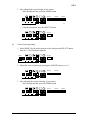
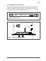
2.7.3 Cabling EPDGP I/O Board
EPDGP I/O boards (see Figures 2-10 and 2-11) interface nearly all the peripherals of the
Enhanced Micro TDC 3000 Control System. You are now going to connect those cables
which could not be installed at the factory.
TSI Orientation
J10
J9
Engineer
Keyboard
Supervisor
Keyboard
J1
0 1
Default CRT Background
J9 J10
1
1 Black
0
1 Light Grey (Dim)
1
0 Med. Grey (Brighter)
0
0 Warm Grey (Brightest)
0 1
J8
51304584-300
EPDGP I/O
J11 Pinning
Jumper Vertical Sync
Signal
TS1
J11
J2
J7
J5
J3
J4
J6
DIRECT
DIR VSYNC INV
INVERT
51090
Figure 2-10 — CRT Background Shade Pinning and Sync on the EPDGP I/O
EPDGP I/O boards can be pinned for default background shading(J9 and J10) and vertical
sync (J11) for the monitor as shown in Figure 2-10.
SCSI
51304584-300
EPDGP I/O
J2
Trackball/Mouse Connector
J1
J8
Mouse Adapter Cable #51304033-045
TS1
J7
Power (Touchscreen/Keyboard)
J11
J3
J5
J4
J6
Engineer Keyboard
Printer Connector
CRT Adapter Cable
Cable from CRT
Supervisor Engineer
Keyboard Keyboard
51091
Mouse or Trackball
Figure 2-11 — EPDGP-I/O Cabling
Universal Station Type
Classic with keyboard power supply
Classic without keyboard power supply
Ergonomic furniture with 21” FST monitor
Enhanced Micro TDC 3000 User’s Manual
EPDGP I/O Assembly
51304584-100
51304584-200
51304584-300
2-12
9/95
2.7.4
2.7.4 Cabling EPDGC I/O Board
The EPDGC I/O is the EMC Directive board version used to interface with the monitor,
keyboard, touchscreen, SCSI cartridge drives and printers. The EMC Directive version is
shown in Figures 2-12 and 2-13. All the connectors have been converted to D-type
connectors with full 360 degree shielding. The connectors are bulkhead mounted into the
board face plate which provides a contiguous shield from module to cable. The cabling of
peripheral devices are connected at this face plate. The Touchscreen and Trackball cables
are connected to the cabinet bulkhead shown in Figure 2-7.
VIDEO
SCSI
CURSOR
PRINTER
KEYBD
53369
Figure 2-12 — EPDGC I/O Face Plate
The background color of the monitor can be selected as one of four colors as shown in
Figure 2-13. The pinning shown is for the default background color. Pin the board for
desired background color. The pinned background color selection is only in force until the
station is loaded with software.
The sync pulse requirements of the monitor used is pinned at J6 (factory set) as shown in
Figure 2-13. The pinning of J6 will determine the tab number of the board and is factory
set. The monitor sync pulse source will either be direct (Tab 100) or inverted (Tab 200).
BAR CODE
EPDGC I/O
ASSY NO. 51402447-100 REV A
J7
J8
0 1
0 1
Default CRT Background
J7 J8
1
1 Black
1
0 Dark Grey
0
1 Med. Grey
0
0 Light Grey
Tab 100 - "DIR"
Tab 200 - "INV"
Factory Set
J6
J1
J2
J3
J4
J5
53389
Figure 2-13 — EPDGC I/O Pinning
Enhanced Micro TDC 3000 User’s Manual
2-13
9/95
2.7.5
2.7.5 Operator Keyboard Cabling
Connect the keyboard cable to the connector on the face plate of the EPDGC I/O board (see
Figure 2-11). Use a small screwdriver to tighten the screws (2) on the connector.
2.7.6 Printer Cabling
The printer cable (51303631-003) has similar connectors on each end.
1. Connect the end of the cable marked PIC to the connector on the face plate of the
EPDGC I/O board marked PRINTER in Figure 2-11. Use a small screwdriver to tighten
the screws (2) on the connector.
2. Connect the other end of the printer cable (marked PRINTER) to the back of the printer.
Using a small screwdriver, tighten the screws (2) on the connector.
2.7.7 Color Monitor Cabling
Connect the cable from the color monitor to the EPDGC I/O face plate connector marked
Using a small screwdriver, tighten
the screws (2) on the connector. Finally, attach the power cord to the monitor and plug it
in.
VIDEO in Figure 2-11. on the upper transition panel.
2.7.8 Engineer’s Keyboard Cabling
Insert the plug on the cable from the engineer’s keyboard into the small connector located
on the right of the operator keyboard. Note the plug will only fit one way.
2.7.9 TPLCN Cabling
The two (2) TPLCN cables (51304505-100) have similar connectors on each end. The
standard cable length is 5 feet (1.5 meters). The optional cable (Option number
MX-MTLC11) is 33 feet (10 meters) long, allowing a maximum distance between towers
of 10 meters. The cable set connects directly to the TP-485 board face plates in the towers.
1. Attach one cable plug to the TP-485 face plate connector marked BUS A and the other
cable plug to BUS B at the rear of Tower #1. Using a small screwdriver, tighten the
screws (2) on the connectors.
2. Attach the other end of the cable to the TP-485 face plate connector marked BUS A and
the other cable plug to BUS B at the rear of Tower #2. Use a small screwdriver to
tighten the screws (2) on the connectors.
3. Attach the ground wires to the small screws, if they are on your cable.
Enhanced Micro TDC 3000 User’s Manual
2-14
9/95
2.7.10
2.7.10 Touchscreen Cabling
The optional Touchscreen and Trackball are not to be used together on the same US, so
they share the same connector (J1) on the EPDGP I/O card. When the Trackball or
Touchscreen is selected are bulkhead connected at the transition panel (see Figure 2-7).
1. The cables from the optional touchscreen pass through the clamps in the left location
marked TOUCHSCREEN on the lower transition panel in Figure 2-5, and are to be
connected to the EPDGP I/O card in slot 2 as shown in Figure 2-6.
2. Plug the large connector into J1, marked TOUCHSCREEN or TRACKBALL in Figure
2-6, on the EPDGP I/O card and the small connector into J4, marked POWER in
Figure 2-6. The EPDGP I/O card may have to be partially or completely pulled out to
make these connections. Use proper board handling precautions, including a grounded
wrist-strap, to extract the card. Use care not to disturb or dislodge existing cables and
then firmly reseat the card.
3. Using a cable-tie (51190879-001) on each cable, fasten the cables to their strain-relief
clamps on the upper transition panel.
2.7.11 Trackball Cabling
The cable from the optional trackball is to be connected to the lower transition panel at the
left location marked Trackball in Figure 2-5. Use a small screwdriver to tighten the screws
(2) on the connector. In accordance with the user’s preference, place the trackball either to
the right or left side of the keyboard.
2.7.12 Process Cabling
NOTE
It is not necessary to connect process cabling to the Enhanced Micro TDC 3000 Control
System before you turn power on and make the preliminary checks described in Section 3.
Skip this section and go on to subsection 2.8 if the process connections are not yet available.
CAUTION
Two UCN taps must be mounted within 5 cable meters (15 cable feet) of the UCN connectors on
the transition panel (see Figure 2-5). Before you continue with these cabling instructions, be
sure you have mounted the UCN trunk and taps in accordance with instructions in the UCN
manuals listed in subsection 1.5. Also, be sure the taps and drop cables have been tested and
clearly marked "A" and "B" to avoid miswiring.
Use only the UCN drop cables to and within the towers of this equipment. UCN trunk cables are
too bulky and lack the appropriate electrical characteristics for proper operation.
Enhanced Micro TDC 3000 User’s Manual
2-15
9/95
2.7.12
Examine the 15 meter drop cables previously connected to the two UCN taps. Note the
cables are clearly marked "A" and "B."
1. Connect these UCN cables to their proper connectors on the lower transition panel (see
Figure 2-5). BE SURE "A" AND "B" CABLES CONNECT RESPECTIVELY TO THE "A"
AND "B" CONNECTORS on the panel bracket without cross-connection. If necessary,
check the mini-coax cables from the rear of the panel bracket to the NIM MODEM card
to allow you to confirm the connections.
2. Route the UCN drop cables from the panel out of the cabinet without making sharp
bends or kinks in the cables.
3. Connect a ground wire from the two UCN taps serving this NIM to the screw marked
UCN GND in Figure 2-5.
4. The NIM MODEM card has been factory-pinned to UCN address #1. You will verify
this address in Section 4 of this manual. Consult UCN manuals listed in subsection
1.5 for installation and pinning of the Advanced Process Manager that this NIM “talks”
to. The PMM in that Advanced Process Manager must be pinned for UCN address #3.
Enhanced Micro TDC 3000 User’s Manual
2-16
9/95
2.7.13
2.7.13 Cabling Diagram and Parts List —Track Ball
Cabling for the Universal Station is shown in the following figure and table.
EPDGC I/O
Video
1
Cursor
2
Printer
4
SCSI
5
Monitor
Mouse or Trackball
Printer
Enclosure
6
Cartridge Drive 0
Keyboard
Cartridge Drive 1
Five-Slot
Module PS
J8
J9
Engineering
Keyboard
8
7
Operator Keyboard
10
9
11
53417
Figure 2-14 — Enhanced Micro TDC 3000 Cabling — Standard
Table 2-2 — Micro TDC 3000 Cabling — Standard (Trackball)
Ref. #
1
2
3
4
5
6
7
8
9
10
11
Part Number
51192126-200
51308099-100
51308103-003
51308103-008
51308103-015
51192054-101
51305070-200
51308110-100
51308109-100
51308105-200
51308104-100
51304496-046
Application Notes
Video Cable
Mouse/Trackball Interface Cable
Not Applicable
Printer Cable – 3 meters/9.8 ft.
Printer Cable – 8 meters/26.3 ft.
Printer Cable — 15 meters/49.2 ft.
Cable,SCSI Shielded, 50 position
Cable, SCSI
Cartridge DC Power Cable
Cartridge DC Power Cable (in Enclosure)
Keyboard Interface Cable
Keyboard Interface Cable (in Keyboard Tray)
Engineer"s Keyboard Cable (in Keyboard Tray)
Enhanced Micro TDC 3000 User’s Manual
2-17
9/95
2.7.14
2.7.14 Cabling Diagram and Parts List – Touchscreen
If the touchscreen special has been installed, the following figure and table represents the
cabling.
EPDGC I/O
Video
1
Monitor
Cursor
2
Control
Printer
4
Printer
SCSI
5
3
Touch Screen
Enclosure
6
Cartridge Drive 0
Keyboard
Cartridge Drive 1
Power Supply
or Five-slot
Module J8
8
7
Operator Keyboard
10
9
Engineering
Keyboard
11
53418
Figure 2-15 — Enhanced Micro TDC 3000 Cabling — Touchscreen
Table 2-3 — Micro TDC 3000 Cabling — Touchscreen
Ref. #
1
2
3
4
5
6
7
8
9
10
11
Part Number
51192126-200
51308097-100
51308114-100
51308103-003
51308103-008
51308103-015
51192054-101
51305070-200
51308110-100
51308109-100
51308105-200
51308104-100
51304496-046
Application Notes
Video Cable
Touchscreen Interface Cable
Touchscreen Interface Cable
Printer Cable – 3 meters/9.8 ft.
Printer Cable – 8 meters/26.3 ft.
Printer Cable – 15 meters/49.2 ft.
Cable,SCSI Shielded, 50 position
Cable, SCSI
Cartridge Drive Power Cable
Cartridge Drive Power Cable (in Enclosure)
Keyboard Interconnecting Cable
Keyboard Interface Cable (in Keyboard Tray)
Engineer"s Keyboard Cable (in Keyboard Tray)
Enhanced Micro TDC 3000 User’s Manual
2-18
9/95
2.8
2.8 TOWER #2 EQUIPMENT CABLING
If your Enhanced Micro TDC 3000 System has one color monitor and no options except a
touchscreen or trackball, there is no further cabling to be done on tower #2. Skip this
section and proceed with subsection 2.10, Installation Wrap-Up.
If you have a second Universal Station or additional options, consult the paragraphs in this
section that deal specifically with those options and cable them accordingly.
The following subsections, where applicable, may contain information on the EMC
Directive that affects the hardware. When applicable, the EMC hardware information will
usually follow the hardware that is not in compliance with the directive.
2.8.1 Optional Universal Station Upgrade
Adding this kit upgrades a basic Enhanced Micro TDC 3000 System. This involves
adding a Universal Station node containing K2LCN, EPDG2, EPDGC I/O boards, and
keyboard. The monitor is ordered separatly. Refer to MX-MTUS34 or MX-MTUS36
Upgrade Kit Installation Instructions for directions for upgrade.
2.8.2 Optional Redundant Network Interface Module
The redundant NIM, in conjunction with a redundantly-connected Advanced Process
Manager, provides a level of protection in case of equipment failure.
NOTE
It is not necessary to connect process cabling to the Enhanced Micro TDC 3000 Control
System before you turn power on and make the preliminary checks described in Section 3.
Skip this section and go on to subsection 2.8.3 if the process connections are not yet available.
1. Remove the rear center-section cover of tower #2 and connect the pair of UCN drop
cables for this redundant NIM to the NIM MODEM card in a similar manner to that
used to connect the first pair to the primary NIM in tower #1 (subsection 2.7.8). BE
SURE "A" AND "B" CABLES CONNECT RESPECTIVELY TO THE "A" AND "B"
CONNECTORS on the board or card without cross-connection. There is a separate
ground wire that connects the building ground to each UCN tap.
2. Firmly reinstall the card. Route the UCN cables from the card out of the cabinet
without making sharp bends or kinks in the cables. Using a cable-tie (51190879-001)
on each cable, fasten the UCN cables to their strain-relief clamps (marked UCN CBL in
Figure 2-5) on the lower transition panel of Tower #2.
3. The NIM MODEM card in this redundant NIM has been factory-pinned to UCN
address #2. You will verify this address in Section 4 of this manual. Consult UCN
manuals listed in subsection 1.5 for installation and pinning of the Advanced Process
Manager that this NIM “talks” to. Pinning for the odd address for the first PMM yields
the even address for the redundant PMM automatically.
Enhanced Micro TDC 3000 User’s Manual
2-19
9/95
2.8.3
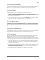
2.8.3 Optional Computer Gateway CLI I/O
The optional computer gateway adds one or two connections to a host computer.
1. Remove the rear center-section cover of tower #2 and connect the computer cable
(503790-xxx) to JA of the CLI I/O board (see Figure 2-16). Use a small screwdriver to
tighten the screws (2) on the connector.
The tab number (-xxx) in the cable drawing number refers to its length in meters. The
maximum cable length is 305 meters (1000 feet).
80360230-001
I/O CLI
RS-449
JB
JA
Figure 2-16 — CLI I/O Board
2. If the host computer is running in a redundant mode, an additional cable must be
connected from the computer to JB of the CLI I/O board (see Figure 2-16). Use a small
screwdriver to tighten the screws (2) on the connector.
3. Using a cable-tie (51190879-001) on each cable, fasten the cables to their strain-relief
clamps (marked OPTIONS in Figure 2-7) on the lower transition panel.
Enhanced Micro TDC 3000 User’s Manual
2-20
9/95
2.8.4
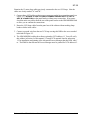
2.8.4 Optional Computer Gateway CLI/A I/O
The optional computer gateway adds one or two connections to a host computer.
Figure 2-17 and Figure 2-18 show the physical characteristics of the Computer Gateway
I/O board designed to follow the EMC Directive. The board design remains the same as the
old version. A bulkhead face plate is added to the PWA and supports the two D-type
connectors. The cables are changed to braid over foil shield with 360 degree metalized
plastic back-shells.
JB
RS-449
JA
53371
ASSY NO. 80360230-001
REV G
BAR CODE
Figure 2-17 — CLI/A Face Plate
JB
JA
53404
Figure 2-18 — CLI/A I/O Board
Enhanced Micro TDC 3000 User’s Manual
2-21
9/95
2.8.5
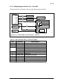
2.8.5 Optional EPLC Gateway
The optional Enhanced Programmable Logic Controller Gateway (EPLCG) allows
connection to various Programmable Logic Controllers. You must configure your EPLCG
and prepare the other end of the RS232 cable(s) according to the PLC (and modem) you are
using. Refer to the EPLC Gateway Planning, Installation & Service manual in the
Implementation/EPLC Gateway binder and the manuals with your PLC for more detailed
information.
1. Remove the rear center-section cover of the tower and check that the pinning header is
plugged into the OTHERS socket near the top right side of the PLCG relay panel (refer
to Figure 2-19).
2. Connect the PLCG RS232 cable (51304514-100) to either PORT 1 or PORT 2 on the
PLCG relay panel (see Figure 2-19). Use a small screwdriver to tighten the screws (2)
on the connector.
OTHERS REDUNDANT
A-B
J2A
PORT 1
PLCG RELAY PANEL
PORT
CONNECTIONS
PORT 2
J2B
51304421-100
Figure 2-19 — PLCG Relay Panel
3009
3. An additional cable may be connected to PORT 2 or PORT 1 (see Figure 2-19) if your
PLC configuration uses it. Use a small screwdriver to tighten the screws (2) on the
connector.
4. Using a cable-tie (51190879-001) on each cable, fasten the cables to their strain-relief
clamps (marked OPTIONS in Figure 2-5 or 2-7) on the lower transition panel.
Enhanced Micro TDC 3000 User’s Manual
2-22
9/95
2.9
2.9 OPTIONAL LCN UPGRADE
The LCN upgrade kit can connect a base Enhanced Micro TDC 3000 systems into a standard
LCN system. There are 6 different LCN upgrade kits: one to accommodate either 5 or 7
empty chassis for nodes to be moved into. The installation process is fairly involved in that
those nodes not associated with the Universal Station node will have to be moved from the
Enhanced Micro TDC 3000 towers to individual 5-slot modules located in an LCN cabinet.
The 5-slot modules in the cabinet come equipped with a power supply and fan mounted in the
cabinet and coax cabling already assembled.
The History Module Drive must also be removed from the Enhanced Micro TDC 3000 and
reassembled in the WDA Module located in the cabinet.
Up to two Universal Station (US) nodes may remain in the Enhanced Micro TDC 3000 to
function with the coax interface, but must be relocated to appropriate slots. (Additional USs
will each require an additional Enhanced Micro TDC 3000 tower with multinode module and
power supply.) The remaining slots can no longer be used and blocking panels are included
with the upgrade kits. LCN coax connections from the console to the LCN cabinet and the
cabinet to the LCN system must then be performed. Different configurations are allowed for,
but there are a number of constraints to keep in mind. These constraints are listed in the
upgrade kit instructions.
Finally, you will need to reassign node numbers in the Enhanced Micro TDC 3000 to ones
that are compatible with the LCN system. Node reassignment is described in LCN Guidelines
- Implementation, Troubleshooting, and Service in the LCN Installation binder. Detailed
directions for performing this upgrade can be found in the MX-ZUKB50, 51, 52, or MXZUKB70, 71, 72 Upgrade Kit Installation Instructions. The instructions you receive with the
upgrade kit will depend on the number of nodes being upgraded.
Enhanced Micro TDC 3000 User’s Manual
2-23
9/95
2.10
2.10 INSTALLATION WRAP-UP
1. Check to see that all signal cables and coaxial cables entering towers are properly
secured to the rear of the towers by strain-relief clamps or connector screws. Install the
rear covers with star washers on both towers.
2. If you have not already done so, dress signal and power cables neatly, at the rear of the
system, so that they will not be a personnel hazard. Dress cables that leave the area to
connect to UCN taps, etc., so they will not be stepped-on or damaged in any way.
3. Gather packing material, boxes, and pallets and remove them from the operations room.
Temporarily store the shipping boxes in the event something must be returned to the
factory.
4. Clean and tidy the operations room to keep operating media (cartridge disks) from
being unduly exposed to dust and foreign material.
5. Check each cartridge slot of the cartridge drives. If there are polystyrene shipping
inserts in the slots, carefully remove them.
6. Make sure the power switches on both towers, the color monitor(s), and the printer are
all OFF.
7. Plug power cords from all units into the proper receptacles for the power required.
8. Continue on to Section 3 for power-up tests and other checkout procedures.
Enhanced Micro TDC 3000 User’s Manual
2-24
9/95
3
CHECKOUT
Section 3
This section tells you how to check the Enhanced Micro TDC 3000 Control System after it has
been installed, plugged in and is ready to go.
3.1 POWER-ON TESTS
Do not perform any of these tests until the Enhanced Micro TDC 3000 Control System has
been installed according to Section 2. Check that the rear panels on the towers have been
installed and all signal cables and power cords connected. See that the area is cleared of
packing material and other installation debris, and the area is clean. Check that all power
switches are off.
You will now perform a series of checks and tests to insure the equipment is working. If
any of the tests are not met, refer to Section 6, Service.
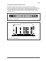
3.1.1 Tower #1 Electronics Checks
Tower #1 is the tower on the right with two black cartridge drives in the upper left corner.
1. Use both hands to remove the front panel from tower #1 by grasping the edges of the
panel near the bottom and pulling the panel straight out. Spring-loaded catches on each
side of the panel disengage, and the panel may be removed by pulling it out and down.
Be careful not to damage the cartridge drives when removing the panels.
NOTE
The front panels of the towers may be removed or replaced while power is on because
there are no lethal voltages exposed. Of course, observe caution with metallic objects
because the equipment may still be damaged if low voltages are shorted.
2. You now have access to the front of the Multinode Module in tower #1. Locate the
power switch (see Figure 3-1). Before turning power on, ensure the LO-NOM-HI
jumper just below and to the right of the power switch is set in the NOM or center
position. This is a maintenance jumper that is not to be changed by the user.
3. Compare your module with the Figure 3-1 illustration. Note the module contains four
nodes and each node has a processor board in the first board slot and a personality or
peripheral board in the second slot. Nodes have unique numbers from 1 to 8 (not A,
B, C, D as in the figure) and are factory set. You will identify the node numbers in an
upcoming test. Other board slots may or may-not contain boards, therefore, are shown
shaded. Note a horizontal row of green LEDs along the bottom, with another row of
either yellow or green LEDs just above them. Note each processor board contains a
display containing several red LEDs and a red alphanumeric status display.
Enhanced Micro TDC 3000 User’s Manual
3-1
9/95
3.1.1
Fan Assembly
ON
10
9
8
7
6
5
4
3
2
1
Fan Alarm LED
Power
Supply
LO-NOM-HI
Jumper
Alphanumeric
Status Displays
Reset
Switch
Red LEDs
Green LEDs
Power OK
Error
Yellow or
Green LEDs
Nodes- D
C
B
A
53287
Figure 3-1 — Typical 4-Node Tower Electronics—Front View
Enhanced Micro TDC 3000 User’s Manual
3-2
9/95
3.1.2
4. Now initiate power-up tests on tower #1 by setting the POWER switch to ON. The red
LEDs on the boards light for a few seconds (it takes less than 30 seconds to complete
the power-up tests), then they turn off and the green LEDs turn on. If any red LEDs on
the boards remain on, some portion of the power-up tests have failed—record the
alphanumeric status display code and proceed to Service, Section 6 in this manual.
If the power-up test is successfully completed for all nodes, all green LEDs on all
boards are on (there may also be some yellow LEDs on or flashing), and the
alphanumeric status display indicates the node address (ranging from 1 through 8) for
each of the nodes. Temporarily record these three node numbers.
5. Check the power supply status LEDs (POWER OK and ERROR) and the FAN ALARM
LED. Note the FAN ALARM and ERROR LEDs are off and the POWER OK LED is on (it
is a fault condition if both the ERROR and POWER OK LEDs are ON).
6. Press the momentary RESET switch. Note the power-up tests are initiated similar to
step 4, and the results are satisfactory.
7. Replace the front cover on tower #1 by holding the cover with both hands and catching
the top of the cover into the lip at the top of the cabinet. Be sure the sides of the cover
are on the outside of the cabinet. Now swing the bottom of the cover into place,
pressing firmly on the bottom until the cover is secured by both spring-loaded catches.
3.1.2 Tower #2 Electronics Checks
Tower #2 is similar to tower #1, but it has a 512 MB hard disk drive where the cartridge
drives are located in tower #1 (but the hard disk drive is normally hidden by the front
panel). Note the Multinode Module in tower #2 may not be as completely filled with nodes
as it was in tower #1.
1. Now repeat all the tests in subsection 3.1.1 again on tower #2.
NOTE
Your system has already been shipped with bootload software (Directory & LDR) installed on
the Winchester disk drive. The HM (History Module) automatically boots its node after powerup tests in this tower have finished.
It is OK to press the RESET switch or turn the power off in the middle of this automatic
bootload because there is no write activity to the drive at this time. However, in an operating
system, NEVER press the RESET switch if there is a possibility of a write-in-process. Please
note the HM automatically boots every other time the RESET switch is pressed.
2. Note the node numbers used in tower #2 are different from the node numbers you
found in tower #1. Temporarily record these node numbers. Now compare all of your
node numbers with Table 6-1 in Section 6 of this manual and verify you have the
correct node types.
Enhanced Micro TDC 3000 User’s Manual
3-3
9/95
3.1.3
3.1.3 Color Monitor Check
1. Set the color monitor power switch to ON. On the front of the 20" monitor, beneath
the bezel, the pushbutton to your right is the Power ON/OFF switch. The left
pushbutton is for degaussing. The power switch on the 21" monitor is located at the
right front of the monitor, just below the display screen.
2. Adjust brightness for best resolution on the blinking character that appears on the upper
left side of the screen. On the front of the monitor, beneath the bezel, the left
thumbwheel is the Brightness control. The right thumbwheel is the Contrast control.
3. Position (tilt) the screen display for comfortable viewing.
3.1.4 Printer Checks
These tests are only initiated when power is first turned on, therefore, always start the tests
with power OFF. The power switch is at the rear of the printer, just above the line cord.
Run both of these printer tests after initial installation. Also run the self-test any time a new
ribbon or print head has been installed on the printer. Inspect the self-test printout carefully
to insure high quality print copy from your printer.
Run the user diagnostic test whenever you suspect a malfunction in the printer electronics.
Table 3-1 shows the states of the printer display while in normal operation and when the
tests are run. If these tests do not run satisfactorily or if the user diagnostic test does not
finish, consult Service, Section 6, in this manual.
3.1.4.1 Printer Self-Test
1. Ensure that there is ribbon and paper in the printer, and that the top cover is closed.
2. Press and hold the ON LINE button while setting the POWER switch to ON, then release
the ON LINE button.
3. The printer display first shows ASPI, then the printer begins its self-test, printing a full
line of characters, time-after-time, advancing one character at the beginning of each line
until the full character set is printed. While printing the self-test, the printer display
shows TEST. The test continues indefinitely.
4. Press the ON LINE button to stop printing. The printer shows WAIT. Press the ON LINE
button again and the printer displays LINE. It is then on-line.
Enhanced Micro TDC 3000 User’s Manual
3-4
9/95
3.1.4
Table 3-1 — States of ASPI-41 Printer Display
NORMAL OPERATION
Turn power on
ASPI
LINE
Display when turned on.
On-line—ready to print.
SELF-TEST
Hold ON LINE button while you turn power on
ASPI
TEST
WAIT
LINE
Display when turned on.
Continuous pattern printed.
• (Press ON LINE button here)
Off-line—waiting.
• (Press ON LINE button here)
On-line—ready to print.
USER DIAGNOSTIC TEST
Hold
ASPI
BBBB
*BBB
**BB
***B
****
T&D1
T&DT&DG
A 41
T&DH
LINE
T&DI
?END
ASPI
LINE
button while you turn power on
Display when turned on.
Start of test (“B” signifies a “box” is being displayed).
Test cycles through four states.
Sequences from test “1” through test “G.”
Display is flashing—Printer identifies itself.
Test H.
Configuration is printed (see Figure 3-2).
Test I.
End of T&Ds—waits 5 seconds to see if you want to start again.
No—T&Ds are off.
On-line—ready to print.
Enhanced Micro TDC 3000 User’s Manual
3-5
9/95
3.1.4
3.1.4.2 Printer User Diagnostic Test
1. Hold the
button while turning the printer ON. Several tests are run and their results
displayed. The steps which follow tell what the various displays will look like. Since
their are no pauses between tests, you may need to run this test more than once.
2. The display will show a sequence of 4 boxes, then 3, 2, and so on until none are
displayed. Each box is replaced with an asterisk.
3. The letters T&DX are then displayed, where X is a sequence of numbers and letters as
various Tests and Diagnostics (T&Ds) are performed. After T&DG is displayed, the
printer flashes A 41, indicating it is an ASPI-41 printer. It then completes the T&D
tests with T&DH, goes on LINE, and prints its User Test configuration which looks
something like Figure 3-2.
4. The test finishes with test T&DI, then displays ?END for about 5 seconds. The display
then cycles to ASPI, then LINE, and is ready to print.
5. If you wish to continually run through the diagnostic tests, press
during the time
?END is being displayed. Most likely, if one of the diagnostic tests fails, it will stop
while displaying a T&DX figure. Record the number or letter represented by X before
proceeding to service it.
ASPI 40/41 Printer
USER TEST
Configuration: epr=W1302
sio=Y0126
Figure 3-2 — Printer User Diagnostic Test Message
Enhanced Micro TDC 3000 User’s Manual
3-6
ocg= free
asf= no
3011
9/95
3.1.5
3.1.5 Cartridge Drive Checks
1. First, select a cartridge and check that the protect switch is in the WRITE PROTECT
position (see Figure 1-4) on the cartridge.
2. Drive power is supplied by the tower #1 power supply. If power is off, the latch pin in
the drive prevents cartridge insertion. Carefully insert the cartridge in the drive loading
slot (see Figure 1-4). Note the green LED on the drive blinks for 5 to 10 seconds while
the disk comes up to speed, then goes on steady as the yellow LED flashes (only once
at this time) to indicate drive access. The green LED remains on steadily as long as the
cartridge is in service. The yellow LED will flash periodically when software writes or
reads the disk in the future, but the period of the flash will be very brief.
CAUTION
DON'T attempt to remove the cartridge from the drive while the green LED is ON or BLINKING.
Also, DON'T attempt to move the protect switch on the cartridge while the cartridge is installed
in the drive.
Serious damage may result to the cartridge or the drive if these cautions are not heeded.
3. When you wish to remove the cartridge, press the stop button on the drive and note the
green LED blinks for several seconds, then goes off. Only then may you safely
remove the cartridge.
3.2 SYSTEM CHECKOUT WRAP-UP
If your equipment passes the checks and tests in this section, proceed to the Implementation
and Operational Guidelines, Sections 4 and 5. If not, correct the problem by referring to
Service, Section 6 of this manual or consult your Honeywell representative.
Enhanced Micro TDC 3000 User’s Manual
3-7
9/95
Enhanced Micro TDC 3000 User’s Manual
3-8
9/95
4
IMPLEMENTATION
Section 4
This section guides you though the configuration and data-entry process for the Enhanced Micro
TDC 3000 system. If you are familiar with the Engineering Personality functions, you may be able
to implement your system with little or no reference to the standard LCN bookset, but in case you
need them; references are provided to the binders and publications that contain the detailed
implementation references and instructions.
4.1 IMPLEMENTATION OVERVIEW
The Enhanced Micro TDC 3000 systems consist of a limited set of equipment and
functions, so the range of implementation tasks is reduced to those supported by the
purchased equipment and options. Therefore, in this implementation section, we describe a
predetermined set of implementation choices and values, some of which are fixed by the
characteristics of the Enhanced Micro TDC 3000 system (for example, node numbers and
node-pair numbers), but most of which you can change to suit your application.
4.1.1 Database Configuration
The following example Enhanced Micro TDC 3000 system databases are described in this
section:
•
Network Configuration—Network Configuration File (NCF)
•
UCN/APM Box Points and Data Points—Parameter values for UCN and APM Box
Point parameter values, which must be built and loaded before data points can be
built.
•
Area Database Configuration—Area database
4.1.2 The Implementation Process
“Implementation” includes the individual startup of the system, as described under 4.2, and
the configuration and entry of the remaining data that defines data points, pictures
(schematics), buttons, Free Format Logs, and user-written programs. You can load all or
part of the prebuilt files or configure the entire system yourself.
For a quick overview of the implementation process, refer to Implementation Overview in
the Implementation/Startup & Reconfiguration - 1 binder. For additional definition and
guidance, see Configuration Data Collection Guide in the Implementation/Startup &
Reconfiguration - 2 binder.
Enhanced Micro TDC 3000 User’s Manual
4-1
9/95
4.2
Detailed configuration and data entry instructions applicable to the Enhanced Micro
TDC 3000 system are in the following binders:
•
Implementation/Startup & Reconfiguration - 1/2/3
•
Implementation/Engineering Operations - 1/2/3
•
Implementation/Application Module - 1/2/3
•
Implementation/Advanced Process Manager - 1/2
4.2 SYSTEM STARTUP
If you have the standard system: an AM, one or two NIMs, one or two Universal Stations,
and a standard double-sided APM cabinet, you may want to skip any configuration
changes, load the standard prebuilt files, and go right into the Universal Personality. If so,
skip this section and go to subsection 5.1.1.1, How To “Bootload” US 1 with the
Universal Personality from a Pre-Loaded HM.
Follow the procedures in this section—
•
•
•
•
•
if the system has an optional CG or EPLCG
if you want to make configuration changes
if boards were added to the standard APM cabinet (see Chart 4-1)
if the system has a nonstandard APM cabinet (see Chart 4-1)
if you just want to learn about the configuration process,
Prebuilt files are supplied for the Local Control Network (LCN) including the AM and
NIM, one Area, and a few AM/APM points. Two Universal Stations and two NIMs are
included in the standard configuration but if only one of these pairs is actually present, the
other will show a status of OFF. Parameters in the prebuilt Local Control Network
configuration files (NCF) are shown in subsection 4.2.2. Parameters in the prebuilt data
points and configurable buttons are shown in appendices to this publication. Parameters in
the prebuilt Area Database are shown in subsection 4.8.2.
To make configuration changes, the Enhanced Micro TDC 3000 must have an Engineering
Keyboard connected to the station with the cartridge disk drives.
Selecting—In the pages that follow, when instructed to select something on the display, do
so by moving the cursor onto the target and then press the SELECT key on the appropriate
keyboard. If you have the optional touchscreen, touch the target to move the cursor onto
the target; the select is performed by removing your finger from the display. If you have
the optional trackball, position the cursor onto the target with the trackball and press the
select key on the trackball. When instructed to enter something, move the cursor
to the appropriate port, key in (type) the data, and then press the ENTER key on the
appropriate keyboard or on the trackball. In Section 4, use the Engineering Keyboard
unless otherwise instructed. On the trackball, the right-hand key is Select and the left-hand
key is the Enter key.
Enhanced Micro TDC 3000 User’s Manual
4-2
9/95
4.2.1
4.2.1 Local Control Network Configuration
You can load the prebuilt file or configure the entire network yourself. The following
questions will help you pick the next step.
NCF Configuration Questions—
1.
Does this system have a Computer Gateway (CG) or Enhanced Programmable Logic
Controller Gateway (EPLCG)?
• Yes - go to step 2
• No - go to step 4
2.
Do you want to load the prebuilt LCN Network Configuration file and add the
EPLCG or CG node later with a procedure called On Line Network Configuration?
You should have some experience with the LCN file system to do this?
• Yes - go to step 5 Watch for EPLCG/CG notes in the procedures.
• No - go to step 3
3.
Follow instructions in the System Startup Guide—Cartridge Drive, in the
Implementation Startup & Reconfiguration - 1 binder to configure the system.
Instructions for a first-time start up of any LCN-based TDC 3000X system, including
the Enhanced Micro TDC 3000 system, are provided to take you step-by-step
through a first-time startup of a system that has no database. The procedures include
the building, loading, and installing all data needed to attain a minimum operating
system on which you can build the remainder of your system- and process-related
data.
NOTE
When the System Startup Guide is used to configure a system:
Performing certain procedures will overwrite standard software that was shipped
on the History Module (CG and EPLCG software is not on the HM anyway; this software is on
the cartridges).
A EPLCG is configured as a subset of the Hiway Gateway, therefore, follow the
instructions for an HG configuration except where noted and refer to the HG Forms and HG
manuals. You must configure an HG node in Task 9 and load &HGO and &HGG software in
Task 16.
4.
Do you want to load the prebuilt LCN network configuration file? If you are not
familiar with the configuration process, this is the fastest way to get a station running
the Engineering Personality. You can reconfigure the system later.
• Yes - go to step 5.
• No - go to step 2 in 4.2.1.1.
5.
Follow the instructions in subsection 4.2.1.1 to load the prebuilt network
configuration file (NCF).
Enhanced Micro TDC 3000 User’s Manual
4-3
9/95
4.2.1
4.2.1.1 Loading Prebuilt Network Configuration Data
In the steps that follow, you will load US 1 with the Universal Personality and the prebuilt
NCF file. The Universal Personality allows you to switch quickly between the Operator’s
Personality and the Engineering Personality. The Engineering Personality is used to
configure the system or to change system configuration.
1. If not already off, turn off the power switch on tower 1 (the right tower) and on
tower 2 (the left tower) for a few seconds and then back on. Loss/return of power
in tower 2 resets the node(s) and forces the HM to autoboot. Loss/return of power
in tower 1 resets the nodes in that tower. Wait for > to appear in the upper left
corner of the screen of the monitor connected to tower 1.
2. On the Operator’s Keyboard, press LOAD. N,1,2,3,4,X appears.
3. On the Operator’s Keyboard, press the ALPHA SHIFT key (until the indicator
comes on), key in N, then press ENTER. Several messages appear, ending with
OPR, UNP?
4. On the Operator’s Keyboard, key in UNP and press ENTER.
5. Wait a few minutes for the System Status display to appear. Press CTRL/HELP on
the Engineering Keyboard to go to the Engineering Main Menu.
6. The Engineering Main Menu should be on the screen. On the Engineering
Keyboard, press PF1. Enter the schematic name KEYLOCK and press ENTER.
Select the ENGR target. For more information on how to use the access keylock,
refer to subsection 5.3.3, Keyswitch Access Levels .
Set the Time and Date—
7. Select the SYSTEM STATUS display target on the Engineering Menu. On the
System Status display, select the TIME/DATE target.
8. When the TIME/DATE CHG targets appear, select the DATE CHG target. Key in
the current day, month, and year (for example, 15 MAR 92) and press ENTER.
The current date should appear in the upper right corner of the display.
9. Select the TIME CHG target and then key in the time in hours and minutes (for
example, 14 25). Press ENTER and the current time should appear in the upper
right corner of the display.
Enhanced Micro TDC 3000 User’s Manual
4-4
9/95
4.2.1
Check HM Operation—
10. On the Operator’s Keyboard press the SYSTEM STATUS key. On the System
Status display, select the HM Node Object Box, then select the NODE STATUS
target.. If the HM status is anything other than OK, you should not continue until
the problem is fixed. For information on how to use the “Load_HM.EC” file on
&C8, refer to Sections 13 through 17 in the System Startup Guide - Cartridge
Drive, in the Implementation/Startup & Reconfiguration - 1 binder.
If the status is OK, and you want to check the contents of the HM, do the
following—
On the Engineering Main Menu, select COMMAND PROCESSOR.
Key in the command LSV NET. Press ENTER. The resulting output on the
screen should appear similar to Table 4-1. Table 4-1 shows all volumes and
directories on the HM. You may not have them all. For example, &CGO and
&HGO are optional Computer Gateway and Hiway Gateway programs.
4.2.1.2 Network Configuration Completion
At this point the Local Control Network is configured with the prebuilt NCF file. You can
browse through the items on the left column of the Engineering Menu if you like by
selecting the targets one at a time. Some of the configuration displays have several pages.
Use the PAGE FWD and PAGE BACK keys to see all pages. Return to the Engineering
Menu by pressing CTL/HELP after looking over each item. Refer to the subsection 4.2.2
for a listing of the prebuilt NCF file.
Optional EPLCG or CG—
If the system has an optional EPLCG or CG node, you can add either or both to the
network with the On-Line Reconfiguration procedures described in Section 7 of the
Network Data Entry manual. When a EPLCG or CG node is added to the network, it
must be loaded with its Operator Personality. You will want to have these personalities
on the HM, however, they are not preloaded like the others and all HM space is
allocated. Solution: the existing HM volume named PICS is large enough to hold this
software. Create directories for the files you need to load (e.g., &HG0, &HGG, and/or
&CI0). Refer to Section 16 in the System Startup Guide—Cartridges, for loading
procedures and Section 18 to load the Operating personality into the node(s). Note that a
EPLCG is configured as a subset of the Hiway Gateway node.
The next step is to load the Gateways and Modules (subsection 4.3).
Enhanced Micro TDC 3000 User’s Manual
4-5
9/95
4.2.1
Table 4-1 — System Volumes and Directories
Volume
Directories
Volume Use
&001
&ASY, &DSY, &HGG, &NMG &AMG,
&ARG, &KFO, &LDR
System files
&101
&OPR, &ENG, &UNP, &OV1, &OV2,
&OV4, &OP1, &OP2, &OP4, &AMO,
&CIO, &NMO, &PMO, &LMO
Personality load images
&PIO, &ALO, &APO?
&201
&AMD, &CGD, &HGD, &HMD,
&OPD, &PMD, &NMD, &LMD
Dump volume
&PID, &ALD, &APD?
&301
&D01
Area database
&501
&Fun (100), &Z05 (Note 1)
AM checkpoint
&801
&I01
NIM/PM checkpoint
&901
&E01, &L01
CL/PM Sequences
!001
!Aun (100) (Notes 1 and 2)
Continuous history
!201
!CSY, Cun (100) (Note 1)
Journal manager, journals
!401
!ESY
On-proc. analysis, maint. support
PICS
Schematics
CL
CL Programs
TEST
User files
CDSG
Custom Data Segments
Key:
an = area number
hn = UCN number
un = unit number
Note 1: The numbers in parenthesis indicate the maximum number of each type of directory per system.
Each volume can have no more than 63 directories of any type.
Note 2: The total number of &Aun directories cannot exceed 100.
Note 3: The HM personality images are not in volume &1np. They are &HMI (initialization personality)
and &HMO (on-line personality), which are provided on floppies or cartridges and are copied to each
HM's Local Volume (!9np). &HMI and &HMO don't exist as directories on the LCN. Only HMs use &HMI
and &HMO and only out of their own Local Volume, not across the LCN.
Enhanced Micro TDC 3000 User’s Manual
4-6
9/95
4.2.2
4.2.2 Prebuilt Network Configuration Data
The following data shows entries in the prebuilt NCF file. This data is shipped as file
NCF.CF on volume &ASY in the History Module and on cartridge &C8.
Units, Unit Names
10 Units,UNIT 1 through UNIT 10
Area Name - Area Description
AREA01 - AREA01
AREA02 - SPARE
Console Number, Console Description
LCN Nodes
1, MICRO TDC 3000
US: 1
US: 2
NIM: 3 (Primary)
NIM: 4 (Secondary)
AM: 5
HM: 6
CG: 7
US: 8
Universal Stations
Node
Consloe #
Station #
Default Area
Cartridge Drives
Printer Number
Default Access Level
Oper Kbd
Touch Screen
Engr Kbd
1
1
1
AREA01
1 & 2
1
OPER
YES
YES
YES
Node
Consloe #
Station #
Default Area
Cartridge Drives
Printer Number
Default Access Level
Oper Kbd
Touch Screen
Engr Kbd
2
1
2
AREA01
NONE
NONE
OPER
YES
YES
YES
Node
Consloe #
Station #
Default Area
Cartridge Drives
Printer Number
Default Access Level
Oper Kbd
Touch Screen
Engr Kbd
8
1
4
AREA01
NONE
NONE
OPER
YES
YES
YES
Enhanced Micro TDC 3000 User’s Manual
4-7
9/95
4.2.2
Application Module
Node
5
HOT
02, 04, 06, 08
Startup Mode
Assigned Units
History Module
Node
Node Pair No.
6
1
Network Interface Modules
Nodes
Process Network (UCN) No.
3 & 4
1
Computer Gateway
Node
Startup Mode
Assigned Units
7
Hot
01, 03, 05, 07, 09
System Wide Values
System ID
System Descriptor
System ID
MICRO TDC 3000
TDC
Clock Source
Clocks located in nodes 5&6
User Average Period
10 minutes
Shift Data
Shifts per week
Monthly period type
Report starts hour + day of week
Shift starts
Each shift length
21
CALENDAR
0
MON
1
MON
8 hours
Console Data
NCF Source
Fast/raise/lower rate
Printer page length
Printer page width
Trend pen delay
CL message Confirmation after
acknowledgement
Printed trend format
Real Time Journal size
Real Time Journal Header/Trailer
messages
Contact Cutout Alarms on Alarm
Summary
Enhanced Micro TDC 3000 User’s Manual
NCF>&ASY>NCF.WF
5 PERCENT PER INCREMENT
66
132
1 SEC
NO
GRAPHIC
100
BEG/END
CLEAR WHEN ACKNOWLEDGED
4-8
9/95
4.2.2
Horn Annunciator Policy
Console Status Event
System Status Event
Operator Ack Only Message
Operator Confirm Message
Low Priority Alarm
High Priority Alarm
Emergency Priority Alarm
Contact 1 Output State
Contact 2 Output State
Contact 3 Output State
CONTACT_1
CONTACT_1
CONTACT_1
CONTACT_2
CONTACT_1
CONTACT_2
CONTACT_3
STEADY
STEADY
STEADY
Alarm Management Configuration
Red Color Alarm Priority
Priority Indicators On Alarm Displays
Three Color Alarm Priority
Emergency
High
Low
Low Priority Alarms in Alarm
Summary
Initial Alarm Summary Sort State
Audible Alarm Annunciator
Suppression Rime-out (seconds)
Alarm Summary Freeze Time-Out (Sec)
Area-Based Process Alarm Ack?
EMERGENCY
CHARACTERS
RED
YELLOW
MAGENTA
NO
PRIORITY
0
0
NO
Alarm Command Access Table
Change Alarm Summary Sort State
Chg Alarm Priority Filter on Alarm
Summaries
Chg Audible Alarm Annunciation
Suppression
Alarm Summary Display Freeze
Enhanced Micro TDC 3000 User’s Manual
OPER
OPER
OPER
OPER
4-9
9/95
4.2.2
Physical Node Command Access Table
Load Operations Non US NOde
Load Operation Local Console US
Load Operation Remote Console US
Dump Node
Override Dump
Shutdown Node
Override Shutdown
Enable/Disable Load/Dump
Change Time or Date
Change Area
Override Change Area
Change ALENBST
Idle Process Manager
Demand Checkpoint Node
Enable/Disable Auto Checkpoint
Switch Primary to Secondary
Override Switch Primary to Secondary
Enable/Disable History Collection
Hot/Warm/Cold/On-Process Start AM
Warm/Cold Start HG
Printer Assignment Change
Clear Maintenance
Load Test
Load Init
No Point Access Load
Command Load of Process Gateway
Node
Command Restore of Process Network
Devices
Commaand Load of Process Network
Devices
Command Checkpt of Proccess
Network Devices
OPER
OPER
SUPER
OPER
OPER
SUPER
ENGR
SUPER
OPER
SUPER
SUPER
ENGR
OPER
OPER
SUPER
OPER
SUPER
OPER
OPER
ENGR
OPER
SUPER
SUPER
ENGR
ENGR
OPER
OPER
OPER
OPER
Miscellaneous Commands Access
Sequence Command Load Program
Sequence Command Save Program
Box Variable Change Access
System Event Acknowledge Access
Floppy Init Access
Access Lvl to Change View Access
Access Lvl to Chng Unit Assignment
Access Lvl to Chng Unit Deassign
Access Lvl to Chng Unit Alarm Enable
Access Lvl to Chng Unit Alarm Disable
Access Lvl to Chng Unit Alarm Inhibit
Process Network Fast Commands
Software Option Key File
Enhanced Micro TDC 3000 User’s Manual
OPER
ENGR
ENGR
OPER
SUPER
SUPER
OPER
SUPER
OPER
SUPER
SUPER
OPER
HG POINT DISPLAY RANGES
ENHANCED TREND PENS
HM DISK REDUNDANCY
PRINTED SUMMARIES
4-10
9/95
4.2.2
Volume Configuration
Node Pair Number
Number of Winchester Disks
Disk Type/Size
HM Init Personality?
System Volume?
GDF Files Included?
File Manager Descriptors?
Area SOE Journal Size
Burst Buffer Size (For Process/System
Journals)
System Unit Journals?
Status Change
Error
Maint
1
1
6
YES
YES
YES
NO
3750
4000
Select Volumes for This HM
PROGRAM IMAGE
AREA
CHECKPOINT
CONTINUOUS HISTORY
JOURNALS
CL STORAGE
USER FILE STORAGE
YES
4096
4096
2048
Program Image Volume Configuration
Personalities Selected
CM II,HG II,AM II,USOPR II,
USUNPII,NIM II,NG II
CM IV,HG IV,AM IV,USOPR IV,
USUNP IV,NIM IV,NG IV
Dump Volume Size (KB)
18000
Area DataVolume Configuration
Area Name
Volume Size (KB)
Number Files
AREA 01
5000
500
Physical Node for Checkpoint
Configuration
Node 3 (NIM)
Node 4 (NIM)
Node 5 (AM)
Node 7 (CG)
20000
0 kb,
10000
10000
Continuous History Groups Configuration
Unit IDs
Groups per Unit
1 - 10
10
Enhanced Micro TDC 3000 User’s Manual
4-11
kb, 100 files
0 files
kb, 100 files
kb, 100 files
9/95
4.2.2
Continuous History Group Options
Unit IDs
Groups per Unit
Save Options
Snapshot Hours
User Avg Hours
Archive
1 - 10
10
SNAPSHOTS & USER AVG
168
336
NO
Process Unit Journal Configuration
Unit IDs
Process Alarms
Process Changes
Operator Messages
1 - 10
6000
6000
1000
CL Storage Volume Configuration
Hiway Network (UCN)
Number of Files
Volume Size (kb)
1
99
20000
User File Storage Configuration
Volume ID - PICS
Volume ID - CL
Volume ID - TEST
5000 Files, 200000 kb
5000 Files, 150000 kb
5000 Files, 150000 kb
Enhanced Micro TDC 3000 User’s Manual
4-12
9/95
4.3
4.3 LOAD GATEWAYS AND MODULES
The following steps load the modules (nodes) with their operating personalities. The HM
also contains prebuilt data for the Enhanced Micro TDC 3000 configuration. You are
given the option to select blank (null) files as each module is loaded. Subsection 4.3.1
shows the preconfigured NIM data.
4.3.1 Loading the AM
1. On the Operator’s Keyboard, press the SYSTEM STATUS key. On the System Status
display, select the AM Node Object Box, then select the NODE STATUS target.
2. On the Application Modules Node Status display, select the AM node number (05).
3. When the Node Load targets appear, select the MANUAL LOAD target .
4. Select a load option (e.g., COLD LOAD).
5. When the Program Source target appears, select DEFAULT SOURCE. Then select the
EXECUTE COMMAND target.
6. When the Data Source target appears, select DEFAULT SOURCE, and then select the
EXECUTE COMMAND target. Press the ENTER key to start loading. In a few
minutes the AM status should change from LOAD to OK. Note that because the AM
checkpoint is on the HM, one prebuilt AM point is loaded. If you do not want to load
that point, you may choose ALTERNATE SOURCE for the Data Source and read the
null checkpoint from cartridge &C8. The prebuilt points are described in Appendix A
of this manual.
4.3.2 Loading the NIM
1. On the Operator’s Keyboard, press the SYSTEM STATUS key. On the System Status
display, select the NIM Node Object Box, then select the NODE STATUS target.
2. On the Process Networks Node Status display, select the primary NIM node number
(03).
3. Select the LOAD/DUMP target.
4. When the Node Load targets appear, select MANUAL LOAD target.
5. When the Load Option targets appear, select OPERATOR PROGRAM.
6. When the Program Source target appears, select DEFAULT SOURCE. Then select the
EXECUTE COMMAND target. The Data Source display appears.
7. On the Data Source display, select DEFAULT SOURCE; then select the EXECUTE
COMMAND target. Press ENTER to start loading. In a few minutes the NIM status
should change from LOAD to OK.
If you do not want to load the preconfigured data, you must use a null checkpoint as
the data source. The null checkpoint is on cartridge &C8. Insert cartridge &C8. When
prompted for the Data Source, choose ALTERNATE SOURCE and then select the
drive number that contains &C8. Use the procedures in Section 32 of the System
Startup Guide—Cartridges to configure the NIM.
Enhanced Micro TDC 3000 User’s Manual
4-13
9/95
4.3.2
8. If the System has an optional redundant NIM, it is loaded in a similar way except
choose node 04.
4.3.2.1 NIM Prebuilt Configuration Data
These entities define the primary NIM as node 01 and the redundant NIM as node 02 on
process network 01 (the UCN). $NM01N01 specifies that NIM 1 when operating as the
primary NIM, has responsibility for control, parameter fetching and storing, alarming, and
checkpointing and that data is to be loaded in both the NIM and the APM. A similar entity
is built for the optional, secondary NIM if it is present. This data is in the checkpoint for
the NIM and was loaded when you specified the Default Data Source.
Parameter
(Name)
NTWKNUM
NODENUM
NODETYP
NODASSN
LOADSCOP
Description
Entity name
Network number
Node number
UCN Node type
Node assignment
Load scope
Value, Primary NIM
$NM01N01
01
01
NIM
ThisNIM
NIMandPM
Value, Sec. NIM
$NM01N02
01
02
NIM
ThisNIM
4.4 LOAD THE ADVANCED PROCESS MANAGER
The instructions that follow assume that the NIM was loaded in a preceding section and has
a status of OK. Power must be on at the APM cabinet. If you are not using a standard
APM cabinet as described in Chart 4-1, refer to Task 32 in the System Startup Guide, for
the procedures to build new IDFs and load the APM. If there were minor changes or
additions to the standard dual access APM cabinet, you may wish to reconstitute the
appropriate entities, change them and load them. Refer to the Data Entity Builder Manual,
for the procedures.
4.4.1 Standard Double-Sided Nonredundant APM Cabinet
1. If the Engineering Main Menu is on the screen, select the SYSTEM STATUS target on
the Engineering Main Menu. If not, press the SYSTEM STATUS key on the
Operator’s keyboard.
2. On the System Status display, select network 1 (the box with UCN01 in it).
3. Select the NTWK/HWY STATUS target.
4. On the UCN Status display, select the target 03 APM. The selected target should fill
with color. The status must be ALIVE.
5. Select LOAD/SAVE RESTORE. The box should change to white.
6. Select PROGRAM LOAD, then select ENTER.
7. On the Program Source display, select DEFAULT SOURCE, then select EXECUTE.
The Data Source display appears.
8. On the Data Source display, select DEFAULT SOURCE, then select EXECUTE.
Loading should begin. In a few minutes, The APM status should change to IDLE.
Enhanced Micro TDC 3000 User’s Manual
4-14
9/95
4.4.2
9. On the UCN Status display, the target 03 APM should still be selected (filled with
color).
10. Select LOAD/SAVE RESTORE. The box should change to white.
11. Select RESTORE DATA; then select ENTER.
12. On the Restore UCN Node display, select DEFAULT SOURCE, then select
EXECUTE. When RESTORED is displayed, proceed to Step 12.
13. Select DETAIL STATUS. Check the boxes on the Detail Status display. For each
implemented IOP, a box should contain the IOP type (e.g., HLAI) and the word
IDLE.
4.4.2 Expanded Standard APM Cabinet
If you are configuring a double-sided nonredundant cabinet with added IOP cards, use the
procedure in 4.4.1, then reconstitute the entity $NM01B03 (refer to the Data Entity Builder
Manual for the reconstitute procedure). Add the extra I/O Modules to the configuration for
the cabinet. Load the data by pressing F12.
To configure any other APM cabinet, follow the procedures in Task 32 of the System
Startup Guide—Cartridge Drive.
4.4.3 UCN/APM Box Point Configuration Data
The following entity defines the primary Advanced Process Manager Module as node 03 on
process network 01 (the UCN). This checkpoint information was loaded as the Data
Source for the APM. A redundant APM is configured as node 04 but otherwise contains
default values.
Parameter
(Name)
NTWKNUM
NODENUM
NODETYP
NODASSN
MOVPVTXT
BADPVTXT
Description
Value, Primary APM
Entity name
$NM01N03
Network number
01
Node number
03
Node type
APM
Node assignment
ThisNIM
Moving text descriptor
Neither
Bad PV text
Both
The following entity defines the physical configuration of the Advanced Process Manager
and several key operational characteristics.
Parameter
(Name)
NTWKNUM
NODENUM
CTLOPT
NCTLSLOT
NPVSLOT
NLOGSLOT
NDCSLOT
Description
Value
Entity name
$NM01B03
Network number
01
Node number
03
Control option
On
Number of control slots
40
Number of PV slots
20
Nmbr. of Logic slots
25
Nmbr. of Digital Comp. slots 150
Enhanced Micro TDC 3000 User’s Manual
Parameter
NPMSLOT
NUMERIC
SCANRATE
PKGOPT
IOMFILEA
IOMCARDA
IOMTYPE
FAILOPT(n)
4-15
Description
Value
No. of Process Module Slots
30
No. Numerics in PM Box Pnt. 2047
Scan rate
Reg1Log1
PMM Packaging Option
Nonredun
IOP file number
(see chart)
IOP card number
(see chart)
IOP card type
(see chart)
Output failure option
Unpower
9/95
4.4.3
Chart 4-1 — APM Box Point I/O Chart (n = 1 through 40)
Double-Sided Cabinet, Nonredundant APM
IOP Number
IOMFILEA File No.
IOMCARDA Card No.
IOMTYPE(n)
Card Type
1
2
3
4
5
6
7
8
9
10
1
1
1
1
1
1
1
1
1
1
6
7
8
9
10
11
12
13
14
15
HLAI
AO
DI
DO
None
None
None
None
None
None
11
12
13
14
15
16
17
18
19
20
21
22
23
24
25
2
2
2
2
2
2
2
2
2
2
2
2
2
2
2
1
2
3
4
5
6
7
8
9
10
11
12
13
14
15
None
None
None
None
None
None
None
None
None
None
None
None
None
None
None
26
27
28
29
30
31
32
33
34
35
36
37
38
39
40
3
3
3
3
3
3
3
3
3
3
3
3
3
3
3
1
2
3
4
5
6
7
8
9
10
11
12
13
14
15
None
None
None
None
None
None
None
None
None
None
None
None
None
None
None
(continued)
Enhanced Micro TDC 3000 User’s Manual
4-16
9/95
4.4.3
Chart 4-1 — APM Box Point I/O Chart (n = 1 through 40) (continued)
Double-Sided Cabinet, Redundant APM
IOP Number
IOMFILEA File No.
IOMCARDA Card No.
IOMTYPE(n)
Card Type
1
2
3
4
5
1
1
1
1
1
6
7
8
9
10
HLAI
AO
DI
DO
None
6
7
8
9
10
11
12
13
14
15
16
17
18
19
20
2
2
2
2
2
2
2
2
2
2
2
2
2
2
2
1
2
3
4
5
6
7
8
9
10
11
12
13
14
15
None
None
None
None
None
None
None
None
None
None
None
None
None
None
None
21
22
23
24
25
26
27
28
29
30
31
32
33
34
35
3
3
3
3
3
3
3
3
3
3
3
3
3
3
3
1
2
3
4
5
6
7
8
9
10
11
12
13
14
15
None
None
None
None
None
None
None
None
None
None
None
None
None
None
None
36
37
38
39
40
4
4
4
4
4
1
2
3
4
5
None
None
None
None
None
Enhanced Micro TDC 3000 User’s Manual
4-17
9/95
4.5
4.5 LOADING THE EPLCG OR CG
If optional EPLCG or CG nodes have been added to the network configuration, they must
be loaded with their own Operator Personalities as was done for the AM and NIM above.
Use the Null Checkpoint on &C8 for the Data Source. Refer to Section 18 in the System
Startup Guide.
4.6 DATA POINT BUILDING
After the various box points have been built and loaded, you usually proceed to build data
points. One AM point and fifteen prebuilt APM data points of several different types are
provided by Honeywell. Each such point is provided in an IDF and in an exception-build
file. IOP types and slot location for these points are configured to match the standard
cabinet in Chart 4-1 so if you do not have those card types and card locations numbers, you
should either build your own points or revise the prebuilt points as desired.
The prebuilt AM point and APM points were automatically loaded if you chose the Default
Data Source when loading the AM module and the APM cabinet. You can delete or change
existing points or add additional points. If you chose to use the null checkpoints on
cartridge &C8, no points were loaded. The prebuilt AM and APM points with all their
parameters are listed in Appendix A to this manual. If you loaded the standard points and
do not wish to make any changes or additions, skip to the next section.
You can use these prebuilt points as the basis for building other points or you can define
your data points on the appropriate paper forms, (PM88-501A through PM88-540 in the
Implementation/Advanced Process Manager - 1 binder), and then enter the data into the
screen forms on a Universal Station. If you are somewhat familiar with the parameters,
you can bypass the paper forms and go directly to the screen forms.
Data points are built and initially loaded with the Data Entity Builder (DEB). Detailed
instructions for use of the DEB are in the Data Entity Builder Manual, in the
Implementation/Engineering Operations - 1 binder. Task 21 in the System Startup Guide
shows examples of point building. Detailed descriptions of the parameters for each type
data point are in the appropriate Parameter Reference Dictionary in the implementation
binders.
CG or EPLCG—If you are implementing a CG or EPLCG, you should use the System
Startup Guide for point building and all subsequent configuration of those modules.
Enhanced Micro TDC 3000 User’s Manual
4-18
9/95
4.7
4.7 CUSTOM FUNCTIONS
Once you have the system started, have completed network configuration, and have at least
a few data points, you have the basis to complete the implementation process. This
includes the following activities:
•
Build pictures.
•
Build Free Format Logs
•
Configure buttons.
•
Prepare user-written programs.
These activities are interdependent and do not have to be accomplished in any particular
order. For example, in picture building, data points referred to by a process schematic
must be built and loaded before the schematic can operate. Buttons on the Operator
Keyboard are often configured to call up user-built schematics, so those schematics must
exist before the button can function.
If you do not want to build or change any of the custom functions, you can skip to
subsection 4.7.2 on Area Database Configuration.
4.7.1 Build Pictures
The Picture Editor is used to build process schematics, help displays, and other custom
pictures used in day-to-day operation and for special purposes. Two prebuilt pictures are
included in the user volume PICS. They are discussed later. If you do not want to build
any additional pictures, skip to the next section.
To activate the Picture Editor, call up the Engineering Main Menu and select PICTURE
EDITOR. Compile any new pictures that you build or existing pictures that you change.
Detailed picture-building information is in the following publications in the
Implementation/Engineering Operations - 2 binder:
•
Picture Editor Form Instructions
•
Picture Editor Data Entry
•
Picture Editor Reference Manual
A step by step example of a simple picture editor building session is provided in Task 23 of
the System Startup Guide.
Enhanced Micro TDC 3000 User’s Manual
4-19
9/95
4.7.2
4.7.2 Build Free Format Logs
Free Format Logs are printed logs whose form and content are user defined. If you do not
want to build any Free Format Logs at this time, skip to the next section.
To activate Free Format Log building, call up the Engineering Main Menu; then select
FREE FORMAT LOGS.
Detailed Free Format Log building information is in the following publications in the
Implementation/Engineering Operations - 1 binder:
•
Free Format Log Form Instructions
•
Free Format Log Data Entry
Section 26 in the System Startup Guide provides a step by step example of how to
configure a Free Format Log.
4.7.3 Configure Buttons
Several user-configurable buttons are provided on the Operator’s Keyboard and the
Engineer’s Keyboard (PF keys). These buttons can be configured to call up standard
displays, custom displays (schematics), and to accomplish actions specified by most of the
TDC 3000X actors. Note that the configured button actions execute when the Operating
Personality is running. A fairly extensive prebuilt button configuration file has been
shipped with the system. It is file BUTTON01 on the &D01 volume. Appendix B to this
manual describes the preconfigured buttons. If you do not want to make any changes or
additions, skip to the next section.
To activate Button Configuration, on the Engineering Main Menu, select BUTTON
CONFIGURATION. To make changes or additions, read in the existing file. The command is
Read NET>&D01>Button01 (or you can build a new file). After changes or additions
compile the button file.
Detailed button configuration information is in the following publications in the
Implementation/Engineering Operations binders:
•
Button Configuration Form Instructions (binder 1)
•
Button Configuration Data Entry (binder 1)
•
Actors Manual (binder 2)
Section 24 in the System Startup Guide provides a step-by-step example of how to
configure a few buttons.
Enhanced Micro TDC 3000 User’s Manual
4-20
9/95
4.7.4
4.7.4 Prepare User-Written Programs
You can use Honeywell’s Control Language (CL) to write programs that accomplish userdefined functions and algorithms. CL programs in the Application Module (CL/AM
programs) are bound to data points and execute as those points are processed in the AM.
CL is used to write sequence programs (CL/APM programs) that execute in Advanced
Process Managers.
If you do not want to write any CL programs at this time, skip to the next section.
4.7.4.1 CL Program Preparation
CL program preparation consists of
• Using the Text Editor to create and prepare a CL source file.
• Using the Command Processor to activate the CL compiler, which converts the
source file to a listing file and an executable object file.
• For CL/AM, using the Command Processor to activate the CL linker, which links and
loads the object file into the AM.
• For CL/APM, using the Advanced Process Module point’s detailed display to load
the object file into the APM.
Detailed instructions for these activities are in the following publications:
In the Implementation/AM - 3 binder:
In the Implementation/APM- 2 binder:
• Control Language/AM Overview
• Control Language/APM/Parameter
Reference Dictionary
• Control Language/AM Reference Manual • Control Language/APM Data Entry
• Control Language/AM Data Entry
Enhanced Micro TDC 3000 User’s Manual
4-21
9/95
4.8
4.8 AREA DATABASE CONFIGURATION
An Area Database (Area 01) is preconfigured for the Enhanced Micro TDC 3000 file. It
uses the standard prebuilt data points described in Appendix A for Reports, Group
displays, etc. You may want to look through the standard configuration data shown in
subsection 4.7.2. If you loaded the standard points and do not need to change the Area
Database configuration at this time, skip to subsection 4.9.
Area Database Configuration is accomplished through the activities listed on the Area
Configuration Menu, which appears when the AREA DATA BASE target is selected on the
Engineering Main Menu. Reference information for these activities is in Area Form
Instructions in the Implementation/Engineering Operations-1 binder. Area database entities
are reserved entities that are built with the Data Entity Builder (DEB). Detailed DEB
procedures are in the Data Entity Builder Manual, in the Implementation/Engineering
Operations - 1 binder. Paper forms SW88-579 through SW88-599 are also available to
help you.
If you want to change only one or a few Area Database functions, probably the easiest way
is to select that function on the Area Database Menu, type in the configuration you want,
then press F12 (hold down CTL and press the ~ key). Note that if you get the message
“Must Select An Area”, perform steps 1 through 5 in 4.8.1.
If you want to rebuild the Area Database, Task 29 in the System Startup Guide, in the
Implementation/Startup & Reconfiguration - 1 binder, provides step-by-step instructions
for a first-time configuration of an area database for a system that has not yet been started
up (Tasks 1 through 28 are prerequisites).
4.8.1 Install the Area Database
If you made/loaded changes to the standard data base, the system will have created a
working file. You must now install that file as follows—
1. If any Area Configuration function or the Area Menu is on screen, press the CMND
key. If not, select BUILDER COMMANDS on the Engineering Main Menu.
2. Select SELECT AREA.
3. Key into the Reference Pathname port: NET>&D01>
4. Select AREA 1.
5. Key into the CURRENT AREA DATA BASE PATHNAME (if not already there):
NET>&D01>AREA01
6. Select INSTALL AREA. The Reference Pathname port should contain:
NET>&D01>. The Current Area Data Base Pathname and Pathname for Workfile
ports should contain NET>&D01>AREA01.
7. Press ENTER. You should see a message:
Operation Complete.
Enhanced Micro TDC 3000 User’s Manual
4-22
9/95
4.8.2
4.8.2 Area Database Prebuilt Configuration Data
The following data is in file AREA01 on the &D01 volume. It is presented in the same
order as on the Area Configuration Menu.
Unit Assignment Configuration
Units 01-10
Unit IDs: 01 through 10
Initially Assigned?: Units 01 through 10 YES
Group Display Configuration
Group number: 1
Group title: MICRO TDC 3000
Points: AM_REG, APM_REG,
APM_AIF, APM_AOF, APM_AIC,
APM_AOC, APM_NUM, APM_FLG
In the trend set? NO (all 8 points)
Default trend timebase: 20 MINUTES
Associated Display Definition:
Screen 0, Type DETAIL
Point ID PM_SEG
Help Display Definition:
Screen 0, Type PMSTAT
Process NTWK No.: 1, Box/Node: 3
Group number: 2
Group title: MICRO TDC 3000
Points: APM_RPV, APM_LOG,
APM_DC, APM_DIF, APM_DIC,
APM_DOC, APM_TMR,
In the trend set? NO (all 7 points)
Default trend timebase: 20 MINUTES
Associated Display Definition:
Screen 0, Type DETAIL
Point ID: APM_SEQ
System Status
Associated Display Definition:
Screen number: 0
Display type: SCHEM
Schematic name: NCF_STS1
Help Display Definition:
Screen number: 0
Display type: SCHEM
Schematic name: KEYLOCK
Reports
Not Configured
Pathname Catalog Configuration
Button Config.File Vol. ID: &D01
File Name: BUTTON01
Schematic Pathnames:
NET>PICS $F1>PICS $F2>PICS
$F1>DIA1 $F2>DIA1 NET>&DSY
Process Module Group
Group number: 1
Group title: MICRO TDC 3000 CL PROGRAM
Process Module ID: APM_SEQ
Related Display: 001: Screen 0, Type PMSTAT
Process NTWK No.: 1, Box/Node: 3
Related Display: 002: Screen 0, Type MSGSUM
Related Display: 003: Screen 0, Type UNITSUM
Help Display Definition:
Screen 0, Type PMSTAT
Process NTWK No.: 1, Box/Node: 3
Unit Trend Display Configuration
Trend display number: 1
Trend title: MICRO TDC 3000
Trend timebase: 2 HOURS
Axis set definition: not configured
Related/Help Displays: Null
Enhanced Micro TDC 3000 User’s Manual
4-23
9/95
4.8.2
Module Summary Display Configuration
Line 1: HEADER
Title: MICRO TDC 3000 PROGRAMS
Line 2: BLANK
Line 3: MODULE
Module ID: APM_SEQ
Lines 4-21: BLANK
Page 3: Screen 0
Disp. Type: MODGROUP
Group Number: 1
Real-Time Journal Assignment Configuration
Journal type:
Process Alarms: Initially active?
YES
Oper. Process Chgs.: Initially active? YES
Oper. Messages: Initially active?
YES
Syst. Status Changes: Initially active? YES
System Error Msgs.: Initially active?
YES
System Maint. Msgs.: Initially active? YES
Printer ID (all journal types): 1
Annunciator Display Configuration
Box number: 1, Number of points: 2
Box title: UTDC 3000
Point names: AM_REG, APM_REG
Related Display: Screen 0, Type ALARMSUM
Associated Display: Screen 0, Type GROUP
Group No.: 1, Slot/IOM No.: 0
Help Display: Screen 0, Type PMSTAT
Process NTWK No.: 1, Box/Node: 3
Overview Configuration
Group numbers: 1, No. of fields: 1
Field definition: Index 01
Field title: MICRO TDC3000
Top left element: 1,
Width 6, Height 4
Related Display 001 Definition:
Screen number: 0
Display type: NULL
Process Journals
No. 1, Journal Name: ALARMS
Journal Title: MICRO TDC3000 ALARMS
Journal type: ALARM, Invoc. type: DEMAND
Ptr ID: 1, Time Span: 72,
No. Units: 10, Units: 1-10
Associated Display Definition:
Screen number: 0
Display type: NULL
No. 2, Journal Name: MESSAGES
Journal Title: MICRO TDC3000 MESSAGES
Journal type: OPERMSG, Invoc. type: DEMAND
Ptr ID: 1, Time Span: 72,
No. Units: 10, Units: 1-10
No. 3, Journal Name: CHANGES
Journal Title: MICRO TDC3000 OPERATIONS
Journal type: OPERCHG, Invoc. type: DEMAND
Ptr ID: 1, Time Span: 72,
No. Units: 10, Units: 1-10
System Journals
No. 1, Journal Name: SYSTEM1
Journal Title: MICRO TDC3000 SYS STATUS
Journal type: SYSSTAT, Invoc. type: DEMAND
Ptr ID: 1, Time Span: 72,
No. 2, Journal Name: SYSTEM2
Journal Title: MICRO TDC3000 SYS ERRORS
Journal type: SYSERR, Invoc. type: DEMAND
Ptr ID: 1, Time Span: 72,
Help Display Definition:
Screen number: 0
Display type: NULL
Area Trend Display Configuration
Trend title: MICRO TDC3000 AREA TREND
Trend timebase: 8 HOURS
Axis set definition: not configured
LCN Node Annunciation Policy
Annunciation policy
Address annunciated?:
Addresses 01 through 08: YES
Addresses 09 through 64: NO
The Following Not Configured:
Batch Summary
Standard Log
Printed Trend
SOE Journal Assignment
No. 3, Journal Name: SYSTEM3
Journal Title: MICRO TDC3000 SYS MAINTS
Journal type: SYSMAINT, Invoc. type: DEMAND
Ptr ID: 1, Time Span: 72,
Enhanced Micro TDC 3000 User’s Manual
4-24
9/95
4.9
4.9 CONFIGURATION COMPLETION
The next step is to switch to the Operating Personality on a Universal Station (US). Other
than standard software, the (US) requires a Network Configuration File, Configurable
Button File, and Area Database file to load the US Operating personality. These should all
be available at this point.
If there are two or more Universal Stations go to subsection 5.1.1.3, How to Load a US
from Another Operating US. You may want to stay the Engineering mode in one and load
the Operator’s Personality in the other. If the memory size for US’s is 6Mb or larger, then
you may want to load the Universal Personality in one or all stations. The Universal
Personality allows you to switch between Operating mode and Engineering mode with a
single keystroke.
Enhanced Micro TDC 3000 User’s Manual
4-25
9/95
Enhanced Micro TDC 3000 User’s Manual
4-26
9/95
5
OPERATIONAL GUIDELINES
Section 5
This section provides guidance for the operation of the Enhanced Micro TDC 3000 system.
Node loading and area change procedures are provided which are tailored for the Enhanced
Micro TDC 3000 system, and references are made to additional operating guidelines and
instructions.
5.1 THE ENGINEERING AND OPERATOR PERSONALITIES
Each Universal Station (US) in a basic Enhanced Micro TDC 3000 system can be loaded
with either the Universal Personality or the Operator Personality. When the Universal
Personality is loaded in a station, both operations functions and engineering (configuration)
functions can be performed. If the Operator Personality is loaded, only operations
functions can be performed.
The Universal Personality is used to implement (or configure) the system to meet the needs
of its particular application. Implementation Guidelines for the Enhanced Micro TDC 3000
system are provided in Section 4.
The Operator Personality is used by process operators and supervisors for day-to-day
operation of the system and management of the process. It is also used by process
engineers to verify operations and control strategies and to see the results of implementation
activities that were accomplished in the Universal Personality.
Detailed operating instructions for engineering functions within the Universal Personality
are provided in several data-entry publications in the Implementation binders. Detailed
operating instructions for the Operator Personality or operations functions within the
Universal Personality are provided in the Process Operations Manual in the Process
Operations binder. In that binder you should also find a plastic envelope that contains a
pocket-sized Operator’s Digest.
5.1.1 How to Load and Change US Personalities
The easiest way to change the personality of a US is through the Console Status display on
another US. If there is only one US or if there are two USs, but neither one is running, a
“bootload” procedure must be used to load a personality into a US.
Enhanced Micro TDC 3000 User’s Manual
5-1
9/95
5.1.1
DD MM YY H:M:S
ENGINEERING MAIN MENU
UNIT NAMES
HIWAY GATEWAY
PICTURE EDITOR
AREA NAMES
LOGIC BLOCKS
FREE FORMAT LOGS
CONSOLE NAMES
APPLICATION MODULE
BUTTON CONFIGURATION
LCN NODES
COMPUTING MODULE
NETWORK INTERFACE
MODULE
HM HISTORY GROUPS
SYSTEM WIDE VALUES
VOLUME CONFIGURATION
DOCUMENTATION TOOL
BUILDER COMMANDS
AREA DATA BASE
Support Functions and Utility Programs
SYSTEM MENU
SYSTEM STATUS
CONSOLE STATUS
COMMAND
PROCESSOR
SMCC/
MAINTENANCE
SUPPORT
UTILITIES
R 500 (C) HONEYWELL INC., 1995
54121
The Engineering Main Menui s shown above. This display is available when the Universal
Personality is loaded on a station.
DD MM YY
14:54:36
2
SELECT FUNCTION
CONSOLE 1
STN NODE
1
*1
2
2
- CONSOLE 1
TYPE
STATUS
UNVL
OK
UNVL
OK
ENB AUTO
LOAD/DMP
LOAD/
DUMP
SHUT
DOWN
MAINT
INFO
CONSOLE STATUS AND ASSIGNMENT
LOCAL
STA ADB:14 28Oct 16:34:Ø7:160
PERIPHS PRTRS DRIVES PENS ACCESS MAINT
AREA
:BOILER2
OK
1
1, 2
1
ENGR
:BOILER2
OK
2
OPR
ACCESS
CHG
PRTR
ASSIGN
AREA
CHG
PERIPH
STATUS
UNIT
DISPLAY
STATUS
DETAIL
ENTER
54122
The Console Status display is available in both the Operator Personality and the Universal
Personality. This is the first display to appear when a station is loaded.
Enhanced Micro TDC 3000 User’s Manual
5-2
9/95
5.1.1
Selecting—In the pages that follow, when instructed to select something on the display, do
so by moving the cursor onto the target and then press the SELECT key on the appropriate
keyboard. If you have the optional touchscreen, touch the target to move the cursor onto
the target; the select is performed by removing your finger from the display. If you have
the optional trackball, position the cursor onto the target with the trackball and press the
select key on the trackball. When instructed to enter something, move the cursor to the
appropriate port, key in (type) the data, and then press the ENTER key on the appropriate
keyboard or on the trackball. In Section 5, use the Operator’s keyboard unless otherwise
instructed. On the trackball, the right-hand key is the Select key and the left-hand key is the
Enter key.
5.1.1.1 How to “Bootload” US 1 with the Universal Personality from a
Preloaded HM
The HM has been factory loaded, configured, initialized, with the volumes, directories, and
data defined in Table 4-1, you can apply power and let it “boot” itself up (autoboot). To do
this, after the tower 2 (left tower) power switch has been off for at least several seconds,
turn it on. After several seconds, the three-digit-LED status indicator for the HM should
show the node number “6.” (The HM is the node C position, board slots 7 and 8, in tower
2. For more information, refer to Table 6-1.) Wait about five minutes before attempting to
start up the US.
NOTE
Startup is the only situation where an HM should be forced to autoboot by turning power off and
then back on. After a US is running, you can use the HM Status display (with the ENABLE
LD/DMP status set to ENABLE) to twice SHUT DOWN the HM (for instructions, refer to the Process
Operations Manual). This forces the HM to do an orderly shutdown and then to fail and
autoboot.
If no US is running, do the following to start up a US with the Operator or Universal
Personality:
1. If it is not already off, turn off the power switch on tower 1 (the right tower) for a
few seconds and then back on. This resets the nodes in that tower, including US
number. 1. Wait for > to appear in the upper left corner of the screen of the monitor
connected to tower 1.
2. On the Operator’s Keyboard, press LOAD. N,1,2,3,4,X appears.
3. Press the ALPHA SHIFT key, (until the LED comes on), key in N, then press
ENTER. Several messages appear, ending with OPR, UNP?? (UNP is for
Universal Personality.)
4. Key in OPR or UNP. Press ENTER. If you make a typing mistake, either use
the back arrow key or left tab to recover.
5. Wait a few minutes for the Console Status display to appear. If it doesn’t appear
within five minutes, the HM probably did not autoboot, in which case, you should
try to load the system from cartridges. Refer to 5.1.1.2 for the procedure.
NOTE
Beeping Noise—As the US Operating Personality comes up, you may hear a beeping noise
indicating that some alarm needs to be evaluated and acknowledged. For now you can stop
the noise by pressing the SIL (silence) key.
Enhanced Micro TDC 3000 User’s Manual
5-3
9/95
5.1.1
If the Console Status display is on screen, go to subsection 5.1.1.5, Setting the Time and
Date.
5.1.1.2 How to “Bootload” a US with the Operator Personality from Cartridges
1. If it is not already off, turn off the power switch on tower 1 (the right tower) for a few
seconds and then back on. This resets the nodes in that tower, including US no. 1.
Wait for > to appear in the upper left corner of the screen of the monitor connected to
tower 1.
2. Mount the Honeywell-provided cartridge labeled &C2 in drive 1 (the top drive).
3. On the Operator’s Keyboard, press LOAD. N,1,2,3,4,X appears.
4. Key in 1, then press ENTER. Several messages appear, ending with OPR, UNP??
5. Press the ALPHA SHIFT key (until the LED lights), then key in OPR and press
ENTER. Several messages appear, ending with NCF? N,1,2,3,4,X.
6. Mount cartridge &C8 with the prebuilt NCF in drive 2.
7. Key in 2, then press ENTER. This specifies drive 2 as the source of the NCF. After a
few minutes, the message: AR01? N,1,2,3,4,X? should appear.
8. Key in 2, then press ENTER. This specifies drive 2 as the source of the Area
Database. After a few minutes, the message: ABST? N,1,2,3,4,X? should appear.
9. Key in 2, then press ENTER. This specifies drive 2 as the source of the abstracts.
After a few minutes, the message: BUTT? N,1,2,3,4,X? should appear.
10. Key in 2, then press ENTER. This specifies drive 2 as the source of the Configurable
Button file.
11. Wait a few minutes for the Console Status display to appear. If the Console Status
display is on screen, go to subsection 5.1.1.5, Setting the Time and Date.
If the display doesn’t appear within five minutes, something went wrong. Here are some
suggestions for recovery:
•
Try the procedure again.
•
Refer to the Process Operations Manual for information about status conditions that
affect the ability of a US to load.
•
Refer to Section 20 of the Engineer’s Reference Manual. This section has
information about causes of node loading failures, and memory dumps that may be
necessary to analyze such failures.
•
Use the System Startup Guide to start up the Enhanced Micro TDC 3000 System.
Enhanced Micro TDC 3000 User’s Manual
5-4
9/95
5.1.1
5.1.1.3 How to Load a US from Another Operating US
This procedure requires an operating HM that has been configured, initialized, and loaded
with the volumes, directories, and data defined in Table 4-1.
1. Call up the Console Status Display. To do this, from the Engineering Personality
Main Menu, select CONSOLE STATUS, or in the Operator Personality, press the
CONS STATUS key.
2. Select the node number for the US to be loaded. The node number turns white.
3. If the status for the US to be loaded is FAIL, READY, PWR_ON, or QUALIF, skip
to step 4. Otherwise, select SHUT DOWN, and press ENTER. This shuts down and
resets the other US.
4. If AUTOLOAD NET target is present, select AUTOLOAD NET and press ENTER,
(to load the Operator Personality) and skip to step 6. Otherwise, select MANUAL
LOAD. Four new targets appear. Continue with step 5.
5. Select either the OPERATOR PROGRAM or ENGINEER PROGRAM or
UNIVERSAL PROGRAM target, then follow the prompters that appear to select
the default source (NET = HM) for the program source and data source.
6. Wait for the Console Status display (Operator or Universal Personality) or the
Engineering Personality Main Menu (Engineering Personality) to appear. If the
Console Status display is on screen, go to subsection 5.1.1.5, Setting the Time and
Date.
If the menu does not appear within 5 minutes, something went wrong. Here are some
suggestions for recovery:
•
Try the procedure again.
•
Refer to the Process Operations Manual for information about status conditions that
affect the ability of a US to load.
•
Refer to Section 20 of the Engineer’s Reference Manual. This section has
information about causes of node loading failures, and memory dumps that may be
necessary to analyze such failures.
•
Use the System Startup Guide to start up the Enhanced Micro TDC 3000 System.
5.1.1.4 How to Change a US’s Personality
If you have the Universal Personality loaded, you can switch between operations functions
and engineering functions by holding down the Control key and pressing the Help key on
the Engineering Keyboard.
If you have two operating USs, use the steps under 5.1.1.3 to load one station from the
other. If you have only one US, use the procedure under 5.1.1.1 or 5.1.1.2 to reset it and
load it with the Operator Personality or the Universal Personality.
Enhanced Micro TDC 3000 User’s Manual
5-5
9/95
5.1.1
5.1.1.5 How to Set the Time and Date
1. Press the SYSTEM STATUS display key on the Operator’s Console. On the System
Status display, select the TIME/DATE target.
2. A port opens with a prompt to enter the time. Key in the time in hours and minutes (for
example, 14 25).
3. Press ENTER and the current time should appear in the upper right corner.
4. A port opens with a prompt to enter the date. Key in the current day, month and year
(for example, 15 OCT 91).
5. Press ENTER and the current date should appear in the upper right corner.
5.2 LOADING THE MODULES AND GATEWAYS
At this point, at least one US should be running the Operating Personality. If you went
through the implementation procedures in Section 4 of this manual, the modules should
already be loaded and running. If you didn’t go through the steps in Section 4 (or if you
just want to check the modules), press the SYST STATUS key on the Operator’s
Keyboard. Select the HISTORY MODULES target. If it doesn’t have a status of OK you
should not continue until the problem is fixed.
Return to the System Status Display either by pressing the PRIOR DISP key or the SYST
STATUS key. One by one, select the other module and gateways targets on the System
Status display and check each implemented module for a status of OK (OK indicates the
Operating Personality is running in the module). An unimplemented module has a status of
OFF. An implemented but unloaded module usually has a status of PWR ON.
If any implemented module does not have a status of OK, use the following procedures to
load the module. Refer to 5.1.1.3 to load another Universal Station.
If the system has an optional CG or PLCG, refer to Section 18 in the System Startup
Guide—Cartridge Drive for the module loading procedures.
5.2.1 Loading the Application Module
The Application Module is loaded through the Application Modules Status display, which
is called up by selecting APPLICATION MODULES on the System Status display.
1. Select the node number 5 (the AM).
2. If the AUTOLOAD NET target is present, select AUTOLOAD NET, press ENTER,
and skip to step 4. Otherwise, select MANUAL LOAD. Continue with step 3.
3. Select OPERATOR PROGRAM, and follow the prompters to specify the program and
data source [normally, you will select the default source (NET = HM)]. Then,
select EXECUTE COMMAND.
4. Wait from a few seconds to a few minutes for the status for the AM to go to OK.
Enhanced Micro TDC 3000 User’s Manual
5-6
9/95
5.2.2
5.2.2 Loading Network Interface Module and UCN Devices
The Network Interface Module is loaded through the Gateways and Interfaces Status
display, which is called up by selecting GATEWAYS on the System Status display.
1. Select the node number 3 (primary) or 4 (redundant) for the NIM to be loaded.
2. If the AUTOLOAD NET target is present, select AUTOLOAD NET, press ENTER,
and skip to step 4. Otherwise, select MANUAL LOAD. Continue with step 3.
3. Select OPERATOR PROGRAM, and follow the prompters to specify the program
source [normally, you will select the default source (NET = HM)]. Then, select
EXECUTE COMMAND.
4. Wait from a few seconds to a few minutes for the status for the NIM you selected in
step 1 to go to OK.
24 Feb
MAKE SELECTION
UCN 10 STATUS
UCN CABLE STATUS: OK
01 NIM 02 03 PM 04 05 PM 06
OK
OK
ALIVE
BACKUP
BACKUP
ALIVE
LOAD/SAVE
RESTORE
CONTROL
STATES
PROGRAM
LOAD
RESTORE
DATA
AUTO
CHECKPT
15:50:06
1
UCN CONTROL STATE: BASIC
UCN AUTO CHECKPNT: INHIBIT
NIM AUTO CHECKPNT: DISABLE
07 LM 08
OK
BACKUP
UCN CABLE
STATUS
RUN
STATES
SLOT
SUMMARY
DETAIL
STATUS
LADDER
LOAD
LADDER
SAVE
CANCEL
ENTER
SAVE
DATA
53290
When the NIM is loaded and operating (primary NIM status = OK), you can load the APM
program and restore Advanced Process Manager data through the UCN status display.
Refer to subsection 4.4 in this manual.
Enhanced Micro TDC 3000 User’s Manual
5-7
9/95
5.2.3
When the APM data has been restored, the modules may still be in an IDLE state. Check
this by calling up the UCN Status display. You can call up the UCN Status display in one
of two ways:
• On the System Status display, select the Process Network Status 1 target.
• On the Gateways and Interfaces Status display, select node 1, then select NTWK
STATUS.
If the status is IDLE—
Select the 03 APM target.
Select the APM SYS COMMANDS target.
Select the STARTUP target.
Select ENTER. The status should
change to OK. If there is a redundant
PMM, its status should be BACKUP.
Detailed instructions for loading programs, and saving and restoring data for UCN devices
are provided in Section 18 of the Process Operations Manual.
5.2.3 Loading the History Module
The History Module is configured, loaded, and initialized at the factory. Thereafter, it is
able to load itself (to “autoboot”) after its operation is interrupted, provided that it had not
had a failure from which it cannot recover. For example, if the ac power supply to the HM
is interrupted and then returns, the HM normally autoboots, and returns to normal
operation, showing a status of OK on the History Modules Status display.
If, for some reason, you do not want the HM to autoboot, on the History Modules Status
display, select 6 (the HM node number), select ENABLE LD/DUMP, and select DISABLE.
This disables HM autobooting until the Enable Load/Dump status is changed back to
ENABLE. If you need to reload the HM, refer to the System Startup Guide.
5.3 SYSTEM OPERATION
At this point, the system should be up with all modules running. You should remove any
cartridge disks from the drives. The System Overview in the System Summary binder
provides a description of overall system operations, including descriptions of the use of
standard and custom (graphic or schematic) displays and other human-interface features to
monitor, control, and manage a process. If you are new to LCN-based TDC 3000X
Systems, we recommend that you read the following sections in the System Overview:
•
Section 5—Man/Machine Interface
•
Section 6—System Operation
•
Section 8—System Maintenance
Enhanced Micro TDC 3000 User’s Manual
5-8
9/95
5.3.1
5.3.1 Calling Up Operating Displays
If you have either loaded the prebuilt checkpoints or built and loaded a few other points,
you should be able to call up some of the operating displays at a Universal Station.
5.3.1.1
To Call up a Detail Display
• Press the DETAIL Display key on the Operator’s Keyboard.
• A port appears after the message: Enter Point ID ________.
• Press the Alpha Shift key (the indicator comes on in alpha mode).
Key in a point ID. For example PM_REG. (see Appendix A for a list of the
prebuilt points).
• Press ENTER. The Detail display should appear for this point.
5.3.1.2 To Call Up a Group Display
• Press the GROUP Display key on the Operator’s Keyboard.
• A port appears after the message: Enter Group No._______.
• Key in a Group number. For example 1; then press ENTER. (Groups 1, 2, and
401 are available on standard systems and you can build other groups).
5.3.1.3 Other Displays
Detailed descriptions of Operator Personality operations and all standard displays are
provided in the Process Operations Manual in the Process Operations binder. This binder
is shipped with a plastic envelope that contains a pocket-sized Operator’s Digest.
You may want to press the SYST MENU key and browse through the displays that can be
selected on this menu.
5.3.2 The Area Database
Each Universal Station with the Operator Personality operates on an Area Database that
defines for the US,
•
Process units assigned to it.
•
Pathnames for custom displays and button configuration files.
•
Process-related and use-related characteristics of standard displays, standard logs,
Free Format logs, printed trends, reports, and journals.
•
Alarm annunciation policies.
Enhanced Micro TDC 3000 User’s Manual
5-9
9/95
5.3.2
It is relatively easy to make changes to the Area Database (for more information, see 4.8),
but to make such changes effective it necessary to reload the new, modified Area Database.
In some situations, a US may from time-to-time need to operate in a different process area,
using a different Area Database. To reload a modified Area Database or to change to a
different Area Database, use the following procedure.
5.3.2.1 How to Change the Area Database
1. At a US running the Operator Personality, on the Console Status display select AREA
CHANGE, then select the target for the new area or the area whose database has been
modified. A new display appears with targets to select the default Area Database source
(NET = HM) or the alternate source (cartridges).
2. If the Area Database is on the HM (normally, it will be), select NET. Otherwise, select
ALTERNATE SOURCE and select the cartridge drive with the Area Database.
3. Select EXECUTE COMMAND. AREA CHANGE IN PROGRESS appears and after
several seconds the Console Status display reappears.
5.3.3 Keyswitch Access Levels
All functions that can change data within the Enhanced Micro TDC 3000 System are
assigned by Network Configuration, or by the system, to one of these keyswitch access
levels:
•
Operator
•
Supervisor
•
Engineer
Universal Stations on other TDC 3000X Systems have a 3-position keyswitch. The ability
of an individual to change the position of the keyswitch, and therefore, to have the ability to
change certain types of data, depends on the key he or she holds. Engineer keys can move
the switch to any position, supervisor keys can move it to the Operator and Supervisor
positions, and the key can be removed only in the Operator position.
Because a keyswitch is not provided on the Enhanced Micro TDC 3000 System, a
password-protected display is provided to allow authorized people to change the keyswitch
(access) level. The content of the display is affected by the password used. Those with
operator-access authority are given no password, those with supervisor-access authority
are given a supervisor-access password, and those with engineer-access authority are given
an engineer-access password.
Enhanced Micro TDC 3000 User’s Manual
5-10
9/95
5.3.3
24 Feb 92 16:12:04
1
MASTER KEY DISPLAY
SELECT HERE TO ENTER
PASSWORD
THIS STATION IS:
ENGR
THIS STATION:
OPER*
SUPV
ENGR
OTHER STATION:
OPER*
SUPV
ENGR
*
MAY BE VIEW.
CHECK ACCESS—CHG TARGET ON CONS-STATS DISPLAY
11232
To call up the display at a US running the Operator Personality, with the System Status
display on the screen, press HELP. This display appears with the OPER* target, but
without the SUPV and ENGR targets. You can select OPER* to change to the operator
keyswitch level.
To change to supervisor or engineer keyswitch level, select the TOUCH HERE TO ENTER
PASSWORD target, key in the password, and press ENTER. If you use an Engineer’s
Keyboard, you must use capital letters. If you are in the Universal Personality and want to
go from operator keylock level to engineer keylock level, press PF1 on the Engineer’s
Keyboard.
SUPV or SUPV and ENGR targets appear. Select the desired access level. The “THIS
STATION IS:” line changes to indicate the new keyswitch level.
The prebuilt passwords in systems shipped from the factory are TDC3000 SUPV and
TDC3000 ENGR (be sure to key in the space). You can call up the display as schematic
KEYLOCK.
The line that reads, “*MAY BE VIEW. CHECK ACCESS-CHG TARGET ON CONS-STATS
DISPLAY,” reminds users that in Network Configuration, under System Wide Values, the
Default Access Level for this US may have been configured as VIEW (no database changes
allowed), rather than OPER, so selecting OPER results in the VIEW level. To verify the
actual keyswitch level for this US, call up the Console Status display and check under the
ACCESS heading.
Enhanced Micro TDC 3000 User’s Manual
5-11
9/95
5.3.3
5.3.3.1 Keylock Graphic Files
The following files are provided in the PICS volume to support the KEY_LOCK display:
•
•
•
•
•
KEYLOCK.DS
KEYLOCK.DO
S_OPER
S_SUPV
S_ENGR
Display source file
Display object file
Operator target subpicture
Supervisor target subpicture
Engineer target subpicture
You can incorporate the subpictures in any of your custom displays, to allow keyswitchlevel changes from those displays.
For information about the picture editor, refer to the Picture Editor Reference Manual in the
Implementation/Engineering Operations - 2 binder and Picture Editor Data Entry in the
Implementation/Engineering Operations - 3 binder.
5.3.3.2 Changing the Password
At a US with the Universal Personality running and an Engineering Keyboard connected,
you can use the Picture Editor to edit the KEYLOCK source file to change the passwords,
and then recompile the picture to make the new passwords effective. The general
procedure is (press Enter after each command):
• Read the source file into the Picture Editor. The command is
Read Net>&PICS>Keylock.
• Key in the command: Set Textsize Large.
• Select the SUPV box. The command is Select Variant. Move the cursor just
above the SUPV box and press the Select key. Move the cursor just below the
SUPV box and again press the Select key. When you press ENTER, the SUPV
box should turn white and blink.
• Key in the command: Modify Variant.
• When the Variant screen Form appears, locate the words in quotation marks. These
are the passwords. “TDC3000 SUPV” is the string for Supervisory level, and
“TDC3000 ENGR” is the string for Engineering level.
• Type a new character string over the old string to change the password for that
authorization level (hold down CTL and press TAB to move the cursor). Delete extra
letters or spaces within the quotes by pressing the DEL CHAR key. If you need to
add letters, press the INS CHAR key first. Lowercase letters can be used only on a
US with an Engineer’s keyboard, so do not use them in a password if the password
must be entered from a US that has only an Operator’s keyboard.
•
Press ENTER after all the changes have been made. The keylock picture returns.
•
Compile the picture. The command is: Compile Net>&D01>Keylock.
At a station with the Operator Personality running, perform the Area Database change
procedure except select the same area that was running before. You must either do this or
reload the US to make the newly compiled keylock picture available.
Enhanced Micro TDC 3000 User’s Manual
5-12
9/95
5.4
5.4 MONITOR OPERATION
The Enhanced Micro TDC 3000 may be using one of following types of monitors:
•
IDEK 21–inch Multiscan Color Monitor (older monitor Model MF-5221). Section
5.4.1 explains the analog, rotary-type screen control knobs.
•
IDEK 21–inch Vision Master Monitor (newer monitor Model MF-8221). Section
5.4.2 explains the digital, push-button screen controls.
•
HITACHI 21–inch Color Monitor (Model HM-4821-D). Section 5.4.3 explains
the screen controls. This monitor meets CE requirements. It must be ordered
separately using model number MX-MTMA21.
The newer IDEK monitor is essentially identical to the older monitor including the
touchscreen option. There are small physical differences between them primarily in the
layout and location of the screen controls. The new monitor has its screen controls
mounted inside a recessed, sliding tray (drawer) located below the screen. The screen
controls on the new monitor cannot be accessed once the drawer is closed (pushed in). The
overall dimensions of the newer monitor are slightly larger than the older monitor.
Electrically, the video cable plug and pinning are identical in both.
Both IDEK monitors have an optional touchscreen (infrared touchscreen frame with plastic
bezel assembly) which are physically different. The touchscreen option for the newer
monitor has 4 mounting ‘buttonholes’ (two on each side), and is only compatible with the
newer monitor. The older monitor has 2 ‘buttonholes’ (one on each side). The
touchscreen controller (electronics) and cable for the new monitor is identical to the older
monitor and can be easily transferred.
Table 5-1 shows the touchscreen hardware used with each monitor. The only difference
between the two IDEK monitors is the larger Bezel for the newer IDEK Model 8821. The
Hitachi uses the same touchscreen frame as the IDEK monitors.
Table 5-1 — Touchscreen Hardware Vs Monitor Used
Touchscreen
Hitachi
IDEK
Components
HM-4821-D
8221
51197021-100
51196363-100
T/S Controller
51197005-100
51197005-100
Cable: EPDGP I/O
51302287-100
51302287-100
to Controller
Cable: Controller to
51302297-100
51302297-100
Touchscreen
Touchscreen w/Bezel 51197022-100 ➃ 51197019-100 ➃
Bezel only
51197022-300 ➂ 51197019-200 ①
Bezel mounting
51197022-400
51197019-300 ①
buttons-pkg of 4
IDEK
5221
51196075-100
51197005-100
51302287-100
MITSUBISHI
HC3905ATK
51195652-100
51306150-100 ②
TS Power Cable
51302297-100
51306151-100 ②
TS Data Cable
51197007-100 ➃ 51195992-100
Notes:
①
These two items are required when moving a touchscreen from an IDEK model 5221 to a IDEK model 8221.
The IDEK 8221 requires a slightly larger plastic bezel housing. The same touchscreen (sensor) frame is
used in both IDEKs and the Hitachi. The four stick on buttons physically secure the touchscreen to the
monitor.
②
These cables go from the touchscreen to the I/O card in the node chassis.
➂
Includes the 4 mounting buttons. This Bezel will adapt either IDEK touchscreen to fit the Hitachi monitor
➃
These assemblies all contain the same touchscreen. Only the Bezel is different.
Enhanced Micro TDC 3000 User’s Manual
5-13
9/95
5.4.1
The following information describes the differences in layout and location of the screen
controls for the different monitors.
5.4.1 IDEK Model MF-5221
Section 5.4.1 describes the operational controls of the IDEK 21-inch Multiscan Color
Monitor (older monitor Model MF-5221). The numbered description of each analog,
rotary-type screen control knobs are referenced to the identification number shown in
Figure 5-1.
Degauss
1
2
3
4
5
6
7
8
9
11 Power
10
V-SIZE V-POSI H-SIZE H-POSI
RRC PCC
OTHER MAC II VGA
11040
Figure 5-1 — Location and Function of Controls
1. BRIGHT (brightness) control
Turn this control to adjust the brightness of the display.
Brighter
Enhanced Micro TDC 3000 User’s Manual
5-14
Darker
9/95
5.4.1
2. CONT (contrast) control
Turn this control to adjust the contrast of the display.
More
Less
3. RRC (Raster Rotation Circuit) control
Turn this control to correct the raster tilt.
Raster Tilts
Rightward
Leftward
NOTE: Using this control also removes poor purity from around the CRT, which is
generated when swiveling the unit.
4. PCC (Pincushion Correction Circuit) control
Turn this control to correct both right and left side distortion of the display.
Barrell
Pincushion
5. V-SIZE (vertical size) control
Turn this control to adjust the vertical size of the display.
Enlarge
Lessen
Up
Down
Enlarge
Lessen
6. V-POSI (vertical position) control
Turn this control to adjust the center of the display vertically.
7. H-SIZE (horizontal size) control
Turn this control to adjust the horizontal size of the display.
Enhanced Micro TDC 3000 User’s Manual
5-15
9/95
5.4.1
8. H-POSI (horizontal position) control
Turn this control to adjust the center of the display horizontally.
Right
Left
9. SIGNAL SELECT switch
VGA:
Select VGA when using a VGA graphics card.
MACII: Select MACII when using an Apple Macintosh II (with the standard Apple
Video card) or PGC graphics card.
OTHER: Select OTHER when using any other graphics card or generator than the
above with a horizontal frequency between 30 and 80 kHz.
10. DEGAUSS button
Press this button to degauss CRT
11. POWER switch and indicator
To turn on the power of the unit, press this switch. The indicator will light up.
To turn off the unit, press it again.
Enhanced Micro TDC 3000 User’s Manual
5-16
9/95
5.4.1
12
14
16
Voltage Selection
AC Line
1.0V
0.7V
∞75
BNC INPUT
VOLTAGE
R
∞75
∞75 4.7K 1K 4.7K 1K
G/SYNC B
H/HV
V
IN
13
15
11041
Figure 5-2 — Location of Controls
12. AC INPUT VOLTAGE selector
Set to the local power line voltage, 115 V or 220 V.
13. AC INPUT connector
Connect to the AC outlet with the supplied AC power cord.
14. BNC INPUT VOLTAGE selector
Select the appropriate BNC video input voltage for your computer, 0.7 V or 1.0 V.
BNC INPUT
VOLTAGE
selector
Enhanced Micro TDC 3000 User’s Manual
5-17
1.0 V
0.7 V
9/95
5.4.1
15. ANALOG RGB INPUT connectors (5 BNC)
Allows a computer having analog RBG output to be connected.
R
G-SYNC
B
H/HV
V
11042
BNC analog signals
Connector Sync on Green Composite sync Separate sync
R
Red
Red
Red
G/SYNC Sync on Green
Green
Green
B
Blue
Blue
Blue
H/HV
GND/unused
HV sync
H-sync
V
GND/unused
GND /unused
V-sync
16. TERMINATION switches
Select the appropriate line impedance (75Ω or infinity) for video and
(1 KΩ or 4.7 KΩ) for sync.
If the monitor is used in a loop-through operation, set these switches to the left
(infinity for video, 4.7 K for sync). For single unit operation, or when the monitor is
the last unit in a loop-through string, set these switches to the right (75 for video, 1 K
for sync). The switches of unused BNC connectors should also be set to the right.
Enhanced Micro TDC 3000 User’s Manual
5-18
9/95
5.4.2
5.4.2 IDEK Model MF-8221
Subsection 5.4.2 describes the operational controls of the IDEK 21-inch Vision Master
Monitor (newer monitor Model MF-8221). The numbered description of each of the
digital, pushbutton screen controls make reference to the identification number shown in
Figure 5-3.
13
14
15
16 17
18
19
20 21
LOCK
1
2
DG
4
1
3
Control Buttons
on the Sliding Tray
RED
2 BNC D-SUB
BLUE
WB SIGNAL AUTO AUTO AUTO
SIZE CONT POWER
5
6
7
8
9
10 11 12
52549
Figure 5-3 — Location and Function of Front Controls for IDEK #8221
1.
POWER SWITCH (ON/OFF)
- Use to turn the power ON or OFF.
- Press the switch to turn ON and press it again to turn OFF.
2.
POWER/STANDBY INDICATOR
- Indicates power-ON/OFF or stand-by state.
- When the power is ON, green light comes on, and it goes off when the power
is OFF. When the AUTO POWER-OFF SENSOR is activated and switches to
the stand-by state, the green light turns red.
3.
AUTO POWER-OFF SENSOR
- To save energy, it detects the presence of an operator and powers down to the
standby state automatically when no one is in front of the monitor for over an
hour.
- To turn the power back on in the standby state, the following two ways are
available:
One is to press the AUTO POWER-OFF setup swtich.
The other is to press the POWER SWITCH and make sure the red light goes
off. Then press it again and green light will come on.
Note: - Do not place anything in front of the sensor. It doesn’t operate properly
when it is dirty or covered.
4.
AUTO CONTRAST SENSOR
- To avoid eye strain and reduce energy, it adjusts the screen contrast
automatically as the ambient light of the room changes.
Note: - Do not place anything in front of the sensor. It doesn’t operate properly
when it is dirty or covered.
Enhanced Micro TDC 3000 User’s Manual
5-19
9/95
5.4.2
5.
BRIGHTNESS CONTROL BUTTONS
-
6.
CONTRAST CONTROL BUTTONS
-
7.
Press to adjust the picture contrast.
You will hear short beeps when the contrast reaches its maximum
setting.
TONE CONTROL BUTTONS (RED/BLUE)
RED
-
BLUE
-
8.
Use to adjust the white tone as you prefer, other than WB1/WB2 selectable by the
WHITE SELECT BUTTON.
When the + button is kept pressed, the color tone becomes vivid
gradually. When the - button is kept pressed, it fades gradually.
The user adjusted tone is automatically stored. It is recalled and
readjustable by pressing either one of the TONE CONTROL
BUTTONS once when using WB1/WB2.
You will hear a beep and the user adjusted tone will be canceled and
set back to the factory setting “WB1” when you press the WHITE
SELECT BUTTON for over three seconds.
WHITE SELECT BUTTON (WB1/WB2)
1
2
-
WB
-
9.
Press to adjust the picture brightness.
When you press the BRIGHTNESS CONTROL BUTTONS at the
same time for over three seconds, you will hear a beep and the
adjusted brightness will be canceled and set back to the factory setting
“center.”
Use to select white balance either WB1 (9300˚K: bluish white) or WB2 (6500˚K:
reddish white).
Pressing the button alternates between the white balances and the
indicator will be illuminated in either case.
Neither indicator blinks when the user adjusted/adjustable tone is
selected by pressing either one of the TONE CONTROL BUTTONS
once.
SIGNAL SELECT BUTTON (BNC/D-SUB)
BNC D-SUB
-
SIGNAL
Use to select the input signal either from the BNC CONNECTORS or from the 15PIN
D-SUB CONNECTOR.
Pressing the button alternates between the input connectors and the
indicator will be illuminated in either case.
Enhanced Micro TDC 3000 User’s Manual
5-20
9/95
5.4.2
10.
AUTO SIZE/POSITION SET UP BUTTON (ON/OFF)
AUTO
SIZE
11.
AUTO CONTRAST SET UP BUTTON (ON/OFF)
AUTO
CONT
12.
- Use to operate or cancel the AUTO CONTRAST SENSOR.
- The indicator will be illuminated when the sensor is in operation.
Note - When set to ON it will automatically adjust the crt contrast as
the ambient light of the room changes.
AUTO POWER-OFF SET UP BUTTON (ON/OFF)
AUTO
POWER
13.
Use to operate or cancel the automatic horizontal and vertical picture
sizing and centering function which recognizes the picture size and
position according to the signal applied to the monitor and adjusts
automatically.
- The indicator will be illuminated when the automatic function is on.
- While the automatic function is on, it operates every time you turn the
power on or change the input signal. It is best to keep the button off
when it is not necessary.
Note - When you operate the automatic function, you will need fullsize picture information on the screen and the video input
signal with the maximum brightness such as Windows screen.
It may not operate properly with special picture information
such as only a prompt C> on the screen.
- When the picture adjusted by the automatic function needs to
be changed, operate the SIZE or POSITION BUTTON you
desire to change.
- Use to operate or cancel the AUTO POWER-OFF SENSOR.
- The indicator will be illuminated when the sensor is in operation.
Note - When set to ON it will sense the presence of an operator in
front of the monitor. It will automatically power down the
monitor when an operator is absent for more than an hour.
The power indicator will be green in a normal operation and
red when in stand-by-state. To restore operation, either cycle
power or press the AUTO POWER button (cancels sensor).
RRC CONTROL BUTTONS
- Press to correct raster rotation or poor purity caused by magnetism when the
monitor is swiveled while in operation.
- When you press the RRC CONTROL BUTTONS at the same time for over
three seconds, you will hear a beep, and the adjusted condition will be canceled
and set back to the factory setting “center.”
Note: - The RRC CONTROL BUTTONS must be used after degauss has been
operated.
52542
Enhanced Micro TDC 3000 User’s Manual
5-21
9/95
5.4.2
14.
TRAPEZOID CONTROL BUTTONS
- Press to correct trapezoid distortion and to produce parallel vertical edges.
52543
15.
PCC CONTROL BUTTONS
- Press to correct pincushion or barrel distortion and to produce straight vertical
edges.
52544
16.
V-SIZE CONTROL BUTTONS
- Press to adjust the vertical size of the picture.
52545
17.
V-POSITION CONTROL BUTTONS
- Press to adjust the vertical position of the picture.
52546
18.
H-SIZE CONTROL BUTTONS
- Press to adjust the horizontal size of the picture.
52547
19.
H-POSITION CONTROL BUTTONS
- Press to adjust the horizontal position of the picture.
52548
Enhanced Micro TDC 3000 User’s Manual
5-22
9/95
5.4.2
20.
LOCK BUTTON
LOCK
-
-
21.
Use to protect the picture information from unintentional operation of the control
buttons.
When the LOCK BUTTON is pressed, you will hear a beep and the
following control buttons will be locked and stop operating: TONE,
AUTO SIZE/POSITION SET UP, RRC, TRAPEZOID, PCC,
V-SIZE, V-POSITION, H-SIZE, H-POSITION.
When you try to use the locked control buttons, you will hear short
beeps as an alarm.
To release the locked condition, press the LOCK BUTTON again, and
you will hear a beep and the control buttons will start working again.
DEGAUSS BUTTON
DG
Use to cancel magnetism when swiveling or moving the monitor causes poor purity
The button operates for approximately 10 seconds and goes off
automatically.
Note: - Degauss occurs automatically on power on and it is best to
leave 30 minutes between each degauss operation.
Enhanced Micro TDC 3000 User’s Manual
5-23
9/95
5.4.2
26
25
22
∞ 75
∞75
∞ 75
4.7K 1K
23
1.0V
0.7V
4.7K 1K
BNC INPUT
VOLTAGE
27
AC Line
R G/SYNC B
H/HV
V
RGB ANALOG
INPUT
24
52550
Figure 5-4 — Location and Function of Rear Controls for IDEK #8221
22.
AC INPUT CONNECTOR
- Connect to the AC outlet with the supplied AC power cord.
Note: - Make sure the POWER SWITCH is turned OFF before connecting the
power cord.
23.
15PIN D-SUBSIGNAL INPUT CONNECTOR
- Allows equipment having analog RGB output to be connected.
24.
BNC SIGNAL INPUT CONNECTORS
- Allows equipment having analog RGB output to be connected.
25.
BNC INPUT VOLTAGE SWITCH (.07V/1.0V)
- Used to select the appropriate BNC video input voltage for your equipment.
- Set to 0.7V for 0.74 volt peak to peak or 1.0V for 1.0 volt peak to peak.
26.
BNC IMPEDANCE SELECT SWITCHES (VIDEO: ∞/75Ω,
SYNC: 4.7KΩ/1KΩ)
- Select 75Ω for the line impedance.
- If the monitor is used in a loop-through operation, set these switches to the left
(∞ for video, 4.7KΩ for sync). For single unit operation, or when the monitor
is the last unit in a loop-through string, set the switches to the right (75Ω for
video, 1KΩ for sync). The switches of the unused BNC SIGNAL INPUT
CONNECTORS should also be set to the right.
27.
TILT-SWIVEL STAND
- Allows the screen angle to be adjusted by 90 degrees horizontally, 15 degrees
up and 5 degrees down.
Enhanced Micro TDC 3000 User’s Manual
5-24
9/95
5.4.3
5.4.3 HITACHI Model HM-4821-D
Subsection 5.4.3 describes the operational controls of the Hitachi 21-inch monitor (Model
HM-4821-D). The location and basic function of each panel screen control is shown in
Figures 5-5, 5-6, and 5-7.
SELECT
ADJUST
STORE
RECALL
DEGAUSS
POWER
MODE
1
2
–
COLOR
1
2
3
R
G
+
–
+
–
+
GREEN ON
ORANGE:SAVE
B
53949
Figure 5-5 — Location of Front Panel Controls for Hitachi 4821-D
Enhanced Micro TDC 3000 User’s Manual
5-25
9/95
5.4.3
SELECT
ADJUST
STORE
RECALL
DEGAUSS
POWER
MODE
1
2
–
COLOR
1
2
3
R
G
+
–
+
–
+
GREEN ON
ORANGE:SAVE
B
SELECT
ADJUST
MODE
1
2
1
COLOR
2
3
G
R
–
B
+
Select Button
1.
2.
3.
4.
5.
Color Temp. Indicator
Width Indicator
Adjust Button
H. Cent Indicator
Height Indicator
V. Cent Indicator (MODE 1)
Red indicator (MODE 2)
6. SPC Indicator (MODE 1)
Green indicator (MODE 2)
7. Rotation Indicator (MODE 1)
Blue indicator (MODE 2)
8. Moire Indicator (MODE 1)
Blue indicator (MODE 2)
53940
Mode
Selection
Switch
Figure 5-6 — Left Side Controls of Front Control Panel for Hitachi 4821-D
SELECT
ADJUST
STORE
RECALL
DEGAUSS
POWER
MODE
1
2
–
COLOR1
STORE
2
3
R
G
+
–
+
–
+
GREEN ON
RECALL
DEGAUSS
–
Store
Button
Recall
Button
ORANGE:SAVE
B
+
–
+
Brightness
Control Button
POWER
GREEN ON
ORANGE:SAVE
Front Power
Switch
Contrast
Control Button
Power Indicator
Degauss Button
53941
Figure 5-7 — Right Side Controls of Front Control Panel for Hitachi 4821-D
Enhanced Micro TDC 3000 User’s Manual
5-26
9/95
5.4.3
5.4.3.1 Interfacing
CAUTION
Connecting the cables incorrectly may cause injury or damage to the monitor. Turn off the
power before connecting any cables.
INPUT SIGNALS
Connect video signals cables to the corresponding BNC input connectors on the rear
panel as shown in Figure 5-4.
SYNC SELECTION
Synchronization input is possible for composite sync on green signal, H.V. mixed
external sync signal and H.V. separate external sync signal. (Auto selection)
REMOTE CONTROL INTERFACE PORT
This port is used only for Factory preset and this is not user accessible.
INPUT VOLTAGE
The input voltage range for this equipment will be selected automatically.
NOTE
To comply with FCC regulations, a shielded interface cable is recommended.
Enhanced Micro TDC 3000 User’s Manual
5-27
9/95
5.4.3
0 1
5.4.3.1 Interfacing (Continued)
REMOTE
R
G
B
H/HV V
53932
01
Figure 5-8 — Rear Panel View of Hitachi 4821-D Monitor for Interfacing
REMOTE
R
G
B
H/HV
V
V. Sync
Main Power Switch
H. or H.V.
Mixed Sync
AC Input
Remote Control
Interface Port (RS-232C)
Blue
Green
Red
Sync
Inputs
Video
Inputs
53948
Figure 5-9 — Rear Panel Interface Functions of Hitachi 4821-D Monitor
Enhanced Micro TDC 3000 User’s Manual
5-28
9/95
5.4.3
5.4.3.2 Operator Controls
The monitor usually operates in the Operation mode, and the picture is aligned according to
the data in the internal memories that correspond to the video signal input.
Press the SELECT button, the monitor enters in the Adjustment mode, and the picture
becomes adjustable.
•
MAIN SWITCH switch (see Figure 5-4)
- Turn on the power for the monitor by pressing the MAIN POWER switch to the
“ON” position (the “1” side of the switch) on the rear panel.
- To turn off the main power, press the MAIN POWER switch to the “OFF”
position (the “0” side of the switch).
IMPORTANT—If you do not use the monitor for a long time, please turn off MAIN
POWER switch on rear panel.
•
NOTE:
•
FRONT POWER switch
- If you want the monitor in Off mode by FRONT POWER switch, while MAIN
POWER switch in on, press this switch button. The POWER indicator will
turn to green.
- To change the monitor from Off mode to Operation mode, press the FRONT
POWER switch button or turn on/off the MAIN POWER switch.
If the monitor is in Stand-by mode or Suspend mode, you can not operate the
monitor until the input signal status is returned to On Mode 1. Please see next
item.
POWER indicator
This monitor has power save mode, and POWER indicator lights as follows:
Power Save
Mode
On
Stand-by
Suspend
Off (H.V. loss)
Off (FRONT POWER
switch is Off.)
Off (MAIN POWER
switch is Off.)
Power
Indicator
Green
Orange
Orange
Orange
Orange
Off
Enhanced Micro TDC 3000 User’s Manual
Input Signal Status
Horizontal
Vertical
Video
Sync Signal Sync Signal
Signal
In
In
In
Out
In
Out
In
Out
Out
Out
Out
Out
All
All
All
conditions
conditions
conditions
Out
Out
Out
5-29
9/95
5.4.3
•
NOTE:
DEGAUSS button
The degauss function is automatically initiated when power is applied. By pressing
the DEGAUSS button, the monitor will be manually degaussed.
Manual degaussing is highly recommended after tilt and swivel operation.
POWER Indicator
DEGAUSS
POWER
GREEN ON ORANGE:SAVE
DEGAUSS Button
FRONT POWER Switch
53946
•
CONTRAST control button
Refer to DISPLAY SETTING, subsection 5.4.3.3.
•
BRIGHTNESS control button
Refer to DISPLAY SETTING, subsection 5.4.3.3.
ADJUST
-
NOTE:
•
RECALL
STORE Button
RECALL Button
+
ADJUST Button
•
STORE
53942
RECALL button
You can recall the factory adjusted data or initial default data (not user stored data)
by pressing the RECALL button more that two seconds. After this, you press the
STORE button, the displayed data is stored in the memory. If you want to recall
the user stored data, turn on/off the FRONT POWER switch
If you press the RECALL button, and turn off the MAIN POWER switch
before pressing the STORE button and turn on the MAIN POWER switch
again, the screen displays the original stored data.
When the input signal is not a preset timing signal, if you press the STORE
button, all the LEDs light up indicating an error.
STORE button
Press the STORE button after making the adjustments, the adjusted data is stored in
memory and the monitor exits from the Adjustment mode.
Enhanced Micro TDC 3000 User’s Manual
5-30
9/95
5.4.3
•
ADJUST button
When you press the “+” button in the Adjustment mode of MODE 1 and MODE 2,
the screen image changes as follows.
WIDTH : Horizontal display width becomes wider.
H. CENT : Display center shifts to the right.
HEIGHT : Vertical display height becomes taller.
V. CENT : Display center shifts upward.
MODE 1 SPC (side pinchushion) : Vertical edges barrel out.
ROTATION : Display rotates clockwise. (Only
available for HM-4821-D)
MOIRE : Moire pattern is changed.
COLOR Temperature : Color temperature changes to
operator adjusted color temperature.
R : Red of Color temperature No. 3 becomes strong.
MODE 2 G : Green of Color temperature No. 3 becomes strong.
B : Blue of Color temperature No. 3 becomes strong.
When you press the “-” button in the Adjustment mode, the screen image changes
as follows.
WIDTH : Horizontal display width becomes narrower.
H. CENT : Display center shifts to the left.
HEIGHT : Vertical display height becomes shorter.
V. CENT : Display center shifts downward.
MODE 1 SPC (side pinchushion) : Vertical edges barrel in.
ROTATION : Display rotates counterclockwise. (Only
available for HM-4821-D)
MOIRE : Moire pattern is changed.
COLOR Temperature : Color temperature changes to
color temperature No. 1.
R : Red of Color temperature No. 3 becomes weak.
MODE 2 G : Green of Color temperature No. 3 becomes weak.
B : Blue of Color temperature No. 3 becomes weak.
NOTE:
When you adjust MOIRE, moire pattern may be reduced. (It depends on the
preset timing.)
If you compensate MOIRE excessively, horizontal jitter may appear on the picture.
(It depends on timing.)
When you adjust MOIRE, adjust so horizontal jitter does not appear on the picture.
Enhanced Micro TDC 3000 User’s Manual
5-31
9/95
5.4.3
•
SELECT button
By pressing the SELECT button, the monitor enters into two “Adjustment” MODEs
by selecting the mode selection switch.
MODE 1
The WIDTH indicator lights up and you can
adjust the WIDTH.
MODE 2
The R indicator lights up and you can adjust
red of Color Temperature No. 3.
Pressing the SELECT button will cause the indicator light to shift right, enabling
the adjustment feature for that indicator to become active.
If you press the SELECT button in MODE 1 when the ROTATION indicator lights
up, the COLOR indicator lights.
If you press the SELECT button in MODE 2 when the B indicator was light, the
R indicator lights.
Press the SELECT Button
SELECT
COLOR
1
2
3
R
G
B
Mode 1
Mode 2
Indicator light shifts to the right by pressing the SELECT button.
•
53947
MODE selection switch
You can select the Adjustment MODE 1 or MODE 2.
When you select MODE 1, you can adjust (select) the following setting:
-
Horizontal Width,
Horizontal Centering
Vertical Height
Vertical Centering
-
SPC
Rotation (Only available
for HM-4821-D)
Moire
Color Temperature
When you select MODE 2, you can adjust the Color Temperature No. 3.
- Red of Color Temperature No. 3
- Green of Color Temperature No. 3
- Blue of Color Temperature No. 3
MODE
1
2
53943
Enhanced Micro TDC 3000 User’s Manual
5-32
9/95
5.4.3
•
COLOR Temperature indicator
See DISPLAY SETTING, subsection 5.4.3.3.
•
WIDTH indicator
The WIDTH indicator lights up, when you select WIDTH in MODE 1.
WIDTH Indicator Lights Up
1
COLOR
2
3
R
G
B
53933
•
H. CENT indicator
The H. CENT indicator lights up, when you select the H. CENT in selecting
MODE 1.
H. CENT Indicator Lights Up
COLOR
1
2
3
R
G
B
53934
•
HEIGHT indicator
The HEIGHT indicator lights up, when you select HEIGHT in MODE 1.
HEIGHT Indicator Lights Up
COLOR
1
2
3
R
G
B
53935
Enhanced Micro TDC 3000 User’s Manual
5-33
9/95
5.4.3
•
V. CENT indicator (MODE 1)
RED indicator (MODE 2)
- The V. CENT indicator lights up, when you select V. CENT in MODE 1.
- The RED indicator lights up, when you select RED in MODE 2.
V. CENT (RED) Indicator Lights Up
1
COLOR
2
3
R
G
B
53936
•
SPC indicator (MODE 1)
GREEN indicator (MODE 2)
- The SPC indicator lights up, when you select SPC in MODE 1.
- The GREEN indicator lights up, when you select GREEN in MODE 2.
SPC (GREEN) Indicator Lights Up
COLOR
1
2
3
R
G
B
53937
•
ROTATION indicator (MODE 1) (Only available for HM-4821-D)
BLUE indicator (MODE 2)
- The ROTATION indicator lights up, when you select ROTATION in MODE 1.
- The BLUE indicator lights up, when you select BLUE in MODE 2.
ROTATION (BLUE) Indicator Lights Up
COLOR
1
2
3
R
G
B
53938
Enhanced Micro TDC 3000 User’s Manual
5-34
9/95
5.4.3
•
MOIRE indicator (MODE 1) (Only available for HM-4820-D)
BLUE indicator (MODE 2)
- The MOIRE indicator lights up, when you select MOIRE in MODE 1.
- The MOIRE indicator lights up, when you select BLUE in MODE 2.
MOIRE (BLUE) indicator lights up
MOIRE
COLOR
1
2
3
R
G
B
53939
5.4.3.3 Display Setting
You can adjust the following settings by using the screen control buttons on the front panel:
(1)
(2)
(3)
(4)
(5)
(6)
(7)
(1)
Contrast
Brightness
Horizontal Width
Horizontal Centering
Vertical Height
Vertical Centering
SPC (Side Pincushion)
(8) Rotation (Only available for HM-4821-D)
(9) Moire: HM-4821-D…Option
HM-4820-D…Standard
(10) Color Temperature selection
(11) RGB Color Balance
Contrast
The contrast control adjusts the contrast of the screen image.
- Press the “+” button, the screen increases the contrast between light and dark.
- Press the “–” button, the screen decreases the contrast between light and dark.
When you press “+” button and “–” button at the same time, Contrast value
becomes maximum.
–
(2)
+
53944
Brightness
The brightness control adjusts the brightness of the screen.
- Press the “+” button, the screen increases brightness.
- Press the “–” button, the screen decreases brightness.
When you press “+” button and “–” button at the same time, Brightness value
becomes maximum.
–
Enhanced Micro TDC 3000 User’s Manual
+
5-35
53945
9/95
5.4.3
NOTE:
(3)
If you want to keep the adjusted contrast and brightness settings for the next
time you turn on the monitor, store the adjusted data by pressing the STORE
button before you turn off the monitor.
Horizontal Width Setting
1. Select MODE 1 by the mode selection switch, and press the SELECT button
until the WIDTH indicator lights up.
SELECT
MODE
1
2
COLOR
1
2
3
R
G
B
53950
2. Adjust the horizontal width by pressing the ADJUST button (+) or (–).
SELECT
ADJUST
COLOR
1
2
3
R
G
+
B
53951
3. After adjusting the horizontal width, if you want to:
- Store the adjusted data, press the STORE button.
SELECT
ADJUST
COLOR
1
2
3
R
G
STORE
+
B
53952
-
Continue adjustment, press the SELECT button.
SELECT
COLOR
1
2
3
R
G
B
53953
(4)
Horizontal Centering Setting
1. Select MODE 1 by the mode selection switch, and press the SELECT button
until the H. CENT indicator lights up.
SELECT
MODE
1
2
COLOR
1
2
3
R
G
B
53954
Enhanced Micro TDC 3000 User’s Manual
5-36
9/95
5.4.3
2. Adjust the horizontal centering by pressing the ADJUST button (+) or (–).
SELECT
ADJUST
COLOR
1
2
3
G
R
+
B
53955
3.
After adjusting the horizontal width, if you want to:
- Store the adjusted data, press the STORE button.
ADJUST
SELECT
COLOR
1
2
3
G
R
STORE
+
B
53952
-
Continue adjustment, press the SELECT button.
SELECT
COLOR
1
2
3
R
G
B
53957
(5)
Vertical Height Setting
1. Select MODE 1 by the mode selection switch, and press the SELECT button
until the HEIGHT indicator lights up.
SELECT
MODE
1
2
COLOR
1
2
3
R
G
B
53958
2. Adjust the vertical height by pressing the ADJUST button (+) or (–).
SELECT
ADJUST
COLOR
1
2
3
R
G
+
B
53959
Enhanced Micro TDC 3000 User’s Manual
5-37
9/95
5.4.3
3. After adjusting the vertical height, if you want to:
- Store the adjusted data, press the STORE button.
SELECT
ADJUST
COLOR
1
2
3
R
G
STORE
+
B
53960
-
Continue adjustment, press the SELECT button.
SELECT
COLOR
1
2
3
R
G
B
53961
(6)
Vertical Centering Setting
1. Select MODE 1 by the mode selection switch, and press the SELECT button
until the V. CENT indicator lights up.
SELECT
MODE
1
2
COLOR
1
2
3
R
G
B
53962
2. Adjust the vertical centering by pressing the ADJUST button (+) or (–).
SELECT
ADJUST
COLOR
1
2
3
R
G
+
B
53963
3. After adjusting the vertical centering, if you want to:
- Store the adjusted data, press the STORE button.
SELECT
ADJUST
COLOR
1
2
3
R
G
STORE
+
B
53964
Enhanced Micro TDC 3000 User’s Manual
5-38
9/95
5.4.3
-
Continue adjustment, press the SELECT button.
SELECT
COLOR
1
2
3
R
G
B
53965
(7)
SPC Setting
1. Select MODE 1 by the mode selection switch, and press the SELECT button
until the SPC indicator lights up.
SELECT
MODE
1
2
COLOR
1
2
3
R
G
B
53966
2. Adjust the side pincushion by pressing the ADJUST button (+) or (–).
SELECT
ADJUST
COLOR
1
2
3
R
G
+
B
53967
3. After adjusting the side pincushion, if you want to:
- Store the adjusted data, press the STORE button.
SELECT
ADJUST
COLOR
1
2
3
R
G
STORE
+
B
53968
-
Continue adjustment, press the SELECT button.
SELECT
COLOR
1
2
3
R
G
B
53969
Enhanced Micro TDC 3000 User’s Manual
5-39
9/95
5.4.3
(8)
Rotation Setting (Only available for HM-4821-D)
1. Select MODE 1 by the mode selection switch, and press the SELECT button
until the ROTATION indicator lights up.
SELECT
MODE
1
2
COLOR
1
2
3
R
G
B
53970
2. Adjust the rotation by pressing the ADJUST button (+) or (–).
SELECT
ADJUST
COLOR
1
2
3
R
G
+
B
53971
3. After adjusting the rotation, if you want to:
- Store the adjusted data, press the STORE button.
SELECT
ADJUST
COLOR
1
2
3
R
G
STORE
+
B
53972
-
Continue other adjustment by pressing the SELECT button.
SELECT
COLOR
1
2
3
R
G
B
53973
Enhanced Micro TDC 3000 User’s Manual
5-40
9/95
5.4.3
(9)
Moire Setting (Only available for HM-4820-D)
1. Select MODE 1 by the mode selection switch, and press the SELECT button
until the MOIRE indicator lights up.
MOIRE
MODE
SELECT
1
2
COLOR
1
2
3
R
G
B
53974
2. Adjust the moire by pressing the ADJUST button (+) or (–).
MOIRE
SELECT
ADJUST
–
COLOR
1
2
3
R
G
+
B
53975
3. After adjusting the moire, if you want to:
- Store the adjusted data, press the STORE button.
MOIRE
SELECT
ADJUST
–
COLOR
1
2
3
R
G
STORE
+
B
53976
-
Continue other adjustment by pressing the SELECT button.
MOIRE
COLOR
1
2
3
R
G
SELECT
B
53977
(10)
Color Temperature Setting
Following three types of color temperature have been stored prior to shipping, and
these are selectable from the front panel.
1 655K + 7MPCD
2 9300K + 8MPCD
3 User adjustable (default 9300K + 8MPCD)
(This color temperature is adjustable in MODE 2 of RGB Color
Balance. See display setting item number 11)
Enhanced Micro TDC 3000 User’s Manual
5-41
9/95
5.4.3
1. Press the SELECT button until COLOR indicator lights up. The 2 indicator
lights up as a default. It shows the color temperature of 9300K + 8MPCD.
2 (H.CENT)
Indicator Lights Up
Press the
SELECT Button
SELECT
MODE
1
2
COLOR
1
2
3
R
G
B
53978
2.
To change the color temperature to 6550K + 8MPCD, press
the ADJUST (–) button, the 3 indicator lights up.
1 (WIDTH)
Indicator Lights Up
Press the
ADJUST (–) Button
SELECT
ADJUST
–
COLOR
1
2
3
R
G
+
B
53979
3. To change the color temperature to adjusted color temperature by MODE 2,
press the ADJUST (+) button, the 3 indicator lights up.
3 (HEIGHT)
Indicator Lights Up
Press the
ADJUST (+) Button
SELECT
ADJUST
–
COLOR
1
2
3
R
G
+
B
53980
4. After selection of color temperature, store the selected data by pressing the
STORE button or
SELECT
ADJUST
–
COLOR
1
2
3
R
G
STORE
+
B
53981
Enhanced Micro TDC 3000 User’s Manual
5-42
9/95
5.4.3
-
Continue adjustment by pressing the SELECT button.
SELECT
ADJUST
–
COLOR
1
2
3
R
G
STORE
RECALL
+
B
53982
When the COLOR indicator lights up, one of the three
indicators (WIDTH, H. CENT, and HEIGHT) lights up. If you press the
ADJUST (+) button, indicator light shifts to the right. If you press the
ADJUST (–) button, indicator light shifts to the left.
(11)
RGB Color Balance Adjustment
A. Red of color balance 9300K + 8MPCD Setting
1. Select MODE 2 by the mode selection switch, and press the SELECT button
until the R indicator lights up.
SELECT
MODE
1
2
COLOR
1
2
3
R
G
B
53983
2. Adjust the red of color balance 9300K + 8MPCD by pressing the ADJUST
button (+) or (–).
SELECT
ADJUST
–
COLOR
1
2
3
R
G
+
B
53984
3. After adjusting the red of color balance 9300K + 8MPCD, if you want to:
- Store the adjusted data, press the STORE button.
SELECT
ADJUST
–
COLOR
1
2
3
R
G
STORE
+
B
53985
-
Continue adjustment by pressing the SELECT button.
SELECT
COLOR
1
2
3
R
G
B
53986
Enhanced Micro TDC 3000 User’s Manual
5-43
9/95
5.4.3
B. Green of color balance 9300K + 8MPCD Setting
1. Select MODE 2 by the mode selection switch, and press the SELECT button
until the G indicator lights up.
SELECT
COLOR
1
2
3
R
G
B
53986
2. Adjust the green of color balance 9300K + 8 MPCD by pressing the ADJUST
button (+) or (–).
SELECT
ADJUST
–
COLOR
1
2
3
R
G
+
B
53988
3. After adjusting the green of color balance 9300K + 8MPCD, if you want to:
- Store the adjusted data, press the STORE button.
SELECT
ADJUST
–
COLOR
1
2
3
R
G
STORE
+
B
53989
-
Continue adjustment by pressing the SELECT button.
SELECT
COLOR
1
2
3
R
G
B
53990
C. Blue of color balance 9300K + 8MPCD Setting
1. Select MODE 2 by the mode selection switch, and press the SELECT button
until the B indicator lights up.
SELECT
MODE
1
2
COLOR
1
2
3
R
G
B
53991
Enhanced Micro TDC 3000 User’s Manual
5-44
9/95
5.4.3
2. Adjust the blue of color balance 9300K + 8 MPCD by pressing the ADJUST
button (+) or (–).
SELECT
ADJUST
–
COLOR
1
2
3
R
G
+
B
53992
3.
After adjusting the blue of color balance 9300K + 8MPCD, if
you want to:
- Store the adjusted data, press the STORE button.
SELECT
ADJUST
–
COLOR
1
2
3
R
G
STORE
+
B
53993
-
Continue adjustment by pressing the SELECT button.
SELECT
COLOR
1
2
3
R
G
B
53994
NOTE:
Factory preset data of RGB color balance is set to maximum value. For this
reason, when you adjust balance the first time or after you press the
RECALL button, if you press the “+” button, the RGB color balance is not
changed.
Enhanced Micro TDC 3000 User’s Manual
5-45
9/95
Enhanced Micro TDC 3000 User’s Manual
5-46
9/95
6
SERVICE
Section 6
This section presents service instructions unique to the Enhanced Micro TDC 3000 Control
System.
6.1 OVERVIEW
The multinode module used in the Enhanced Micro TDC 3000 Control System is similar in
appearance to other LCN-type, 10-slot modules. However, it uses a different backplane
and power supply. It also can only accept certain PWB boards (generally, the newer, more
compact board designs) because of limited space for each node. For service information on
this module and the printed circuit boards contained in it, refer to the 8-Node Multinode
Module Service manual in the Implementation/8-Node Enhanced Micro TDC 3000 binder.
The cartridge drives and history module used in this system are the same or similar to those
used in the Universal Station (US) except for physical mounting arrangements. The hard
drive (part of the history module in tower #2) is powered by a power supply in the bottom
of the tower. For service information on these peripherals, refer to Universal Station
Service in the LCN Service - 1 binder.
Enhanced Micro TDC 3000 User’s Manual
6-1
9/95
6.1
The Enhanced Micro TDC 3000 towers contain an air filter located just above the
Multinode Module. Figure 6-1 shows the location of the scotfoam air filter. Subsection
6.3 contains information on how to gain access to the air filter.
Scotfoam
Air Filters
53322
Figure 6-1 — Location of Air Filter in Tower #1 and #2
Table 6-1 gives a summary of a recommended inspection schedule for different operating
environments. Maintenance is performed by removing, cleaning (by hand-washing) and
reinstalling the air filter. If the air filter has been cleaned numerous times, total replacement
may be necessary. It can be ordered through logistics using part number 51201201-600.
Table 6-1 — Recommended Periodic Inspection and Cleaning of Air Filters
Equipment Operating
Environment
Frequency of Inspection
and Cleaning
Harsh
30 Days
Heavy
60 Days
Moderate
90 Days
Office
6 Months
Enhanced Micro TDC 3000 User’s Manual
6-2
9/95
6.1
Table 6-1 lists node types which can be installed in the Enhanced Micro TDC 3000 Control
System. In addition, the table lists the factory-assigned node numbers and the board slots
where those node types are found. For details about specific boards used in each option,
consult the 8-Node Multinode Module Service manual in the Implementation/8-Node
Enhanced Micro TDC 3000 binder.
Table 6-2 — Enhanced Micro TDC 3000 Node Numbers and Node Types
LCN UCN
BOARD
NODE TYPES
TOWER
NO. NO.
SLOTS
5
1
3
6
AM—Application Module
US—Universal Station
NIM—Network Interface Module
HM—History Module
#1*
#1
#1
#2*
7, 8
1, 2
9,10
7,8
2
US—Second Universal Station
#2
1, 2
7
US—Third Universal Station (optional)
#1, 2
4, 5
8
US—Fourth Universal Station (optional)
#1
4, 5
NIM—Redundant NIM (optional)
#2
9,10
7
CG—Computer Gateway (optional)
#2
4, 5
10
NG—Network Gateway (single cable)
11
NG—Network Gateway (dual cable)
12
PLCG—Programmable Logic Controller
Gateway (optional)
#1, 2
4, 5
13
EPLCG—Enhanced Programmable Logic
Controller Gateway (optional)
14
PNM—Plant Network Module
4
1
2
3
APMM—Adv. Proc. Mgr Mod. (Primary)
4
APMM—Adv. Proc. Mgr Mod. (optional
Secondary)
* Right Tower is #1 and Left Tower is #2
The touchscreen, trackball, keyboards, hard drive/power supply, cartridge drive, printer,
printer-head, printer ribbon, and air filters are ORU (Optimum Replaceable Unit) items and
are replaced when found faulty. Refer to the spare parts list in subsection 6.5 and to the
Universal Station Service in the LCN Service - 1 binder for their order numbers.
Multinode Module parts which include the 3/3/2/2 cardcage, power supply, fan assembly,
and circuit cards are also replaced at the ORU level. For these parts, refer to the spare parts
section in the 8-Node Multinode Module Service manual in the Implementation/8-Node
Enhanced Micro TDC 3000 binder.
Although cables and power cords are not considered ORU items, their part numbers are
listed in the spare parts section for reference.
Enhanced Micro TDC 3000 User’s Manual
6-3
9/95
6.2
6.2 FIELD ADJUSTMENTS
There are no field adjustments for the Enhanced Micro TDC 3000 Control System other
than those for the 21" color monitor. When replacing a board, you may have to change
some pins (or jumpers) on the board to make the board correspond with the counterpart it is
replacing. Do not alter pinning on a board revision socket—the revision number might
have changed on the newer board.
The EPDGP-I/O board has pinning options to set the default background shade for the
CRT if a palette has not been set in a schematic. You may find additional information on
the Set Palette command in the Picture Editor Reference Manual in the Implementation/
Engineering Operations - 2 binder. The EPDGP also has a configuration option that is set
for either the Engineer’s Keyboard or the Supervisor’s Keyboard. (If both keyboards are
installed, the EPDGP is set up for the Supervisor’s Keyboard and the Engineer’s Keyboard
is connected into the Supervisor’s Keyboard.)
Enhanced Micro TDC 3000 User’s Manual
6-4
9/95
6.2.1
6.2.1 LCN Node Addressing (Pinning)
Each K2LCN board (slots 1, 4, 7, and 9) has an LCN node address header that must be set
for the particular node address it occupies. If you replace one of these boards, be sure the
node address jumpers (or switches) on the header are set the same as they were on the
board you are replacing. See Figure 6-2 for the location of the K2LCN node header and
the pinning options for the K2LCN.
Binary
Weight
Parity
P
64
6
NOTE: This text is not on the board.
TS2
5
9C
4
32
3
16
4
2
2
1
1
0
8
9D
Jumper Removed = "1"
9F
Overall number of jumpers
removed including the parity
jumper must be an odd number.
This example indicates node
address 03.
9H
K2LCN
7739
Figure 6-2 — K2LCN Address Jumpers
Enhanced Micro TDC 3000 User’s Manual
6-5
9/95
6.2.2
6.2.2 UCN Node Addressing (Pinning)
The NIM MODEM card (slot 10 in tower #1, for the optional redundant NIM slot 10 in
tower #2) also has a UCN node address header that must be set for the address it occupies.
If you replace this card, the node address switches must be set the same as the card that
was removed. See Figure 6-3 for the location of the UCN node header.
The UCN pinning headers are set in the same way as the LCN headers, except there is a
larger address range. Acceptable UCN addresses on the Enhanced Micro TDC 3000
control system, however, are “1” for the primary NIM and “2” for the redundant NIM. To
set the UCN address, set switches to represent the weights in the node address (a switch
“OFF” is a “1”). Adjust parity so that the number of switches set to “OFF”, including the
parity switch, is an odd number.
ASSY NO. 51304511-100
UCN ADDRESS OFF=1
PARITY=ODD ON
OFF
P
64
32
16
8
4
2
1
SW2
UCN Node Address
Switch Module
(See note)
UCN-A
ON SW1
REV
CODE
UCN-B
8
7
6
5
4
3
2
1
OFF
Circuit Board Revision
Switch Module
(Do not Alter)
NIM MODEM
Note: The NIM MODEM circuit board is shown set for a UCN node address of five (5) with parity.
Figure 6-3 — NIM MODEM Card
Enhanced Micro TDC 3000 User’s Manual
6325
6-6
9/95
6.2.2
6.2.2.1 NIM Modem Card–EMC Directive
The NIM Modem card already has two F-type coaxial connectors connected to chassis
ground. The EMC Directive added a face plate as shown in Figure 6-4. The F-type
connectors are bolted to the face plate to reinforce the chassis ground. Two LEDs and a
test jack are visible and accessible through the face plate.
J2
UCN-A
J3
UCN-B
NIM MODEM
RX-B TX JP1
53374
Figure 6-4 — NIM Modem Face Plate
OFF
ASSY NO. 51304511-
REV H
ON
SW2
SW1
J2
J3
NIM Modem
53361
Figure 6-5 — NIM Modem Board for EMC Directive
Enhanced Micro TDC 3000 User’s Manual
6-7
9/95
6.2.3
6.2.3 21-Inch Monitor Adjustments
The analog, rotary-type screen control knob adjustments for the IDEK 21-inch Multiscan
color monitor are located on the front, just below the screen. The digital, push-button
screen control adjustments for the IDEK 21-inch Vision Master color monitor are located
inside a recessed, sliding tray (drawer) located below the screen. These adjustments are
summarized in Table 6-2.
Table 6-3 — 21-inch Monitor Adjustments
CONTROL
ADJUSTMENT
Brightness
Turn knob or press button to adjust the brightness of the display
Contrast
Turn knob or press button to adjust the contrast of the display
Raster rotation
Turn knob or press button to correct the raster tilt of the display
Pincushion correction
Turn knob or press button to correct both the right and left side
distortion of the display
Vertical size
Turn knob or press button to adjust the vertical size of the
display
Vertical position
Turn knob or press button to adjust the center of the display
vertically
Horizontal size
Turn knob or press button to adjust the horizontal size of the
display
Horizontal position
Turn knob or press button to adjust the center of the display
horizontally
Signal select switch (threeposition switch)
VGA: Select VGA when using a VGA graphics card
MACII: Select MACII when using an Apple Macintosh or PGC
graphics card.
OTHER: Select OTHER when using any other graphics card or
generator than the above, with a horizontal frequency
between 30 and 80 khz.
For the UWS, place this switch in the MACII position.
Degauss
Press this button to degauss the CRT
Enhanced Micro TDC 3000 User’s Manual
6-8
9/95
6.3
6.3 CLEANING
The monitor screen, printer, keyboard, and the cartridge drive heads must be periodically
cleaned. For cleaning intervals and instructions, refer to Universal Station Service in the
LCN Service - 1 binder.
6.3.1 Air Filter Removal and Cleaning
1. Periodically inspect the air filters in each tower for dust buildup—perhaps as frequent
as every month all the way up to an annual basis. Refer to Figure 6-1 for the location
of the filter(s) and Table 6-1 for a recommended inspection timetable.
2. Each filter is located just above the Multinode Module in a tower, and is accessed by
removing the front cover of the tower. Visually inspect the top of the filter for dust
buildup. You can see the top of the filter behind the cartridge drives or hard drive.
3. If the filter must be cleaned or replaced, first shut-down the process, then assure power
is completely removed from the tower by shutting the power switch OFF on the front of
the tower, then by disconnecting the line cord to the tower. This is necessary because
some electrical components in the tower may not be controlled by the power switch.
4. Remove the two hex-screws which hold the drive support shelf (for either cartridge
drives or hard III drive) in place over the filter. Carefully lift the drive support shelf up
(not out) with one hand while extracting the filter with the other. Temporarily lay the
drive support shelf back in place while you clean or replace the filter.
5. The filter may be cleaned by hand-washing it in a mild detergent, then rinsing it
thoroughly in clean water. Be sure the filter is thoroughly dry before attempting to
replace it.
6. You may also discard and replace the filter if you wish. Always replace a filter that is
torn or so old that parts of it are flaking off.
7. To replace the filter, lift the drive support shelf with one hand using care not to stretch
or damage the wiring to the back of the drive(s). Slip the replacement filter in place
with the other hand, making sure it lays flat on the Multinode Module.
8. Fasten the drive support shelf in place, using the hex-screws you removed.
6.4 TROUBLESHOOTING
Before investigating deeply into a problem, make some preliminary checks:
•
Is power applied to both towers and all peripherals? Check power indicators on all
devices in the system. Check switches, fuses, and circuit breakers on all equipment
to insure they are functioning.
Enhanced Micro TDC 3000 User’s Manual
6-9
9/95
6.5
•
Note that the front (large) boards can be accessed through the front of each tower
by removing the front cover. Remove it by grasping the edges of the panel near the
bottom and pulling straight out. With the front cover removed, inspect the
confidence indicators on each node’s processor (see Figure 3-1). Check the power
supply and fan confidence indicators. To replace the cover, slip it under the top
front edge and snap it into the two bottom spring catches.
•
The small I/O or paddle boards (see Figure 2-3) are accessed from the rear through
a center panel held in place with four M5 screws.
•
If the history module is the only application not working, check the Winchester
power supply in the bottom of tower #2—the circuit breaker on the supply may be
off. Access this breaker through the rear center-section of tower #2.
To isolate a failed board, power supply, fan assembly, or other Optimum Replaceable Unit
(ORU), follow the service procedures provided in the 8-Node Multinode Module Service
manual in the Implementation/8-Node Enhanced Micro TDC 3000 binder.
Service Information for the cartridge drives and the ASPI-41 printer is provided in
Universal Station Service in the LCN Service - 1 binder.
6.5 SPARE PARTS
Table 6-4 — Parts List
PART NUMBER
51196739-100
DESCRIPTION
Document Reference
Micro TDC Configurations
20" CRT
Color Monitor
51195904-006
20" CRT I/C CABLE
Cable from Transition Panel to CRT
51190921-100
20" CRT POWER CORD
120 V Power Cord for CRT
51190921-200
20" CRT POWER CORD
240 V Power Cord for CRT
* 51196075-100
21" CRT
21-Inch FST Desk-Top Color Monitor
* 51196363-100
21" CRT
21-Inch Multi-Sync CRT Color Monitor
* 51197007-100
TOUCHSCREEN FOR 21" CRT
T/S for 21" FST Desk-Top Color Mon. (1)
51197019-100
TOUCHSCREEN FOR 21" CRT
T/S for 21" Multi-Sync Color Monitor (1)
CONTROL BOX
Control Box for 21" Touchscreen (1)
CABLE SET
Video Copier to EPDG Cable
* 51302287-100
MICRO CABLE
Micro cable for 21" Touchscreen (1)
* 51302297-100
UTDC CABLE
UTDC cable for 21" Touchscreen (1)
* 51108385-508A
M4X8 SCREWS-21" TCH SCRN
Cable connector Screws at M/F (1)
* 51195904-106
21" CRT CABLE
21-Inch RT Data Cable
51303654-092
AC 125 V POWER CORD
AC Cable for Winchester Power Supply
51303655-092
AC 250 V POWER CORD
AC Cable for Winchester Power Supply
* 51201201-600
AIR FILTER
Air Filter in the top of each tower
* 51108305-100
ASPI 41 PRINTER
Printer
* 51195652-100
* 51197005-100
51195904-XXX
(Continued)
* ORU Level Replacement Item
(1) Complete 21" Touchscreen Asm. available by ordering: MX-MTTS11-100 (not including monitor)
Enhanced Micro TDC 3000 User’s Manual
6-10
9/95
6.5
Table 6-4 — Parts List (Continued)
PART NUMBER
DESCRIPTION
51190921-110
PRINTER POWER CORD
120 V Printer Power Cord
51190921-210
PRINTER POWER CORD
240 V Printer Power Cord
* 51400975-100
AUX STA ENGINEERS KEYBD
Engineer’s Keyboard
* 51195156-200
BETA 20
Cartridge Drive
* 51108305-700
BLACK RIBBON
Ribbon for ASPI-41 Printer
30731611-001
CABLE ASSEMBLY
PLCI I/O Board to PLCG Relay Panel
51304787-100
CRT I/F CABLE
CRT Adapter Cable inside Enclosure
51304396-100
CRTG DISK INTERFACE CBL
From EPDGP I/O to Cartridge Drives
51304392-200
DISK DC POWER CABLE
DC from Winchester P. S. to WREN III
* 51107144-101
FUSE, 3 A 250 V
Fuse for ASPI-41 Printer
* 51401577-100
ENHCD OPER KEYBD ASM
QWERTY Operator’s Keyboard
KEYBD ADAPTER CABLE
From Termination Panel to EPDGP I/O
* 51400997-100
PLCI BOARD
PLC Interface Board
* 51195096-100
PLCI/O ADAPTER
PLCI Paddleboard
PLCI I/O BOARD - EMC
PCLI I/O Interface Board
PLCI RELAY SWITCH
Panel on rear of Multinode Module
51304421-100
PLCG RELAY SWITCH - EMC
PLCG Relay Board
51304789-100
OPER KEYBD I/C CABLE
From Keyboard to Termination Panel
51303508-100
POWER CORD
125V Power Cord for Tower
51303508-200
POWER CORD (250V)
250V Power Cord for Tower
PRINT HEAD
Print Head for ASPI-41 Printer
51304506-100
PRINTER ADAPT CABLE
Adapter Cable inside Enclosure
51303631-003
PRINTER I/F CABLE
Tower to Printer Cable
51304514-100
RS232 DATA CABLE
PLCG Field Port Cable
51304776-100
TP485 BOARD
TPLCN Interface Board
51304776-200
TP485 BOARD
TPLCN Interface Board
51304776-300
TP485-3 BOARD - EMC
TPLCN Interface Board
51304776-400
TP485-4 BOARD - EMC
TPLCN Interface Board
51304507-100
TPLCN NON TERMINATED
Twisted Pair LCN Cable w/o termination
51304505-100
TPLCN TOWER TO TOWER CBL Connects between Towers
51304505-200
10 M TWR TO TWR CABLE OPN 10 meters Cable between Towers
51195992-100
FLAT TOUCHSCREEN ASM
Touchscreen for 20” CRT
TRACKBALL
Trackball and attached cable
TRACKBALL I/F CABLE
Adapter Cable inside enclosure
51304788-046
51195096-200
* 51304421-100
* 51107144-102
* 51108306-100
51304502-100
* ORU Level Replacement Item
Enhanced Micro TDC 3000 User’s Manual
6-11
9/95
6.5
Table 6-4 — Parts List (Continued)
PART NUMBER
DESCRIPTION
* 51107595-100
WINCHESTER PS
Power Supply
* 51196243-100
445 MEGABYTE DRIVE
History Module Hard Disk Drive
* 51196680-100
512 MEGABYTE DRIVE
History Module Hard Disk Drive
51304395-100
WREN INTF CABLE
Signal Cable from SPC I/O to WREN III
51109181-010
LCN CABLE SET
Standard cable set (for LCN Upgrade)
51401551-XXX
K2LCN BOARD
High Performance Processor w/Memory
* 80360206-001
CLI BOARD
Computer Interface Board
* 51196701-100
CLI/A - EMC
Computer Interface Board (RS449)
80360209-001
CLI I/O ADAPTER
CLI Paddleboard (RS232D)
80360230-001
CLI I/O ADAPTER
CLI Paddleboard (RS449)
51401669-100
FAN ASSEMBLY
Micro Fan Module Assembly
* ORU Level Replacement Item
Table 6-5— Parts List, LCN Upgrade for 3, 4, 5, or 6 Nodes
PART NUMBER
DESCRIPTION
51109806-002
LCN CABLE SET (RG59)
Two Meter Cable Set
30732052-001
BNC PLUG TERMINATOR
Termination Module
51107403-100
LOCAL CNTL NTWK TRNSCV
Local Control Network Transceiver
51190728-105
CONN BNC
T Connector
Spare parts for the Multinode Module and its components (fan, power supply, boards, etc.)
are listed in the 8-Node Multinode Module Service manual in the Implementation/8-Node
Enhanced Micro TDC 3000 binder. Spare parts for the Five/Ten-Slot Module and its
components (fan, power supply, boards, etc.) are listed in the Five/Ten-Slot Module
Service manual in the LCN Service - 2 binder.
Enhanced Micro TDC 3000 User’s Manual
6-12
9/95
6.6
6.6 HARDWARE VERIFICATION TEST SYSTEM (HVTS) OVERVIEW
Detailed test-system loading and set-up instructions are provided in the Test System
Executive and Hardware Verification Test System manuals listed in subsection 1.5 of this
manual. Subsection 1.4 of this manual contains cartridge handling and loading
instructions.
A successful pass through each of the following subsystem test programs ensures that the
system hardware and firmware elements are functional, and that the system is ready for the
operational software required for system startup:
•
Local Control Network Exerciser (LCNX)
•
Keyboard Subsystem Tests (KEYB)
•
PIC/VDG Subsystem Tests (PDGI)
•
Smart Controller Magnetic Disk (SCMD)
•
Memory Exerciser Module Tests (MEMX)
•
Communications Line Interface Tests (CLIF)
(only if optional Computer Gateway is installed)
•
System Clock Exerciser Tests (CLKX)
After the HVTS program is loaded, we recommend you enter the command "CON" for
“configuration” to obtain a printout of the node under test. This printout provides you with
a record copy of the node hardware configuration.
An example is shown in Figure 6-3. In the example, entries made by the operator are
enclosed in boxes. Also, the operator has stepped through three different nodes, obtaining
the configuration for each.
Enhanced Micro TDC 3000 User’s Manual
6-13
9/95
6.6
11:05 NODE 1 ALL ? CON
19-SEP-1989 11:05:22 Node 1 Universal Station
Slot 1 K2LCN
4004, 000A and 300000 Memory Words At 080000
Slot 2 SPDG
44CA, 1F02, 0098, 0099, 0200, 8400, 000E, 0000
Slot 3 EPDG
4442,
, 640D, F0A3, 0202,
, 0F00, 0101
11:05 NODE 1 ALL ? NODE 5
11:05 NODE 5 ALL ? CON
19-SEP-1989 11:05:30 Node 5 Application Module
Slot 1 K2LCN
4003, 0008 and 200000 Memory Words At 080000
11:05 NODE 5 ALL ? NODE 6
11:05 NODE 6 ALL ? CON
19-SEP-1989 11:05:39 Node 6 History Module
Slot 1 K2LCN
4203, 000A and 200000 Memory Words At 080000
Slot 2 SPC
43C1, 0700, 0798, 0798, 0500, 4000, 2003, 0101
Figure 6-4 — CONfiguration Sample Printout
6467
NOTE
You may notice some apparent discrepancies between the printout obtained above and the
physical boards actually found in the equipment. For example, software is made to “think” a
physical EPDG board occupies two board-slots. Software reports the first “slot” is occupied by
an “SPDG” board and the second, nonexistent “slot” contains an “EPDG.”
Enhanced Micro TDC 3000 User’s Manual
6-14
9/95
6.6
If you enter the "REV" command, the revision of the hardware (HW) and firmware (FW)
will be displayed, as illustrated in Figure 6-4. Again, entries made by the operator are
enclosed in boxes in this example. The operator has again stepped through three nodes,
obtaining the revisions for each.
11:09 NODE 1 ALL ? REV
19-SEP-1989 11:09:05 Node
Slot 1 K2LCN HW Ver 4 Rev
Slot 2 SPDG HW Ver 2 Rev
Slot 3 EPDG HW Ver 2 Rev
1
A
E
E
Universal
FW Ver 0
FW Ver 1
FW Ver 1
Station
Rev A Type 1 1
Rev E Type 1 1
Rev E Type 1 1
Lowest Acceptable
HW Ver 0 Rev A
HW Ver 0 Rev A
11:09 NODE 1 ALL ? NODE 5
11:09 NODE 5 ALL ? REV
19-SEP-1989 11:09:14 Node 5 Application Module
Slot 1 K2LCN HW Ver 3 Rev A
FW Ver 0 Rev A Type 1 1
Lowest Acceptable
11:09 NODE 5 ALL ? NODE 6
11:09 NODE 6 ALL ? REV
19-SEP-1989 11:09:21 Node 6
Slot 1 K2LCN HW Ver 3 Rev C
Slot 2 SPC
HW Ver 1 Rev D
Lowest Acceptable
Hw Ver 1 Rev A
History Module
FW Ver 0 Rev B
FW Ver 0 Rev D
Figure 6-5 — REVision Sample Printout
Enhanced Micro TDC 3000 User’s Manual
Type 1 1
Type 1 1
6468
6-15
9/95
Enhanced Micro TDC 3000 User’s Manual
6-16
9/95
A
PREBUILT POINTS
Appendix A
AM POINTS
Parameter
AM_REG
Parameter
AM_REG
NAME
UNIT
PTDESC
EUDESC
KEYWORD
PRIMMOD
PTDISCL
PVALGID
CTLALGID
OVERVAL
SUPPIO
PERIOD
BEFAFT
PVFORMAT
PVEUHI
PVEULO
PVEXEUHI
PVEXEULO
PVCLAMP
PVSRCOPT
PVSOURCE
PVFLTOPT
TF
NOPINPTS
PISRC(1)
PIDSTN(1)
PIACTSTS(1)
NMODE
NMODATTR
MODEPERM
EXTSWOPT
SPHILM
SPLOLM
SP
SPOPT
OPHILM
"AM_REG"
02
“AM REGULATORY PID”
"DEG. K”
"TEMP"
-------FULL
DATAACQ
PID
25
NOSUPPR
5SEC
NO
D1
500.0
0.0
500
0
CLAMP
ALL
AUTO
SINGLLAG
0.0
1
PM_REG.OPEU
P1
ACTIVE
AUTO
OPERATOR
PERMIT
NONE
490
0
200
TV
105
RBOPT
PIDFORM
CTLEQN
INITTYPE
CTLACTN
GAINOPT
K
T1
T2
PVTRACK
NOCINPTS
NOCOPTS
CODSTN(1)
COACTSTS(1)
OPLOLM
OPMCHLM
OPROCLM
PVALDB
PVHITP
PVLOTP
PVHHTP
PVLLTP
PVROCPTP
PVROCNTP
PVSGCHTP
DEVHITP
DEVLOTP
ALENBST
ALPRIOR
CCINPT
CLSLOTS
NOPKG
NUMSWTCH
NOGINPTS
NOGOPTS
NORATBI
IDEAL
EQB
EXT
REVERSE
LIN
0.5
0.5
0.0
TRACK
0
1
PM_REG.SP
ACTIVE
-5.0
0.0
----HALF
480
10
500
------------------------------ENABLE
LOW
NO
0
0
0
0
0
Enhanced Micro TDC 3000 User’s Manual
A-1
9/95
A
APM POINTS
Parameter
APM_REG
Parameter
APM_REG
NAME
PNTFORM
PNTDESC
EUDESC
KEYWORD
UNIT
NTWKNUM
NODENUM
SLOTNUM
CTLALGID
PVEUHI
PVEULO
PVFORMAT
PVSRCOPT
PVSOURCE
OVERVAL
RCASOPT
SHEDTIME
SHEDMODE
NMODE
NMODATTR
MOEPERM
EXTSWOPT
SPHILM
SPLOLM
SP
SPOPT
PIDFORM
CTLEQN
PVTRACK
"PM_REG"
FULL
PM REGULATORY POINT
"K KG/HR “
"FLOW"
01
01
03
1
PID
500.0
0.0
D1
ALL
AUTO
25
SPC
10
MAN
CAS
OPERATOR
PERMIT
NONE
480
------200
TV
IDEAL
EQA
TRACK
CTLACTN
GAINOPT
K
T1
T2
NOCINPTS
CISRC(1)
NOCOPTS
CODSTN(1)
OPHILM
OPLOLM
SAFEOP
OPMCHLM
OPROCLM
PVHITP
PVHIPR
PVLOTLP
PVLOPR
PVHHTP
PVHHPR
PVLLTP
PVLLPR
PVSGCHTP
PVROCPTP
PVROCNTP
BADPVR
DEVHITP
DEVLOTP
ALENBST
PRIMOD
REVERSE
LIN
0.5
0.2
0.1
1
PM_REG.OPEU
1
PM_AOC.OP
105.0
-5.0
-5.0
0.0
------470
LOW
10
LOW
490
HIGH
5
HIGH
---------HIGH
------ENABLE
--------
Parameter
APM_RPV
Parameter
APM_RPV
NAME
PNTFORM
PNTDESC
EUDESC
KEYWORD
UNIT
NTWKNUM
NODENUM
MODNUM
SLOTNUM
PRIMOD
USERID
PVALGID
PVEUHI
PVEULO
PVFORMAT
PVEXEUHI
PVEXEULO
PVCLAMP
"APM_RPV"
FULL
“APM REGULATORY PV POINT”
"ANSWER ”
"MATH
"
01
01
3
0
1
-“----------------”
CALCULTR
25000.00
0.000000
D1
5000.00
0.000000
NOCLAMP
PVSRCOPT
PVSOURCE
TF
PVTV
OVERVAL
N
C1
C2
C3
C4
CALCEXP
PISRC(1)
PVALDB
PVHITP
PVLOTLP
PVROCPTP
PVROCNTP
BADPVR
ALENBST
ALL
AUTO
0.100000
12025.00
25
1
0.000000
15.300000
3.141519
1.414000
“C1=LOG(C3*SQR(P1)/2*C4;MIN(C1,C2)“
APM_REG.PV
ONE
------------NOACTION
ENABLE
Enhanced Micro TDC 3000 User’s Manual
A-2
9/95
A
Parameter
APM_LOG
Parameter
APM_LOG
NAME
PNTFORM
PNTDESC
LOGMIX
UNIT
NTWKNUM
NODENUM
SLOTNUM
LISRC(1)
LISRC(2)
LISRC(3)
LISRC(4)
LISRC(5)
LISRC(6)
LISRC(7)
LISRC(8)
LISRC(9)
LISRC(10)
LISRC(11)
LISRC(12)
LIBADOPT
NN(1)
FL(7)
NN(2)
FL(8)
NN(3)
FL(9)
NN(4)
FL(10)
NN(5)
FL(11)
NN(6)
FL(12)
NN(7)
NN(8)
LOSRC(1)
LODSTN(1)
LOENBLE(1)
LOSRC(2)
LODSTN(2)
LOENBLE(2)
LOSRC(3)
LODSTN(3)
LOENBLE(3)
LOSRC(4)
LODSTN(4)
LOENBLE(4)
LOSRC(5)
"APM_LOG"
FULL
“APM LOGIC POINT”
12_16_8
01
01
3
001
PM_LOG.FL(7)
PM_LOG.FL(8)
PM_LOG.FL(9)
PM_LOG.FL(10)
PM_LOG.FL(11)
PM_LOG.FL(12)
PM_REG.OP
----.-------.-------.-------.-------.---OFF
25
OFF
35
ON
1.414
OFF
3.14159
ON
---ON
---OFF
------SO1
APM_FLG.PVFL
FL2
SO2
APM_LOG.FL(10)
FL2
SO3
APM_LOG.FL(11)
FL2
SO4
APM_LOG.FL(12)
FL11
FL1
LODSTN(5)
LOENBLE(5)
LOSRC(6)
LODSTN(6)
LOENBLE(6)
LOSRC(7)
LODSTN(7)
LOENBLE(7)
LOSRC(8)
LODSTN(8)
LOENBLE(8)
NODESC
GENDESC(1)
PRMDESC(1)
GENDESC(2)
PRMDESC(2)
GENDESC(3)
PRMDESC(3)
ALENBST
C1PR
C1DESC
C1SRC
C2PR
C2DESC
C2SRC
C3PR
C3DESC
C3SRC
C4PR
C4DESC
C4SRC
EIPCODE
LOGALGID(1)
LOGALGID(2)
LOGALGID(3)
LOGALGID(4)
LOGALGID(5)
LOGALGID(6)
LOGALGID(7)
LOGALGID(8)
LOGALGID(9)
LOGALGID(10)
LOGALGID(11)
LOGALGID(12)
LOGALGID(13)
LOGALGID(14)
LOGALGID(15)
LOGALGID(16)
----.---FL2
FL1
----.---FL2
FL1
----.---FL2
FL1
----.---FL2
3
“S01 OUT”
S01
“ENABLE”
SO1
“OUTPUT”
SO1
ENABLE
LOW
“
“
NONE
LOW
“
“
NONE
LOW
“
“
NONE
LOW
“
“
NONE
-------NULL
NULL
NULL
NULL
NULL
NULL
NULL
NULL
NULL
NULL
NULL
NULL
NULL
NULL
NULL
NULL
Enhanced Micro TDC 3000 User’s Manual
A-3
9/95
A
Parameter
APM_NUM
Parameter
APM_NUM
NAME
PNTFORM
PTDESC
EUDESC
KEYWORD
UNIT
“APM_NUM”
FULL
“APM_NUMERIC
“REAL”
“NUMBER”
01
NTWKNUM
NODENUM
SLOTNUM
PV
PVFORMAT
01
03
1
666.6
D1
Parameter
APM_AOC
Parameter
APM_AOC
NAME
PNTFORM
PTDESC
EUDESC
KEYWORD
UNIT
NTWKNUM
NODENUM
MODNUM
SLOTNUM
PNTMODTY
"APM_AOC"
COMPONNT
“
“????????”
“????????”
01
01
3
2
2
AO
OPTDIR
OPCHAR
OPIN1
OPOUT1
OPIN2
OPOUT2
OPIN3
OPOUT3
OPIN4
OPOUT4
DIRECT
ON
0.000000
0.000000
33.00000
33.00000
66.00000
66.00000
100.0000
100.0000
”
Enhanced Micro TDC 3000 User’s Manual
“
A-4
9/95
A
Parameter
APM_DC
Parameter
APM_DC
NAME
PNTFORM
PTDESC
EUDESC
KEYWORD
UNIT
NTWKNUM
NODENUM
SLOTNUM
PRIMOD
USERID
NOSTATES
NODINPTS
NODOPTS
PVTXTOPT
STATETXT(1)
STATETXT(0)
STATETXT(2)
BOXCLR(1)
BOXCLR(0)
BOXCLR(2)
MOMSTATE
DISRC(1)
DISRC(2)
D2D1_00
D2D1_01
D2D1_10
D2D1_11
PVSRCOPT
"APM_DC"
FULL
“APM DIGITAL COMPOSITE”
"
“
"PUMP"
01
01
03
1
ST1-OP1
STO-OP1
ST2-OP1
ST1-OP2
STO-OP2
ST2-OP2
ST1-OP3
ST0-OP3
ST2-OP3
DODSTN(1)
DODSTN(2)
DODSTN(3)
PULSEWTH
STCHGOPT
SEALOPT
MAINOPT
NMODATTR
MODEPERM
OROPT
PVNORMAL
FBTIME
SIOALOPT
SIODESC
OVRDALOP
I1DESC
I0DESC
I2DESC
BADPVPR
EVOPT
OFF
OFF
ON
OFF
ON
OFF
ON
OFF
OFF
APM_DOC.SO
APM_LOG.FL(7)
APM_LOG.FL(8)
10.0
NONE
NONE
NONE
OPERATOR
PERMIT
OFF
NONE
0
NONE
“
“
NONE
“
“
“
“
“
“
LOW
NONE
“
3
2
3
OFF
“RUN “
“STOP “
“JOG “
GREEN
YELLOW
RED
NONE
APM_DIF.PVFL
APM_FLG.PVFL
MOVPV
PVSTATE1
PVSTATE0
BADPV
ALL
“
Parameter
APM_FLG
Parameter
APM_FLG
NAME
PNTFORM
PNTDESC
KEYWORD
UNIT
NTWKNUM
NODENUM
SLOTNUM
"APM_FLG"
FULL
“PM FLAG POINT”
"FLAG"
01
01
03
1
STATETXT(1)
STATETXT(0)
PV
BOXCLR(1)
BOXCLR(0)
ALPRIOR
ALENBST
EIPPCODE
“BUSY”
“FREE”
BUSY
WHITE
GREEN
NOACTION
ENABLE
-------
Enhanced Micro TDC 3000 User’s Manual
A-5
9/95
A
Parameter
APM_SEQ
Parameter
APM_SEQ
NAME
PNTFORM
PNTDESC
UNIT
NTWKNUM
NODENUM
SLOTNUM
PRIMOD
"APM_SEQ"
FULL
“APM SEQUENCE PROGRAM”
01
01
3
1
--
USERID
STRLEN
SEQSLTSZ
CNTLLOCK
SPLOCK
RSTROPT
ACP
SEQPR
“----------------”
8
20
OPERATOR
OPERATOR
RESTART
-NOACTION
Parameter
APM_DIF
Parameter
APM_DIF
NAME
PNTFORM
PNTDESC
EUDESC
KEYWORD
UNIT
NTWKNUM
NODENUM
MODNUM
SLOTNUM
PRIMMOD
PNTMODTY
DITYPE
"APM_DIF"
FULL
“APM FULL DIGITAL INPUT”
"BLOCK“
"VALVE"
01
01
3
3
1
-DI
STATUS
STATETXT(1)
STATETXT(0)
BOXCLR(1)
BOXCLR(0)
INPTDIR
PVSRCOPT
PVSOURCE
ALMOPT
PVNORMAL
DLYTIME
OFFNRMPR
ALENBST
EVTOPT
“OPEN“
“CLOSED“
GREEN
BLUE
DIRECT
ALL
AUTO
OFFNORML
CLOSED
10
NOACTION
ENABLE
NONE
Parameter
APM_D0C
Parameter
APM_D0C
NAME
PNTFORM
PTDESC
EUDESC
KEYWORD
UNIT
"APM_D0C"
COMPONNT
“
“????????”
“????????”
01
NTWKNUM
NODENUM
MODNUM
SLOTNUM
PNTMODTY
DOTYPE
01
3
4
1
DO
STATUS
Enhanced Micro TDC 3000 User’s Manual
“
A-6
9/95
A
Parameter
APM_DIC
Parameter
APM_DIC
NAME
PNTFORM
PTDESC
EUDESC
KEYWORD
UNIT
"APM_DIC"
COMPONNT
“
“????????”
?””””””””?
01
NTWKNUM
NODENUM
MODNUM
SLOTNUM
DITYPE
01
3
3
2
STATUS
Parameter
APM_TMR
Parameter
APM_TMR
NAME
PNTFORM
PTDESC
KEYWORD
UNIT
NTWKNUM
"APM_TMR"
FULL
"APM_TIMER POINT"
TIME
01
01
NODENUM
SLOTNUM
PRIMOD
TIMEBASE
SP
3
1
-SECONDS
0
Parameter
APM_AIF
Parameter
APM_AIF
NAME
PNTFORM
PTDESC
EUDESC
KEYWORD
UNIT
NTWKNUM
NODENUM
MODNUM
SLOTNUM
PRIMOD
PNTMODTY
SENSRTYP
PVCHAR
INPTDIR
PVEUHI
PVEULO
PVFORMAT
"APM_AIF"
FULL
APM ANALOG INPUT POINT
"DEF. R”
"TEMP"
01
01
3
1
1
-HLAI
1_5_V
LINEAR
DIRECT
100.0000
0.000000
D1
PVEXEUHI
PVEXEULO
PVCLAMP
LOCUTOFF
PVSRCOPT
PVSOURCE
TF
PVTV
OVERVAL
PVALDB
PVHITP
PVHIPR
PVLOTLP
PVHHTP
PVROCPTP
PVROCNTP
BADPVPR
ALENBST
102.9000
-2.90000
NOCLAMP
------ALL
SUB
0.250000
25.00000
25
HALF
100.0000
LOW
------25.00000
---JOURNAL
ENABLE
Enhanced Micro TDC 3000 User’s Manual
“
A-7
9/95
A
Parameter
APM_AOF
Parameter
APM_AOF
NAME
PNTFORM
PNTDESC
OPIN1
OPOUT1
OPIN2
0.000000
0.000000
25.00000
EUDESC
KEYWORD
UNIT
NTWKNUM
NODENUM
MODNUM
SLOTNUM
PRIMMOD
OPTDIR
OPCHAR
"APM_AOF"
FULL
“APM ANALOGOUTPUT
POINT”
"% OPEN”
"VALVE"
01
01
3
2
1
-DIRECT
ON
OPOUT2
OPIN3
OPOUT3
OPIN4
OPOUT4
RCASOPT
NMODE
NMODATTR
MODEPERM
50.00000
50.00000
70.70000
100.0000
100.0000
DDC
CAS
NONE
PERMIT
Parameter
APM_AIC
Parameter
APM_AIC
NAME
PNTFORM
PTDESC
EUDESC
KEYWORD
UNIT
NTWKNUM
NODENUM
MODNUM
SLOTNUM
PNTMODTY
"APM_AIC"
COMPONNT
“
“????????”
“????????”
01
01
3
1
2
HLAI
SENSRTYP
PVCHAR
“ INPTDIR
PVEUHI
PVEULO
PVFORMAT
PVEXEUHI
PVEXEULO
PVCLAMP
LOCUTOFF
TF
1_5_V
LINEAR
DIRECT
300.O000
0.000000
D1
350.0000
50.00000
NOCLAMP
-------0.000000
Enhanced Micro TDC 3000 User’s Manual
A-8
9/95
B
BUTTON CONFIGURATION
Appendix B
25 Jan 90 14:05:41 1
BUTTON CONFIGURATOR
1
2
3
4
5
6
7
8
9
10
11
12
13
14
15
16
17
18
19
20
21
22
23
24
25
26
27
28
29
30
31
32
33
34
35
36
37
38
39
40
41
42
43
44
45
46
48
B
57
58
L
K
67
77
59
60
52
F
61
62
71
63
81
82
64
56
J
65
S
74
_
83
55
I
R
73
SP
Z
54
H
Q
72
Y
80
53
G
P
O
70
X
79
51
E
N
69
W
78
50
D
M
68
V
U
49
C
66
T
75
76
➝
47
A
84
85
Figure B-1 — Button Configuration Menu - Operator’s Keyboard
3252
12 Jan 90 14:05:41 1
NORMAL
PF1
86
PF2
87
PF3
88
PF4
89
PF5
90
PF6
91
PF7
92
PF11
96
PF12
97
PF13
98
PF14
99
PF15
100
PF16
101
PF17
102
PF1
103
PF2
104
PF3
105
PF4
106
PF5
107
PF6
108
PF7
109
PF11
113
PF12
114
PF13
115
PF14
116
PF15
117
PF16
118
PF17
119
PF1
120
PF2
121
PF3
122
PF4
123
PF5
124
PF6
125
PF7
126
PF11
130
PF12
131
PF13
132
PF14
133
PF15
134
PF16
135
PF17
136
PF8
93
PF9
94
PF10
95
PF8
110
PF9
111
PF10
112
PF8
127
PF9
128
PF10
129
SHIFT
CONTROL
Figure B-2 — Button Configuration Menu - Engineer’s Keyboard
Enhanced Micro TDC 3000 User’s Manual
B-1
3327
9/95
B
Button
1
2
Action
CROSSCRN(01)
CROSSCRN(02)
5
6
7
8
9
10
11
12
13
14
CLR_CRN(01)
CROSSCRN(2);CLR_CRN
KEY(02,GROUP)
KEY(02,DETAIL)
KEY(02,SEVEN)
KEY(02,EIGHT)
KEY(02,NINE)
KEY(02,MAN)
KEY(02,AUTO)
KEY(02,NORM)
17
18
19
20
21
22
23
KEY(02,UNT_TRND)
KEY(02,TREND)
KEY(02,FOUR)
KEY(02,FIVE)
KEY(02,SIX)
KEY(02,SP)
KEY(02,OUT)
27
28
29
30
31
32
33
37
38
39
40
41
42
43
48
49
50
51
52
KEY(02,FAST)
KEY(02,SLOT)
KEY(02,ONE)
KEY(02,TWO)
KEY(02,THREE)
KEY(02,RAISE);DELAY(0,0,500);KEY(02,RAISE_RL)
KEY(02,FSTRAISE);DELAY(0,0,500);KEY(02,FSTRASRL)
KEY(02,SCHEM)
KEY(02,HELP)
KEY(02,PERIOD)
KEY(02,ZERO)
KEY(02,DASH)
KEY(02,LOWER);DELAY(0,0,500);KEY(02,LOWER_RL)
KEY(02,FAST_LOW);DELAY(0,0,500);KEY(02,FSTLWRL)
KEY(02,HOUR_AVG)
KEY(02,ENTER)
KEY(02,CLR_ENT)
KEY(02,SELECT)
KEY(02,TAB_UP)
57
58
60
61
62
63
KEY(02,PRR_DISP)
KEY(02,ASC_DISP)
KEY(02,ACK)
KEY(02,TAB_LEFT)
KEY(02,TAB_DOWN)
KEY(02,TAB_RGHT)
67
68
69
70
KEY(02,DISP_BK)
KEY(02,DISP_FWD)
KEY(02,MSG_SUMM)
KEY(02,ALM_SUM)
Enhanced Micro TDC 3000 User’s Manual
B-2
9/95
B
Button
Action
71
KEY(02,ALM_ANNC)
77
78
79
80
81
KEY(02,PAGE_FWD)
KEY(02,PAGE_BK)
KEY(02,MSG_CNFM)
KEY(02,MSG_CLR)
KEY(02,U_ALM_SM)
86
87
88
89
90
91
92
93
94
95
96
97
98
99
100
101
102
103
104
105
106
107
QUE_KEY(SCHEM)
QUE_KEY(PRR_DISP)
QUE_KEY(GROUP)
QUE_KEY(DETAIL)
CLR_SCRN
QUE_KEY(SYS_STAT)
QUE_KEY(CON_STAT)
QUE_KEY(SYS_MENU)
CROSSCRN(1)
UPDATE(0,2)
QUE_KEY(ALM_SUMM)
MSGSUM
CROSSCRN(2)
UNITSUM
QUE_KEY(MAN)
QUE_KEY(AUTO)
QUE_KEY(NORM)
QUE_KEY(ASC_DISP)
QUE_KEY(DISP_FWD)
QUE_KEY(SLOT)
QUE_KEY(PAGE_FWD)
CROSSCRN(01);CLR_SCRN
109
110
111
112
113
114
115
117
118
119
120
121
122
123
124
UCN_STAT(1)
REP_MENU
CROSSCRN(2)
QUE_KEY(FAST)
QUE_KEY(SIL)
QUE_KEY(MSG_CNFM)
CROSSCRN(1)
QUE_KEY(OUT)
QUE_KEY(SP)
QUE_KEY(RAISE)
QUE_KEY(HELP)
QUE_KEY(DISP_BK)
QUE_KEY(TREND)
QUE_KEY(PAGE_BK)
CROSSCRN(02);CLR_SCRN
126
127
PM_STAT(1,3)
EHR
129
130
131
KEY(01,FAST);KEY(02,FAST)
QUE_KEY(ACK)
QUE_KEY(MSG_CLR)
136
QUE_KEY(LOWER)
Enhanced Micro TDC 3000 User’s Manual
B-3
9/95
Enhanced Micro TDC 3000 User’s Manual
B-4
9/95
Index
Topic
Section Heading
AC Voltage
Access, Keyswitch
Access, Password
Address, Node
After Startup
Air Filter
Inspection
Removal and Cleaning
Replacing
Alarm, Fan
Alphanumeric Display
AM
AM, Loading
Amperes
Annunciator Horn
Application Module (AM)
Area Database
Configuration
Configuration Data
Authorized Personnel
Autoboot
Disabling
Automatic Boot
Avoiding ESD Damage
Bags, Protective
Basic Enhanced Micro TDC 3000 Systems
Before Startup
Bootload
Automatic
From Power Off
Bootloading US from Cartridges
Bootloading US from the HM
Bubble Pack Material
Build Free Format Logs
Build Pictures
Cabinet
Cable Dress
Enhanced Micro TDC 3000 User’s Manual
Index-1
2.3.1
5.3.3
5.3.3
6.2
1.2.2
6.3.1
1.2.2, 6.3.1
6.3.1
3.1.1
3.1.1
1.1.1
5.2.1
2.3.3
1.1.3
1.1.1
5.3.1
4.8
4.8.2
1.2.2
3.1.2, 5.2.3
5.2.3
3.1.2
1.3
1.3
1.1.1
1.2.1
3.1.2
5.2.3
5.1.1.1
5.1.1.2
5.1.1.1
1.3
4.7.2
4.7.1
See “Tower”
2.10
9/95
Index
Topic
Section Heading
Cabling
Color Monitor
Computer Gateway
Diagrams
Engineer’s Keyboard
EPDG I/O
EPDGC I/O
PLCG
Printer
Redundant NIM
Second Printer
Second Trackball
Second Universal Station
Touchscreen
Trackball
Cartridge Disk
Bootload From
Do’s/Don’ts
Drive
Handling
Storage
Cleaning
Insertion
Orientation
Protect
Removal
Write Protect
Cartridge Drive
Checks
Cleaning
Power
Ready
Shipping Inserts
Shutter
Stopped
Cartridge
Loading
Media
Media Protection
Removal
CEE
CG
Changing Area Database
Changing Passwords
Changing US Personalities
Checks
Cartridge Drive
Color Monitor
Preliminary
Printer
Tower #1
Enhanced Micro TDC 3000 User’s Manual
2.7, 2.8
2.7.5
2.8.3
2.7.13, 2.7.14
2.7.6
2.7.2
2.7.4
2.8.4
2.7.3
2.8.2
2.8.1
2.8.1
2.8.1
2.7.7
2.7.8
5.1.1.2
1.4
1.1
1.4
1.4
1.2.2
1.4.1
1.4.1
1.4.2
1.4.1
1.4.2
3.1.5
1.2.2
3.1.5
1.4.1
2.9
1.4.1
1.4.1
1.4.1
See “Cartridge Disk”
1.4.2
1.4.1
2.2
1.1.2, 4.2.1
5.3.2.1
5.3.3.2
5.1.1.3
3.1.5
3.1.3
6.4
3.1.4
3.1.1
Index-2
9/95
Index
Topic
Section Heading
Checkout
Circuit Card
Defective
Handling
Locations
Protection
Shipping
Class C Environment
Cleaner, Vacuum
Cleaning
Air Filters
Cartridge Disk
Cartridge Drive
Color Monitor
General
Keyboard
Printer
Schedule
System Area
CLI I/O
CLI I/O Cabling
CLIF
CLKX
CL Program Preparation
Closet
Coat Rack
Color Monitor
Adjustments
Cabling
Check
Cleaning
Communications Network
Computer
Cable Maximum
Connection
Gateway
Gateway (CG)
Gateway Cabling
Host
Redundant Cable
Configuration Printout
Configuration
Area Database
Network
Button
UCN/PM Box Point
Configure Buttons
Enhanced Micro TDC 3000 User’s Manual
3, 3.2
1.3
1.3
2.7, 3.1.1
1.3
1.3
2.2
1.2.2
1.2.1, 6.3
1.2.2
1.2.2
1.2.2
1.2.2
1.2.1
1.2.2
1.2.2
1.2.1
1.2.2
2.8.4
2.8.4
6.6
6.6
4.7.4.1
1.2.1
1.2.1
1.1
5.4, 6.2.3
2.7.5
3.1.3
1.2.2
1.1.5
2.8.3
2.7
2.8.3
1.1.2
2.8.3
2.8.3
2.8.3
6.6
4.8
4.2.1
B
4.4.3
4.7.3
Index-3
9/95
Index
Topic
Section Heading
Connection
Computer
CRT
Electrical
Keyboard
Printer
Process Cabling
Signal
TPLCN
Trackball
Trackball
UCN Cable
UCN Ground
Cords, Electric
Cover Removal, Rear
CRT
CRT Connection
Current in Amperes
Current, Inrush
Damage
Electrical
Physical
Database Configuration Data
Desktop
Orientation
Diagnostic, Printer
Dimensions
Disabling Autoboot
Display, Console Status
Display, Status
Dolly, Roller
Editor, Picture
Electric Cords
Electrical
Connections
Failure
Requirements
ElectroMagnetic Compatibility (EMC) Directive
Electrostatic Discharge
Engineer’s Keyboard
Cabling
Deny Access
Disconnecting
Keylock
Lockout
Personality
Reconnecting
Second
Environment, Class C
Environment, Office
EPDG I/O Cabling
EPDGC I/O Cabling (EC)
Enhanced Micro TDC 3000 User’s Manual
Index-4
2.7
2.7
2.7
2.7.2
2.7
2.7.1
2.7
2.7
2.7
2.7.4
2.7
2.7.1
2.2
2.7
see “Color Monitor”
2.7
2.3.3
2.3
2.6
2.4
4.8.2
1.1
2.6
3.1.4.2
2.2.1
5.2.3
5.1.1
3.1.1
2.6
4.7.1
2.2
2.7
1.1.2
2.3
1.5, 2.7, 2.8
1.2.1, 1.4.1
1.1.4
2.7.6
1.1.4
1.1.4
4.2.1.1
1.1.4
4.2.1.1
1.1.4
2.8.1
2.2
2.2
2.7.2
2.7.4
9/95
Index
Topic
Section Heading
Equipment
Cabling
Checkout
Moving
Error LED
ESD
Exerciser
Local Control Network (LCNX)
System Clock (CLKX)
Fabrics, Synthetic
Fan Alarm
Field Adjustment
Fire
Extinguishing
Fighting
Floor Loading
Flooring, Level
Free Format Logs, Building
Frequency
Cleaning
Electrical
Front Cover
Removal
Replace
G-Forces
General Description
Green LED
Ground, TPLCN
Guidelines, Operational
Hand Truck
Handling
Cartridge Disk
Circuit Cards
Hardware Verification Test System
Hazard, Personnel
History Module (HM)
HM
Loading
Housekeeping
How to
Bootload US with Operator Personality from Cartridges
Bootload US1 with Oper. Personality from Preloaded HM
Change a US’s Personality
Change the Area Database
Load a US from Another Operating US
Load and Change US Personalities
Humidity
Storage
HVTS
Enhanced Micro TDC 3000 User’s Manual
Index-5
2.7, 2.8
3
2.7
3.1.1
1.2.1, 1.3
6.6
6.6
1.2.1
3.1.1
6.2
1.2.2
1.2.2
2.2.1
2.7
4.6.3
1.2.2, 6.3.1
2.3.2
3.1.1
3.1.1
2.2
1.1
3.1.1
2.7.6
5
2.6
1.4
1.3
6.6
2.7
1.1, 1.1.1
1.1.1
5.2.3
1.2
5.1.1.2
5.1.1.1
5.1.1.3
5.3.1.1
5.1.1.5
5.1.1
1.2.2
2.1
6.6
9/95
Index
Topic
Section Heading
Implementation
Overview
Process
Indicator, Test
Inrush Current
Insert,Keyboard
Inspection, Air Filter
Installation
Introduction
Jumper, Margin
KEYB
Keyboard
Engineer’s
Chemically Resistant
Cleaning
Connection
Free-standing
Insert
Insert, Replacing
Membrane
Operator’s
Power
Second Engineer’s
Second Operator’s
Spills
Template
Keylock, Engineering
Keys
Preconfigured
Unmarked
User Configured
Keyswitch Access
Layout
LCN
LCN Upgrade
LCNX
LED
Error
Fan Alarm
Green
Locations
Power OK
Red
Yellow
Loading
Application Module
History Module
Network Interface Module
PM
US from another US
US Personalities
Enhanced Micro TDC 3000 User’s Manual
4
4.1
4.1.2
3.1.1
2.3
1.1.3
6.3.1
2, 2.6, 2.9
1
3.1.1
6.6
1.1
1.1.4
1.1.3
1.2.2
2.7, 2.7.2
1.1.4
1.1.3
1.1.3
1.1.3
1.1.3
2.7.2
2.8.1
2.8.1
1.2.2
1.1.3
4.2.1.1, 5.3.3
1.1.3
1.1.3
1.1.3
5.3.3
2.5
1.1.5
2.9
6.6
3.1.1
3.1.1
3.1.1, 3.1.5
3.1.1
3.1.1
3.1.1
3.1.1, 3.1.5
4.3.1, 5.2.1
5.2.3
4.3.2, 5.2.2
4.4, 5.2.2
5.1.1.3
5.1.1
Index-6
9/95
Index
Topic
Section Heading
Local Control Network
Location
Circuit Cards
LEDs
Test Indicator
Mailers, Bubble Pack
Manuals
Margin Jumper
Maximum, Computer Cable
Media, Cartridge
MEMX
Menu, Engineering
Missing Items
Monitor
Monitor Operation
Moving Equipment
Multinode Module
Parts
NEMA
Network Interface Module (NIM)
NIM
Loading
Redundant
NIM MODEM
No Smoking
Node
Address, Unique
Addressing (Pinning)
Loading
Pinning
Nodes, Total
Office Environment
Operating
Displays
Practices
Requirements
Operating the System
Operational Guidelines
Operator’s Keyboard
Operator’s Personality
Optional
Computer Gateway
PLCG
Redundant Network Interface Module
Options to the System
Options, AC Voltage
Orientation
Cartridge Disk
Equipment
Overview
Enhanced Micro TDC 3000 User’s Manual
Index-7
1.1.5
2.7
3.1.1
3.1.1
1.3
1.5
3.1.1
2.8.3
See “Cartridge Disk”
6.6
5.1
2.4
See “Color Monitor”
5.4
2.7
1.1
6.5
2.2
1.1.1
1.1.1
4.3.2, 5.2.2
1.1.2
2.7.1
1.2.1, 1.2.2
3.1.1, 3.1.2
6.2.1
4.3, 5
6.2.1
1.1, 1.1.2
2.2
5.3.1
1.2
2.2
5.3
5
1.1.3
5.1
2.8.3
2.8.4
2.8.2
1.1.2
2.3.1
2.6
1.4.1
2.5, 2.6
1, 6.1
9/95
Index
Topic
Section Heading
Panel
Rear
Transition
Parts
Password
PDGI
Personalities
Personnel, Authorized
Pinning
Node
TP485
TPLCN
PLC, PLCG
PLCG modem
PM
Box Point
Data Point Building
Data Points
Positioning
Printer
Towers
Power OK LED
Power-On Tests
Prebuilt Data
Area Database Configuration
Database Configuration
Network Configuration
UCN/PM Box Point Configuration
Preliminary Troubleshooting
Preparation of Site
Printed Wire Board
Printer
Cable
Cabling
Checks
Cleaning
Connection
Diagnostic
Positioning
Second
Self-Test
Test Message
User-Diagnostic Test
Printout
Configuration
Revision
Process Cabling
Process Manager
Protecting
Cartridge Disk
Cartridge Media
Circuit Card
Enhanced Micro TDC 3000 User’s Manual
Index-8
2.7
2.7
6.5
5.3.3.2
6.6
5.1
1.2.2
6.2
6.2.1
6.2.2
6.2.1
1.1.2, 2.8.4, 4.2.1
2.2
4.4
4.6
A
2.6
2.6
3.1.1
3.1
4.8
4.8.2
4.2.2
4.4.3
6.4
2
See “Circuit Card”
1.1
2.7.3
2.7.3
3.1.4
1.2.2
2.7, 2.7.3
3.1.4.2
2.6
2.8.1
3.1.4.1
3.1.4.2
3.1.4.2
6.6
6.6
2.7.1
1.1
1.4.2
1.4.2
1.4
9/95
Index
Topic
Section Heading
Protective Bags
Protocol
Publications
PWB
Radio
Antenna
Communications
Frequency Interference (RFI)
Interference
Hand-Held
Red LED
Redundant
Computer
NIM
Related Publications
Removal, Air Filter
Removal, Front Cover
Replaced, Front Cover
Replacing Air Filters
Replacing Keyboard Insert
Requirements
Electrical
Operating
Site
Reset Switch
Resetting the US
Revision Printout
RFI Sources
Roller Dolly
RS-232
RS-485
Schedule, Cleaning
SCMD
Second Engineer’s Keyboard
Second Operator’s Keyboard
Second Printer
Second Trackball
Second Universal Station
Optional Universal Station Upgrade
Self-Test, Printer
Separation between Towers
Serial Data, High Speed
Service
Setting Time and Date
Shipping Defective Circuit Card
Shipping Inserts, Cartridge Drive
Signal Connectors
Site
Installation
Layout
Preparation
Requirements
Enhanced Micro TDC 3000 User’s Manual
1.3
1.1.5
1.5
See “Circuit Card”
1.2.2
1.2.2
1.2.2
1.2.2
1.2.2
3.1.1
2.8.3
1.1.2, 2.8.2
1.5
6.3.1
3.1.1
3.1.1
6.3.1
1.1.3
2.3
2.2
2.2
3.1.1
5.1.1.2
6.6
1.2.2
2.6
2.8.4
1.1.5
1.2.1
6.6
2.8.2
2.8.2
2.8.2
2.8.2
1.1.1, 2.8
2.8.2
3.1.4.1
2.6
1.1.5
6
5.1.1.5
1.3
2.9
2.7
2
2.5
2
2.2
Index-9
9/95
Index
Topic
Section Heading
Spare Parts
Start Up
First-Time
With an Operable Database on the History Module
Static Electricity
Status Display
Alphanumeric
Console
UCN
Storage Conditions
Storing Cartridge Disks
Strain Relief
Strap, Wrist
Styrofoam
Switch, Reset
System Checkout
System Operation
System Start Up
TDC 3000X
TPLCN Ground
Temperature
Operating
Storage
Template, Keyboard
Test Indicator Locations
Test Message, Printer
Test
Communications Line Interface (CLIF)
Keyboard Subsystem (KEYB)
Memory Exerciser Module
PIC/VDG Subsystem (PDGI)
Power-On
Smart Controller Magnetic Disk
System Clock Exerciser (CLKX)
Tower #1
Time and Date, setting
Token-Passing Protocol
Tower
Tower #1 Electronics Checks
Tower #1 Equipment Cabling
Tower #2 Electronics Checks
Tower #2 Equipment Cabling
Tower
Identification
Installation
Positioning
Separation
TP485Pinning
TPLCN
Cabling
Connection
Pinning
Enhanced Micro TDC 3000 User’s Manual
Index-10
6.5
4.2
4.2, 5.1.1
1.2.1
3.1.1
5.1.1
5.2.3
2.1
1.4
2.9
1.2.1
1.3
3.1.1
3.2
5.3
4.2
1
2.7.2
1.2.2
2.2
2.1
1.1.3
3.1.1
3.1.4.2
6.6
6.6
6.6
6.6
3.1
6.6
6.6
3.1.1
5.1.1.5
1.1.5
1.1
3.1.1
2.7
3.1.2
2.8
2.6
2.6
2.6
2.6
6.2.2
1.1.5
2.7.7
2.7
6.2.1
9/95
Index
Topic
Section Heading
Trackball
Cabling
Connection
Second
Traffic
Transition Panel
Troubleshooting
Truck, Hand
Twisted-Pair
UCN
Cable Connection
Drop Cables
Ground Connection
Node Entity, NIM
Node Entity, PM
Status Display
Taps
UCN/PM
Box Point Configuration data
Box Points
PM Data Points
Universal Control Network (UCN)
Universal Station (US)
Universal Station, Second
Unpacking
Upgrades
LCN Upgrade
Second Operator’s Keyboard
Second Universal Station
US
User-Written Programs
Velcro™
Version A
Version A to Version B Upgrade
Version B
Walkie-Talkies
Weight
Windows Open
Windows Sealed
WREN III
Drive
Drive Power
Wrist Strap
Write Protect
Write-In-Process
Yellow LED
Enhanced Micro TDC 3000 User’s Manual
1.1
2.7.4
2.7, 2.7.4
2.8.1
1.2.2
2.7
6.4
2.6
1.1.5
1
2.7
2.7.1, 2.8.2
2.7
4.2.2
4.4.3
5.2.2
2.7.1, 2.8.2
4.4.3
4.5
4.6
1.1
1.1.1
2.8.1
2.4
2.9
2.8.1
2.8.2
1.1.1
4.7.4
2.6
1.1.1
2.8.2
1.1.1
1.2.2
2.2.1
1.2.2
1.2.1
3.1.2
6.4
1.2.1, 1.3
1.4.2
3.1.2
3.1.1
Index-11
9/95
Enhanced Micro TDC 3000 User's Manual
Index-12
7/95
READER COMMENTS
Honeywell IAC Automation College welcomes your comments and suggestions to improve future
editions of this and other publications.
You can communicate your thoughts to us by fax, mail, or toll-free telephone call. We would like to
acknowledge your comments; please include your complet name and address
BY FAX:Use this form; and fax to us at (602) 313-4108
BY TELEPHONE: In the U.S.A. use our toll-free number 1*800-822-7673 (available in the 48
contiguous states except Arizona; in Arizona dial 1-602-313-5558).
BY MAIL:Use this form; detach, fold, tape closed, and mail to us.
Title of Publication:
8-Node Enhanced Micro TDC 3000
User’s Manual
Publication Number:
Writer:
MT11-520
Issue Date:
9/95
C. Phillips
COMMENTS: ______________________________________________________________
__________________________________________________________________________
__________________________________________________________________________
__________________________________________________________________________
__________________________________________________________________________
__________________________________________________________________________
__________________________________________________________________________
__________________________________________________________________________
RECOMMENDATIONS:______________________________________________________
__________________________________________________________________________
__________________________________________________________________________
__________________________________________________________________________
__________________________________________________________________________
__________________________________________________________________________
__________________________________________________________________________
__________________________________________________________________________
NAME __________________________________________ DATE ____________________
TITLE ____________________________________________________________________
COMPANY ________________________________________________________________
ADDRESS _________________________________________________________________
CITY ___________________________ STATE ___________ ZIP ____________________
TELEPHONE ________________________ FAX _________________________________
(If returning by mail, please tape closed; Postal regulations prohibit use of staples.)
Communications concerning technical publications should be directed to:
Automation College
Industrial Automation and Control
Honeywell Inc.
2820 West Kelton Lane
Phoenix, Arizona 85023-3028
FOLD
FOLD
From:
NO POSTAGE
NECESSARY
IF MAILED
IN THE USA
FIRST CLASS
PERMIT NO. 4332
Cut Along Line
BUSINESS REPLY MAIL
PHOENIX, ARIZONA
POSTAGE WILL BE PAID BY ....
Honeywell
Industrial Automation and Control
2820 West Kelton Lane
Phoenix, Arizona 85023-3028
Attention: Manager, Quality
FOLD
Additional Comments:
FOLD
Industrial Automation and Control
Honeywell Inc.
16404 North Black Canyon Highway
Phoenix, Arizona 85023-3033
L
Helping You Control Your World