1
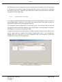
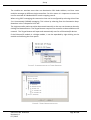
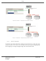
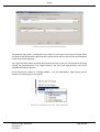
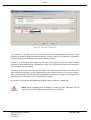
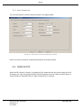
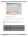
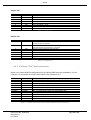
DF1 Router
Honeywell PLC Gateway (PLCG) setup
Technical Application Note
A-DF1R
Document No. D103-014
Document Revision 1.0
07/2015
CONTENTS
1.
Preface .......................................................................................................................................................... 2
1.1.
Purpose of this Document..................................................................................................................... 2
1.2.
Additional Information .......................................................................................................................... 2
1.3.
Support.................................................................................................................................................. 2
2.
Application Description ................................................................................................................................. 3
3.
Setup ............................................................................................................................................................. 4
4.
3.1.
Serial Cable wiring ................................................................................................................................. 4
3.2.
DF1 Router Setup .................................................................................................................................. 4
3.2.1.
Mapping ....................................................................................................................................... 4
3.2.2.
Serial Parameters ....................................................................................................................... 13
3.3.
Logix Setup .......................................................................................................................................... 13
3.4.
Honeywell PLCG Setup ........................................................................................................................ 14
3.4.1.
Jumper configuration ................................................................................................................. 14
3.4.2.
LCN Hiway “DHP” Box Configuration.......................................................................................... 15
Notes ........................................................................................................................................................... 16
4.1.
Example RSLogix and Slate code ......................................................................................................... 16
References ............................................................................................................................................................ 16
Preface
1.
PREFACE
1.1. PURPOSE OF THIS DOCUMENT
This document will assist the user to setup the Honeywell PLC Gateway module to
communicate with Logix/PLC-5/SLC via the DF1 Router.
1.2. ADDITIONAL INFORMATION
The following resources contain additional information that can assist the user with the
module installation and operation.
Resource
Slate Installation
DF1 Router User Manual
DF1 Router Datasheet
Example Code & UDTs
Ethernet wiring standard
CIP Routing
Map PLC/SLC messages
Link
http://www.aparian.com/software/slate
http://www.aparian.com/products/df1router
www.cisco.com/c/en/us/td/docs/video/cds/cde/cde205_220_420/installation/
guide/cde205_220_420_hig/Connectors.html
The CIP Networks Library, Volume 1, Appendix C:Data Management
SLC to CompactLogix Migration Guide: Chapter 3 – Map PLC/SLC Messages (1769ap001_-en-p.pdf)
EtherNet/IP Network Configuration: Chapter 5 – Mapping Tags (enet-um001_en-p.pdf)
1.3. SUPPORT
Technical support will be provided via the Web (in the form of user manuals, FAQ, datasheets
etc.) to assist with installation, operation, and diagnostics.
For additional support the user can use either of the following:
Contact Us web link
Support email
Document No. D103-014
Revision 1.0
07 / 2015
www.aparian.com/contact-us
[email protected]
Page 2 of 16
Application Description
2.
APPLICATION DESCRIPTION
The Aparian DF1 Router can be used to enable the Honeywell PLC Gateway (PLCG) to
exchange data with Logix, SLC, and PLC-5 controllers. The below diagram is an example of a
typical network setup.
FIGURE 1 - EXAMPLE OF A TYPICAL NETWORK SETUP
The Honeywell PLCG can also be setup for redundant communication as described in the
Honeywell PLCG setup.
FIGURE 2 - EXAMPLE OF A REDUNDANT NETWORK SETUP
Document No. D103-014
Revision 1.0
07 / 2015
Page 3 of 16
Setup
When setup correctly the Honeywell PLCG will request data by sending a DF1 message
request (over RS232) to the DF1 Router. The DF1 Router will then convert this message to the
required format and relay it to the configured Logix, SLC, or PLC-5 controller.
3.
SETUP
The following sections will describe the installation and configuration of all the required
devices to assist the user with the initial setup.
3.1. SERIAL CABLE WIRING
The serial cable pinout is shown in the figure below:
FIGURE 3 – SERIAL CABLE PINOUT
3.2. DF1 ROUTER SETUP
3.2.1. MAPPING
Document No. D103-014
Revision 1.0
07 / 2015
Page 4 of 16
Setup
The DF1 Router must be configured in either Transparent PCCC mode or Reactive Tag mode.
In Transparent PCCC mode the Logix PLC mapping will be used to route the PLC-2 emulated
messages to Logix Tags. In Reactive Tag mode the DF1 Router will map the PLC-2 emulated
messages directly to Logix Tags.
3.2.1.1.
TRANSPARENT PCCC MODE
In transparent mode the DF1 Router will redirect a DF1 PCCC message to a Logix controller at
a preconfigured path. Therefore, in this mode, the module will rely on the Logix controller to
map the DF1 request to the preconfigured Logix tag.
The transparent map configuration is a two-step process. First the DF1 Router must be
configured to route specific DF1 addresses to a controller path. The second step is to map the
DF1 addresses to Logix tags using RSLogix 5000.
To open the transparent map configuration window by double clicking on the module in the
tree or right-clicking the module and selecting Configuration. Once in the configuration
window select the third tab at the top Transparent PCCC. The transparent PCCC map
configuration is shown in the figure below.
FIGURE 4 - TRANSPARENT MAP CONFIGURATION
Document No. D103-014
Revision 1.0
07 / 2015
Page 5 of 16
Setup
The module can emulate more than one destination DF1 Node Address, and thus route
multiple messages to different Logix controllers. For this reason it is important to enter the
correct associate DF1 Node address in each mapping record.
When using PCCC messaging the connection class can be configured by selecting either Class
3 or Unconnected (UCMM) messaging. This is done by selecting from the Connection dropdown box in the Transparent PCCC tab.
The Logix controller paths can either be entered manually or the user can browse to them by
clicking the Browse button. The Target Browser requires the controller to be available on the
network. The Target Browser will open and automatically scan for all EtherNet/IP devices.
If the Ethernet/IP module is a bridge module, it can be expanded by right-clicking on the
module and selecting the Scan option.
FIGURE 5 - SCANNING NODE IN THE TARGET BROWSER
FIGURE 6 - TARGET BROWSER SELECTION
Document No. D103-014
Revision 1.0
07 / 2015
Page 6 of 16
Setup
The required Logix controller can then be chosen by selecting it and clicking the Ok button, or
by double-clicking on the controller module.
A maximum number of 20 controller mapping entries can be added.
The DF1 message initiator (e.g. DCS gateway) will send a read or write request to a specific
DF1 address on RS232. The user must configure the DF1 Router to route the message destined
for a specific DF1 address to a Logix controller. This will allow the correct Logix controller to
map the request to the Logix PLC/SLC mapped tag. For each route map the user must enter
two parameters as described in the table below.
Parameter
DF1 Node Address
Description
This parameter is one of the destination addresses that the DF1
Router will accept. Thus when the DF1 message initiator sends a
message to a specific DF1 node address that has been configured in
the module it will be accepted and routed to the paired Logix
Controller Path.
This is the destination node address of the message, and not the
source address of the DF1 device.
Logix Controller Path The CIP path to the end device (e.g. Logix controller). Refer to the
additional information section in this document for references to
details routed CIP path information. For example:
If the controller (slot 0) is in a chassis with a Ethernet bridge (IP
address 192.168.1.20) connected to the local network the user
would follow the format;
Ethernet bridge IP address, chassis backplane port, module slot etc.
192.168.1.20,1,0
TABLE 1 - TRANSPARENT MAP PARAMETERS
Below are two examples of how DF1 messages are routed to the Logix controller.
Document No. D103-014
Revision 1.0
07 / 2015
Page 7 of 16
Setup
FIGURE 6 – EXAMPLE 7 - TRANSPARENT ROUTING MAP – NODE 4
FIGURE 7 – EXAMPLE 8 – TRANSPARENT ROUTING MAP – NODE 7
3.2.1.2.
REACTIVE TAG MODE
The Reactive Tag routing mode allows mapping of virtual Data Files to Logix tags across
multiple controllers. This is similar to the Transparent PCCC mode except the mapping of data
files to Logix tags, is no longer managed in Logix, but in the DF1 Router itself.
Document No. D103-014
Revision 1.0
07 / 2015
Page 8 of 16
Setup
FIGURE 9 - REACTIVE TAG MODE CONFIGURATION
The Reactive Tag mode is configured in two steps. First the user must create a Target Name
(CIP path to the destination Logix controller) which will be used to link the DF1 Node Number
to the destination Logix tag.
The Logix controller paths can either be entered manually or the user can browse to them by
clicking the Browse button. The Target Browser will open and automatically scan for all
available EtherNet/IP devices.
If the Ethernet/IP module is a bridge module, it can be expanded by right-clicking on the
module and selecting the Scan option.
FIGURE 10 - SCANNING NODE IN THE TARGET BROWSER
Document No. D103-014
Revision 1.0
07 / 2015
Page 9 of 16
Setup
FIGURE 11 - TARGET BROWSER SELECTION
The required Logix controller can then be chosen by selecting it and clicking the Ok button, or
by double-clicking on the controller module.
A maximum number of 8 controller mapping entries can be added.
The second part of the Reactive Tag mode is to configure the link between a DF1 node to a
Logix tag.
NOTE: When using PLC-2 messages (used by Honeywell PLCG & EPLCG) there
are no data files. Thus the user must enter PLC2 in the space of the data file as
shown below. Only the DF1 Node address will be used to link the selected
Target Tag to the incoming PLC2 DF1 message.
Document No. D103-014
Revision 1.0
07 / 2015
Page 10 of 16
Setup
FIGURE 12 – REACTIVE TAG MAPPING
The module can emulate more than one destination DF1 Node Address, and thus route
multiple messages to different Logix controllers. For this reason it is important to enter the
correct associate DF1 Node address in each mapping record.
Below is an example of the target tag selection. The Target Tag can be either entered
manually or selected using the Tag Browser in Slate. The Tag Browser requires the controller
to be available on the network.
To browse to the tag, click on the Browse button. The Tag Browser will open and scan all the
tags inside that controller. If the controller has been recently scanned in this Slate session,
then a cached version of the tags will be displayed. A rescan of the tags can be triggered by
selecting the Refresh button in the Tag Browser’s toolbar.
All the non-array tags will be disabled, guiding the user to select a suitable tag.
NOTE: When mapping PLC2 messaging is used only INT datatypes will be
supported. Thus the Target Tag must be an array of INTs.
Document No. D103-014
Revision 1.0
07 / 2015
Page 11 of 16
Setup
FIGURE 13 – TAG BROWSER TAG SELECTION
The two figures below is an example of how DF1 messages are routed to the Logix tags using
the Reactive Tag Map mode.
NOTE: It is the user’s responsibility to ensure that the Logix tag array datatype
and size matches that of the PLC2 DF1 request. Failing to do this can result in
communication faults.
FIGURE 14 - REACTIVE TAG MODE CONFIGURATION IN SLATE
Document No. D103-014
Revision 1.0
07 / 2015
Page 12 of 16
Setup
3.2.2. SERIAL PARAMETERS
The serial parameters must be setup as shown in the figure below:
FIGURE 15 – DF1 SERIAL SETTINGS FOR HONEYWELL PLCG
Refer to the user manual for a detailed description of each parameter.
3.3. LOGIX SETUP
When the DF1 Router is setup in Transparent PCCC mode the user will need to map the PLC2
messages to a Logix Tag using the Map PLC/SLC Messages function. When the DF1 Router is
setup in Reactive Tag mode then no Logix configuration is required.
Document No. D103-014
Revision 1.0
07 / 2015
Page 13 of 16
Setup
FIGURE 16 – LOGIX PLC/SLC MAPPING
3.4. HONEYWELL PLCG SETUP
The Honeywell PLCG can be setup for either non-redundant or redundant communications.
3.4.1. JUMPER CONFIGURATION
NOTE: It should be noted that the TS1 pinning defines the board revision level to
the system and has no impact on the operation of the system.
Jumper TS1
Position
1
2
3
4
5
6
7
8
Jumper Setting
OUT
OUT
IN
IN
IN
OUT
IN
IN
Description
TABLE 2 – JUMPER TS1
Document No. D103-014
Revision 1.0
07 / 2015
Page 14 of 16
Setup
Jumper TS2
Position
1
2
3
4
5
6
7
8
Jumper Setting
IN
OUT
OUT
OUT
IN
OUT
OUT
OUT
Description
Port 2 Parity = Odd
Port 2 Baud Rate = 19.2K
Port 1 Parity = Odd
Port 1 Baud Rate = 19.2K
TABLE 3 – JUMPER TS2
Jumper TS3
Position
1
Jumper Setting
OUT
2
IN
3
4
5
6
7
8
OUT
OUT
IN
IN
IN
IN
Description
Non-Redundant EPLCGs. Change to IN when redundant PLCG
communication is required.
Non-Redundant Communications Enabled. Change to OUT when
redundant PLCG communication is required.
Reduced Communications Rate (optional)
Required
Required
Required
Required
TABLE 4 – JUMPER TS3
3.4.2. LCN HIWAY “DHP” BOX CONFIGURATION
Below is an example EB file configuration for the Hiway DHP Box (non-redundant). For this
example it is connected to Hiway 6, Box 8 with a PLC-5 address of 2.
Parameter
HWYNUM
BOXNUM
BOXTYPE
BOXASSN
LOADDEST
BOXSIZE
BOXPROT
PC1TYPE
PC1PORT
PC1PORTA
PC1ALIVE
PC1ALVBT
Selection
Description
HIWAY emulated by EPLCG
06
HIWAY BOX address being configured
08
HIWAY box type being configured
DHP
THISHG
HG_HIWAY
EXTENDED
Box communications protocol is Allen Bradley DF1
ALLENBRD
PLC Type
APLC
PLCG Port Nbr (Index)
1
Port – PLC Address.
2
“Keep Alive” not configured
0
0
TABLE 5 – EXAMPLE CONFIGURATION FOR HIWAY DHP BOX (NON-REDUNDANT)
Document No. D103-014
Revision 1.0
07 / 2015
Page 15 of 16
Notes
For redundant communication the following parameters must be configured in addition to
those in table 5.
Parameter
PC2TYPE
PC2PORT
PC2PORTA
PC2ALIVE
PC2ALVBT
Selection
Description
APLC
PLC Type
2
PLCG Port Nbr (Index)
2
Port – PLC Address.
0
“Keep Alive” not configured
0
TABLE 6 – EXAMPLE CONFIGURATION FOR HIWAY DHP BOX (REDUNDANT)
All other PLCxTYPE (where x is 3 – 8) parameters must be set to NOTCONFIG. In nonredundant mode PLC2TYPE will also be set to NOTCONFIG.
4.
NOTES
4.1. EXAMPLE RSLOGIX AND SLATE CODE
To assist the user an example RSLogix 5000 project as well as an example Slate project has
been placed on the Aparian website. These two projects have been configured as a pair
allowing the user to simply download both without additional work required.
REFERENCES
DeWitt, K. (2005). ControlLogix with a 1770-KFC15 to Honeywell EPLCG Serial Interface.
Document No. D103-014
Revision 1.0
07 / 2015
Page 16 of 16