1
SERVICE MANUAL
5Y18 CHASSIS
Design and specifications are subject to change without prior notice.
( ONLY REFERRENCE)
_____
ENGINEER BY:
_____
CHECKED BY:
PPROVED BY:
_____
36-43
44
Systems: a. North America: NTSC-M
b. South America and southeast Asia : NTSC-M/PAL
BG/DK/I/M/N
C.Europe: PAL SECAM
Power:
90-260VAC
Sound systems:a. AV STEREO(TONE CONTROL optional)
b. MTS STEREO(TONE CONTROL optional)
Sound power: STEREO
5W+5W OR 10W+10W (PIN TO PIN)
AV input/output:
1、
F.AV
2、
AV OUT
3、 AV IN optional:a. ONE FULL SCART
b. RCA&S-video
c. RCA&YUV
d. RCA&YUV&S-video
Other functions: TONE CONTROL/CCD/V-CHIP/LOGO/GAME/ calendar
/blue screen /lock/time
-3-
PDF 文件使用 "pdfFactory" 试用版本创建 www.fineprint.com.cn
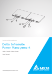
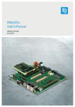
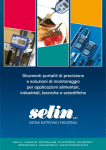
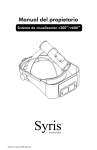
Chassis Block Diagram
-4-
Service Adjustments
1、
、 Please notice the following before Servicing
The main power is 90~260V/50/60Hz, Please be careful when you debug and
equip.
1-2、Don’t short any two soldering points, which should not be shorted and don’t
touch any components, which should not be touched.
1-3、Please disconnect the power plug from the wall outlet before servicing.
1-4、For safety reasons, all components equipped or replaced should be identical with
BOM.
1-5、Before alignment, ensure the TV set has been heated for at least 30 minutes and
degauss the CRT thoroughly with demagnetizer.
1-6、The data of EEPROM must be stored before the adjustment for main chassis.
1-1
2、 Tools and equipments for adjustment:
adjustment:
2-1、
2-2 、
2-3、
2-4、
2-5、
2-6、
2-7、
2-8 、
Item
small “-”screwdriver。
screwdriver without inductance
Pattern Generator。
Digital Voltmeter
DC Regulated power supply。
Sweep Signal Generator。
20MHz 2-channel Oscilloscope.
Signal condition(factory debug signal):
Logo
Picture
carrier
Pattern
System
Sound
mode
Remark
1
CHN-1CH
49.75
PHILIPHS
Picture
PAL—I
1KHz
2
WE-6CH
182.25MHz
Red filed
PAL—BG
L:
R:400HZ
3
CHN-12CH
695.25MHZ
Grey/
Half color bar
SECAM-D/K
BTSC
4
CHN-13CH
471.25
Cross hatch
PAL—D/K
1KHZ
5
USA-3CH
61.25
Color bar
NTSC—M
1KHZ
I NICAM
A2 STEREO
/TELETEXT
751.25
Monoscope
PAL—I
A:BTSC
B:MUSIC
C:1KHZ
294.25
Half color bar
PAL—BG
A:400HZ
B:1KHZ
STEREO
8
224.25
PHILIPHS
Picture
PAL—BG
A:BTSC
B:MUSIC
C:1KHZ
B/G
NICAM
9
85.25
Cross hatch
PAL—DK
BTSC
16:9
10
199.25
Cross hatch
NTSC—M
BTSC
MTS
573.25
Monoscope
NTSC—M
1KHZ
6
7
11
WE-S20CH
USA-31CH
-19-
Service Adjustments
3、 Adjust for main IC
3-1、
、Power check
Main voltage
Item
1
2
3
4
5
6
7
8
TESTING OF EACH VOLTAGE
Rating
Power
voltage
voltage
B+ Power supply
TFA Power supply (load)
UOC Main resistance
Memorizer power supply
Tuner power supply
Tune voltage
Vertical power supply
RGB power supply
130V±1V
20V±2V
16V±1V
5V±0.5V
5V±0.5V
33V±0.5V
26V±0.5V
190V±10V
70V
――
――
5V±0.5V
0V
――
0V
0V
Test
position
(positive pole of the
capacitor)
C532
C582
C542
W722
TUNER
C708
C452
C439
3-2、
、AGC adjustment
Method : Receive 60dB、751.25MHZ monoscope pattern, after pressing “PROD”
key three times TV SET will go to factory mode. Then pressing the “MUTE” key
three times to go to MENU3, select RF·AGE with “PROG+/-” key. Pressing
“VOL+-” key to change its value . Adjust W101 to 4V or just get the clearest picture.
At last press “PROD” key to exit the factory mode.
4、 COMPLETE MACHINE GENERAL ADJUSTMENT:
ADJUSTMENT:
4-1 、 Set TV to factory mode before aging line.
Method:Press “PROD” key to entering factory menu, Select the item by
“PROG+” and “PROG-”keys, Adjust it by “VOL+” and “VOL-“ keys, Press
“PROD” key to exit factory mode!
4-2 、 Focus Adjustment.
4-2-1、Receive monoscope pattern.
4-2-2、Set TV to work in dynamic status.
4-2-3、Adjust the focus knob of FBT to get the clearest picture.
4-3 、 Screen Voltage Adjustment :
4-3-1、Set TV at“TV”/“STANDARD”mode,no signal input;
4-3-2、Press key “PROD” two times to enter factory mode;
4-3-3、Press “MUTE “button on Remote Control ;
4-3-4、Adjust the screen knob of FBT to set the horizontal line just be seen, then press
“MUTE “button to return other factory menu .
-20-
Service Adjustments
4-4、
、 Horizontal Center and EW Adjustment
4-4-1、Receive 50HZ cross hatch pattern . Set TV standard status . Adjust H.PHASE
to obtain picture’s horizontal center at the center of CRT screen in factory MENU4 .
Receive cross hatch pattern . Set TV standard status ,.Adjust E/W DC、E/W TILE、
E/W AMP、E/W TOP、E/W BOTTOM to obtain picture’s horizontal redisplay ratio
more than 90% in factory MENU4.
E/W DC
50HZ Horizontal amplitude
E/W AMP
50HZ EW width
E/W TOP
50HZ EW upper corner parabola
E/W BOTTOM
50HZ EW lower corner parabola
E/W TILE
50HZ EW trapezium
H . PHASE
50HZ Horizontal center adjustment
4-4-2、Receive 60HZ cross hatch pattern. Set TV standard status, Adjust NT. H.
PHASE to obtain picture’s horizontal center at the center of CRT screen in
factory MENU1. Adjust NT .E/W DC 、NT .E/W AMP、NT .E/W TOP、
NT .E/W BOT to obtain picture’s horizontal redisplay ratio more than 90%
in factory MENU4.
NT .E/W DC
NT .E/W AMP
60HZ Horizontal amplitude
60HZ EW width
NT .E/W TOP
60HZ EW upper corner parabola
NT .E/W BOT
60HZ EW lower corner parabola
NT . H . PHASE
60HZ Horizontal center adjustment
4-5 、Vertical size and Linearity Adjustment
4-5-1、Receive 50HZ monoscope PATTERN. Set TV standard status. Adjust V.LINE、
V.SC and SHIFT to obtain vertical center at the center of CRT screen in factory
MENU0.
4-5-2、Receive 50HZ monoscope PATTERN. Set TV standard status. Adjust V.SIZE to
obtain picture’s vertical redisplay ratio more than 90% in factory MENU
-21-
Service Adjustments
V.LINE
V.SC
SHIFT
V.SIZE
50HZ Vertical linearity
50HZ Vertical S-correction
50HZ Vertical center
50HZ Vertical amplitude
4-5-3、Receive 60HZ monoscope PATTERN. Set TV standard status. Adjust
NT.V.LINE and NT.V.SC to change vertical size. Adjust NT.SHIFT to obtain
vertical center at the center of CRT screen in factory MENU0 .
4-5-4、Receive 60HZ monoscope PATTERN. Set TV standard status. Adjust
NT.V.SIZE to obtain picture’s vertical redisplay ratio more than 90% in
factory MENU
NT.V.LINE 60HZVertical linearity
NT.V.SC
60HZ Vertical S-correction
NT.SHIFT
60HZ Vertical center
NT.V.SIZE
60HZ Vertical amplitude
4-5-5、If necessary, adjust Horizontal Center and EW again.
4-6、
、 OSD position adjustment:
Receive 50/60HZ cross hatch pattern. Set TV standard status. Adjust OSD
H.POSI.and OSD V.POSI item to obtain menu OSD at the center of CRT screen in
factory MENU1;
4-7、
、 White Balance Adjustment
4-7-1、Set TV AV status and receive Black-White signal , connect the line to
XS703,then go to auto white balance adjustment;
4-7-2、Disconnect the line when the adjustment is OK;
4-7-3、White Balance Adjustment ( repairing)
4-7-4、Set TV AV status and receive Grey-White signal
4-7-5、The one sampling tube of CRT color analyzer (CA-100) covers on grey signal
and the another covers on white signal;
4-7-6、Go to factory mode,. Obtain Grey signal X=281 , Y=311 by adjusting R-BIA、
GBIA、B-BIA . Obtain White signal X=281 , Y=311 by adjusting R-DRV、
G-DRV、B-DRV. Obtain both X=281 and Y=311 by adjusting the two status
repeatedly .
4-7-7 Be this machine to take When the function of YUV and white balances
be partial to, need the white balance adjustment of carry on the
-22-
Service Adjustments
appearance of YUV.
Method:Enter the factory menu, adjust the YUV B- Y DC, the YUV R- Y
DC to adjust to try again and again, make the white
equilibrium the best.
4-8、
、CONVERGENCE ADJUSTMENT:
4-8-1、 Receive a dotted pattern. Set the TV receiver dynamic;
4-8-2 、Loose the convergence magnet clamper and make red with blue dots at the
center of the screen by rotating (R, B) static convergence magnets;
4-8-3、 Align Red/Blue with green dots at the center of the screen by rotating (RB-G)
static convergence magnet;
4-8-4、 Remove the DY wedges and slightly tilt the deflection yoke horizontally and
vertically to obtain the good edge convergence. Fix them after the good
overall convergence got.
4-8-5、 Fix the convergence magnets in turn of Left-Low, Right-Low Right-Up ,
Left-Up
4-8-6 、If purity error is found , adjust color purity.
4-9、SUB BRIGHT ADJUSTMENT:
Receive the gray scale . Get into the menu of factory mode. Then adjust the
SUB..BRI option to get a scale to be seen a little brightness(Only one-two rows can
be seen).
5、E2PROM
Adjustment( Department of engineering adjustment)
5-1、
、E2PROM Initializtion:
-23-
Service Adjustments
5-1-1、When in repairing, we can replace E2PROM by other empty or unempty
E2PROM,but you must initialize E2PROM to avoid unknown things.
5-1-2、When in manufacturing, first you read the data from a master E2PROM 24C08,
then write to other E2PR0M 24C08.
5-2、
、Function adjustment ( Department of engineering
adjustment)
Press remote control button PROD to entering factory adjust mode. Press MUTE
button to entering MENU3 , press MUTE button again after setting STEUP
SELECT to 1 , set up its function according as the order form.
FACTORY MENU DESCRIPTION (5Y18SEA)
MENU0
Item
Name
Instruction
0
V.SIZE
Vertical amplitude (0~127)
1
V.LINE
Vertical linearity (0~31)
2
V.SHIFT
Vertical shift(0~15)
3
V.SC
Vertical SC-correction (0~31)
4
NT.V.SIZE
Vertical amplitude offset of NTSC to PAL (-31~+32)
5
NT.V.LINE
Vertical linearity offset of NTSC to PAL (-7~+8)
6
NT.V.DC
Vertical out DC level offset of NTSC to PAL (-7~+8)
7
NT.V.SHIFT
Vertical shift offset of NTSC to PAL(-7~+8)
8
NT.V.SC
Vertical SC-correction offset of NTSC to PAL (-7~+8)
MENU1
Item
Name
Instruction
0
H.PHASE
Horizontal center (0~31)
1
NT.H.PHASE
Horizontal center offset of NTSC to PAL (-7~+8)
3
H.BLK.LEFT
Horizontal Left Blanking adjust (0~7)
4
H.BLK.RIGHT
Horizontal Right Blanking adjust
5
OSD H.POSI.
OSD horizontal position (0~63)
6
OSD V.POSI.
OSD vertical position (0~31)
7
SCR.H.POSI
SCR horizontal position (0~63)
8
OSD. CONT.
OSD contrast (0~7)
-24-
(0~7)
Service Adjustments
MENU2
Item
Name
Instruction
0
R-Y/B-Y G.BL
R-Y/B-Y Amplitude adjust (0~15),Default value 8
1
R-Y/B-Y ANG.
R-Y/B-Y Demodulation angle adjust(0~15),Default value8
2
B-Y DC LEVEL
White balance (0~15),Default value8;
3
R-Y DC LEVEL
White balance (0~15),Default value8;
4
PAL/M/N B-Y
PAL/M/N White balance (0~15),Default value8;
5
PAL/M/N R-Y
PAL/M/N White balance (0~15),Default value8;
6
YUV B-Y DC
YUV White balance (0~15),Default value8;
7
YUV R-Y DC
YUV White balance (0~15),Default value8;
8
G-Y AMP
G-Y Amplitude adjust(0~15)
9
G-Y ANGLE
G-Y Angle option0:240,1:253
MENU3
Item
Name
Instruction
0
SETUP SELECT
MENU4~22 switch option(0:lost/1:ok)
1
RF.AGC
RF.AGC adjust (0~63)
2
VOLUME
3
BTSC IC SEL.
BTSC IC selection (0:LA72700/1:TDA9850)
4
INPUT LEVEL
TDA9850 Amplitude of input signal (0~15) TDA9850 must be checked
5
SPECTRAL
TDA9850 Separate of high frequency (0~63) TDA9850 must be checked
6
WIDEBAND
TDA9850 Separate of low frequency (0~63) TDA9850 must be checked
7
ALC/LEVEL
ALC selection and SAP output amplitude(0:ALC OFF、LEVEL1/1:ALC ON、
LEVEL1/
2:ALC OFF、LEVEL2/3:ALC ON、LEVEL2) LA72700 must be checked
8
Item
H.SIZE COMP
MENU4
OUT Volume out adjust (0~127);Make sure stereo is turn on
Horizontal size compensate (0~7);
Name
Instruction
0
E/W DC
E/W DC level (0~63);
1
E/W AMP
E/W amplitude (0~63);
2
E/W TILT
E/W Tilt (0~63);
3
E/W TOP
E/W top corner correction (0~15);
4
E/W BOTTOM
E/W bottom corner correction (0~15);
5
NT.E/W DC
NTSC E/W DC level (-7~+8);
6
NT.E/W AMP
NTSC E/W amplitude (-7~+8);
7
NT.E/W TOP
NTSC E/W top corner correction (-7~+8);
8
NT.E/W BOT
NTSC E/W bottom corner correction (-7~+8);
9
E/W COR.SW
Control range of corner correction 0:STRONG SIDE,1:WEAK SIDE
-25-
Service Adjustments
MENU5
Item
Name
Instruction
0
ZOOM V.SIZE
Vertical size of magnified screen (0~127) Make sure ZOOM OPTION is 1
1
ZOOM DC
ZOOM E/W DC level (0~63);
2
ZOOM AMP
ZOOM E/W amplitude (0~63);
3
ZOOM TOP
ZOOM E/W top corner correction (0~15);
4
ZOOM BOTTOM ZOOM E/W bottom corner correction (0~15);
5
WIDE V.SIZE
Vertical size of wide screen(0~127);Make sure ZOOM OPTION is 1
6
WIDE DC
WIDE E/W DC level (0~63);
7
WIDE AMP
WIDE E/W amplitude (0~63);
8
WIDE TOP
WIDE E/W top corner correction (0~15);
9
WIDE BOTTOM WIDE E/W bottom corner correction (0~15);
MENU6
Item
Name
Instruction
0
STEREO OPT.
Volume control option(0:decode inside control/1:single PWM/2:double
PWM/3:LV1116 control)
1
LV1116 GAIN
LV1116 Gain control(0~7)
2
SUR. MODE
Surround mode option(0~7)(6is the same as 7)
3
WOOFER GAIN
Woofer gain control(0~7)
4
LV1116 PORT
LA1116 Input port option(0:2input/1:3input)
5
MUTE LEVEL
PMUTE Mute output level option(0:high level /1:low level)
6
VOLUME OPT.
Option of volume linearity control(0:fool control mode /1:four parts
equality and linearity control mode)
7
VOLUME 25
8
VOLUME 50
Four parts equality and linearity control mode,Volume 25,LA7650 output
(0~63)
Four parts equality and linearity control mode,Volume 50,LA7650 output
(0~63)
9
VOLUME 75
Four parts equality and linearity control mode,Volume 75,LA7650 output
(0~63)
MENU7
Item
Name
Instruction
0
S.TRAP TEST
Narrow-band sound trap wave frequency adjust (0~7);Default : 4。
1
S.TRAP.SW
Inside/outside trap wave selection (0:inside 1:outside),Default : 1
2
VOL. FILTER
Volume control and filter function(0:no 1:yes );commonly select 0。
3
A.MONI.SW
4
4.5M OPTION
Pin 2 output Selection ( 0 : TV audio-output 1 : TV audio-output ; AV
audio-output)
4.5M Sound system option(1:yes / 0:no )
-26-
Service Adjustments
5
5.5M OPTION
5.5M Sound system option (1:yes / 0:no )
6
6.0M OPTION
6.0M Sound system option(1:yes / 0:no)
7
6.5M OPTION
6.5M Sound system option(1:yes / 0:no)
8
THAI DUAL
Thai dual option(1:yes / 0:no)
9
TFA9843A OPT
TFA9843A option(1:yes/ 0:no)
MENU8
Item
Name
Instruction
0
AUTO OPTION
Color system AUTO option(1:yes / 0:no )
1
AUTO1/2 OPT.
Color auto identify option (0:auto identify PAL/NTSC3.58/NTSC4.43 / 1:
auto identify PAL-M/PAL-N/NTSC3.58)
2
PAL OPTION
PAL Color system option(1:yes/ 0:no )
3
PAL-M OPTION
PAL-M Color system option(1:yes / 0:no)
4
PAL-N OPTION
PAL-N Color system option(1:yes/ 0:no)
5
N3.58 OPTION
NTSC3.58Color system option(1:yes / 0:no)
6
N4.43 OPTION
NTSC4.43Color system option(1:yes/ 0:no)
MENU9
Item
Name
Instruction
0
C.TRAP TEST
Color trap wave control (0~7)
1
C.BPF TEST
Color BPF control (0~3)
2
C.KILLER OPE
Color killer start setting (0~7)
3
PAL APC SW
PAL APC switch (0~1);default value 0。
4
APC OFFSET
APC OFFSET current(0~7)
5
C.VCO.ADJ.
NTSC/PAL-M/PAL-N Adjust VCO frequency(0~7)
6
C.BYPASS
Bypass color band-pass filter(0:no/1:yes)instruction: 1: throw;
0:hold。
MENU10
Item
Name
Instruction
0
SEARCH TYPE
South America tune mode(1:yes /0:no)
1
TUNER OPTION
Tuner mode option (0:voltage/1: frequency)
2
VL/VH FREQ.
Tuner VL/VH frequency selection :(VL highest frequency +VH lowest
frequency)/2-100.25MHz
3
VH/UHF FREQ.
Tuner VL/UHF frequency selection:( VL highest frequency +UHF lowest
4
BAND OPTION
Tuner UHF carry mode selection (0:00000100B / 1:00001000B)
5
CATV BAND
South America tune mode CABLE(0:STD / 1:STD、IRC and HRC)
6
SEARCH SPEED
Search speed option(0:low mode/1:fast mode)
7
SEARCH CHECK
Auto search check when cold power on (1:yes/0:no)
-27-
Service Adjustments
MENU11
Item
Name
Instruction
0
AV OPTION
AV input option(0~3)
1
S-VIDEO OPT.
S-Video input function option(0:no 1:yes)
2
YUV OPTION
YCbCr input function option(1:yes /0:no)
3
DVD OPTION
DVD option(1:yes /0:no)
DVD CHANNEL
DVD channel option(0~3)please notice the following
(1)AV OPTION=1 and DVD OPTION=1
0: DVD(VIDEO)S-VIDEOYUV
1: no
2: VIDEODVD(S-VIDEO)YUV
3: VIDEOS-VIDEODVD(YUV)
(2)AV OPTION=2 and DVD OPTION=1
0: DVD(VIDEO)VIDEOS-VIDEOYUV
1: VIDEODVD(VIDEO)S-VIDEOYUV
2: VIDEO1VIDEO2DVD(S-VIDEO)YUV
3: VIDEO1VIDEO2S-VIDEODVD(YUV)
(3)AV OPTION=3 and DVD OPTION=1
0: DVD(VIDEO) VIDEO1VIDEO2S-VIDEOYUV
1: VIDEO1VIDEO2DVD(VIDEO)S-VIDEOYUV
2: VIDEO1VIDEO2VIDEO3DVD(S-VIDEO)YUV
3: VIDEO1VIDEO2VIDEO3S-VIDEODVD(YUV)
MENU12
Item
Name
Instruction
0
POWER OPTION
Power original state option(0:off /
1
POWER LOGO
Power logo option (1/0);make sure its value is “1” after factory setting
2
SCREEN OPT.
Screen option of power on/off (0:no / 1:on / 2:off / 3:both)
3
SCREEN TYPE
Screen type option (0:normal/1:fade in fade out)
4
SCREEN TIME
Screen waiting time selection (0~7seconds)
5
V.MUTE P.OFF
Disconnect audio output to CRT before POWER OFF(1:yes/0:no)
6
DISCHARGE
DC power off discharge control(0:no/1:yes)
7
UHF/DEGAUSS
LA76933 pin 39th function option(0:UHF control/1:DEGAUSS control)
-28-
1.:remember / 2、3:on)
Service Adjustments
MENU13
Item
Name
Instruction
0
LINE MODE
B/W BALANCE,Picture mode of line and full screen changing(1:yes/0:
no)
1
GRAY MODE
Inside test signal output level setting (0:white 70%/ 1:ash 15%)
,Default0
2
EVERY DAY
Time menu availability option(1:every time /0:one time)
3
HOTEL MODE
Hotel mode (1:yes/0: no)
4
HOTEL VOLUME
Hotel mode largest volume control (0~100)
5
ON POSITION
Hotel mode program option(0~255)
6
ON TV/AV
Hotel mode TV/AV option(0:TV/1:AV)
7
ZOOM OPTION
Zoom option(1:yes /0:no)
8
CHILD LOCK
Child lock function option (1:yes /0:no)
MENU14
Item
Name
Instruction
0
GAME-MONEY
Game-money function option(1:yes/ no)
1
GAME-CRAB
Game-crab function option(1:yes/ 0:no)
2
GAME-TETRIS
Game-tetris function option(1:yes/ 0:no)
3
GAME-888
Game-888 function option (1:yes/ 0:no)
4
LOTTERY
Game-lottery function option(1:yes/ 0:no)
5
CALENDAR
Calendar function option (1:yes/ 0:no)
6
BIO-CLOCK
Bio-clock function option(1:yes/ no)
7
PHONE BOOK
Phone book function option(1:yes/ 0:no)
MENU15
Item
Name
Instruction
0
ENGLISH OSD
English OSD (1:yes /no)
1
CHINESE OSD
Chinese OSD (1:yes /0:no)
2
INDONESIA
Indonesia OSD(1:yes /0:no)
3
SPANISH OSD
Spanish OSD(1:yes /0:no)
4
PORTUGAL OSD
Portugal OSD (1:yes /0:no)
5
ITALIAN OSD
Italian OSD(1:yes /0:no)
6
VIETNAMESE OSD
Vietnamese OSD (1:yes /0:no)
7
FRANCE OSD
France OSD(1:yes /0:no)
8
THAI OSD
Thai OSD (1:yes /0:no)
-29-
Service Adjustments
MENU16
Item
Name
Instruction
0
BLK PROCESS
Black option in process of channel changing(1:yes /0:no)
1
BACK COLOR
Back color option in mute condition(0:blue / 1:black)
2
POSITION L/R
OSD position L/R (0:left / 1:right)
3
SCREEN SAVER
4
SAVER TOP
Screen saver option(0:LOGO only;1:the 1th row character;2:the 2th
row character;3:both rows )
Screen saver top (0~255)
5
SAVER BOTTOM
Screen saver bottom(0~255)
6
SAVER LEFT
Screen saver left (0~255)
7
SAVER RIGHT
Screen saver right(0~255)
MENU17
Item
Name
Instruction
0
HALF TONE
Half tone adjust(0~3)
1
MENU BACK
Menu background (1:yes /0:no)
2
M.BACK COLOR
Menu back color (BLK:back/BLU:blue/GRN:green/CYN:cyan/RED:red/MAG:
purple/YEL:yellow/ WHI:white)
3
MENU H.TONE
Menu half tone option(0:no/1:half)
3
MENU ICON
Menu icon option(0:yes/1:no)
5
ICON BACK
Menu icon back (1:yes /0:no )
6
ICON H.TONE
Menu icon half tone option (0:no /1:half)
7
PROMPT TYPE
Menu prompt type option(0:single / 1:double)
MENU18
Item
Name
Instruction
0
V.COMP
Vertical compensate adjust(0~3)
1
V.SEPUP
Vertical synchronization separate sensitive enhance setting (0:normal mode/ 1:father
mode ),Default : 1
2
SYNC.SEP.SEN
Vertical synchronization separate sensitive gate level setting (0~7) ,Default : 3
3
V RESET TIMING
Vertical reset timing(0:normal 1:0.25H phase shift)
,Default : 0
4
C.D.MODE
Vertical count mode(0~7),Default0
5
V.TRANS
Vertical athwart data transfer,0:normal,1:data transfer mode;
6
V BLK SW
Vertical blanking switch (0:normal mode 1:wide mode)
,Default : 0
7
FBPBLK. SW
Horizontal blanking switch(0:come from inside logic 1:come from inside
logic/FBP)
,Default : 1
-30-
Service Adjustments
MENU19
Item
Name
Instruction
0
SUB. CONT.
Sub-contrast (0~31)
1
SUB. COLOR
Sub-color adjust (0~15)
2
SUB. SHARP
Sub-shape adjust (0~31)
3
SUB. TINT
Sub-tint adjust (0~63)
4
BRT.ABL.DEF
Auto-bright
5
MID.STP.DEF
Auto-bright center control (0:on / 1:off)
6
BRT.ABL.TH
Auto-bright gate control (0~7)
7
OVER.MOD.SW
Over modulate function switch (0:off 1:on)
8
OV.MOD.LEVEL
Over modulate level(0~15)
control (0:on / 1:off)
MENU20
Item
Name
Instruction
0
CORING W/DEF
Coring noise control(0:off 1:least Plus 3:most plus)
1
PRE SHOOT
Bright signal pre-edge shoot adjust (0~3)
2
OVER SHOOT
Bright signal back edge shoot adjust (0~3)
3
Y GAMMA STA.
Y GAMMA correction start setting(0:None 1:High 3:Low)
4
DC.REST
DC reset option (0:100% 1:107% 2:113% 3:129%)
5
WPL OPE.
WPL Operation point option(0~3)0:Default ,1:High,3:Low
6
SH ADJUST
Shape attribute adjust(0,normal;1,self-adapt)
7
BLK.STR.OPT.
Black level stretch screen display option(1:yes /0:no)
8
BLK.STR.STA.
Black level stretch start setting(0:high 2:low 3:none)
9
BLK.STR.GAIN
Black level stretch plus adjust(0~3)
MENU21
Item
Name
Instruction
0
AFC GAIN
AFC gain (0:AUTO / 1:HIGH) ,Default : 0
1
VIF.SYS.SW
Picture mid-frequency setting(0:38.0M 1:38.9M 2:39.5M 3:45.75M)
2
VIDEO.LEVEL
Video demodulation output level(0~7)
;Default : 4。
3
V.LEV.OFFSET
Video demodulation output offset level (0~3)
4
RGB TEMP SW.
RGB output temperature compensate switch(0:off 1:on)
5
VCO FREQ.
Picture mid-frequency VCO frequency adjust(0~255)
6
VCO ADJUST
VCO Correction(0~15)
7
SVO OR FSC
Pin 52 output signal(0:Video output 1:Color Sub-carrier wave output)
Default : 0
8
BLANK DEF
RGB Output H/V BLK {0:on(normal mode) 1:off }
-31-
Service Adjustments
MENU22
Item
Name
Instruction
0
Y TH
Signal’s delicacy of Blue level extend(0~3)Default : 0
1
Y GAIN
Blue level stretch gain adjust(0~3)Default : 0
2
R WIDTH
Blue level stretch gain adjust(0~3)Default : 0
3
R OFFSET
Blue level stretch gain adjust(0~3)Default : 0
4
B WIDTH
Blue level stretch gain adjust(0~3)Default : 0
5
B OFFSET
Blue level stretch gain adjust(0~3)Default : 0
6
VM/AUDIO SW
VM Output/AUDIO outside output switch ,0:AUDIO outside output,1:VM output
7
VM DELAY ADJ VM Delay time(0~3)
8
VM GAIN
VM Gain option(0~7),0:Default
Form2:Factory setting
Item
SHIP1
SHIP2
Channel
1
1
Volume
0
0
Picture mode
PERSONAL
PERSONAL
Sound mode
MUSIC
MUSIC
Tint
0
0
Balance
0
0
Color system
AUTO
AUTO
Sound system
I
BG
Language
ENGLISH
ENGLISH
-32-
34
36
1
2
3
4
5
6
7
8
XS803 S-VIDEO
Y
Cr
Cb
C
Y
C844
10/50V
L OUT
C804
0.01
V802
2SC1815
R803
1K
R856
82R
R809
560
+
+
R851
82R
R207
1k
C852
50V1
R850
82R
C853
50V1
C855
0.01
R855
82R
R852
82R
R853
82R
R705
2.7K
R704
3.9K
XS701
SCN-5
L OUT
7
8
VSS
VD411 R722
HZ7C3 1M
C208 16V0.47
R413
10K
C207
0.1
C701
100/16V
+
3
3
2
2
1
1
R920
1K R921
2K7
+
VD904
1N4148
VD402
1N4148
R922
680
R243
B6
12V
270/1/4W
R774
560
5V
R773
560
PUM P O UT
2
3
GN D
OU TPUT
4
5
VCC1
NO N IN PU T
6
SCL
SDA
+
B5
VD452
1Z75 R460
180/1/2W
R456 R457
12K
39K
C452
1000/35V
R453
12K
R403
330K
B2
+
26V
SDA
SC L
GN D
VC C
R435 VD441
270/2W EU2A
C444
160V1
C434
47/35V
V432
2SC5299
B6
12V
R501
1/2W-2M2
FSCQ1265RT
3
VCC
1
4
3
2
1
RF542
0.47R/1W
4.7V
C519
47n/63V
C520
100n/63V
4
C572
470/16V
+
B4
SOUND
22V
R655
1K
R665
1K
VD601
1N4148
R572
56R/3W
+
C669
10/16V
B7
+
VDZ541
R544 3V3
1K5/1/2W
R542
4K7/1/4W
N502
R543
47K/1/4W
N503
KA431
VD543
PDF created with pdfFactory trial version www.pdffactory.com
C667
47/16V
R651
3K9
R601
10K
C668
12n
R661
3K9
L-IN
C665
47/16V
C663
470/25V
+
B6
12V
C543
100n
22V
VD602
1N4148
+
C601
100/16V
C604
10n
V603
2SC1815
USOC CHASSIS COLOR TV
C773
4.7/16V
FOCUS
6
SCREEN
C603
+ 1000/35V
5
C433
500V 3900P
8
R471
7W3R9
B1
130V
R233
1/2W 1K5
+
C470
10/160V
R316
560
R329
220
R323
330
C432
500V 1000P
R319
2K7
V302
2SA1015
V305
2SA1015
C305
3.3/100V
R320
1K5
D
R313
3R3/1W
R322
62K
R324
3K9
V304
2SC1815
R328
560
C231
50V 1U
L301
2854
R330
1K
R314
560
R317
560
R325
3K3
VD301
1N4148
R318
1K
V301
3DD3853
V303
2SA1015
R327
10K
Title
R326
12K
TJC3-2Y
XS601 TJC3-2Y
B901
5W 8HM
7
3
C439
22/220V
E/W
XS602
MAIN BOARD
4
VO L-R
VO L-L
VO L1
470/25V
C652
0.1
R653
2R2 1/4W
C662
0.1
R663
2R2 1/4W
B4
R604
10K
R602
10K
R533
1K5/1/4W
V602
2SC1815
R603
10K
V601
2SA1015
R540
1K
3
10
R433
1/2W 1K
B6
12V
+
Size
B902
5W 8HM
Number
Revisio n
A2
Date:
File:
6
XS401
SCN-4Y
HV
R232
10K
R777
100K
+ C653
1
4
+
C774 R778
4.7/16V 100K
C
2
B3
180V
9
13
OU T1
12
11
NF1
PWR G ND
10
OU T2
NF2
9
8
VCC
VO L2
STB
R662
10K
3
T471
BSC23-N0120
VD561 R550
EU2A 1R/1/2WF
VD441
R492
EU2A 1R/1/2WF
+
R943
1/2W 220K
V431
2SC2383-O
C658
12n
C602
10/16V
+
R-IN
C530 2200P/AC400
2
C651
10/16V
R652
10K
V540
2SC1815
LIVE AREA
D?
+
1N4148
VD542
1N4148
+
B3
180V
C661
+ 10/16V +
+
C659
10/16V
RP551
B-20K
IN 2
+
C654
100/16V
5V
R541
4K7/1/4W
HS817
V661
2SC1815
7
3
6
2
V651
2SC1815
5
1
C666
10/16V
4
B1
130V
C656
10/16V
7805
PRE GN D
N552
IN 1
1N4148
C582
2200/25V
BCK-160-L001A7A
VDZ502
FB
N601
LA42352
R654
15K
R664
15K
4
2
C562
470/35V
+
8
18V/1W
+
R573
27R/2W
VD544
B6
12V
C574
470/16V
+
R530
8M2/1/2W
AC90~260V
50/60Hz
VD581
RU4AM
C581
15 470P/2KV
VD508 1N4148
C517
50V10
1K
R532
68K/1/2W
VDZ501
5
SYNC
FU501
R509
T3.15A H250V 510R/1/2W
XS502
NISPT-2
R531
47K/2W
+
C532
220/160V
10 C531 470P/2KV
16
2
C501
250HM0.22
7
R547
B2
26V
B6
12V
10R/1/2W
C516
50V10
R508
VD507
1K5/1/2W FR105
C515
100V 2n2
GND
L501
LCL-07G/18mH
R506
R546
10K
R491
2R2/1W
1
3
L OUT
150K/1W
N501
1
D
+
VD531
RU4AM
V541
BD034
2
3
R507
1K/1/2W
R504
11
+
C542
2200/35V
C541 470P/2KV
1
R OUT
C502
VD506
FR105
9
N553
7812
C545
10n
+
2
4
C514
2KV 1000P
VD541 RF541
EU2A 0.47R/1W
13
3
C567
220/16V
R545
2R2/2W
FILTER
L503
100K/1W
L502
LCL-07G/18mH
250HM0.22
D
2
3
VD505
FR105
L504
Z2073
VD501
VD504
RM11C
R502 10W-3R9
C504
400V 1000P
C512
630V 22n
2
1
C505
100n/250V
00
RT501
PTDCA1BF7R0Q100
C510
+ 400V220
12
+
1
TJC2-2 A
C503
400V 1000P
1
T501
R505
3W 56K
XP402
TJC2-5Y
B2
12V
C450
100/16V
R441
1K/1W
C437
33n/630V
7805
C509
1KV4700P
R503
5V
+
C506
R458
1K
R446
10K/1W
VD446
EU2A
L431
T431
JDT1904 0.22/2W
N702
CPUB5
1
C457
25V2200
L441
TLN2083
+
C441
390n/400V
C440
43n/400V
R434
270/2W
2
+
+
L433
TLN501K
C713
100
3
R459
1WJ 0R82
R745
100
C712
100
XS402
TJC2-5A
C458
100V 33n
C456
2.2/50V
R454
3K
C720
10n
R744
100
C723
47/16V
+
R455
12K
AT24C08
AHA-HXC-38A1
C906
10/16V
4
+
L451
18uH
C453
1000
R775
4K7
R776
4K7
R734
4K7
B7
5V
JQX-141FF-012-HSP-HS
+
C459
R452
1R 0.1/100V
C455
10P/500V
+
32
B2
26V
C
N541
R924
4K7
VD451
EM01Z
V- OUT
C407
50V 1U
R771
3K3
R772
3K3
C408
100n
XS504
SCN-4Y
V908
2SA
R451
5K6
R749 4K7
R736
4K7
R735
10K
C115
16V100
C706
220
VD905
1N4148
C451 100/35V
SC L
SDA
POWE R
31
30
TU
VO L-R
29
28
VO L-L
26
25
IR
AV /TV
AV 1 /AV 2
M UTE
24
23
R409
150
R402
3K3
C406
33n
R404
1K
2
1
+
C454
50V1
R400
2201/4W
VD401
1N4148
VD909
1N4148
+
7
VI DEO /V/ BUS G ND
H O UT
22
21
20
C405
0.01
B7
SIGNAL
5V
C116
0.01
H A FC FIL
H/ BUS V CC
VCO I REF
19
18
17
V O UT
V RAM P FIL
R273
4K75 1%
C403
0.47
C245 C244
0.01 16V220
C129
0.01
R904
820
+
XT1
XT2
VD D
KE Y IN
(SCL) VL
(SDA )VH
(U )DEGA USS
RESET
PLL
C PU GN D
C CD VCC
FBP IN
YC- C IN
YC- Y IN
NC
YU V-Y IN
Cr IN
4.4 3M CRYSTAL
15
14
EW
B OUT
G O UT
13
12
R OUT
RGB VC C
11
10
ABL
EX T. A UD IO IN /VM O UT
9
8
7
R123
3K3
C707
180
C404
100U
VD246 VD245 VD244
8V2
8V2
8V2
R710
33K
R711
27K
N451
LA78041
+
C123
1000
R119
1K
R103
18K
IF VCC
SIF A PC FIL
AU DIO OUT
SEL A UDI O OU T
6
FM FIL
5
4
SIF I N
PIF A GC
C125
39P R120
L121 10K
15uH
C210
22n
3
C908
C907
0.47u/16V 220/16V
V907
2SC2120
R923
56
G
+
C124
0.01
R121
10K
N705
UPC574
C708
50V4.7
V701
2SC1815
C709
FK0.47
B1
130V
C117
50V1 +
R914
15
4
33
34
35
36
37
38
39
40
41
42
43
44
45
46
47
48
49
50
51
R903
56
C436 8K2/2000V
ET-5H5E-AF101AH
+
B
5
R714
5K6
C710
FK0.47
R104
68K
C104
16V 2.2
C278
+ 16V100
4
C702
0.01
4
V902
2SC
C901
470P
XP902
SCN-5Y L901
10uH
5
5
G701
32.768K
R709
470K
C729
50V/0.33
6
+
R724
150K
8
R715
5K6
BT
AGC
+
7
+
R712
10K
C711
FK0.47
C126
18P
R718
15K/2W
C102
0.01
R716
5K6
3
SIF O UT
R111
27
BL(SDA)
+
2
C120
22n
B7
5V
R717
1K
XS403
SCN-5
R747 4K7
R109
1K
1
C112
0.01
V102
2SC2216
BM 2
C106
50V1
B6
12V
L121
15uH
R110
220
C101
16V47
12V
N101
LA76933
+
R108
5K6
+
B6
C705
18P
K6D
B
16
C617
10/50V
+
R107
100
BT2
C704
18P
50V2U2
C277
0.01
XP901
R
Cb IN
SEL V IDEO OU T
C APC FIL
EX T VID EO IN /Y IN
VI DEO /V V CC
IN T VID EO IN /S-C IN
B LK D ET. FIL
APC FIL
AFT FIL
VIDEO O UT
RF A GC OU T
IF GND
PIF I N2
PIF I N1
AV/TV
FO
R902
470
R618
100
R617
100
C110
0.01
R925
15K/2W
R901
560
R
G201
S4.43
52
55
56
57
58
59
60
61
62
63
64
+
53
C206
AV/TV
R OUT
+
AV1/AV2
HJ1967
100/16V
C205
0.01
R204
560K
+
R842
27K
C909
2KV1000
R908
820
VD907
1N4148
5V
C722
54
9
10
11
12
13
14
15
16
C206 0. 47/50V
C
B
A
0X
1X
X COM
Y COM
VD D
C
9
10
11
B
A
0X
12
1X
13
14
VEE
6
5
0Z
IN H
4
3
Z COM
1
2
1Z
0Y
1Y
VSS
VEE
IN H
0Z
Z COM
1Z
X COM
0Y
1Y
Y COM
VD D
15
16
TV LIN
AV-L IN
+
7
6
5
4
3
2
1
8
C204
16V1
C203
16V2. 2
Z101
C618
10/50V
TV RIN
R951
15
V904
2SC
R906
470
IR
R721
100
A
VD908
1N4148
R905
560
C905
10/16V
TV LIN
+ C105
16V4.7
12V
C721
33n
R271
100
R205
24K
+
C119
0.01
C211
50V/1
+
C118
0.1
+
R202
560
R412
10K
R206
24K
R122
560
R114 47K
C801 C800
16V220 0.01
R841
10K
BH(SCL)
BU(AS)
5V
XS901
GZS10-2-102G
R917
15K/2W
V903
2SC2688
V901
2SC2688
R113
47K
B7
5V
+
B6
R926
2K7/1/2W
R912
820
C903
390P
VD701
TRL-R
B5
R911
56
C902
390P
+
AV-R IN
C103
16V4. 7
4
B7
5V
+
C802
0.01
BM 1
3
R910
470
C728
4.7/16V
R907
56
R201
560
B7
5V
IF
2
R916
2K7/1/2W
V906
2SC
B5
B7
5V
A101
1
R909
560
B
R727
470
+
TC4053BP/BF
C111
0.01
R766
100
R700
150K
KEY
TC4053BP/BF
V841
2SC1815
R701
27K
AV/TV
N802
R918
2K7/1/2W
V905
2SC2688
G
N801
C814
10/50V
R702
8.2K
R708
10K
AV-L IN
TV RIN
B
R703
4.7K
+
R707
680
L OUT
AV-R IN
CRT BOARD
A701
HS0038A
VD909
1N4148
R706
1.5K
A
C813
10/50V
SW701
CH+
SW702
CH-
R854
82R
27
+
+
R801
1K
C803
0.01
SW703
VOL+
VCC2
C810
50V10
R805
82R
R806
82R
V202
2SC1815
SW704
VOL-
SW705
MENU
R461
120/1/2W
+
82
+
C809
50V10
R818
R808
82R
R827
82R
SW706
AV/TV
IN PU T
R802
15K
C842
10/50V
V801
2SC1815
C845
10/50V
+
C816
50V10
R OUT
C843
10/50V
+
C815
50V10
R821
82
R816
100
R815
100K
SW707
POWER
+
C811
50V1
R814
100
R813
100K
+
R812
100
R811
100K
+
C817
50V1
R810
100
R800
100K
R804
15K
B6
12V
+
R807
82
B7
5V
R817
82
XS801
R915
15K/2W
V OUT
R OUT
L OUT
XS804
1
AV-OUT
L2 IN
R2 IN
V2 IN
XS804-3
C4358K2/2000V
VD436 RU4C VD435 RU4DS
AV2
L1 IN
R1 IN
V1 IN
XS803
+
AV1
7
20 06-7- 7
F:\SW9 33.SCHDOC
Sh eet of
Drawn By:
8