1
&KDQJHIRU/LIH
6HUYLFH0DQXDO
02'(/ *:+0%.'1$.
*:+0%.'1$.
*:+0%.'1$.
*:+0%.'1$.
*:+0%.'1&.
*:+0%.'1&.
*:+0%.'1(.
*:+0%.'1(.
5HIULJHUDQW5$
*5(((/(&75,&$33/,$1&(6,1&2)=+8+$,
7DEOHRI&RQWHQWV
7DEOHRI&RQWHQWV
6XPPDU\DQG)HDWXUHV 6DIHW\3UHFDXWLRQV 6SHFL¿FDWLRQV 8QLW6SHFL¿FDWLRQV 2SHUDWLRQ&KDUDFWHULVWLF&XUYH &DSDFLW\9DULDWLRQ5DWLR$FFRUGLQJWR7HPSHUDWXUH 1RLVH&ULWHULD&XUYH7DEOHVIRU%RWK0RGHOV 2SHUDWLRQ'DWD &RQVWUXFWLRQ9LHZV ,QGRRU8QLW 2XWGRRU8QLW 5HIULJHUDQW6\VWHP'LDJUDP 6FKHPDWLF'LDJUDP
(OHFWULFDO'DWD
(OHFWULFDO:LULQJ
3ULQWHG&LUFXLW%RDUG )XQFWLRQDQG&RQWURO 5HPRWH&RQWURO2SHUDWLRQV 'HVFULSWLRQRI(DFK&RQWURO2SHUDWLRQ ,QVWDOODWLRQ0DQXDO 1RWLFHVIRU,QVWDOODWLRQ ,QVWDOODWLRQ'UDZLQJ ,QVWDOO,QGRRU8QLW ,QVWDOO2XWGRRU8QLW &KHFNDIWHU,QVWDOODWLRQDQG2SHUDWLRQ7HVW ,QVWDOODWLRQDQG0DLQWHQDQFHRI+HDOWK\)LOWHU 7DEOHRI&RQWHQWV
([SORGHG9LHZVDQG3DUWV/LVW ,QGRRU8QLW 2XWGRRU8QLW 7URXEOHVKRRWLQJ 0DOIXQFWLRQ$QDO\VLV )ODVKLQJ/('RI,QGRRU2XWGRRU8QLWDQG3ULPDU\-XGJHPHQW +RZWR&KHFN6LPSO\WKH0DLQ3DUW 5HPRYDO3URFHGXUH 5HPRYDO3URFHGXUHRI,QGRRU8QLW 5HPRYDO3URFHGXUHRI2XWGRRU8QLW 6XPPDU\DQG)HDWXUHV
6XPPDU\DQG)HDWXUHV
,QGRRU8QLW
*:+0%.'1$.,
*:+0%.'1$.,
*:+0%.'1$.,
*:+0%.'1$.,
*:+0%.'1&.,
*:+0%.'1&.,
*:+0%.'1(.,
*:+0%.'1(.,
2XWGRRU8QLW
*:+0%.'1$.2
*:+0%.'1$.2
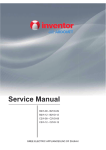
5HPRWH&RQWUROOHU
<%)$
MODE
ON /OFF
FA N
C LOCK
TIMER ON
X-F AN
T EMP
TIMER OF F
T URBO
SLEEP
LIGH T
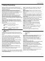
6DIHW\3UHFDXWLRQV
6DIHW\3UHFDXWLRQV
,QVWDOOLQJVWDUWLQJXSDQGVHUYLFLQJDLUFRQGLWLRQHUFDQEH
KD]DUGRXVGXHWRV\VWHPSUHVVXUHHOHFWULFDOFRPSRQHQWVDQG
HTXLSPHQWORFDWLRQHWF
2QO\WUDLQHGTXDOL¿HGLQVWDOOHUVDQGVHUYLFHSHUVRQQHODUH
DOORZHGWRLQVWDOOVWDUWXSDQGVHUYLFHWKLVHTXLSPHQW
8QWUDLQHGSHUVRQQHOFDQSHUIRUPEDVLFPDLQWHQDQFHIXQFWLRQV
VXFKDVFOHDQLQJFRLOV$OORWKHURSHUDWLRQVVKRXOGEH
SHUIRUPHGE\WUDLQHGVHUYLFHSHUVRQQHO
:KHQKDQGOLQJWKHHTXLSPHQWREVHUYHSUHFDXWLRQVLQWKH
PDQXDODQGRQWDJVVWLFNHUVDQGODEHOVDWWDFKHGWRWKH
HTXLSPHQW)ROORZDOOVDIHW\FRGHV:HDUVDIHW\JODVVHVDQG
ZRUNJORYHV.HHSTXHQFKLQJFORWKDQG¿UHH[WLQJXLVKHUQHDUE\
ZKHQEUD]LQJ
5HDGWKHLQVWUXFWLRQVWKRURXJKO\DQGIROORZDOOZDUQLQJVRU
FDXWLRQVLQOLWHUDWXUHDQGDWWDFKHGWRWKHXQLW&RQVXOWORFDO
EXLOGLQJFRGHVDQGFXUUHQWHGLWLRQVRIQDWLRQDODVZHOODVORFDO
HOHFWULFDOFRGHV
5HFRJQL]HWKHIROORZLQJVDIHW\LQIRUPDWLRQ
:DUQLQJ ,QFRUUHFW KDQGOLQJ FRXOG UHVXOW LQ
SHUVRQDOLQMXU\RUGHDWK
&DXWLRQ ,QFRUUHFW KDQGOLQJ PD\ UHVXOW LQ
PLQRULQMXU\RUGDPDJHWRSURGXFW
RUSURSHUW\
Ɣ0DNHVXUHWKHRXWGRRUXQLWLVLQVWDOOHGRQDVWDEOHOHYHO
VXUIDFHZLWKQRDFFXPXODWLRQRIVQRZOHDYHVRUWUDVK
EHVLGH
Ɣ0DNHVXUHWKHFHLOLQJZDOOLVVWURQJHQRXJKWREHDUWKH
ZHLJKWRIWKHXQLW
Ɣ0DNHVXUHWKHQRLVHRIWKHRXWGRRUXQLWGRHVQRWGLVWXUE
QHLJKERUV
Ɣ)ROORZDOOWKHLQVWDOODWLRQLQVWUXFWLRQVWRPLQLPL]HWKHULVN
RIGDPDJHIURPHDUWKTXDNHVW\SKRRQVRUVWURQJZLQGV
Ɣ$YRLGFRQWDFWEHWZHHQUHIULJHUDQWDQG¿UHDVLWJHQHUDWHV
SRLVRQRXVJDV
Ɣ$SSO\VSHFL¿HGUHIULJHUDQWRQO\1HYHUKDYHLWPL[HGZLWK
DQ\RWKHUUHIULJHUDQW1HYHUKDYHDLUUHPDLQLQWKH
UHIULJHUDQWOLQHDVLWPD\OHDGWRUXSWXUHDQGRWKHUKD]DUGV
Ɣ0DNHVXUHQRUHIULJHUDQWJDVLVOHDNLQJRXWZKHQ
LQVWDOODWLRQLVFRPSOHWHG
Ɣ6KRXOGWKHUHEHUHIULJHUDQWOHDNDJHWKHGHQVLW\RI
UHIULJHUDQWLQWKHDLUVKDOOLQQRZD\H[FHHGLWVOLPLWHG
YDOXHRULWPD\OHDGWRH[SORVLRQ
Ɣ.HHS\RXU¿QJHUVDQGFORWKLQJDZD\IURPDQ\PRYLQJ
SDUWV
Ɣ&OHDUWKHVLWHDIWHULQVWDOODWLRQ0DNHVXUHQRIRUHLJQ
REMHFWVDUHOHIWLQWKHXQLW
Ɣ$OZD\VHQVXUHHIIHFWLYHJURXQGLQJIRUWKHXQLW
:DUQLQJ
$OOHOHFWULFZRUNPXVWEHSHUIRUPHGE\DOLFHQVHGWHFKQLFLDQ
DFFRUGLQJWRORFDOUHJXODWLRQVDQGWKHLQVWUXFWLRQVJLYHQLQWKLV
PDQXDO
Ɣ%HIRUHLQVWDOOLQJPRGLI\LQJRUVHUYLFLQJV\VWHPPDLQ
HOHFWULFDOGLVFRQQHFWVZLWFKPXVWEHLQWKH2))SRVLWLRQ
7KHUHPD\EHPRUHWKDQGLVFRQQHFWVZLWFK/RFNRXWDQG
WDJVZLWFKZLWKDVXLWDEOHZDUQLQJODEHO
Ɣ1HYHUVXSSO\SRZHUWRWKHXQLWXQOHVVDOOZLULQJDQGWXELQJ
DUHFRPSOHWHGUHFRQQHFWHGDQGFKHFNHG
Ɣ7KLVV\VWHPDGRSWVKLJKO\GDQJHURXVHOHFWULFDOYROWDJH
,QFRUUHFWFRQQHFWLRQRULQDGHTXDWHJURXQGLQJFDQFDXVH
SHUVRQDOLQMXU\RUGHDWK6WLFNWRWKHZLULQJGLDJUDPDQGDOO
WKHLQVWUXFWLRQVZKHQZLULQJ
Ɣ+DYHWKHXQLWDGHTXDWHO\JURXQGHGLQDFFRUGDQFHZLWK
ORFDOHOHFWULFDOFRGHV
Ɣ+DYHDOOZLULQJFRQQHFWHGWLJKWO\/RRVHFRQQHFWLRQPD\
OHDGWRRYHUKHDWLQJDQGDSRVVLEOH¿UHKD]DUG
$OOLQVWDOODWLRQRUUHSDLUZRUNVKDOOEHSHUIRUPHGE\\RXUGHDOHU
RUDVSHFLDOL]HGVXEFRQWUDFWRUDVWKHUHLVWKHULVNRI¿UHHOHFWULF
VKRFNH[SORVLRQRULQMXU\
&DXWLRQ
Ɣ1HYHULQVWDOOWKHXQLWLQDSODFHZKHUHDFRPEXVWLEOHJDV
PLJKWOHDNRULWPD\OHDGWR¿UHRUH[SORVLRQ
Ɣ0DNHDSURSHUSURYLVLRQDJDLQVWQRLVHZKHQWKHXQLWLV
LQVWDOOHGDWDWHOHFRPPXQLFDWLRQFHQWHURUKRVSLWDO
Ɣ3URYLGHDQHOHFWULFOHDNEUHDNHUZKHQLWLVLQVWDOOHGLQD
ZDWHU\SODFH
Ɣ1HYHUZDVKWKHXQLWZLWKZDWHU
Ɣ+DQGOHXQLWWUDQVSRUWDWLRQZLWKFDUH7KHXQLWVKRXOGQRWEH
FDUULHGE\RQO\RQHSHUVRQLILWLVPRUHWKDQNJ
Ɣ1HYHUWRXFKWKHKHDWH[FKDQJHU¿QVZLWKEDUHKDQGV
Ɣ1HYHUWRXFKWKHFRPSUHVVRURUUHIULJHUDQWSLSLQJZLWKRXW
ZHDULQJJORYH
Ɣ'RQRWKDYHWKHXQLWRSHUDWHZLWKRXWDLU¿OWHU
Ɣ6KRXOGDQ\HPHUJHQF\RFFXUVWRSWKHXQLWDQGGLVFRQQHFW
WKHSRZHULPPHGLDWHO\
Ɣ3URSHUO\LQVXODWHDQ\WXELQJUXQQLQJLQVLGHWKHURRPWR
SUHYHQWWKHZDWHUIURPGDPDJLQJWKHZDOO
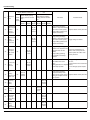
6SHFL¿FDWLRQV
6SHFL¿FDWLRQV
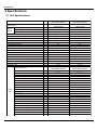
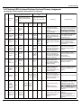
8QLW6SHFL¿FDWLRQV
Rated Voltage
V~
GWH09MB-K3DNA2K
GWH09MB-K3DNA3K
CB181005700
CB171007600
220-240
Rated Frequency
Hz
50
Model
Product Code
Power
Supply
Phases
Power Supply Mode
GWH12MB-K3DNA2K
GWH12MB-K3DNA3K
CB181005800
CB171007700
220-240
50
1
1
Indoor
Indoor
Cooling Capacity (Min~Max)
W
2700(600~3200)
3500(600~3900)
Heating Capacity (Min~Max)
W
2800(800~3600)
4000(880~4400)
Cooling Power Input (Min~Max)
W
870(185~1300)
1170(185~1400)
1200(250~1550)
Heating Power Input (Min~Max)
W
900(220~1400)
Cooling Power Current
A
3.8
5.2
Heating Power Current
A
3.92
5.3
Rated Input
W
1400
1600
Rated Current
A
6.69
7.8
Air Flow Volume(SH/H/M/L/SL)
3
600/500/400/300/-
580/500/400/300/-
Dehumidifying Volume
m /h
L/h
0.8
1.2
EER
W/W
3.10
2.99
COP
W/W
3.11
3.33
SEER
W/W
5.6
6.1
SCOP
W/W
3.8
4.0
m2
12-18
GWH09MB-K3DNA2K/I
GWH09MB-K3DNA3K/I
16-24
GWH12MB-K3DNA2K/I
GWH12MB-K3DNA3K/I
Application Area
Model of Indoor Unit
Fan Type
Diameter Length(DXL)
mm
Φ92X645
Φ92X645
Fan Motor Cooling Speed (SH/H/M/L/SL)
r/min
1260/1050/900/690/-
1290/1070/900/690/-
Fan Motor Heating Speed (SH/H/M/L/SL)
1280/1050/980/920/-
r/min
1320/1200/1000/910/-
Output of Fan Motor
W
20
20
Fan Motor RLA
A
0.1
0.1
Fan Motor Capacitor
μF
1.0
1.0
Input of Heater
W
-
-
Aluminum Fin-copper Tube
Aluminum Fin-copper Tube
Evaporator Form
Indoor
Unit
Pipe Diameter
Coil Length (LXDXW)
mm
Φ7
Φ7
mm
2-1.4
2-1.4
mm
636X25.4X267
636X25.4X267
MP24AA
MP24AA
Swing Motor Model
Output of Swing Motor
W
2
2
Fuse
A
3.15
3.15
Sound Pressure Level (SH/H/M/L/SL)
dB (A)
41/39/34/28/-
42/40/35/30/-
Sound Power Level (SH/H/M/L/SL)
dB (A)
54/50/45/40/-
54/51/45/42/-
mm
845X275X180
845X275X180
Dimension (WXHXD)
Dimension of Carton Box (LXWXH)
mm
915X255X355
915X255X355
Dimension of Package (LXWXH)
mm
918X258X370
918X258X370
Net Weight
kg
9
9
Gross Weight
kg
12
12
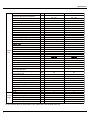
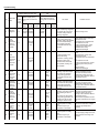
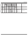
6SHFL¿FDWLRQV
Model of Outdoor Unit
GWH09MB-K3DNA3K/O
GWH12MB-K3DNA3K/O
ZHUHAI LANDA COMPRESSOR ZHUHAI LANDA COMPRESSOR
CO., LTD.
CO., LTD.
QXA-A091zE190A
QXA-A091zE190A
Compressor Manufacturer/Trademark
Compressor Model
Compressor Oil
Compressor Type
L.R.A.
A
FVC 68EP
FVC 68EP
Rotary
Rotary
16.5
16.5
Compressor RLA
A
4.9
4.9
Compressor Power Input
W
950
950
1NT11L-6233
1NT11L-6233
Overload Protector
Throttling Method
Electron expansion valve
Electron expansion valve
Operation temp
ºC
16~30
16~30
Ambient temp (Cooling)
ºC
-7~43
-7~43
Ambient temp (Heating)
ºC
Condenser Form
Pipe Diameter
mm
-7~24
-7~24
Aluminum Fin-copper Tube
Aluminum Fin-copper Tube
Φ7
Φ7
mm
1-1.4
2-1.4
Coil Length (LXDXW)
mm
710X19.05X508
695X38.1X506
Fan Motor Speed
rpm
900/650
900/650
Output of Fan Motor
Outdoor Fan Motor RLA
Unit
Fan Motor Capacitor
Air Flow Volume of Outdoor Unit
W
30
30
A
0.15
0.15
μF
-
-
3
m /h
1800
1800
mm
Φ400
Φ400
Automatic Defrosting
Automatic Defrosting
T1
T1
I
I
IP24
IP24
MPa
4.3
4.3
MPa
2.5
2.5
Fan Type
Fan Diameter
Defrosting Method
Climate Type
Isolation
Moisture Protection
Permissible Excessive Operating Pressure
for the Discharge Side
Permissible Excessive Operating Pressure
for the Suction Side
Sound Pressure Level (H/M/L)
dB (A)
51/-/-
53/-/-
Sound Power Level (H/M/L)
dB (A)
63/-/-
63/-/-
mm
776X540X320
776X540X320
Dimension (WXHXD)
Dimension of Carton Box (LXWXH)
mm
848X360X580
848X360X580
Dimension of Package (LXWXH)
mm
851X363X595
851X363X595
Net Weight
kg
28.0
29.0
Gross Weight
kg
Refrigerant
Refrigerant Charge
Length
Gas Additional Charge
Connectio Outer Diameter Liquid Pipe
n Pipe Outer Diameter Gas Pipe
kg
32.0
33.0
R410A
R410A
0.7
0.85
m
5
5
g/m
20
20
mm
Φ6
Φ6
Φ9.52
mm
Φ9.52
Max Distance Height
m
10
10
Max Distance Length
m
15
15
7KHDERYHGDWDLVVXEMHFWWRFKDQJHZLWKRXWQRWLFH3OHDVHUHIHUWRWKHQDPHSODWHRIWKHXQLW
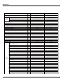
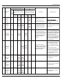
6SHFL¿FDWLRQV
Rated Voltage
V~
GWH09MB-K3DNC9K
GWH09MB-K3DNE1K
CB145003600
CB143001300
220-240
Rated Frequency
Hz
50
Model
Product Code
Power
Supply
Phases
Power Supply Mode
GWH12MB-K3DNC9K
GWH12MB-K3DNE1K
CB145003700
CB143001400
220-240
50
1
1
Indoor
Indoor
Cooling Capacity (Min~Max)
W
2700(600~3200)
3500(600~3900)
Heating Capacity (Min~Max)
W
2800(800~3600)
4000(880~4400)
Cooling Power Input (Min~Max)
W
870(185~1300)
1170(185~1400)
1200(250~1550)
Heating Power Input (Min~Max)
W
900(220~1400)
Cooling Power Current
A
3.8
5.2
Heating Power Current
A
3.92
5.3
Rated Input
W
1400
1600
Rated Current
A
6.69
7.8
Air Flow Volume(SH/H/M/L/SL)
3
600/500/400/300/-
580/500/400/300/-
Dehumidifying Volume
m /h
L/h
0.8
1.2
EER
W/W
3.10
2.99
COP
W/W
3.11
3.33
SEER
W/W
5.6
6.1
SCOP
W/W
3.8
4.0
m2
12-18
GWH09MB-K3DNC9K/I
GWH09MB-K3DNE1K/I
16-24
GWH12MB-K3DNC9K/I
GWH12MB-K3DNE1K/I
Application Area
Model of Indoor Unit
Fan Type
Diameter Length(DXL)
mm
Φ92X645
Φ92X645
Fan Motor Cooling Speed (SH/H/M/L/SL)
r/min
1260/1050/900/690/-
1290/1070/900/690/-
Fan Motor Heating Speed (SH/H/M/L/SL)
1280/1050/980/920/-
r/min
1320/1200/1000/910/-
Output of Fan Motor
W
20
20
Fan Motor RLA
A
0.1
0.1
Fan Motor Capacitor
μF
1.0
1.0
Input of Heater
W
-
-
Aluminum Fin-copper Tube
Aluminum Fin-copper Tube
Evaporator Form
Indoor
Unit
Pipe Diameter
Coil Length (LXDXW)
mm
Φ7
Φ7
mm
2-1.4
2-1.4
mm
636X25.4X267
636X25.4X267
MP24AA
MP24AA
Swing Motor Model
Output of Swing Motor
W
2
2
Fuse
A
3.15
3.15
Sound Pressure Level (SH/H/M/L/SL)
dB (A)
41/39/34/28/-
42/40/35/30/-
Sound Power Level (SH/H/M/L/SL)
dB (A)
54/50/45/40/-
54/51/45/42/-
mm
845X275X180
845X275X180
Dimension (WXHXD)
Dimension of Carton Box (LXWXH)
mm
915X255X355
915X255X355
Dimension of Package (LXWXH)
mm
918X258X370
918X258X370
Net Weight
kg
9
9
Gross Weight
kg
12
12
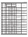
6SHFL¿FDWLRQV
Model of Outdoor Unit
GWH09MB-K3DNA3K/O
GWH12MB-K3DNA3K/O
ZHUHAI LANDA COMPRESSOR ZHUHAI LANDA COMPRESSOR
CO., LTD.
CO., LTD.
QXA-A091zE190A
QXA-A091zE190A
Compressor Manufacturer/Trademark
Compressor Model
Compressor Oil
Compressor Type
L.R.A.
A
FVC 68EP
FVC 68EP
Rotary
Rotary
16.5
16.5
Compressor RLA
A
4.9
4.9
Compressor Power Input
W
950
950
1NT11L-6233
1NT11L-6233
Overload Protector
Throttling Method
Electron expansion valve
Electron expansion valve
Operation temp
ºC
16~30
16~30
Ambient temp (Cooling)
ºC
-7~43
-7~43
Ambient temp (Heating)
ºC
Condenser Form
Pipe Diameter
mm
-7~24
-7~24
Aluminum Fin-copper Tube
Aluminum Fin-copper Tube
Φ7
Φ7
mm
1-1.4
2-1.4
Coil Length (LXDXW)
mm
710X19.05X508
695X38.1X506
Fan Motor Speed
rpm
900/650
900/650
Output of Fan Motor
Outdoor Fan Motor RLA
Unit
Fan Motor Capacitor
Air Flow Volume of Outdoor Unit
W
30
30
A
0.15
0.15
μF
-
-
3
m /h
1800
1800
mm
Φ400
Φ400
Automatic Defrosting
Automatic Defrosting
T1
T1
I
I
IP24
IP24
MPa
4.3
4.3
MPa
2.5
2.5
Fan Type
Fan Diameter
Defrosting Method
Climate Type
Isolation
Moisture Protection
Permissible Excessive Operating Pressure
for the Discharge Side
Permissible Excessive Operating Pressure
for the Suction Side
Sound Pressure Level (H/M/L)
dB (A)
51/-/-
53/-/-
Sound Power Level (H/M/L)
dB (A)
63/-/-
63/-/-
mm
776X540X320
776X540X320
Dimension (WXHXD)
Dimension of Carton Box (LXWXH)
mm
848X360X580
848X360X580
Dimension of Package (LXWXH)
mm
851X363X595
851X363X595
Net Weight
kg
28.0
29.0
Gross Weight
kg
Refrigerant
Refrigerant Charge
Length
Gas Additional Charge
Connectio Outer Diameter Liquid Pipe
n Pipe Outer Diameter Gas Pipe
kg
32.0
33.0
R410A
R410A
0.7
0.85
m
5
5
g/m
20
20
mm
Φ6
Φ6
Φ9.52
mm
Φ9.52
Max Distance Height
m
10
10
Max Distance Length
m
15
15
7KHDERYHGDWDLVVXEMHFWWRFKDQJHZLWKRXWQRWLFH3OHDVHUHIHUWRWKHQDPHSODWHRIWKHXQLW
6SHFL¿FDWLRQV
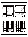
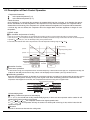
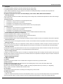
2SHUDWLRQ&KDUDFWHULVWLF&XUYH
Cooling
Heating
8
10
9
7
8
6
12K
12K
7
5
Current(A)
Current(A)
6
09K
5
4
3
Condition
Indoor:DB 27 WB19
Indoor air flow: Turbo
Pipe length:5m
Voltage:230V
2
09K
4
3
Condition
Indoor:DB 20
Indoor air flow:Turbo
Pipe length:5m
Voltage:230V
2
1
1
0
0
0
20
40
60
80
100
0
120
20
Compressor Speed(rps)
40
60
80
100
120
Compressor Speed(rps)
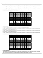
&DSDFLW\9DULDWLRQ5DWLR$FFRUGLQJWR7HPSHUDWXUH
Heating
110
120
100
100
90
80
Capacity ratio(%)
Capacity ratio(%)
Cooling
80
70
60
Condition
Indoor:DB27℃ WB19℃
Indoor air flow: Turbo
Pipe length:5m
50
32 33 34 35 36 37 38 39 40 41 42 43 44 45 46
Outdoor temp. (°C)
60
40
Condition
Indoor:DB20℃
Indoor air flow: Turbo
Pipe length:5m
20
0
-7
-5
0
5
10
Outdoor temp. (°C)
6SHFL¿FDWLRQV
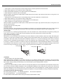
1RLVH&ULWHULD&XUYH7DEOHVIRU%RWK0RGHOV
Indoor side noise when blowing
Outdoor side noise when Compressor speed changed
45
55
Noise/dB(A)
Noise/dB(A)
40
35
30
High
Middle
Low
12K
50
45
20
25
Supper High
09K
30
Indoor fan motor rotating speed
40
50
60
70 75
Compressor Speed(rps)
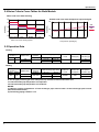
2SHUDWLRQ'DWD
&RROLQJ
7HPSHUDWXUH
FRQGLWLRQć 0RGHOQDPH
,QGRRU 2XWGRRU
.
.
6WDQGDUG
SUHVVXUH
303D
a
+HDWH[FKDQJHUSLSHWHPS
7&
WR
WR
7&
WR
WR
,QGRRUIDQ
PRGH
2XWGRRUIDQ &RPSUHVVRU
PRGHUSP UHYROXWLRQUSV
785%2
+HDWLQJ
7HPSHUDWXUH
FRQGLWLRQć 0RGHOQDPH
,QGRRU 2XWGRRU
.
.
6WDQGDUG
SUHVVXUH
303D
a
+HDWH[FKDQJHUSLSHWHPS
7&
WR
WR
7&
WR
WR
,QGRRUIDQ
PRGH
2XWGRRUIDQ &RPSUHVVRU
PRGHUSP UHYROXWLRQUSV
785%2
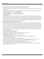
37KHDLUSLSHSUHVVXUHJDVYDOYHVLGHSUHVVXUHFRQQHFWWRLQGRRUDQGRXGRRUXQLW
7,QOHWDQGRXWOHWSLSHWHPSHUDWXUHRIHYDSRUDWRU
7,QOHWDQGRXWOHWSLSHWHPSHUDWXUHRIFRQGHQVHU
127(6
0HDVXUH VXUIDFH WHPSHUDWXUH RI KHDW H[FKDQJHU SLSH DURXQG FHQWHU RI KHDW H[FKDQJHU SDWK 8 EHQW
7KHUPLVWRUWKHPRPHWHU
&RQQHFWLQJSLSLQJFRQGLWLRQP
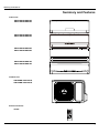
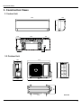
&RQVWUXFWLRQ9LHZV
&RQVWUXFWLRQ9LHZV
,QGRRU8QLW
Φ55
Φ55
143
80
2XWGRRU8QLW
714
320
776
286
540
257
510
8QLWPP
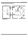
5HIULJHUDQW6\VWHP'LDJUDP
5HIULJHUDQW6\VWHP'LDJUDP
INDOOR UNIT
OUTDOOR UNIT
4-Way valve
HEAT
EXCHANGER
(EVAPORATOR)
Accumlator
Compressor
HEAT
EXCHANGER
(EVAPORATOR)
Strainer Electron expansion valve Strainer
COOLING
HEATING
5HIULJHUDQWSLSHGLDPHWHU
/LTXLGPP
*DVPP
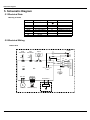
6FKHPDWLF'LDJUDP
6FKHPDWLF'LDJUDP
(OHFWULFDO'DWD
0HDQLQJRIPDUNV
6\PERO
&RORU6\PERO
6\PERO
2*
25$1*(
:+
<(
5'
<(*1
%1
%8
%.
:+,7(
<(//2:
5('
<(//2:*5((1
%52:1
%/8(
%/$&.
3DUWV1DPH
3527(&7,9(($57+
&203
6$7
<9
;7
&2035(6625
29(5/2$'
:$<9$/9(
7(50,1$/%/2&.
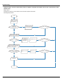
(OHFWULFDO:LULQJ
Ɣ,QGRRU8QLW
TUBE
TEM.SENSOR
θ
θ
RT1
RT2
DISPLAY
L1
AP1
CN1 CN2
L1
N
ROOM
DISP-1 DISP-2
TUBE
COM-OUT
POWER
BN
YEGN
BU
XT1
W1BU
N(1)
W2BK
2
W3BN
CAP
AP2
AC-L
L-OUT
K4
JUMP
3
W4YEGN
L
N
BU
BK
BN
YEGN
OUTDOOR UNIT
ROOM
TEM.SENSOR
EVAPORATOR
PE
PGF PG
SWING-UD
HEALTH-LHEALTH-N
M
M
RD
BU
COOL PLASMA
GENERATOR
YEGN
FAN MOTOR
SWING MOTOR(U.D)
PE
6FKHPDWLF'LDJUDP
Ɣ2XWGRRU8QLW
TUBE OUTROOM EXHAUST
TEM.SENSOR TEM.SENSOR TEM.SENSOR
RT1 RT2 RT3
4YV
θ θ θ
YEGN
PE
I
N
D
O
O
R
U
N
I
T
BU
BK
BN
YEGN
XT
N(1)
2
3
PE
CN2
CN1
CN3
AP1
L1 BU
BK
L1 BN
EKV
L3
BU BN
LX1-1 LX1-2
CN1
AC-L2
4V
AC-L3
AP2
N
COM-OUT N1 BU
AC-L
L
AC-L1 BN
BN
AC-N1
AC-N2 BU
AC-N
AC-L
OFAN
OVC-COMP
U V W
PE
BU YE RD L4
MID.ISOLATION SHEET ELECTRIC BOX
PE
PE
L2
YEGN
SAT
RD
M
L2 L2
NOTE:
FAN
Motor ground only
BU YE RD
applies to the
YEGN
V
U
iron shell motor.
YEGN
W
COMP.
PE
E
COMP
7KHVHFLUFXLWGLDJUDPVDUHVXEMHFWWRFKDQJHZLWKRXWQRWLFHSOHDVHUHIHUWRWKHRQHVXSSOLHGZLWKWKHXQLW
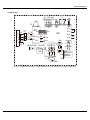
6FKHPDWLF'LDJUDP
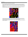
3ULQWHG&LUFXLW%RDUG
,QGRRU8QLW
TOP VIEW
Solid-state relay
Port of neutral wire
Auto button Feedback of indoor fan
Live wire of health function
Port of indoor fan
Port of motor for vertical swing
Port of motor for
horizontal swing
Protective
tube
Buzzer
Port of indoor ambient
temp sensor
Port of indoor pipe
temp sensor
Power of
switch
Port of display
High-frequency transformer
Communication port
Main chip
BOTTOM VIEW
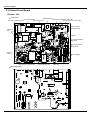
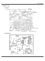
6FKHPDWLF'LDJUDP
2XWGRRU8QLW
Ɣ7239,(:
inductance pin1
inductance pin2
fan neilsbed
four-way valve
compressor
electric heater
chassis
electric heater
10-core
communication cable
compressor
Ɣ%277209,(:
temp. sensor
overload protection
electric expansion valve
)XQFWLRQDQG&RQWURO
)XQFWLRQDQG&RQWURO
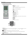
5HPRWH&RQWURO2SHUDWLRQV
1
ON/OFF
Press it to start or stop operation.
2
MODE
Press it to select operation mode (AUTO/COOL/DRY/FAN/HEAT).
3
+
Press it to increase temperature setting.
4
Press it to decrease temperature setting.
5
2
1
FAN
Press it to set fan speed.
6
3
4
6
5
11
12
13
TIMER ON
Press it to set auto-on timer.
7
9
10
Press it to set swing angle.
7
8
TIMER OFF
Press it to set auto-off timer.
8
9
14
CLOCK
Press it to set clock.
10
X-FAN(X-FAN is the alternative expression of BLOW for the purpose
of understanding.)
11
12
13
14
TEMP
TURBO
SLEEP
LIGHT
Press it to turn on/off the light.
25
24
23
22
21
15
16
20
17 18 19
15
MODE icon:
If MODE button is pressed, current operation mode icon
(AUTO),
( COOL),
(DRY),
(FAN) or
(HEAT is only for heat
pump models) will show.
16
SLEEP icon :
is displayed by pressing the SLEEP button. Press this button again to clear the display.
17
TEMP icon:
Pressing TEMP button,
(set temperature),
(indoor ambient temperature),
(outdoor ambient temperature) and blank is
displayed circularly.
18
Up & down swing icon:
is displayed when pressing the up & down swing button. Press this button again to clear the display.
)XQFWLRQDQG&RQWURO
19
LIGHT icon:
is displayed by pressing the LIGHT button.Press LIGHT button again to clear the display.
20
LOCK icon:
is displayed by pressing "+" and “-” buttons simultaneously.Press them again to clear the display.
21
SET TIME display:
After pressing TIMER button, ON or OFF will blink.This area will show the set time.
22
TURBO icon:
23
DIGITAL display:
is displayed when pressing theTURBO button.Press this button again to clear the display.
This area will show the set temperature. During defrosting operation, “H1” will be displayed.
24
X-FAN icon:
25
FAN SPEED display:
is displayed when pressing the X-FAN button. Press this button again to clear the display.
Press FAN button to select the desired fan speed setting(AUTO Low-Med-High).Your selection will be displayed in the LCD windows,
except the AUTO fan speed.
1
ON/OFF:
Press this button to turn on the unit. Press this button again to turn off the unit.
2
MODE:
Each time you press this button,a mode is selected in a sequence that goes from AUTO, COOL,DRY, FAN, and HEAT *, as the
following:
AUTO COOL DRY FAN
HEAT*
*Note: Only for models with heating function.
After energization, AUTO mode is defaulted. In AUTO mode, the set temperature will not be displayed on the LCD, and the unit will
automatically select the suitable operation mode in accordance with the room temperature to make indoor room comfortable.
3
+:
Press this button to increase set temperature. Hold it down for above 2 seconds to rapidly increase set temperature. In AUTO mode,
set temperature is not adjustable.
4
-:
Press this button to decrease set temperature. Hold it down for above . 2 seconds to rapidly decrease set temperature. In AUTO
mode, set temperature is not adjustable.
5
FAN :
This button is used for setting fan speed in the sequence that goes from AUTO,
,
,
to then back to Auto.
AUTO
Low speed
Medium speed
High speed
6
Press this button to set up & down swing angle, which circularly changes as below:
OFF
This remote controller is universal. If any command
indicates the guide louver swings as:
,
or
is sent out, the unit will carry out the command as
)XQFWLRQDQG&RQWURO
7
TIMER ON:
Press this button to initiate the auto-ON timer. To cancel the auto-timer program, simply press this button again. After pressing this
button,
disappears and "ON" blinks . 0 0:00 is displayed for ON time setting. Within 5 seconds, press + or - button to adjust the
time value. Every press of either button changes the time setting by 1 minute. Holding down either button rapidly changes the time
setting by 1 minute and then 10 minutes. Within 5 seconds after setting, press TIMER ON button to confirm.
8
TIMER OFF:
Press this button to initiate the auto-off timer. To cancel the auto-timer program, simply press the button again.TIMER OFF setting is
the same as TIMER ON.
9
CLOCK :
Pressing CLOCK button,
blinks. Within 5 seconds, pressing + or - button adjusts the present time. Holding down either button
above 2 seconds increases or decreases the time by 1 minute every 0.5 second and then by 10 minutes every 0.5 second. During
blinking after setting, press CLOCK button again to confirm the setting, and then
10
will be constantly displayed.
X-FAN:
Pressing X -FAN button in COOL or DRY mode,the icon
is displayed and the indoor fan will continue operation for 10 minutes in
order to dry the indoor unit even though you have turned off the unit.
After energization, X-FAN OFF is defaulted. X-FAN is not available in AUTO, FAN or HEAT mode.
11
TEMP:
Press this button, could select displaying the indoor setting temperature or indoor ambient temperature.When the indoor unit firstly
power on it will display the setting temperature, if the temperature's displaying status is changed from other status to"
",displays
the ambient temperature, 5s later or within 5s, it receives other remote control signal that will return to display the setting temperature. if the users haven't set up the temperature displaying status,that will display the setting temperature.
12
TURBO:
Press this button to activate / deactivate the Turbo function which enables the unit to reach the preset temperature in the shortest
time. In COOL mode, the unit will blow strong cooling air at super high fan speed. In HEAT mode, the unit will blow strong heating air
at super high fan speed.
13
SLEEP:
Press this button to go into the SLEEP operation mode. Press it again to cancel this function. This function is available in COOL,
HEAT (Only for models with heating function) or DRY mode to maintain the most comfortable temperature for you.
14
LIGHT:
Press LIGHT button to turn on the display's light and press this button again to turn off the display's light. If the light is turned on ,
is displayed. If the light is tunrned off,
disappears.
15 Combination of "+" and "-" buttons: About lock
Press "+ " and "-" buttons simultaneously to lock or unlock the keypad. If the remote controller is locked,
case, pressing any button,
is displayed. In this
blinks three times.
16 Combination of "MODE" and "-" buttons:About switch between Fahrenheit and Centigrade At unit OFF, press "MODE" and "- "
buttons simultaneously to switch between ℃ and ℉.
Replacement of Batteries
1.Remove the battery cover plate from the rear of the remote controller.
(As shown in the figure)
2.Take out the old batteries.
3.Insert two new AAA1.5V dry batteries, and pay attention to the polarity.
4. Reinstall the battery cover plate.
★Notes:
●When replacing the batteries, do not use old or different types of batteries.
Otherwise, it may cause malfunction.
●If the remote controller will not be used for a long time,
please remove batteries to prevent batteries from leaking.
●The operation should be performed in its receiving range.
●It should be kept 1m away from the TV set or stereo sound sets.
●If the remote controller does not operate normally, please take the
Sketch map for
replacing batteries
batteries out and reinsert them after 30 seconds. If it still can't operate
properly, replace the batteries.
)XQFWLRQDQG&RQWURO
'HVFULSWLRQRI(DFK&RQWURO2SHUDWLRQ
1. Temperature Parameters
Indoor preset temperature (Tpreset)
Indoor ambient temperature (T amb.)
2. Basic Functions
Once energized, in no case should the compressor be restarted within less than 3 minutes. In the situation that memory
function is available, for the first energization, if the compressor is at stop before de-energization, the compressor will be
started without a 3-minute lag; if the compressor is in operation before de-energization, the compressor will be started with
a 3-minute lag; and once started, the compressor will not be stopped within 6 minutes regardless of changes in room
temperature;
(1)COOL mode
The condition and process of cooling
If Tamb. ≥Tpreset COOL mode will act, the compressor and outdoor fan will run, and the indoor fan will run at the set speed.
If Tamb. ≤Tpreset-2 , the compressor will stop, the outdoor fan will delay 30 seconds to stop, and the indoor fan will run at the set speed.
If Tpreset-2
≤Tamb ≤Tpreset , the unit will keep running in the previous mode.
In this mode, the reversal valve will not be powered on and the temperature setting range is 16
~30 .
Start cooling
Tamb.
Tpreset
Original operating status
Tpreset –2 ˚C
≥ 6 min.
≥ 3 min.
≥ 6 min.
Stop cooling
Compressor
Outdoor fan
Setting fan speed
Indoor fan
Run
Protection function
Overcurrent protection
Stop
If total current is high, the compressor will run in limited frequency. If total current is too high, the compressor will stop, the
outdoor fan will delay 30 seconds to stop, indoor unit will display E5 and outdoor yellow light will blink 5 times.
Antifreezing protection
When the antifreezing protection is detected, the compressor will stop, the outdoor fan will stop after 30 seconds, and the
indoor fan and swing motor will keep running in the original mode. When antifreezing protection is eliminated and the
compressor has stopped for 3 minutes, the compressor will resume running in the original mode.
During antifreeze protection
min
Compressor
Outdoor fan
Preset speed
Indoor fan
Run
Stop
(2) Dehumidifying Mode
Working conditions and process of dehumidifying
If T amb. T preset, the unit will enter cooling and dehumidifying mode, in which case the compressor and the outdoor fan will
operate and the indoor fan will run at low speed.
If T preset -2
T amb. T preset, the compressor remains at its original operation state.
If T amb.< T preset -2 , the compressor will stop, the outdoor fan will stop with a time lag of 30s, and the indoor fan will
operate at low speed.
Protection
Protection is the same as that under the cooling mode.
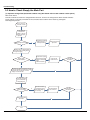
)XQFWLRQDQG&RQWURO
+($70RGH
ķ :RUNLQJFRQGLWLRQVDQGSURFHVVRIKHDWLQJ
,I7DPE7SUHVHW&WKHXQLWHQWHUVKHDWLQJPRGHLQZKLFKFDVHWKHIRXUZD\YDOYHWKHFRPSUHVVRUDQGWKHRXWGRRUIDQZLOO
RSHUDWHVLPXOWDQHRXVO\DQGWKHLQGRRUIDQZLOOUXQDWSUHVHWVSHHGLQWKHFRQGLWLRQRISUHVHWFROGDLUSUHYHQWLRQ
,I7DPE7SUHVHW&WKHFRPSUHVVRUZLOOVWRSWKHRXWGRRUIDQZLOOVWRSZLWKDWLPHODJRIVDQGWKHLQGRRUIDQZLOOVWRSDIWHU
VHFRQGEORZDWORZVSHHG
,I7SUHVHW&7DPE7SUHVHW&WKHXQLWZLOOPDLQWDLQLWVRULJLQDORSHUDWLQJVWDWXV
8QGHUWKLVPRGHWKHIRXUZD\YDOYHLVHQHUJL]HGDQGWHPSHUDWXUHFDQEHVHWZLWKLQDUDQJHRI&7KHRSHUDWLQJV\PEROWKH
KHDWLQJV\PERODQGSUHVHWWHPSHUDWXUHDUHUHYHDOHGRQWKHGLVSOD\
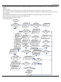
ĸ &RQGLWLRQDQGSURFHVVRIGHIURVW
:KHQGXUDWLRQRIVXFFHVVLYHKHDWLQJRSHUDWLRQLVPRUHWKDQPLQXWHVRUDFFXPXODWHGKHDWLQJWLPHPRUHWKDQPLQXWHVDQG
RQHRIWKHIROORZLQJFRQGLWLRQVLVUHDFKHGWKHXQLWZLOOHQWHUWKHGHIURVWPRGHDIWHUPLQXWHV
7RXWGRRUDPELHQW ˚ &7RXWGRRUWXEH&
&7RXWGRRUDPELHQW ˘ &7RXWGRRUWXEH&
&7RXWGRRUDPELHQW ˘ &7RXWGRRUWXEH&
&7RXWGRRUDPELHQW ˘ &7RXWGRRUWXEH7FRPSHQVDWRU\7RXWGRRUDPELHQW&
7RXWGRRUDPELHQW ˘ &7RXWGRRUWXEH7FRPSHQVDWRU\7RXWGRRUDPELHQW&
DIWHU HQHUJL]LQJ7 FRPSHQVDWRU\ & GXULQJ WKH ILUVW GHIURVWLQJ LI LW LV QRW WKH ILUVW GHIURVWLQJ7 FRPSHQVDWRU\ LV FRQILUPHG E\
7RXWGRRUWXEHRITXLWWLQJODVWGHIURVWLQJDZKHQ7RXWGRRUWXEH ˚ &7FRPSHQVDWRU\ &EZKHQ7RXWGRRUWXEH&7
FRPSHQVDWRU\ &
$WWKDWWLPHWKHLQGRRUIDQVWRSVDQGWKHFRPSUHVVRUVWRSVDQGDIWHUVHFRQGVWKHRXWHUIDQZLOOVWRSDQGWKHQDIWHUVHFRQGV
WKHIRXUZD\YDOYHZLOOVWRS$IWHUVHFRQGVWKHFRPSUHVVRULVLQLWLDWHGIRUUDLVLQJWKHIUHTXHQF\WRGHIURVWIUHTXHQF\
:KHQ WKH FRPSUHVVRU KDV RSHUDWHG XQGHU GHIURVW PRGH IRU PLQXWHV RU7 RXWGRRU DPELHQW ı & WKH FRPSUHVVRU ZLOO EH
FRQYHUWHG WR +] RSHUDWLRQ$IWHU VHFRQGV WKH FRPSUHVVRU ZLOO VWRS$QG DIWHU DQRWKHU VHFRQGV WKH IRXUZD\ YDOYH ZLOO
EH RSHQHG DQG DIWHU VHFRQGV WKH FRPSUHVVRU DQG WKH RXWHU IDQ ZLOO EH VWDUWHG WKH LQGRRU IDQ ZLOO UXQ XQGHU SUHVHW FROG DLU
SUHYHQWLRQFRQGLWLRQVDQG+ZLOOEHGLVSOD\HGDWWHPSHUDWXUHGLVSOD\DUHDRQWKHGLVSOD\SDQHO'HIURVWIUHTXHQF\LV+]
Ĺ 3URWHFWLRQ
ƹ &ROGDLUSUHYHQWLRQ
7KHXQLWLVVWDUWHGXQGHUKHDWLQJPRGHWKHFRPSUHVVRULV21
ķ ,QWKHFDVHRI7LQGRRUDPE&LI7WXEH&DQGWKHLQGRRUIDQLVDWVWRSVWDWHWKHLQGRRUIDQZLOOEHJLQWRUXQDWORZVSHHG
ZLWKDWLPHODJRIPLQXWHV:LWKLQPLQXWHVLI7WXEH!&WKHLQGRRUIDQDOVRZLOOUXQDWORZVSHHGDQGDIWHUPLQXWHRSHUDWLRQ
DWORZVSHHGWKHLQGRRUIDQZLOOEHFRQYHUWHGWRRSHUDWLRQDWSUHVHWVSHHG:LWKLQPLQXWHORZVSHHGRSHUDWLRQRUPLQXWHQRQ
RSHUDWLRQLI7WXEH!&WKHIDQZLOOUXQDWSUHVHQWVSHHG
ĸ ,QWKHFDVHRI7LQGRRUDPE&LI7WXEH&WKHLQGRRUIDQZLOOUXQDWORZVSHHGDQGDIWHURQHPLQXWHWKHLQGRRUIDQZLOO
EHFRQYHUWHGWRSUHVHWVSHHG:LWKLQRQHPLQXWHORZVSHHGRSHUDWLRQLI7WXEH!&WKHLQGRRUIDQZLOOEHFRQYHUWHGWRSUHVHW
VSHHG
1RWH7LQGRRUDPELQGLFDWHGLQ
ķ DQG
ĸ UHIHUVWRXQGHULQLWLDOO\KHDWLQJPRGHWKHLQGRRUDPELHQWWHPSHUDWXUHEHIRUHWKH
FRPPDQG WR VWDUW WKH FRPSUHVVRU LV SHUIRUPHG DFFRUGLQJ WR WKH SURJUDP RU DIWHU WKH XQLW LV ZLWKGUDZQ IURP GHIURVW WKH LQGRRU
DPELHQWWHPSHUDWXUHEHIRUHWKHGHIURVWV\PEROLVFOHDUHG
ƹ 7RWDOFXUUHQWXSDQGIUHTXHQF\GRZQSURWHFWLRQ
,IWKHWRWDOFXUUHQW,WRWDO$IUHTXHQF\ULVHZLOOEHDOORZHGLI,WRWDO$IUHTXHQF\ULVHZLOOQRWEHDOORZHGLI,WRWDO$WKHFRPSUHVVRU
ZLOOUXQDWUHGXFHGIUHTXHQF\DQGLI,WRWDO$WKHFRPSUHVVRUZLOOVWRSDQGWKHRXWGRRUIDQZLOOVWRSZLWKDWLPHODJRIV
)DQ0RGH
8QGHUWKHPRGHWKHLQGRRUIDQZLOOUXQDWSUHVHWVSHHGDQGWKHFRPSUHVVRUWKHRXWGRRUIDQWKHIRXUZD\YDOYHDQGWKHHOHFWULF
KHDWHUZLOOVWRS
8QGHUWKHPRGHWHPSHUDWXUHFDQEHVHWZLWKLQDUDQJHRI&
$8720RGH
ķ :RUNLQJFRQGLWLRQVDQGSURFHVVRI$872PRGH
D:KHQ7DPELHQW&WKHXQLWZLOORSHUDWHLQ&RROPRGH7KHVHWWHPSHUDWXUHLV&
E:KHQ7DPELHQW&WKHKHDWSXPSXQLWZLOORSHUDWHLQ+HDWPRGHVHWWHPSHUDWXUHEH&WKHFRROLQJRQO\XQLWZLOORSHUDWH
LQ)DQPRGHVHWWHPSHUDWXUHEH&
F:KHQ&7DPELHQW&WKHXQLWZLOORSHUDWHLQWKHSUHYLRXVVWDWH,ILWLVHQHUJL]HGIRUWKH¿UVWWLPHLWZLOORSHUDWHLQ)DQ
PRGH
G8QGHUDXWRPRGHLILWVFRROLQJPRGHRSHUDWLRQIUHTXHQF\LVVDPHDVWKDWXQGHUFRROLQJPRGHLILWVKHDWLQJPRGHRSHUDWLRQ
IUHTXHQF\LVVDPHDVWKDWXQGHUKHDWLQJPRGH
)XQFWLRQDQG&RQWURO
ĸ 3URWHFWLRQ
D,QFRROLQJRSHUDWLRQSURWHFWLRQLVWKHVDPHDVWKDWXQGHUWKHFRROLQJPRGH
E,QKHDWLQJRSHUDWLRQSURWHFWLRQLVWKHVDPHDVWKDWXQGHUWKHKHDWLQJPRGH
F:KHQDPELHQWWHPSHUDWXUHFKDQJHVRSHUDWLRQPRGHZLOOEHFRQYHUWHGSUHIHUHQWLDOO\2QFHVWDUWHGWKHFRPSUHVVRUZLOO
UHPDLQXQFKDQJHGIRUDWOHDVWPLQXWHV
&RPPRQ3URWHFWLRQ)XQFWLRQVDQG)DXOW'LVSOD\XQGHU&22/+($7'5<DQG$8720RGHV
ķ 2YHUORDGSURWHFWLRQ
7WXEHPHDVXUHGWHPSHUDWXUHRIRXWGRRUKHDWH[FKDQJHUXQGHUFRROLQJPRGHDQGPHDVXUHGWHPSHUDWXUHRILQGRRUKHDWH[FKDQJHU
XQGHUKHDWLQJPRGH
&RROLQJRYHUORDG
D,I7WXEH&WKHXQLWZLOOUHWXUQWRLWVRULJLQDORSHUDWLRQVWDWH
E,I7WXEH&IUHTXHQF\ULVHLVQRWDOORZHG
F,I7WXEH&WKHFRPSUHVVRUZLOOUXQDWUHGXFHGIUHTXHQF\
G,I7WXEH&WKHFRPSUHVVRUZLOOVWRSDQGWKHLQGRRUIDQZLOOUXQDWSUHVHWVSHHG
+HDWLQJRYHUORDG
D,I7WXEH&WKHXQLWZLOOUHWXUQWRLWVRULJLQDORSHUDWLRQVWDWH
E,I7WXEH&IUHTXHQF\ULVHLVQRWDOORZHG
F,I7WXEH&WKHFRPSUHVVRUZLOOUXQDWUHGXFHGIUHTXHQF\
G,I7WXEH&WKHFRPSUHVVRUZLOOVWRSDQGWKHLQGRRUIDQZLOOEORZUHVLGXHKHDWDQGWKHQVWRS
ĸ ([KDXVWWHPSHUDWXUHSURWHFWLRQRIFRPSUHVVRU
,IH[KDXVWWHPSHUDWXUH&IUHTXHQF\LVQRWDOORZHGWRULVH
,IH[KDXVWWHPSHUDWXUH&WKHFRPSUHVVRUZLOOUXQDWUHGXFHGIUHTXHQF\
,IH[KDXVWWHPSHUDWXUH&WKHFRPSUHVVRUZLOOVWRS
,IH[KDXVWWHPSHUDWXUH&DQGWKHFRPSUHVVRUKDVVWD\HGDWVWRSIRUDWOHDVWPLQXWHVWKHFRPSUHVVRUZLOOUHVXPHLWVRSHUDWLRQ
Ĺ &RPPXQLFDWLRQIDXOW
,IWKHXQLWIDLOVWRUHFHLYHFRUUHFWVLJQDOVIRUGXUDWLYHPLQXWHVFRPPXQLFDWLRQIDXOWFDQEHMXVWL¿HGDQGWKHZKROHV\VWHPZLOOVWRS
ĺ 0RGXOHSURWHFWLRQ
8QGHU PRGXOH SURWHFWLRQ PRGH WKH FRPSUHVVRU ZLOO VWRS :KHQ WKH FRPSUHVVRU UHPDLQV DW VWRS IRU DW OHDVW PLQXWHV WKH
FRPSUHVVRUZLOOUHVXPHLWVRSHUDWLRQ,IPRGXOHSURWHFWLRQRFFXUVVL[WLPHVLQVXFFHVVLRQWKHFRPSUHVVRUZLOOQRWEHVWDUWHGDJDLQ
Ļ 2YHUORDGSURWHFWLRQ
,IWHPSHUDWXUHVHQVHGE\WKHRYHUORDGVHQVRULVRYHU&WKHFRPSUHVVRUZLOOVWRSDQGWKHRXWGRRUIDQZLOOVWRSZLWKDWLPHODJRI
VHFRQGV,IWHPSHUDWXUHLVEHORZ&WKHRYHUORDGSURWHFWLRQZLOOEHUHOLHYHG&
ļ '&EXVYROWDJHSURWHFWLRQ
,IYROWDJHRQWKH'&EXVLVEHORZ9RURYHU9WKHFRPSUHVVRUZLOOVWRSDQGWKHRXWGRRUIDQZLOOVWRSZLWKDWLPHODJRI
VHFRQGV:KHQYROWDJHRQWKH'&EXVUHWXUQVWRLWVQRUPDOYDOXHDQGWKHFRPSUHVVRUKDVVWD\HGDWVWRSIRUDWOHDVWPLQXWHVWKH
FRPSUHVVRUZLOOUHVXPHLWVRSHUDWLRQ
Ľ )DXOWVRIWHPSHUDWXUHVHQVRUV
2WKHU&RQWUROV
212))
3UHVVWKHUHPRWHEXWWRQ212))WKHRQRIIVWDWHZLOOEHFKDQJHGRQFHHDFKWLPH\RXSUHVVWKHEXWWRQ
0RGH6HOHFWLRQ
3UHVVWKHUHPRWHEXWWRQ02'(WKHQVHOHFWDQGVKRZLQWKHIROORZLQJZD\V$872&22/'5<)$1+($7$872
7HPSHUDWXUH6HWWLQJ2SWLRQ%XWWRQ
(DFKWLPH\RXSUHVVWKHUHPRWHEXWWRQ7(03RU7(03WKHVHWWLQJWHPSHUDWXUHZLOOEHXSRUGRZQE\&5HJXODWLQJ
5DQJHa&WKHEXWWRQLVXVHOHVVXQGHUWKH$872PRGH
7LPH6ZLWFK
<RXVKRXOGVWDUWDQGVWRSWKHPDFKLQHDFFRUGLQJWRWKHVHWWLQJWLPHE\UHPRWHFRQWURO
6/((36WDWH&RQWURO
,QFRROLQJPRGH
:KHQWKHLQLWLDOVHWWHPSHUDWXUHLV&WKHWHPSHUDWXUHZLOOULVH&E\HYHU\KRXUDIWHUVOHHSIXQFWLRQLVVHWWKHWHPSHUDWXUH
ZLOOQRWFKDQJHDIWHUULVLQJ&DIWHUUXQQLQJIRUKRXUVWKHWHPSHUDWXUHZLOOGHFUHDVH&DQGLWZLOOQRWFKDQJHDIWHUWKDW
)XQFWLRQDQG&RQWURO
:KHQWKHLQLWLDOVHWWHPSHUDWXUHLV&WKHWHPSHUDWXUHZLOOULVH&E\HYHU\KRXUDIWHUVOHHSIXQFWLRQLVVHWWKHWHPSHUDWXUH
ZLOOQRWFKDQJHDIWHUULVLQJ&DIWHUUXQQLQJIRUKRXUVWKHWHPSHUDWXUHZLOOGHFUHDVH&DQGLWZLOOQRWFKDQJHDIWHUWKDW
:KHQWKHLQLWLDOVHWWHPSHUDWXUHLV&WKHWHPSHUDWXUHZLOOULVH&E\HYHU\KRXUDIWHUVOHHSIXQFWLRQLVVHWWKHWHPSHUDWXUH
ZLOOQRWFKDQJHDIWHUULVLQJ&DIWHUUXQQLQJIRUKRXUVWKHWHPSHUDWXUHZLOOGHFUHDVH&DQGLWZLOOQRWFKDQJHDIWHUWKDW
:KHQ WKH LQLWLDO VHW WHPSHUDWXUH LV & WKH XQLW ZLOO NHHS RQ UXQQLQJ DW WKLV WHPSHUDWXUH DIWHU UXQQLQJ IRU KRXUV WKH
WHPSHUDWXUHZLOOGHFUHDVH&DQGLWZLOOQRWFKDQJHDIWHUWKDW
5HODWLRQVKLSEHWZHHQVHWWHPSHUDWXUHDQGUXQQLQJWLPH
,QLWLDO7HPS
VWDUW
5XQQLQJWLPH7
,QKHDWLQJPRGH
:KHQWKHLQLWLDOVHWWHPSHUDWXUHLV&WKHXQLWZLOONHHSRQUXQQLQJDWWKLVWHPSHUDWXUH
:KHQWKHLQLWLDOVHWWHPSHUDWXUHLV&WKHWHPSHUDWXUHZLOOGHFUHDVH&E\HYHU\KRXUDIWHUVOHHSIXQFWLRQLVVHWWKH
WHPSHUDWXUHZLOOQRWFKDQJHDIWHUGHFUHDVLQJ&
:KHQWKHLQLWLDOVHWWHPSHUDWXUHLV&WKHWHPSHUDWXUHZLOOGHFUHDVH&E\HYHU\KRXUDIWHUVOHHSIXQFWLRQLVVHWWKH
WHPSHUDWXUHZLOOQRWFKDQJHDIWHUGHFUHDVLQJ&
:KHQWKHLQLWLDOVHWWHPSHUDWXUHLV&WKHWHPSHUDWXUHZLOOGHFUHDVH&E\HYHU\KRXUDIWHUVOHHSIXQFWLRQLVVHWWKH
WHPSHUDWXUHZLOOQRWFKDQJHDIWHUGHFUHDVLQJ&
5HODWLRQVKLSEHWZHHQVHWWHPSHUDWXUHDQGUXQQLQJWLPH
,QLWLDO7HPS
VWDUW
5XQQLQJWLPH7
,QGRRU)DQ&RQWURO
7KH,QGRRU)DQFDQEHVHWDV+,*+0('/2:E\UHPRWHFRQWURODQGWKH,QGRRU)DQZLOOEHUHVSHFWLYHO\UXQDWKLJKPHGLXPORZ
VSHHG,WZLOODOVREHVHWDV$872DQGWKH,QGRRU)DQLVDVWKHIROORZLQJVDWWKHDXWRPDWLFZLQGVSHHG
)XQFWLRQDQG&RQWURO
ķ &RROLQJPRGHLQDXWRFRROLQJPRGHRUQRUPDOFRROLQJPRGHWKHDXWRIDQVSHHGZLOOUXQDWEHORZPRGH
D:KHQ7DPE7SUHVHW&WKHLQGRRUIDQZLOOUXQDWKLJKVSHHG
E:KHQ7SUHVHW7DPE7SUHVHW&WKHLQGRRUIDQZLOOUXQDWPLGGOHVSHHG
F7DPE7SUHVHWWKHLQGRRUIDQZLOOUXQDWORZVSHHG
6ZLWFKHV EHWZHHQ KLJK VSHHG DQG PLGGOH VSHHG PLGGOH VSHHG DQG ORZ VSHHG KLJK VSHHG DQG ORZ VSHHG UXQQLQJ WLPH RI PLQXWHVPXVWEHHQVXUHG
ĸ +HDWLQJPRGHLQDXWRKHDWLQJPRGHRUQRUPDOKHDWLQJPRGHWKHDXWRIDQVSHHGZLOOUXQDWEHORZPRGH
D:KHQ7DPE7SUHVHW&WKHLQGRRUIDQZLOOUXQDWKLJKVSHHG
E:KHQ7SUHVHW&7DPE7SUHVHW&WKHLQGRRUIDQZLOOUXQDWPLGGOHVSHHG
F7DPE7SUHVHW&WKHLQGRRUIDQZLOOUXQDWORZVSHHG
6ZLWFKHV EHWZHHQ KLJK VSHHG DQG PLGGOH VSHHG PLGGOH VSHHG DQG ORZ VSHHG KLJK VSHHG DQG ORZ VSHHG UXQQLQJ WLPH RI PLQXWHVPXVWEHHQVXUHG
)DQPRGHLVWKHVDPHDVFRROLQJPRGH
%X]]HU&RQWURO
7KHEX]]HUZLOOVHQGD³'L´VRXQGZKHQWKHDLUFRQGLWLRQHULVSRZHUHGXSRUUHFHLYHGWKHLQIRUPDWLRQVHQWE\WKHUHPRWHFRQWURORU
WKHUHLVDEXWWRQLQSXWWKHVLQJOHWXEHFRROHUGRHVQWUHFHLYHWKHUHPRWHFRQWURO21VLJQDOXQGHUWKHPRGHRIKHDWLQJPRGH
$XWREXWWRQ
,IWKHFRQWUROOHULVRQLWZLOOVWRSE\SUHVVLQJWKHEXWWRQDQGLIWKHFRQWUROOHULVRIILWZLOOEHDXWRPDWLFUXQQLQJVWDWHE\SUHVVLQJWKH
EXWWRQVZLQJRQDQGOLJKWRQDQGWKHPDLQXQLWZLOOUXQEDVHGRQWKHUHPRWHFRQWUROLIWKHUHLVUHPRWHFRQWURORUGHU
8SDQG'RZQ6ZLQJLQJ&RQWURO
:KHQSRZHURQWKHXSDQGGRZQPRWRUZLOO¿UVWO\PRYHWKHDLUGHÀHFWRUWRFRXQWHUFORFNZLVHFORVHWKHDLURXWOHW$IWHUVWDUWLQJWKH
PDFKLQHLI\RXGRQWVHWWKHVZLQJLQJIXQFWLRQKHDWLQJPRGHDQGDXWRKHDWLQJPRGHWKHXSDQGGRZQDLUGHÀHFWRUZLOOPRYHWR
'FORFNZLVHXQGHURWKHUPRGHVWKHXSDQGGRZQDLUGHÀHFWRUZLOOPRYHWR/,I\RXVHWWKHVZLQJLQJIXQFWLRQZKHQ\RXVWDUWWKH
PDFKLQHWKHQWKHZLQGEODGHZLOOVZLQJEHWZHHQ/DQG'7KHDLUGHÀHFWRUKDVVZLQJLQJVWDWHV/RFDWLRQ//RFDWLRQ$/RFDWLRQ
%/RFDWLRQ&/RFDWLRQ'/RFDWLRQ/WR/RFDWLRQ'VWRSDWDQ\ORFDWLRQEHWZHHQ/'WKHLQFOXGHGDQJOHEHWZHHQ/a'LVWKHVDPH
7KHDLUGHÀHFWRUZLOOEHFORVHGDW/RFDWLRQDQGWKHVZLQJLQJLVHIIHFWXDORQO\RQFRQGLWLRQWKDWVHWWLQJWKHVZLQJLQJRUGHUDQGWKH
LQQHUIDQLVUXQQLQJ7KHLQGRRUIDQDQGFRPSUHVVRUPD\JHWWKHSRZHUZKHQDLUGHÀHFWRULVRQWKHGHIDXOWORFDWLRQ
heating angle
O(0 )
R
cooling angle
R
O(0 )
L
A
B
C
L1
A1
B1
C1
D1
D
'LVSOD\
ķ 2SHUDWLRQSDWWHUQDQGPRGHSDWWHUQGLVSOD\
$OOWKHGLVSOD\SDWWHUQVZLOOGLVSOD\IRUDWLPHZKHQWKHSRZHURQWKHRSHUDWLRQLQGLFDWLRQSDWWHUQZLOOGLVSOD\LQUHGXQGHUVWDQGE\
VWDWXV:KHQWKHPDFKLQHLVVWDUWE\UHPRWHFRQWUROWKHLQGLFDWLRQSDWWHUQZLOOOLJKWDQGGLVSOD\WKHFXUUHQWRSHUDWLRQPRGHWKHPRGH
OLJKWLQFOXGHV&RROLQJKHDWLQJDQGGHKXPLGLI\,I\RXFORVHWKHOLJKWNH\DOOWKHGLVSOD\SDWWHUQVZLOOFORVH
ĸ'RXEOHGLVSOD\
$FFRUGLQJWRWKHGLIIHUHQWVHWWLQJRIUHPRWHFRQWUROWKHQL[LHOLJKWPD\GLVSOD\WKHFXUUHQWWHPSHUDWXUHWKHWHPSHUDWXUHVFRSHLVIURP
&WR&DQGLQGRRUDPELHQWWHPSHUDWXUH7KHVHWWHPSHUDWXUHGLVSOD\HGLQDXWRFRROLQJDQGIDQPRGHLV&DQGWKHVHW
WHPSHUDWXUHGLVSOD\HGLQDXWRKHDWLQJPRGHLV&8QGHUKHDWLQJPRGHQL[LHWXEHGLVSOD\V+RUKHDWLQJLQGLFDWRULVRIIVDQG
EOLQNVVLQGHIURVWLQJ,I\RXVHWWKHIDKUHQKHLWWHPSHUDWXUHGLVSOD\WKHQL[LHOLJKWZLOOGLVSOD\DFFRUGLQJWRIDKUHQKHLWWHPSHUDWXUH
3URWHFWLRQIXQFWLRQDQGIDLOXUHGLVSOD\
()UHH]HSURR¿QJSURWHFWLRQ(([KDXVWLQJSURWHFWLRQ(2YHUFXUUHQWSURWHFWLRQ
(&RPPXQLFDWLRQIDLOXUH+2YHUORDGSURWHFWLRQ
),QGRRUDPELHQWVHQVRUVWDUWDQGVKRUWFLUFXLWFRQWLQXRXVO\PHDVXUHGIDLOXUHLQ6
)XQFWLRQDQG&RQWURO
),QGRRUHYDSRUDWRUVHQVRUVWDUWDQGVKRUWFLUFXLWFRQWLQXRXVO\PHDVXUHGIDLOXUHLQ6
)2XWGRRUDPELHQWVHQVRUVWDUWDQGVKRUWFLUFXLWFRQWLQXRXVO\PHDVXUHGIDLOXUHLQ6
)2XWGRRUFRQGHQVHUVHQVRUVWDUWDQGVKRUWFLUFXLWFRQWLQXRXVO\PHDVXUHGIDLOXUHLQ6DQGGRQWPHDVXUHZLWKLQPLQXWHV
DIWHUGHIURVWHG
)2XWGRRUH[KDXVWLQJVHQVRUVWDUWDQGVKRUWFLUFXLWFRQWLQXRXVO\PHDVXUHGIDLOXUHLQ6DIWHUWKHFRPSUHVVRURSHUDWHGPLQXWHV
+2YHUORDGSURWHFWLRQRIFRPSUHVVRU+0RGXOHSURWHFWLRQ
3++LJKYROWDJHSURWHFWLRQ3//RZYROWDJHSURWHFWLRQ
31RPLQDOFRROLQJDQGKHDWLQJ30D[LPXPFRROLQJDQGKHDWLQJ
30HGLXPFRROLQJDQGKHDWLQJ30LQLPXPFRROLQJDQGKHDWLQJ
'U\LQJ)XQFWLRQ
<RXPD\VWDUWRUVWRSWKHGU\LQJIXQFWLRQXQGHUWKHPRGHVRIFRROLQJDQGGHKXPLGLI\DWWKHVWDUWLQJVWDWXV7KHPRGHVRIDXWRPDWLVP
KHDWLQJDQGDLUVXSSO\GRQRWKDYHGU\LQJIXQFWLRQ:KHQ\RXVWDUWWKHGU\LQJIXQFWLRQDIWHUVWRSWKHPDFKLQHE\SUHVVLQJWKHVZLWFK
EXWWRQ\RXVKRXOGNHHSUXQQLQJWKHLQQHUIDQVIRUPLQXWHVXQGHUORZDLUGDPSHU7KHVZLQJZLOORSHUDWHDVWKHIRUPHUVWDWXVZLWKLQ
PLQXWHVFRROLQJLQGLFDWRULVRQIRUVDQGWKHQRIIIRUVLQGU\LQJDQGRWKHUORDGLVVWRSSHGWKHQVWRSWKHHQWLUHPDFKLQH
:KHQ \RX VWRS WKH GU\LQJ IXQFWLRQ SUHVV WKH VZLWFK EXWWRQ ZLOO VWRS WKH PDFKLQH GLUHFWO\ :KHQ \RX VWDUW WKH GU\LQJ IXQFWLRQ
RSHUDWLQJWKHGU\LQJEXWWRQZLOOVWRSWKHLQQHUIDQVDQGFORVHWKHJXLGHORXYHU
0HPRU\IXQFWLRQZKHQLQWHUUXSWLQJWKHSRZHUVXSSO\
0HPRU\FRQWHQWPRGHVZLQJIXQFWLRQOLJKWVHWWHPSHUDWXUHDQGZLQGVSHHG$IWHULQWHUUXSWHGWKHSRZHUVXSSO\WKHPDFKLQHZLOO
VWDUWZKHQUHFRYHULQJWKHSRZHUDFFRUGLQJWRWKHPHPRU\FRQWHQWDXWRPDWLFDOO\,IWKHODVWUHPRWHFRQWUROFRPPDQGKDVQRWVHW
WKHWLPHGIXQFWLRQWKHV\VWHPZLOOUHPHPEHUWKHODVWUHPRWHFRQWUROFRPPDQGDQGRSHUDWHDFFRUGLQJLW,IWKHODVWUHPRWHFRQWURO
FRPPDQGKDVVHWWLPHGIXQFWLRQDQGWKHSRZHUVXSSO\LVLQWHUUXSWHGEHIRUHWKHWLPHGWLPHWKHV\VWHPZLOOUHPHPEHUWKHWLPHG
IXQFWLRQRIWKHODVWUHPRWHFRQWUROFRPPDQGWKHWLPHGWLPHZLOOUHFRXQWHGIRUPSRZHURQ,IWKHODVWUHPRWHFRQWUROFRPPDQGKDV
VHWWLPHGIXQFWLRQWKHWLPHLVRXWDQGWKHV\VWHPLVVWDUWRUVWRSDFFRUGLQJWRWKHVHWWLPHZKHQWKHSRZHUVXSSO\LVLQWHUUXSWHGWKH
V\VWHPZLOOUHPHPEHUWKHRSHUDWLRQVWDWXVEHIRUHWKHSRZHUVXSSO\ZDVLQWHUUXSWHGDQGGRQRWFDUU\RXWWLPHGDFWLRQ7KHWLPHG
FORFNZLOOQRWUHPHPEHUHG
(OHFWULFKHDWLQJEDQGFRQWURORIRXWGRRUXQLW
ķ &RPSUHVVRUHOHFWULFKHDWLQJEDQGFRQWURO
D6WDUWFRQGLWLRQWKHFRPSUHVVRULVLQRIIVWDWXVDQGWKHRXWGRRUDPELHQWWHPSHUDWXUH&
E6WRSFRQGLWLRQWKHEDQGLVRIIZKHQHLWKHURIWKHEHORZFRQGLWLRQLVPHW
7KHFRPSUHVVRULVLQRQVWDWXV
7KHFRPSUHVVRULVLQRIIVWDWXVDQGWKHRXWGRRUDPELHQWWHPSHUDWXUH&
F:KHQRXWGRRUDPELHQWWHPSHUDWXUHVHQVRULVLQPDOIXQFWLRQVWDWXVWKHHOHFWULFKHDWLQJEDQGVWRSVRSHUDWLRQ
ĸ &RQGHQVHUHOHFWULFKHDWLQJEDQGFRQWURO
:KHQ7RXWGRRUDPELHQW&WKHHOHFWULFKHDWLQJEDQGVWDUWVZRUNLQJ
:KHQHQWHUGHIURVWLQJDQGGHIURVWLQJLV¿QLVKHGWKHFKDVVLVHOHFWULFKHDWLQJEDQGVWDUWVZRUNLQJIRUPLQDVWKHFRPSUHVVRU
VWDUWV$IWHUWKHFRPSUHVVRUVWDUWVIRUPLQDQG7RXWGRRUDPELHQW&WKHHOHFWULFKHDWLQJEDQGVWRSVRSHUDWLRQ
:KHQ7RXWGRRUDPELHQW&WKHFRQGHQVHUHOHFWULFKHDWLQJEDQGGRHVQ¶WZRUN
:KHQ&7RXWGRRUDPELHQW&WKHFRQGHQVHUHOHFWULFKHDWLQJEDQGNHHSVWKHSUHYLRXVVWDWXV
:KHQRXWGRRUDPELHQWWHPSHUDWXUHVHQVRULVLQPDOIXQFWLRQVWDWXVWKHHOHFWULFKHDWLQJEDQGVWRSVRSHUDWLRQWKHHOHFWULFKHDWLQJ
EDQGFDQZRUNDJDLQDIWHUPLQRIODVWVWRS
,QVWDOODWLRQ0DQXDO
,QVWDOODWLRQ0DQXDO
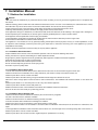
1RWLFHVIRU,QVWDOODWLRQ
&DXWLRQ
7KHXQLWVKRXOGEHLQVWDOOHGRQO\E\DXWKRUL]HGVHUYLFHFHQWHUDFFRUGLQJWRORFDORUJRYHUQPHQWUHJXODWLRQVDQGLQFRPSOLDQFHZLWK
WKLVPDQXDO
%HIRUHLQVWDOOLQJSOHDVHFRQWDFWZLWKORFDODXWKRUL]HGPDLQWHQDQFHFHQWHU,IWKHXQLWLVQRWLQVWDOOHGE\WKHDXWKRUL]HGVHUYLFHFHQWHU
WKHPDOIXQFWLRQPD\QRWEHVROYHGGXHWRLQFRYHQLHQWFRQWDFWEHWZHHQWKHXVHUDQGWKHVHUYLFHSHUVRQQHO
:KHQUHPRYLQJWKHXQLWWRWKHRWKHUSODFHSOHDVH¿UVWO\FRQWDFWZLWKWKHORFDODXWKRUL]HGVHUYLFHFHQWHU
:DUQLQJ%HIRUHREWDLQLQJDFFHVVWRWHUPLQDOVDOOVXSSO\FLUFXLWVPXVWEHGLVFRQQHFWHG
)RUDSSOLDQFHVZLWKW\SH<DWWDFKPHQWWKHLQVWUXFWLRQVVKDOOFRQWDLQWKHVXEVWDQFHRIWKHIROORZLQJ,IWKHVXSSO\FRUGLVGDPDJHGLW
PXVWEHUHSODFHGE\WKHPDQXIDFWXUHULWVVHUYLFHDJHQWRUVLPLODUO\TXDOL¿HGSHUVRQVLQRUGHUWRDYRLGDKD]DUG
7KHDSSOLDQFHPXVWEHSRVLWLRQHGVRWKDWWKHSOXJLVDFFHVVLEOH
7KHWHPSHUDWXUHRIUHIULJHUDQWOLQHZLOOEHKLJKSOHDVHNHHSWKHLQWHUFRQQHFWLRQFDEOHDZD\IURPWKHFRSSHUWXEH
7KHLQVWUXFWLRQVVKDOOVWDWHWKHVXEVWDQFHRIWKHIROORZLQJ
7KLV DSSOLDQFH LV QRW LQWHQGHG IRU XVH E\ SHUVRQVLQFOXGLQJ FKLOGUHQZLWK UHGXFHG SK\VLFDO VHQVRU\ RU PHQWDO FDSDELOLWLHV RU ODFN
RIH[SHULHQFHDQGNQRZOHGJHXQOHVVWKH\KDYHEHHQJLYHQVXSHUYLVLRQRULQVWUXFWLRQFRQFHUQLQJXVHRIWKHDSSOLDQFHE\DSHUVRQ
UHVSRQVLEOHIRUWKHLUVDIHW\
&KLOGUHQVKRXOGEHVXSHUYLVHGWRHQVXUHWKDWWKH\GRQRWSOD\ZLWKWKHDSSOLDQFH
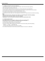
,QVWDOODWLRQ6LWH,QVWUXFWLRQV
3URSHULQVWDOODWLRQVLWHLVYLWDOIRUFRUUHFWDQGHI¿FLHQWRSHUDWLRQRIWKHXQLW$YRLGWKHIROORZLQJVLWHVZKHUH
ƔVWURQJKHDWVRXUFHVYDSRXUVÀDPPDEOHJDVRUYRODWLOHOLTXLGVDUHHPLWWHG
ƔKLJKIUHTXHQF\HOHFWURPDJQHWLFZDYHVDUHJHQHUDWHGE\UDGLRHTXLSPHQWZHOGHUVDQGPHGLFDOHTXLSPHQW
ƔVDOWODGHQDLUSUHYDLOVVXFKDVFORVHWRFRDVWDODUHDV
ƔWKHDLULVFRQWDPLQDWHGZLWKLQGXVWULDOYDSRXUVDQGRLOV
ƔWKHDLUFRQWDLQVVXOSKXUHVJDVVXFKDVLQKRWVSULQJ]RQHV
ƔFRUURVLRQRUSRRUDLUTXDOLW\H[LVWV
,QVWDOODWLRQ6LWHRI,QGRRU8QLW
7KHDLULQOHWDQGRXWOHWVKRXOGEHDZD\IURPWKHREVWUXFWLRQV(QVXUHWKHDLUFDQEHEORZQWKURXJKWKHZKROHURRP
6HOHFWDVLWHZKHUHWKHFRQGHQVDWHFDQEHHDVLO\GUDLQHGRXWDQGZKHUHLWLVHDVLO\FRQQHFWHGWRRXWGRRUXQLW
6HOHFWDSODFHZKHUHLWLVRXWRIUHDFKRIFKLOGUHQ
6HOHFWDSODFHZKHUHWKHZDOOLVVWURQJHQRXJKWRZLWKVWDQGWKHIXOOZHLJKWDQGYLEUDWLRQRIWKHXQLW
%HVXUHWROHDYHHQRXJKVSDFHWRDOORZDFFHVVIRUURXWLQHPDLQWHQDQFH7KHLQVWDOODWLRQVLWHVKRXOGEHFPRUPRUHDERYHWKH
ÀRRU
6HOHFWDSODFHDERXWPRUPRUHDZD\IURP79VHWRUDQ\RWKHUHOHFWULFDSSOLDQFH
6HOHFWDSODFHZKHUHWKH¿OWHUFDQEHHDVLO\WDNHQRXW
0DNHVXUHWKDWWKHLQGRRUXQLWLVLQVWDOOHGLQDFFRUGDQFHZLWKLQVWDOODWLRQGLPHQVLRQLQVWUXFWLRQV
'RQRWXVHWKHXQLWLQWKHODXQGU\RUE\VZLPPLQJSRROHWF
,QVWDOODWLRQ6LWHRI2XWGRRU8QLW
6HOHFWDVLWHZKHUHQRLVHDQGRXWÀRZDLUHPLWWHGE\WKHXQLWZLOOQRWDQQR\QHLJKERUV
6HOHFWDVLWHZKHUHWKHUHLVVXI¿FLHQWYHQWLODWLRQ
6HOHFWDVLWHZKHUHWKHUHLVQRREVWUXFWLRQEORFNLQJWKHLQOHWDQGRXWOHW
7KHVLWHVKRXOGEHDEOHWRZLWKVWDQGWKHIXOOZHLJKWDQGYLEUDWLRQ
6HOHFWDGU\SODFHEXWGRQRWH[SRVHWKHXQLWWRGLUHFWVXQOLJKWRUVWURQJZLQG
0DNHVXUHWKDWWKHRXWGRRUXQLWLVLQVWDOOHGLQDFFRUGDQFHZLWKWKHLQVWDOODWLRQLQVWUXFWLRQVDQGLVFRQYHQLHQWIRUPDLQWHQDQFHDQG
UHSDLU
7KHKHLJKWGLIIHUHQFHEHWZHHQLQGRRUDQGRXWGRRUXQLWVLVZLWKLQPDQGWKHOHQJWKRIWKHFRQQHFWLQJWXELQJGRHVQRWH[FHHGP
6HOHFWDSODFHZKHUHLWLVRXWRIUHDFKRIFKLOGUHQ
6HOHFWDSODFHZKHUHWKHXQLWGRHVQRWKDYHQHJDWLYHLPSDFWRQSHGHVWULDQVRURQWKHFLW\
,QVWDOODWLRQ0DQXDO
6DIHW\3UHFDXWLRQVIRU(OHFWULF$SSOLDQFHV
$GHGLFDWHGSRZHUVXSSO\FLUFXLWVKRXOGEHXVHGLQDFFRUGDQFHZLWKORFDOHOHFWULFDOVDIHW\UHJXODWLRQV
'RQ WGUDJWKHSRZHUFRUGZLWKH[FHVVLYHIRUFH
7KHXQLWVKRXOGEHUHOLDEO\HDUWKHGDQGFRQQHFWHGWRDQH[FOXVLYHHDUWKGHYLFHE\WKHSURIHVVLRQDOV
7KHDLUVZLWFKPXVWKDYHWKHIXQFWLRQVRIPDJQHWLFWULSSLQJDQGKHDWWULSSLQJWRSUHYHQWVKRUWFLUFXLWDQGRYHUORDG
7KHPLQLPXPGLVWDQFHEHWZHHQWKHXQLWDQGFRPEXVWLYHVXUIDFHLVP
7KHDSSOLDQFHVKDOOEHLQVWDOOHGLQDFFRUGDQFHZLWKQDWLRQDOZLULQJUHJXODWLRQV
$QDOOSROHGLVFRQQHFWLRQVZLWFKZLWKDFRQWDFWVHSDUDWLRQRIDWOHDVWPPLQDOOSROHVVKRXOGEHFRQQHFWHGLQ¿[HGZLULQJ
1RWH
Ɣ0DNHVXUHWKHOLYHZLUHQHXWUDOZLUHDQGHDUWKZLUHLQWKHIDPLO\SRZHUVRFNHWDUHSURSHUO\
FRQQHFWHG7KHUHVKRXOGEHUHOLDEOHFLUFXLWLQWKHGLDJUDP
Ɣ,QDGHTXDWHRULQFRUUHFWHOHFWULFDOFRQQHFWLRQVPD\FDXVHHOHFWULFVKRFNRU¿UH
(DUWKLQJ5HTXLUHPHQWV
$LUFRQGLWLRQHULVW\SH,HOHFWULFDSSOLDQFH3OHDVHHQVXUHWKDWWKHXQLWLVUHOLDEO\HDUWKHG
7KH\HOORZJUHHQZLUHLQDLUFRQGLWLRQHULVWKHHDUWKLQJZLUHZKLFKFDQQRWEHXVHG
IRURWKHUSXUSRVHV,PSURSHUHDUWKLQJPD\FDXVHHOHFWULFVKRFN
7KHHDUWKUHVLVWDQFHVKRXOGDFFRUGWRWKHQDWLRQDOFULWHULRQ
7KHSRZHUPXVWKDYHUHOLDEOHHDUWKLQJWHUPLQDO3OHDVHGRQRWFRQQHFWWKHHDUWKLQJZLUHZLWKWKHIROORZLQJ
ķ :DWHUSLSHĸ *DVSLSHĹ &RQWDPLQDWLRQSLSH
ĺ 2WKHUSODFHWKDWSURIHVVLRQDOSHUVRQQHOFRQVLGHULVXQUHOLDEOH
7KHPRGHODQGUDWHGYDOXHVRIIXVHVVKRXOGDFFRUGZLWKWKHVLONSULQWRQIXVHFRYHURUUHODWHG3&%
,QVWDOODWLRQ0DQXDO
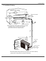
,QVWDOODWLRQ'UDZLQJ
Space to the ceiling
15cm
Above
Space to the wall
15cm Above
15cm Above
Space to the wall
300cm
cm
Above
Above
Air outlet side
Space to the floor
Space to the obstruction
50cm Above
The dimensions of the space necessary for proper
installation of the unit include the minimum
permissible distances to adjacent parts.
Air inlet side
ov
cm
30cm Above
Ab
e
30
Space to the wall
0
20
cm
o
Ab
ve
Space to the wall
50cm Above
Air outlet side
Schematic diagram being reference only (outdoor unit is with variation),
please refer to real product for authentic information.
,QVWDOODWLRQ0DQXDO
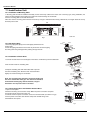
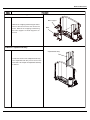
,QVWDOO,QGRRU8QLW
,QVWDOODWLRQRI0RXQWLQJ3ODWH
0RXQWLQJSODWHVKRXOGEHLQVWDOOHGKRUL]RQWDOO\$VWKHZDWHUWUD\VRXWOHWIRUWKHLQGRRUXQLWLVWZRZD\W\SHGXULQJLQVWDOODWLRQWKH
LQGRRUXQLWVKRXOGVOLJKWO\VODQWWRZDWHUWUD\VRXWOHWIRUVPRRWKGUDLQDJHRIFRQGHQVDWH
)L[WKHPRXQWLQJSODWHRQWKHZDOOZLWKVFUHZV
%HVXUHWKDWWKHPRXQWLQJSODWHKDVEHHQ¿[HG¿UPO\HQRXJKWRZLWKVWDQGDERXWNJ0HDQZKLOHWKHZHLJKWVKRXOGEHHYHQO\
VKDUHGE\HDFKVFUHZ
Wall
Above 150 from the ceiling
Wall
Wall
Above
150 from
the wall
Above
150 from
the wall
Φ55
Φ55
Left
)LJ
'ULOO3LSLQJ+ROH
6ODQWWKHSLSLQJKROHĭRQWKHZDOOVOLJKWO\GRZQZDUGWRWKH
RXWGRRUVLGH
,QVHUWWKHSLSLQJKROHVOHHYHLQWRWKHKROHWRSUHYHQWWKHFRQQHFWLRQSLSLQJ
DQGZLULQJIURPEHLQJGDPDJHGZKHQSDVVLQJWKURXJKWKHKROH
Right
Indoor
8QLWPP
Outdoor
Wall pipe
Seal pad
ĭ
,QVWDOODWLRQRI'UDLQ+RVH
&RQQHFWWKHGUDLQKRVHWRWKHRXWOHWSLSHRIWKHLQGRRUXQLW%LQGWKHMRLQWZLWKUXEEHUEHOW
3XWWKHGUDLQKRVHLQWRLQVXODWLQJWXEH
outlet pipe of
indoor unit
rubber belt
outlet pipe of
indoor unit
drain hose
outlet pipe of
indoor unit
:UDSWKHLQVXODWLQJWXEHZLWKZLGHUXEEHUEHOWWRSUHYHQW
WKHVKLIWRILQVXODWLQJWXEH6ODQWWKHGUDLQKRVHGRZQZDUG
VOLJKWO\IRUVPRRWKGUDLQDJHRIFRQGHQVDWH
1RWH7KHLQVXODWLQJWXEHVKRXOGEHFRQQHFWHGUHOLDEO\ZLWK
WKHVOHHYHRXWVLGHWKHRXWOHWSLSH7KHGUDLQKRVHVKRXOGEH
VODQWHGGRZQZDUGVOLJKWO\ZLWKRXWGLVWRUWLRQEXOJHRU
ÀXFWXDWLRQ'RQRWSXWWKHRXWOHWLQWKHZDWHU
drain hose
rubber belt insulating tube
rubber belt
outlet pipe of
indoor unit
connected
bulge
insulating tube
distortion
Flooded
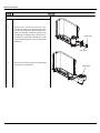
&RQQHFWLQJ,QGRRUDQG2XWGRRU(OHFWULF:LUHV
2SHQWKHIURQWSDQHO
5HPRYHWKHZLULQJFRYHUDQGZLUHFODPS0DNHWKHSRZHUFRQQHFWLRQFRUGSDVV
WKURXJKWKHKROHDWWKHEDFNRILQGRRUXQLW
&RQQHFWDQG¿[WKHSRZHUFRQQHFWLRQFRUGWRWKHWHUPLQDOERDUG$VVKRZQLQ)LJ
)L[WKHSRZHUFRQQHFWLRQFRUGZLWKZLUHFODPSDQGUHLQVWDOOZLULQJFRYHU
5HLQVWDOOWKHIURQWSDQHO
Wiring Cover
N(1)
blue black
2
3
brown
yellowgreen
outdoor unit connection
Fig.2
,QVWDOODWLRQ0DQXDO
127(
$OOZLUHVEHWZHHQLQGRRUDQGRXWGRRUXQLWVPXVWEHFRQQHFWHGE\WKHTXDOL¿HGHOHFWULFFRQWUDFWRU
Ɣ(OHFWULFZLUHVPXVWEHFRQQHFWHGFRUUHFWO\,PSURSHUFRQQHFWLRQPD\FDXVHPDOIXQFWLRQ
Ɣ7LJKWHQWKHWHUPLQDOVFUHZVVHFXUHO\
Ɣ$IWHUWLJKWHQLQJWKHVFUHZVSXOOWKHZLUHVOLJKWO\WRFRQ¿UPZKHWKHULWV¿UPRUQRW
Ɣ0DNHVXUHWKDWWKHHOHFWULFFRQQHFWLRQVDUHHDUWKHGSURSHUO\WRSUHYHQWHOHFWULFVKRFN
Ɣ0DNHVXUHWKDWDOOZLULQJFRQQHFWLRQVDUHVHFXUHDQGWKHFRYHUSODWHVDUHUHLQVWDOOHGSURSHUO\3RRULQVWDOODWLRQPD\FDXVH¿UHRU
HOHFWULFVKRFN
Gas side pipe
,QVWDOODWLRQRI,QGRRU8QLW
Ɣ7KHSLSLQJFDQEHRXWSXWIURPULJKWULJKWUHDUOHIWRUOHIWUHDU
:KHQURXWLQJWKHSLSLQJDQGZLULQJIURPWKHOHIWRUULJKWVLGHRILQGRRUXQLWFXWRIIWKHWDLOLQJV
IURPWKHFKDVVLVZKHQQHFHVVDU\$VVKRZQLQ)LJ
Ł &XWRIIWDLOLQJZKHQURXWLQJWKHZLULQJRQO\
ł &XWRIIWDLOLQJDQGWDLOLQJZKHQURXWLQJERWKWKHZLULQJDQGSLSLQJ
7DNHRXWWKHSLSLQJIURPERG\FDVHZUDSWKHSLSLQJSRZHUFRUGVGUDLQKRVHZLWKWKHWDSH
DQGWKHQPDNHWKHPSDVVWKURXJKWKHSLSLQJKROH$VVKRZQLQ)LJ
+DQJWKHPRXQWLQJVORWVRIWKHLQGRRUXQLWRQWKHXSSHUKRRNVRIWKHPRXQWLQJSODWHDQG
FKHFNLILWLV¿UPHQRXJK$VVKRZQLQ)LJ
7KHLQVWDOODWLRQVLWHVKRXOGEHFPRUPRUHDERYHWKHÀRRU
Tailing 2
Tailing 1
Fig.3
External connection
electric wire
Liquid side piping
Gas side piping
insulation
Liquid side
Piping insulation
Finally wrap it
Water drainage pipe
with tape
Left
েৢ
Left rear
Right
Right rear
Fig.4
Fixing hook
Mounting
plate
Mounting
plate
Fig.5
,QVWDOODWLRQRI&RQQHFWLRQ3LSH
$OLJQWKHFHQWHURIWKHSLSHÀDUHZLWKWKHUHODWHGYDOYH
6FUHZLQWKHÀDUHQXWE\KDQGDQGWKHQWLJKWHQWKHQXWZLWKVSDQQHUDQGWRUTXH
ZUHQFKE\UHIHUULQJWRWKHIROORZLQJ
+H[QXWGLDPHWHU
Ɏ
Ɏ
Ɏ
Ɏ
Ɏ
7LJKWHQLQJWRUTXH1ÂP
̚
̚
̚
̚
̚
127(&RQQHFWWKHFRQQHFWLRQSLSHWRLQGRRUXQLWDW¿UVWDQGWKHQWRRXWGRRUXQLW
+DQGOHSLSLQJEHQGLQJZLWKFDUH'RQRWGDPDJHWKHFRQQHFWLRQSLSH(QVXUHWKDW
WKHMRLQWQXWLVWLJKWHQHG¿UPO\RWKHUZLVHLWPD\FDXVHOHDNDJH
Indoor unit piping
Taper nut Piping
Spanner
Torque
wrench
,QVWDOO2XWGRRU8QLW
(OHFWULF:LULQJ
5HPRYHWKHKDQGOHRQWKHULJKWVLGHSODWHRIRXWGRRUXQLW
7DNHRIIZLUHFODPS&RQQHFWDQG¿[WKHSRZHUFRQQHFWLRQFRUG
WRWKHWHUPLQDOERDUG:LULQJVKRXOG¿WWKDWRILQGRRUXQLW
)L[WKHSRZHUFRQQHFWLRQFRUGZLWKZLUHFODPS
&RQ¿UPLIWKHZLUHKDVEHHQ¿[HGSURSHUO\
5HLQVWDOOWKHKDQGOH
127(
Ɣ,QFRUUHFWZLULQJPD\FDXVHPDOIXQFWLRQRIVSDUHSDUW
Ɣ$IWHUWKHZLUHKDVEHHQ¿[HGHQVXUHWKHUHLVIUHH
VSDFHEHWZHHQWKHFRQQHFWLRQDQG¿[LQJSODFHVRQWKHOHDGZLUH
6FKHPDWLFGLDJUDPEHLQJUHIHUHQFHRQO\SOHDVHUHIHUWR
UHDOSURGXFWIRUDXWKHQWLFLQIRUPDWLRQ
Handle
N(1) 2
3
Brown
Black
Blue
Yellow-green
power connection cord
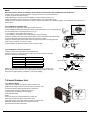
,QVWDOODWLRQ0DQXDO
Manifold Valve
$LU3XUJLQJDQG/HDNDJH7HVW
&RQQHFWFKDUJLQJKRVHRIPDQLIROGYDOYHWRFKDUJHHQGRIORZSUHVVXUH
YDOYHERWKKLJKORZSUHVVXUHYDOYHVPXVWEHWLJKWO\VKXW
&RQQHFWMRLQWRIFKDUJLQJKRVHWRYDFXXPSXPS
)XOO\RSHQWKHKDQGOHRI/RPDQLIROGYDOYH
2SHQWKHYDFXXPSXPSIRUYDFXXPL]DWLRQ$WWKHEHJLQQLQJVOLJKWO\
ORRVHQMRLQWQXWRIORZSUHVVXUHYDOYHWRFKHFNLIWKHUH
LVDLUFRPLQJLQVLGH,IQRLVHRIYDFXXPSXPSKDV
EHHQFKDQJHGWKHUHDGLQJRIPXOWLPHWHULV7KHQWLJKWHQWKHQXW
.HHSYDFXXPLQJIRUPRUHWKDQPLQVDQGPDNH
VXUHWKHUHDGLQJRIPXOWLPHWHULV;SDFP+J
)XOO\RSHQKLJKORZSUHVVXUHYDOYHV
5HPRYHFKDUJLQJKRVHIURPFKDUJLQJHQGRIORZSUHVVXUHYDOYH
7LJKWHQOLGRIORZSUHVVXUHYDOYH$VVKRZQLQ)LJ
Multimeter
-76cmHg
Manometer
Hi handle
Lo Handle
Charging hose
Low pressure valve
Fig.6
Vacuum pump
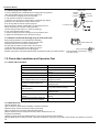
2XWGRRU&RQGHQVDWH'UDLQDJHRQO\IRUKHDWSXPSXQLW
'XULQJKHDWLQJRSHUDWLRQWKHFRQGHQVDWHDQGGHIURVWLQJ
ZDWHUVKRXOGEHGUDLQHGRXWUHOLDEO\WKURXJKWKHGUDLQKRVH
,QVWDOOWKHRXWGRRUGUDLQFRQQHFWRULQDĭKROHRQ
WKHEDVHSODWHDQGDWWDFKWKHGUDLQKRVHWRWKHFRQQHFWRU
VRWKDWWKHZDVWHZDWHUIRUPHGLQWKHRXWGRRUXQLWFDQEH
GUDLQHGRXW7KHKROHGLDPHWHUPXVWEHSOXJJHG
:KHWKHUWRSOXJRWKHUKROHVZLOOEHGHWHUPLQHGE\WKHGHDOHUVDFFRUGLQJWRDFWXDOFRQGLWLRQV
Drain-water hole
Bottom frame
Drain connecter
Hose (available commercially,
inner dia. 16mm)
&KHFNDIWHU,QVWDOODWLRQDQG2SHUDWLRQ7HVW
&KHFNDIWHU,QVWDOODWLRQ
,WHPVWREHFKHFNHG
3RVVLEOHPDOIXQFWLRQ
+DVLWEHHQ¿[HG¿UPO\"
7KHXQLWPD\GURSVKDNHRUHPLWQRLVH
+DYH\RXGRQHWKHUHIULJHUDQWOHDNDJH ,WPD\FDXVHLQVXI¿FLHQWFRROLQJKHDWLQJ
WHVW"
FDSDFLW\
,VKHDWLQVXODWLRQVXI¿FLHQW"
,WPD\FDXVHFRQGHQVDWLRQDQGGULSSLQJ
,VZDWHUGUDLQDJHVDWLVIDFWRU\"
,WPD\FDXVHFRQGHQVDWLRQDQGGULSSLQJ
,VWKHYROWDJHLQDFFRUGDQFHZLWKWKH
,WPD\FDXVHHOHFWULFPDOIXQFWLRQRU
UDWHGYROWDJHPDUNHGRQWKHQDPHSODWH" GDPDJHWKHSURGXFW
,VWKHHOHFWULFZLULQJDQGSLSLQJ
,WPD\FDXVHHOHFWULFPDOIXQFWLRQRU
FRQQHFWLRQLQVWDOOHGFRUUHFWO\DQG
GDPDJHWKHSDUW
VHFXUHO\"
+DVWKHXQLWEHHQFRQQHFWHGWRDVHFXUH
,WPD\FDXVHHOHFWULFDOOHDNDJH
HDUWKFRQQHFWLRQ"
,WPD\FDXVHHOHFWULFPDOIXQFWLRQRU
,VWKHSRZHUFRUGVSHFL¿HG"
GDPDJHWKHSDUW
$UHWKHLQOHWDQGRXWOHWRSHQLQJV
,WPD\FDXVHLQVXI¿FLHQWFRROLQJKHDWLQJ
EORFNHG"
FDSDFLW\
,VWKHOHQJWKRIFRQQHFWLRQSLSHVDQG
7KHUHIULJHUDQWFDSDFLW\LVQRWDFFXUDWH
UHIULJHUDQWFDSDFLW\EHHQUHFRUGHG"
2SHUDWLRQ7HVW
%HIRUH2SHUDWLRQ7HVW
'RQRWVZLWFKRQSRZHUEHIRUHLQVWDOODWLRQLV¿QLVKHGFRPSOHWHO\
(OHFWULFZLULQJPXVWEHFRQQHFWHGFRUUHFWO\DQGVHFXUHO\
&XWRIIYDOYHVRIWKHFRQQHFWLRQSLSHVVKRXOGEHRSHQHG
$OOWKHLPSXULWLHVVXFKDVVFUDSVDQGWKUXPVPXVWEHFOHDUHGIURPWKHXQLW
2SHUDWLRQ7HVW0HWKRG
6ZLWFKRQSRZHUDQGSUHVV212))EXWWRQRQWKHUHPRWHFRQWUROOHUWRVWDUWRSHUDWLRQ
3UHVV02'(EXWWRQWRVHOHFWWKH&22/+($71RWDYDLODEOHIRUFRROLQJRQO\XQLW)$1WRFKHFNZKHWKHUWKHRSHUDWLRQLVQRUPDORU
QRW
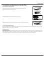
,QVWDOODWLRQ0DQXDO
,QVWDOODWLRQDQG0DLQWHQDQFHRI+HDOWK\)LOWHU
,QVWDOODWLRQRI+HDOWK\)LOWHU
/LIWXSWKHIURQWSDQHOIURPLWVWZRHQGVDVVKRZQE\WKHDUURZGLUHFWLRQDQG
WKHQUHPRYHWKHDLU¿OWHU$VVKRZQLQ¿JD
Fig.a
Fig.b
$WWDFKWKHKHDOWK\¿OWHURQWRWKHDLU¿OWHU$VVKRZQLQ¿JE
Air filter
Healthy filter
,QVWDOOWKHDLU¿OWHUSURSHUO\DORQJWKHDUURZGLUHFWLRQLQ)LJFDQGWKHQFORVHWKHSDQHO
Fig.c
&OHDQLQJDQG0DLQWHQDQFH
5HPRYHWKHKHDOWK\¿OWHUDQGUHLQVWDOOLWDIWHUFOHDQLQJDFFRUGLQJWRWKHLQVWDOODWLRQLQVWUXFWLRQ'RQWXVHEUXVKRUKDUGWKLQJVWRFOHDQ
WKH¿OWHU$IWHUFOHDQLQJEHVXUHWRGU\LWLQWKHVKDGH
6HUYLFH/LIH
7KHJHQHUDOVHULYHOLIHIRUWKHKHDOWK\¿OWHULVDERXWRQH\HDUXQGHUQRUPDOFRQGLWLRQ$VIRUVLOYHULRQ¿OWHULWLVLQYDOLGZKHQLWVVXUIDFH
EHFRPHVEODFNJUHHQ
Ɣ7KLVVXSSOHPHQWDU\LQVWUXFWLRQLVSURYLGHGIRUUHIHUHQFHWRWKHXQLWZLWKKHDOWK\¿OWHU,IWKHJUDSKLFVSURYLGHGKHUHLQLVGLIIHUHQWIURP
WKHDFWXDOSURGXFWSOHDVHUHIHUWRWKHDWXDOSURGXFW7KHTXDQWLW\RIKHDOWK\¿OWHUVLVEDVHGRQWKHDFWXDOGHOLYHU\
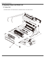
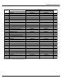
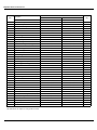
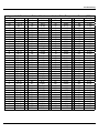
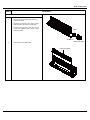
([SORGHG9LHZVDQG3DUWV/LVW
([SORGHG9LHZVDQG3DUWV/LVW
,QGRRU8QLW
*:+0%.'1$.,*:+0%.'1$.,*:+0%.'1$.,*:+0%.'1$.,
23
22
21
20
19
18
17
16
15
14
13
12
11
10
9
8
7
6
5
4
24
25
3
26
2
27
28
30
29
31
34
38
37
36
33
32
35
39
40
1
([SORGHG9LHZVDQG3DUWV/LVW
NO.
1
2
3
4
5
6
7
8
9
10
11
12
13
14
15
16
17
18
19
20
21
22
23
24
25
26
27
28
29
30
31
32
33
34
35
36
37
38
39
40
Description
Product Code
Front Panel
Display Board
Filter Sub-Assy
Electric Box Cover2
Screw Cover
Front Case Sub-Assy
Axile Bush
Guide Louver
Air Louver 1
Air Louver 2
Helicoid tongue
Left Axile Bush
Rear Case assy
Cross Flow Fan
O-Gasket sub-assy of Bearing
Ring of Bearing
Drainage hose
Wall Mounting Frame
Evaporator Assy
Evaporator Support
Cold Plasma Generator Sub-assy
Connecting Cable
Power Cord
Pipe Clamp
Fan Motor
Motor Press Plate
Rubber Plug (Water Tray)
Step Motor
Crank
Electric Box Assy
Electric Box
Terminal Board
Shield cover of Electric Box sub-assy
Electric Box Cover1
Capacitor CBB61
Jumper
Ambient Temperature Sensor
Main Board
Temperature Sensor
Remote Controller
The data above are subject to change without notice.
Part Code
GWH09MB-K3DNA3K/I
CB171N07600
20012548
30565007
1112220403
20122075
24252016
20012139
10542036
10512157
10512156
10512155
26112163
10512037
2220210301
10352017
76512051
26152022
0523001401
01252021
01002424
24212091
/
400205236
400204643
26112164
150120874
26112161
76712012
1521212901
10582070
20402397
2011208201
42011233
01592073
22242135
33010002
4202300102
390000451
30148783
390000591
305100413
GWH12MB-K3DNA3K/I
CB171N07700
20012548
30565007
1112220403
20122075
24252016
20012139
10542036
10512157
10512156
10512155
26112163
10512037
2220210301
10352017
76512051
26152022
0523001401
01252021
01002953
24212091
/
400205236
400204643
26112164
150120874
26112161
76712012
1521212901
10582070
20402396
2011208201
42011233
01592073
22242135
33010002
4202300104
390000451
30148783
390000591
305100413
Qty
1
1
2
1
1
1
1
1
1
1
1
1
1
1
1
1
1
1
1
1
/
0
1
1
1
1
1
1
1
1
1
1
1
1
1
1
1
1
1
1
([SORGHG9LHZVDQG3DUWV/LVW
NO.
1
2
3
4
5
6
7
8
9
10
11
12
13
14
15
16
17
18
19
20
21
22
23
24
25
26
27
28
29
30
31
32
33
34
35
36
37
38
39
40
Description
Product Code
Front Panel
Display Board
Filter Sub-Assy
Electric Box Cover2
Screw Cover
Front Case Sub-Assy
Axile Bush
Guide Louver
Air Louver 1
Air Louver 2
Helicoid tongue
Left Axile Bush
Rear Case assy
Cross Flow Fan
O-Gasket sub-assy of Bearing
Ring of Bearing
Drainage hose
Wall Mounting Frame
Evaporator Assy
Evaporator Support
Cold Plasma Generator Sub-assy
Connecting Cable
Power Cord
Pipe Clamp
Fan Motor
Motor Press Plate
Rubber Plug (Water Tray)
Step Motor
Crank
Electric Box Assy
Electric Box
Terminal Board
Shield cover of Electric Box sub-assy
Electric Box Cover1
Capacitor CBB61
Jumper
Ambient Temperature Sensor
Main Board
Temperature Sensor
Remote Controller
Part Code
GWH09MB-K3DNA2K/I
CB181N05700
20022148
30565054
1112220403
20122075
24252016
20012139
10542036
10512157
10512156
10512155
26112163
10512037
2220210301
10352017
76512051
26152022
0523001401
01252021
01002424
24212091
/
400205235
4002046410
26112164
150120874
26112161
76712012
1521212901
10582070
20402761
2011208201
42011233
01592073
22242135
33010002
4202300102
390000451
30148783
390000591
305100413
GWH12MB-K3DNA2K/I
CB181N05800
20022148
30565054
1112220403
20122075
24252016
20012139
10542036
10512157
10512156
10512155
26112163
10512037
2220210301
10352017
76512051
26152022
0523001401
01252021
01002953
24212091
/
400205235
4002046410
26112164
150120874
26112161
76712012
1521212901
10582070
20402761
2011208201
42011233
01592073
22242135
33010002
4202300104
390000451
30148783
390000591
305100413
Qty
1
1
2
1
1
1
1
1
1
1
1
1
1
1
1
1
1
1
1
1
/
0
1
1
1
1
1
1
1
1
1
1
1
1
1
1
1
1
1
1
The data above are subject to change without notice.
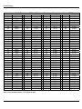
([SORGHG9LHZVDQG3DUWV/LVW
*:+0%.'1&.,*:+0%.'1&.,
36
37
39
38
13
14
12
11
15
10
16
9
8
6
7
17
5
4
18
3
2
20
1
21
24
23
22
25
27
26
28
29
35
30
34
31
33
32
19
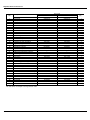
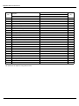
([SORGHG9LHZVDQG3DUWV/LVW
12
'HVFULSWLRQ
3URGXFW&RGH
)URQW3DQHO6XE$VV\
)LOWHU6XE$VV\
3DUW&RGH
*:+0%.'1&.,
*:+0%.'1&.,
&%1
&%1
4W\
)URQW&DVH6XEDVV\
*XLGH/RXYHU
$[LOH%XVK
$LU/RXYHU
+HOLFRLG7RQJXH
/HIW$[LOH%XVK
5HDU&DVHDVV\
5LQJRI%HDULQJ
2*DVNHWVXEDVV\RI%HDULQJ
&URVV)ORZ)DQ
(YDSRUDWRU6XSSRUW
(YDSRUDWRU$VV\
0RWRU3UHVV3ODWH
:DOO0RXQWLQJ)UDPH
'UDLQDJH+RVH
)DQ0RWRU
&RQQHFWLQJSLSHFODPS
5XEEHU3OXJ:DWHU7UD\
6WHSSLQJ0RWRU
&UDQN
6FUHZ&RYHU
$LU/RXYHU
(OHFWULF%R[
0DJQHWLF5LQJ
7HUPLQDO%RDUG
(OHFWULF%R[&RYHU
0DLQ%RDUG
&DSDFLWRU&%%
-XPSHU
:LUH&ODPS
6KLHOG&RYHURI(OHFWULF%R[6XEDVV\
/RZHU6KLHOG6XEDVV\RI(OHFWULF%R[
(OHFWULF%R[$VV\
3RZHU&RUG
&RQQHFWLQJ&DEOH
'LVSOD\%RDUG
5HPRWH&RQWUROOHU
7KHGDWDDERYHDUHVXEMHFWWRFKDQJHZLWKRXWQRWLFH
([SORGHG9LHZVDQG3DUWV/LVW
*:+0%.'1(.,*:+0%.'1(.,
36
37
39
38
13
14
12
11
15
10
16
9
8
6
7
17
5
4
18
3
2
20
1
21
24
23
22
25
27
26
28
29
35
30
34
31
33
32
19
([SORGHG9LHZVDQG3DUWV/LVW
12
'HVFULSWLRQ
3URGXFW&RGH
3DUW&RGH
*:+0%.'1(.,
*:+0%.'1(.,
&%1
&%1
4W\
)URQW3DQHO$VV\
)LOWHU6XE$VV\
)URQW&DVH6XEDVV\
*XLGH/RXYHU
$[LOH%XVK
$LU/RXYHU
+HOLFRLG7RQJXH
/HIW$[LOH%XVK
5HDU&DVHDVV\
5LQJRI%HDULQJ
2*DVNHWVXEDVV\RI%HDULQJ
&URVV)ORZ)DQ
(YDSRUDWRU6XSSRUW
(YDSRUDWRU$VV\
0RWRU3UHVV3ODWH
:DOO0RXQWLQJ)UDPH
'UDLQDJH+RVH
)DQ0RWRU
&RQQHFWLQJSLSHFODPS
5XEEHU3OXJ:DWHU7UD\
6WHSSLQJ0RWRU
&UDQN
6FUHZ&RYHU
$LU/RXYHU
(OHFWULF%R[
0DJQHWLF5LQJ
7HUPLQDO%RDUG
(OHFWULF%R[&RYHU
0DLQ%RDUG
&DSDFLWRU&%%
-XPSHU
:LUH&ODPS
6KLHOG&RYHURI(OHFWULF%R[6XEDVV\
/RZHU6KLHOG6XEDVV\RI(OHFWULF%R[
(OHFWULF%R[$VV\
3RZHU&RUG
&RQQHFWLQJ&DEOH
'LVSOD\%RDUG
5HPRWH&RQWUROOHU
7KHGDWDDERYHDUHVXEMHFWWRFKDQJHZLWKRXWQRWLFH
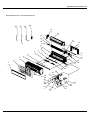
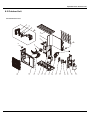
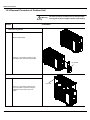
([SORGHG9LHZVDQG3DUWV/LVW
2XWGRRU8QLW
*:+0%.'1$.2
18
19
20
21
22
23
24
17
26
25
16
15
1
2
3
4
5
6
7
8
9
10
11
12
13
14
([SORGHG9LHZVDQG3DUWV/LVW
12
'HVFULSWLRQ
3URGXFW&RGH
3DUW&RGH
*:+0%.'1$.2
4W\
&%:
)URQW*ULOO
&DELQHW6XEDVV\
$[LDO)ORZ)DQ
&KDVVLV6XEDVV\
&RPSUHVVRUDQG)LWWLQJV
:D\9DOYH$VV\
3
&ODSERDUG6XE$VV\
'UDLQDJH&RQQHFWHU
9DOYH6XSSRUW
&XWRII9DOYH$VV\
*
3
9DOYH
9DOYH6XSSRUW%ORFN
5LJKW6LGH3ODWH6XE$VV\
%LJ+DQGOH
0DJQHW&RLO
0DJQHW&RLO
5HDU*ULOO
(OHFWULF%R[
)LOWHU%RDUG
0DLQ%RDUG
(OHFWULF%R[$VV\
7RS&RYHU6XE$VV\
&RQGHQVHU$VV\
0RWRU6XSSRUW
)DQ0RWRU
6PDOO+DQGOH
7KHGDWDDERYHDUHVXEMHFWWRFKDQJHZLWKRXWQRWLFH
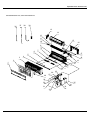
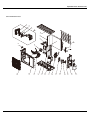
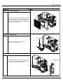
([SORGHG9LHZVDQG3DUWV/LVW
*:+0%.'1$.2
18
19
20
21
22
23
24
17
26
25
16
15
1
2
3
4
5
6
7
8
9
10
11
12
13
14
([SORGHG9LHZVDQG3DUWV/LVW
12
'HVFULSWLRQ
3URGXFW&RGH
3DUW&RGH
*:+0%.'1$.2
4W\
&%:
)URQW*ULOO
&DELQHW6XEDVV\
$[LDO)ORZ)DQ
3
&KDVVLV6XEDVV\
&ODSERDUG6XE$VV\
'UDLQDJH&RQQHFWHU
&RPSUHVVRUDQG)LWWLQJV
:D\9DOYH$VV\
9DOYH6XSSRUW
9DOYH6XSSRUW%ORFN
5LJKW6LGH3ODWH6XE$VV\
0DJQHW&RLO
5HDU*ULOO
*
3
&XWRII9DOYH$VV\
9DOYH
%LJ+DQGOH
(OHFWULF([SDQVLRQ9DOYH6XE$VV\
(OHFWULF%R[
)LOWHU%RDUG
0DLQ%RDUG
(OHFWULF%R[$VV\
7RS&RYHU6XE$VV\
&RQGHQVHU$VV\
0RWRU6XSSRUW
)DQ0RWRU
6PDOO+DQGOH
7KHGDWDDERYHDUHVXEMHFWWRFKDQJHZLWKRXWQRWLFH
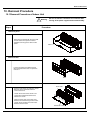
7URXEOHVKRRWLQJ
7URXEOHVKRRWLQJ
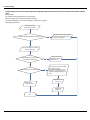
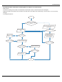
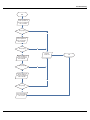
0DOIXQFWLRQ$QDO\VLV
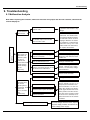
1RWH:KHQUHSODFLQJWKHFRQWUROOHUPDNHVXUHLQVHUWWKHZLUHMXPSHULQWRWKHQHZFRQWUROOHURWKHUZLVHWKH
XQLWZLOOGLVSOD\&
The breaker trips at once when it
is set to “ON”.
Air conditioner can not
start up
Trip of breaker or
blow of fuse
The air conditioner does not
react after it is
powered ( after
the plug is
inserted, the
buzzer does not
sound and the
remote startup
has no
response)
The breaker trips in few minutes
when it is set to “ON”.
No power
Check power supply circuit.
Power plug is not well plugged in
and poor connection.
Check if the plug is properly
plugged in and make the loose
contact firm.
Fuse of controller burnt out
Change controller fuse
The transformer connection is
loose or has bad contact or the
transformer has malfunction.
Fasten the wiring; measure the
output voltage of the transformer , if it is incorrect, change
the transformer.
Controller is broken
Check remote controller
Remote controller malfunction
Receiver loose or poor connection
Receiver is broken
Power voltage is too low
to ground to see if there is any
leakage.
The circuit or the part of the air
conditioner has malfunction.
They heat and break the insulation and lead to short circuit or
creepage. Measure the insulation resistance or eliminate the
malfunction one by one. If the
breaker itself has malfunction,
then replace the breaker.
Remote controller is short of power
The remote
controller does
not receive
signals (after it
is powered, the
buzzer will
sound, unless it
has
malfunction)
Measure insulation resistance
Change batteries
First, press the manual switch
button AUTO,if there is no
response,check based on the
above methods. If it runs normally after pressing the button,
check again whether the installation position and the connection wire of the reception head
is correct. If it is correct,then replace the receiver or the remote
controller.
Check the voltage. If it is lower than 10% of
the rated voltage, check the cause, improve
the power supply condition and add the stabilized voltage power supply.
7URXEOHVKRRWLQJ
Improper set of temperature
Adjust set temperature
If cooling (heating) load is
Check the forecasted load of cooling (heating)
proper
The refrigerant has leakage or is
insufficient
Check and fill the leakage, then
vacuumize it and supplement the refrigerant as required
Leakage between the high presMalfunction of
refrigerant
flow
sure and the low pressure inside the compressor
Malfunction of four-way valve
Local block of capillary
Poor COOL(HEAT) operation
Replace the compressor
Blockage of cooling system
Replace the four-way valve
Replace the capillary
Judge whether the system is blocked by
observing the condensation of evaporator and the pressure value of the high
pressure manometer and take measures
to deal with the system.
Heat insulation for the connection
pipes of the indoor unit and the outdoor unit is bad.
Make sure that heat insulation for the thick and thin pipes
is good. Heat insulation must also be provided for the
joint andthe exposed part of the copper pipe .
Block of outdoor heat exchanger
Clean the dust accumulated on the
surface of the heat exchanger.
Air filter were blocked
Clean the filter
Fan speed was set too slow
Air circulation
is insufficient
Fan rotation speed becomes
low
The installation position of the
outdoor unit is not appropriate.
The outdoor temperature is too high.
To set the fan speed to high or
middle speed
Capacitor
Replace the
damage
capacitor
Motor damage
Replace the motor
Good ventilation must be provided for the
installation position of the outdoor unit.
Properly install the rainproof plate or the sunproof plate. If the
maximum cool air still can not meet the requirement, it is suggested to replace the air conditioner.
The air tightness is not enough. People
come in and out too frequently. There
are heating devices indoors.
Keep certain air tightness indoors, try not to use
electricalappliance with large quantity of heat
7URXEOHVKRRWLQJ
The indoor fan motor is burned or
breaks or has the heat protector
malfunction.
Replace the fan motor or the defective part.
The fan does not
The built-in heat protector of the
motor breaks frequently because the
Replace the fan motor
run when it is set
to supply air.
motor is abnormal.
Wrong connection
The fan capacitor has open circuit or
is damaged.
Make the correction connection based on
the circuit drawing.
Replace the fan capacitor of the same type
and same specification.
In the cooling and
The outdoor fan motor is damaged.
Replace the fan motor
heating mode,
the compressor
Wrong connection
Make the correct connection based on the
circuit drawing
The outdoor fan capacitor is damaged.
Replace the fan capacitor
runs, but the outdoor fan does not
run.
Malfunction of compressor
Replace the compressor
Breakage of running capacitor of
In the cooling
and heating
mode, the
outdoor fan
runs, but the
compressor
does not run.
compressor
The voltage is too low or too
high.
Wrong wire connection
The protector itself has malfunction.
The refrigerant is not enough or is too
much.
The compressor is too hot
and leads to the
action of the
protector.
Manostat is recommended.
Connect the circuit diagram correctly
Use the multimeter to check whether the
contact of the compressor is on when it is
not overheated. If it is not on, then replace
the protector
Adjust the volume of the refrigerant
The capillary is blocked and the temperature rises.
Replace the capillary
The compressor does not run
Replace the compressor
smoothly or is stuck. The air discharge
valve is damaged
The protector itself has malfunction.
Replace the capacitor
Replace the protector
7URXEOHVKRRWLQJ
The torque of the swing motor is not
enough
The swing fan
does not run.
Wrong connection
First, check whether the connection is
wrong. If no, replace the parts
The controller is damaged(IC2003 is
damaged, the swing relay can not
close, etc)
Controller malfunction (IC2003
broken, creepage of parallel capaci-
Change controller
In cool, heat
mode, the
tor of relay loop, relay is broken etc.)
outdoor unit
and compres-
Wire loose or wrong connection
Correctly wire according to the drawing
Improper setting of temperature
Adjust setting temp.
Drainage pipe blocked or broken
Change drainage pipe
Wrap of refrigerant pipe joint is not
Re-wrap and make it tight.
sor will not run.
Water leakage
close enough.
Fan of indoor unit contacts other parts
Foreign object in indoor unit
Compressor shakes too much
Adjust fan location
Take out the foreign object
Adjust support washer of compressor, and
tighten loosen screws
Abnormal sound
and shake
Touch of pipeline of outdoor unit
Separate the touching pipeline.
Touch of inner plates
1. Tighten connect screw.
2. Stick absorbing clay between plates.
Louver of outdoor unit touched outer
case.
Adjust location of louver.
Abnormal sound inside compressor
Change compressor
7URXEOHVKRRWLQJ
)ODVKLQJ/('RI,QGRRU2XWGRRU8QLWDQG3ULPDU\-XGJHPHQW
)ODVKLQJ/('RI,QGRRU2XWGRRU8QLWDQG3ULPDU\-XGJHPHQW
Display Method of Indoor Unit
NO.
1
2
3
High
pressure
protection of
system
Antifreezing
protection
In defect of
refrigerant
4
High
discharge
temperature
protection of
compressor
5
Overcurrent
protection
6
Communication
Malfunction
7
High
temperature
resistant
protection
8
EEPROM
malfunction
9
Limit/
decrease
frequency
due to high
temperature
of module
10
Malfunction
Name
Malfunction
protection of
jumper cap
Indicator Display (during
Dual-8 blinking, ON 0.5s and OFF
Code 0.5s)
Display
Operation Cool
Heating
Indicator Indicator Indicator
E1
E2
Display Method of Outdoor
Unit
Indicator has 3 kinds of
display status and during
blinking, ON 0.5s and OFF
0.5s
A/C status
Yellow
Red
Green
Indicator Indicator Indicator
During cooling and drying
operation, except indoor
fan operates, all loads stop
operation.
During heating operation, the
complete unit stops.
OFF 3s
and blink
once
OFF 3S
and blink
twice
Possible Causes
During cooling and drying
operation, compressor and
outdoor fan stop while indoor
fan operates.
OFF 1S
and blink
3 times
OFF 1S
and
blink
9 times
F0
Possible reasons:
1. Refrigerant was superabundant;
2. Poor heat exchange (including
and bad radiating environment );
Ambient temperature is too high.
1. Poor air-return in indoor unit;
2. Fan speed is abnormal;
3. Evaporator is dirty.
1.In defect of refrigerant;
The Dual-8 Code Display will 2.Indoor evaporator temperature
show F0 and the complete unit sensor works abnormally;
stops.
3.The unit has been plugged up
somewhere.
E4
OFF 3S
and blink
4 times
OFF 1S
and blink
7 times
During cooling and drying
operation, compressor and
outdoor fan stop while indoor
fan operates. During heating
operation, all loads stop.
Please refer to the malfunction
analysis (discharge protection,
overload).
E5
OFF 3S
and blink
5
times
OFF 1S
and blink
5 times
During cooling and drying
operation, compressor and
outdoor fan stop while indoor
fan operates. During heating
operation, all loads stop.
1. Supply voltage is unstable;
2. Supply voltage is too low and
load is too high;
3. Evaporator is dirty.
E6
OFF 3S
and blink
6
times
Always
ON
During cooling operation,
compressor stops while
indoor fan motor operates.
During heating operation, the
complete unit stops.
Refer to the corresponding
malfunction analysis.
E8
OFF 3S
and blink
8
times
OFF 1S
and blink
6 times
During cooling operation:
compressor will stop while
indoor fan will operate.
During heating operation, the
complete unit stops.
Refer to the malfunction analysis
(overload, high temperature
resistant).
OFF 3S OFF 1S
and blink and blink
15 times 11 times
EE
OFF 3S OFF 3S
and blink and blink
6 times 6 times
EU
C5
OFF 3S
and blink
15 times
During cooling and drying
operation, compressor will stop
Replace outdoor control panel AP1
while indoor fan will operate;
During heating operation, the
complete unit will stop
All loads operate normally,
while
operation frequency for
compressor is decreased
Wireless remote receiver and
button are effective, but can
not dispose the related
command
Discharging after the complete unit
is de-energized for 20mins, check
whether the thermal grease on
IPM Module of outdoor control
the radiator is inserted tightly.
If its no use, please replace control
panel AP1.
1. No jumper cap insert on
mainboard.
2. Incorrect insert of jumper cap.
3. Jumper cap damaged.
4. Abnormal detecting circuit of
mainboard.
7URXEOHVKRRWLQJ
Display Method of Indoor Unit
NO.
11
12
13
14
15
Malfunction
Name
Gathering
refrigerant
Indoor
ambient
temperature
sensor is
open/short
circuited
Indoor
evaporator
temperature
sensor is
open/short
circuited
Outdoor
ambient
temperature
sensor is
open/short
circuited
Outdoor
condenser
temperature
sensor is
open/short
circuited
16
Outdoor
discharge
temperature
sensor is
open/short
circuited
17
Limit/
decrease
frequency
due to
overload
18
Decrease
frequency
due to
overcurrent
Indicator Display (during
Dual-8 blinking, ON 0.5s and OFF
Code 0.5s)
Display
Operation Cool
Heating
Indicator Indicator Indicator
Fo
F1
OFF 3S OFF 3S
and blink and blink
1 times 1 times
Display Method of Outdoor
Unit
Indicator has 3 kinds of
display status and during
blinking, ON 0.5s and OFF
0.5s
A/C status
Yellow
Red
Green
Indicator Indicator Indicator
When the outdoor unit receive
signal of Gathering refrigerant
,the system will be forced to
Nominal cooling mode
run under cooling mode for
gathering refrigerant
OFF 1S
and blink
17 times
1. Loosening or bad contact of
indoor ambient temp. sensor and
During cooling and drying
mainboard terminal.
operation, indoor unit operates
2. Components in mainboard fell
while other loads will stop;
down leads short circuit.
during heating operation,
3. Indoor ambient temp. sensor
the complete unit will stop
damaged.(check with sensor
operation.
resistance value chart)
4. Mainboard damaged.
OFF 3S
and blink
once
AC stops operation once
reaches the setting
F2
OFF 3S
and blink
twice
F3
OFF 3S
and blink
3 times
F4
OFF 3S
and blink
4 times
Possible Causes
temperature. Cooling, drying:
internal fan motor stops
operation while other loads
stop operation; heating: AC
stop operation
OFF 1S
and
blink
6 times
OFF 1S
and
blink
5 times
During cooling and drying
operating, compressor stops
while indoor fan operates;
During heating operation,
the complete unit will stop
operation
During cooling and drying
operation, compressor stops
while indoor fan will operate;
During heating operation,
the complete unit will stop
operation.
1. Loosening or bad contact of
Indoor
evaporator temp. sensor and
mainboard terminal.
2. Components on the mainboard
fall
down leads short circuit.
3. Indoor evaporator temp. sensor
damaged.(check temp. sensor
value
chart for testing)
4. Mainboard damaged.
Outdoor temperature sensor
hasnt been connected well or
is damaged. Please check it by
referring to the resistance table for
temperature sensor)
Outdoor temperature sensor
hasnt been connected well or
is damaged. Please check it by
referring to the resistance table for
temperature sensor)
F5
OFF 3S
and blink
5 times
OFF 1S
and
blink
7 times
During cooling and drying
operation, compressor will sop
after operating for about 3
mins,
while indoor fan will operate;
During heating operation, the
complete unit will stop after
operating for about 3 mins.
1.Outdoor temperature sensor
hasnt been connected well or is
damaged. Please check it by
referring to the resistance table for
temperature sensor)
2.The head of temperature sensor
hasnt been inserted into the copper
tube
F6
OFF 3S
and blink
for 6
times
OFF 1S
and
blink
3 times
All loads operate normally,
while
operation frequency for
compressor is decreased
Refer to the malfunction analysis
(overload, high temperature
resistant)
F8
OFF 3S
and blink
8 times
OFF 1S
and
blink
once
All loads operate normally,
while
operation frequency for
compressor is decreased
The input supply voltage is too low;
System pressure is too high and
overload
7URXEOHVKRRWLQJ
Display Method of Indoor Unit
NO.
Malfunction
Name
Indicator Display (during
Dual-8 blinking, ON 0.5s and OFF
Code 0.5s)
Display
Operation Cool
Heating
Indicator Indicator Indicator
Display Method of Outdoor
Unit
Indicator has 3 kinds of
display status and during
blinking, ON 0.5s and OFF
0.5s
19
F9
OFF 3S
and blink
9 times
OFF 1S
and
blink
twice
All loads operate normally,
while
OFF 3S OFF 3S
and blink and blink
2 times 2 times
OFF 1S
and
blink
4 times
All loads operate normally,
discharge
20
Limit/
decrease
frequency
FH
due to
antifreezing
21
Voltage for
DC bus-bar
is too high
PH
OFF 1S
and
blink
13 times
OFF 3S
and blink
11 times
Possible Causes
Yellow
Red
Green
Indicator Indicator Indicator
Decrease
frequency
due to
high air
A/C status
operation frequency for
compressor is decreased
while operation frequency for
compressor is decreased
Overload or temperature is too
high;
Malfunction of electric expansion
valve (EKV)
Poor air-return in indoor unit or fan
speed is too low
1. Measure the voltage of position
L and N on wiring board (XT), if the
During cooling and drying
voltage is higher than 265VAC, turn
operation, compressor will stop on the unit after the supply voltage
is increased to the normal range.
while indoor fan will operate;
2.If the AC input is normal,
During heating operation, the measure the voltage of electrolytic
complete unit will stop
capacitor C on control panel (AP1),
operation.
if its normal, theres malfunction
for the circuit, please replace the
control panel (AP1)
1. Measure the voltage of position
L and N on wiring board (XT), if the
voltage is higher than 150VAC,
22
Voltage of
DC bus-bar
is too low
OFF 3S
and blink
21 times
PL
OFF 1S
and
blink
12 times
During cooling and drying
operation, compressor will stop
while indoor fan will operate;
During heating operation, the
complete unit will stop
turn on the unit after the supply
voltage is increased to the normal
range.
2.If the AC input is normal,
measure the voltage of electrolytic
capacitor C on control panel (AP1),
if its normal, theres malfunction
for the circuit, please replace the
control panel (AP1)
23
Compressor
Min
frequence in
test state
24
Compressor
rated
frequence in
test state
25
Compressor
maximum
frequence in
test state
P0
(during
blinking,
ON
0.25s
and OFF
0.25s)
(during
blinking,
ON
0.25s
and OFF
0.25s)
Showing during min. cooling or
min. heating test
P1
(during
blinking,
ON
0.25s
and OFF
0.25s)
(during
blinking,
ON
0.25s
and OFF
0.25s)
Showing during nominal cooling or
nominal heating test
P2
(during
blinking,
ON
0.25s
and OFF
0.25s)
(during
blinking,
ON
0.25s
and OFF
0.25s)
Showing during max. cooling or
max. heating test
7URXEOHVKRRWLQJ
Display Method of Indoor Unit
NO.
Malfunction
Name
Indicator Display (during
Dual-8 blinking, ON 0.5s and OFF
Code 0.5s)
Display
Operation Cool
Heating
Indicator Indicator Indicator
Compressor
26
intermediate
frequence in
test state
P3
(during
blinking,
ON
0.25s
and OFF
0.25s)
Display Method of Outdoor
Unit
Indicator has 3 kinds of
display status and during
blinking, ON 0.5s and OFF
protection of
phase
current for
P5
(during
blinking,
ON
0.25s
and OFF
0.25s)
28
29
30
Malfunction
of module
temperature
sensor circuit
Module high
temperature
protection
PU
P7
P8
Showing during middle cooling or
middle heating test
During cooling and drying
Refer to the malfunction
operation, compressor will stop
analysis (IPM protection, loss
while indoor fan will operate;
of synchronism protection and
During heating operation, the
overcurrent protection of phase
complete unit will stop
current for compressor.
operation.
OFF 3S
and blink
15 times
compressor
Charging
malfunction
of capacitor
Possible Causes
Yellow
Red
Green
Indicator Indicator Indicator
Overcurrent
27
A/C status
0.5s
OFF 3S
and blink
17 times
OFF 3S
and blink
18 times
OFF 3S
and blink
19 times
During cooling and drying
operation, compressor will stop
Refer to the part three—charging
while indoor fan will operate;
malfunction analysis of capacitor
During heating operation, the
complete unit will stop
During cooling and drying
operation, compressor will stop
while indoor fan will operate;
Replace outdoor control panel AP1
During heating operation, the
complete unit will stop
During cooling operation,
compressor will stop while
indoor fan will operate;
During heating operation, the
complete unit will stop
After the complete unit is deenergized for 20mins, check
whether the thermal grease on IPM
Module of outdoor control panel
radiator is inserted tightly. If its no
use, please replace control panel
AP1.
Decrease
frequency
31
due to high
temperature
resistant
H0
10 times
during
heating
operation
32
Static
dedusting
H2
protection
33
Overload
protection for
compressor
OFF 3S
and blink
All loads operate normally,
while
operation frequency for
compressor is decreased
Refer to the malfunction analysis
(overload, high temperature
During cooling and drying
operation, compressor will stop
while indoor fan will operate;
During heating operation, the
complete unit will stop
operation.
1. Wiring terminal OVC-COMP
is loosened. In normal state, the
resistance for this terminal should
be less than 1ohm.
2.Refer to the malfunction analysis (
discharge protection, overload)
resistant)
OFF 3S
and blink
twice
H3
OFF 3S OFF 1S
and blink and blink
3 times 8 times
7URXEOHVKRRWLQJ
Display Method of Indoor Unit
NO.
Malfunction
Name
Indicator Display (during
Dual-8 blinking, ON 0.5s and OFF
Code 0.5s)
Display
34
System is
abnormal
display status and during
blinking, ON 0.5s and OFF
0.5s
H5
OFF 3S OFF 1S
and blink and blink
5 times 4 times
36
Module
temperature
is too high
H5
OFF 3S OFF 1S
and blink and blink
5 times 10 times
37
Internal motor
(fan motor) do
not operate
H6
38
Desynchronizing of
compressor
H7
OFF 3S
and blink
7 times
39
PFC
protection
HC
OFF 3S OFF 1S
and blink and blink
6 times 14 times
while indoor fan will operate;
During heating operation, the
complete unit will stop
Refer to the malfunction analysis
(overload, high temperature
resistant)
operation.
During cooling and drying
Refer to the malfunction
operation, compressor will stop
analysis (IPM protection, loss
while indoor fan will operate;
of synchronism protection and
During heating operation, the
overcurrent protection of phase
complete unit will stop
current for compressor.
operation.
1. Bad contact of DC motor
feedback terminal.
Internal fan motor, external fan 2. Bad contact of DC motor
motor, compressor and electric control end.
heater stop operation,guide
3. Fan motor is stalling.
louver stops at present
4. Motor malfunction.
location.
5. Malfunction of mainboard rev
detecting circuit.
During cooling and drying
Refer to the malfunction
operation, compressor will stop analysis (IPM protection, loss
while indoor fan will operate;
of synchronism protection and
During heating operation, the
overcurrent protection of phase
complete unit will stop
current for compressor.
operation.
During cooling and drying
operation, compressor will stop
while indoor fan will operate;
Refer to the malfunction analysis
During heating operation, the
complete unit will stop
operation.
OFF 3S
and blink
11 times
OFF 1S
and
blink
14 times
DC fan motor malfunction or
Outdoor DC fan motor
malfunction lead to compressor system blocked or the connector
stop operation,
loosed
OFF 3S
and blink
23 times
OFF 1S
and blink
9 times
compressor stop operation and
To protect the electronical
Outdoor fan motor will stop
components when detect high
30s latter , 3 minutes latter
fan motor and compressor will power
restart
OFF 1S
and blink
16 times
compressor and Outdoor fan
motor can’t work
41
power
protection
L9
OFF 3S
and blink
20 times
42
Indoor unit
and outdoor
unit doesn't
match
LP
OFF 3S
and blink
19 times
Failure startup
Possible Causes
L3
malfunction
43
During cooling and drying
operation, compressor will stop
OFF 3S OFF 1S
and blink and blink
4 times 6 times
H4
IPM
protection
Outdoor DC
fan motor
A/C status
Operation Cool
Heating Yellow
Red
Green
Indicator Indicator Indicator Indicator Indicator Indicator
35
40
Display Method of Outdoor
Unit
Indicator has 3 kinds of
LC
OFF 3S
and blink
11 times
Indoor unit and outdoor unit doesn't
match
During cooling and drying
operation, compressor will stop
while indoor fan will operate;
Refer to the malfunction analysis
During heating operation, the
complete unit will stop
operation.
7URXEOHVKRRWLQJ
Display Method of Indoor Unit
NO.
Malfunction
Name
Indicator Display (during
Dual-8 blinking, ON 0.5s and OFF
Code 0.5s)
Display
Operation Cool
Heating
Indicator Indicator Indicator
Malfunction of
phase current
44
detection
circuit for
U1
Display Method of Outdoor
Unit
Indicator has 3 kinds of
display status and during
blinking, ON 0.5s and OFF
45
46
47
48
dropping for
DC bus-bar
Malfunction
of complete
units current
detection
The four-way
valve is
abnormal
Zerocrossing
malfunction of
outdoor unit
Possible Causes
Yellow
Red
Green
Indicator Indicator Indicator
OFF 3S
During cooling and drying
operation, compressor will stop
and blink
13 times
while indoor fan will operate;
During heating operation, the
compressor
Malfunction of
voltage
A/C status
0.5s
Replace outdoor control panel AP1
complete unit will stop
OFF 3S
and blink
20 times
U3
U5
U7
U9
During cooling and drying
operation, compressor will stop
while indoor fan will operate;
During heating operation, the
complete unit will stop
Supply voltage is unstable
OFF 3S
and blink
13 times
During cooling and drying
operation, the compressor will
Theres circuit malfunction on
stop while indoor fan will
outdoor units control panel AP1,
operate;
please replace the outdoor units
During heating operating,
control panel AP1.
the complete unit will stop
operation.
OFF 3S
and blink
20 times
If this malfunction occurs
during
heating operation, the complete
unit will stop operation.
1.Supply voltage is lower than
AC175V;
2.Wiring terminal 4V is loosened or
broken;
3.4V is damaged, please replace
4V.
During cooling operation,
compressor will stop while
indoor fan will operate; during
heating,the complete unit will
stop operation.
Replace outdoor control panel AP1
OFF 3S
and blink
18 times
Frequency
OFF 1S
and blink
13 times
49
limiting
(power)
50
Compressor
running
51
The
temperature
for turning
on the unit is
reached
OFF 1S
and blink
8 times
52
Frequency
limiting
(module
temperature)
OFF 1S
and blink
11 times
OFF 1S
and blink
once
7URXEOHVKRRWLQJ
Display Method of Indoor Unit
Indicator Display (during
NO.
Malfunction
Name
status and during blinking, ON
Dual-8 blinking, ON 0.5s and OFF
0.5s)
0.5s and OFF 0.5s
Code
Heating Yellow
Red
Green
Display Operation Cool
Indicator
53
Display Method of Outdoor Unit
Indicator has 3 kinds of display
Indicator Indicator Indicator Indicator
Defrosting
Possible Causes
Indicator
OFF 0.5S
and blink
once
Normal
communication
54
A/C status
OFF 3S
and blink
once
(during
OFF 1S
blinking,
and blink
ON 10s
twice
and OFF
0.5s)
Defrosting will occur in
heating
mode. Compressor will
operate
while indoor fan will stop
operation.
Its the normal state
7URXEOHVKRRWLQJ
+RZWR&KHFN6LPSO\WKH0DLQ3DUW
&DSDFLWRUFKDUJHIDXOW)DXOWZLWKRXWGRRUXQLW$3EHORZUHIHUVWRWKHRXWGRRUFRQWUROSDQHO
0DLQ&KHFN3RLQWV
Ɣ8VH$&YROWPHWHUWRFKHFNLIWKHYROWDJHEHWZHHQWHUPLQDO/DQG1RQWKHZLULQJERDUGLVZLWKLQ9$&a9$&
Ɣ,VWKHUHDFWRU/FRUUHFWO\FRQQHFWHG",VWKHFRQQHFWLRQORRVHRUIDOOHQ",VWKHUHDFWRU/GDPDJHG"
)DXOWGLDJQRVLVSURFHVV
Turn on the unit
and wait 1 minute
Use DC voltmeter
to measure the
voltage on the two
ends of electrolytic
capacitor
Voltage higher than 200V?
Y
Fault with the voltage
testing circuit on
control panel AP1
Replace the control
panel AP1
N
Measure the AC voltage between
terminalL and N on wiring board
XT(power supply)
Voltage within
210VAC~250VAC?
N
Shut down the power
and repair the power
supply to restore the
range
210VAC~250VAC
power on and
restart the unit
If the fault is
eliminated?
Y
Y
Shut down the power and wait 20 minutes;
or use DC voltmeter to measure the voltage
on the two ends of capacitor , until the
voltage is lower than 20V
N
Check the
connection of reactor
(L in the Electrical
Wiring Diagram)
If the wiring of
reactor Lis normal?
N
Connect the reactor
Laccording to Electrical Wiring Diagram correctly
Re-energize and
turn on the unit
If the fault is
eliminated?
Y
Y
Replace the control
panel AP1
N
End
7URXEOHVKRRWLQJ
,30 3URWHFWLRQ 2XWRIVWHS )DXOW &RPSUHVVRU 3KDVH 2YHUFXUUHQW $3 EHORZ UHIHUV WR WKH RXWGRRU FRQWURO
SDQHO
0DLQFKHFNSRLQWV
Ɣ,VWKHFRQQHFWLRQEHWZHHQFRQWUROSDQHO$3DQGFRPSUHVVRU&203VHFXUH"/RRVH",VWKHFRQQHFWLRQLQFRUUHFWRUGHU"
Ɣ,VWKHYROWDJHLQSXWRIWKHPDFKLQHZLWKLQQRUPDOUDQJH"8VH$&YROWPHWHUWRPHDVXUHWKHYROWDJHEHWZHHQWHUPLQDO/DQG1RQWKH
ZLULQJERDUG;7
Ɣ,VWKHFRPSUHVVRUFRLOUHVLVWDQFHQRUPDO",VWKHLQVXODWLRQRIFRPSUHVVRUFRLODJDLQVWWKHFRSSHUWXEHLQJRRGFRQGLWLRQ"
Ɣ,VWKHZRUNLQJORDGRIWKHPDFKLQHWRRKLJK",VWKHUDGLDWLRQJRRG"
,ƔVWKHFKDUJHYROXPHRIUHIULJHUDQWFRUUHFW"
)DXOWGLDJQRVLVSURFHVV
Energize and
switch on
IPM protection
occurs after the
machine has run for
a period of time?
Y
Use AC voltmeter
to measure the
voltage between
terminal L and N
on the wiring
board XT)
If the voltage
between terminal L
and N on wiring
board XT is within
210VAC~250VAC?
N
Check the supply
voltage and
restore it to
210VAC~250VAC
Y
Restart the unit. Before
protection occurs,
use DC voltmeter to
measure the voltage
between the two
ends of electrolytic
capacitor on control
panel AP1
Voltage between
the two ends of celectrolytic
capacitor is
higher than
250V
Y
Please confirm:
1. If the indoor and
outdoor heat
exchangers are
dirty? If they are
obstructed by other
objects which affect
the heat exchange
of indoor and
outdoor unit.
2. If the indoor and
outdoor fans are
working normally?
3. If the environment
temperature is too
high, resulting in
that the system
pressure is too high
and exceeds the
permissible range?
4. If the charge
volume of
refrigerant is too
much, resulting in
that the system
pressure is too
high?
5. Other conditions
resulting in that the
system pressure
becomes too high.
The connection
of capacitor C2
is loose.
N
If capacitor
C2 is failed?
Replace the capacitor
C2. Then, energize
and start the unit.
Y
Replace the
control panel AP1
N
If there is any
abnormality
described above?
Y
Y
Replace the
control panel AP1
Connect the control panel
AP1 and compressor
COMP correctly according
to the Electrical Wiring
Diagram. Then, energize
and start the unit.
If the
resistance is
normal?
N
Resistance higher
than 500MΩ?
Y
Replace the
control panel
AP1
END
N
If the unit can
work normallv?
If the unit can
work normally?
Y
Y
N
Take corrective actions
according to Technical
Service Manual, and
then energize and start
the unit.
If the unit can
work
normally?
Replace the
compressor
COMP
N
Use ohmmeter to
measure the resistance
between the two
terminals of compressor
COMP and copper tube.
Reconnect the
capacitor C2 according
to Electrical Wiring
Diagram. Then,
Restart the
unit.
Y
Stop the unit and
disconnect the power
supply. Wait 20 minutes,
or use DC voltmeter to
measure the voltage
between the two ends of
capacitor C2, until the
voltage is lower than 20V
Remove the wires
on the two ends of
capacitor C2. Then,
use capacitance
meter to measure
the capacitor C2.
Verify as per the
Parameters Sheet.
N
Use ohmmeter to
measure the resistance
between the three
terminals on compressor
COMP, and compare the
measurements with the
compressor resistance on
Service Manual.
Y
N
Stop the unit and
disconnect the power
supply. Then, check
the connection of
capacitor C2
according to Electrical
Wiring Diagram.
Refer to the
Electrical Wiring
Diagram and check
if the connection
between AP1 and
COMP is loose and if
the connection order
is correct.
If the connection
between AP1 and
COMP is unsecure
or the connection
order is wrong?
If the unit can
work
normally?
N
If the unit can
work normally?
N
Y
Y
7URXEOHVKRRWLQJ
+LJKWHPSHUDWXUHDQGRYHUORDGSURWHFWLRQGLDJQRVLV$3KHUHLQDIWHUUHIHUVWRWKHFRQWUROERDUGRIWKHRXWGRRU
XQLW
0DLQO\GHWHFW
Ɣ,VRXWGRRUDPELHQWWHPSHUDWXUHLQQRUPDOUDQJH"
Ɣ$UHWKHRXWGRRUDQGLQGRRUIDQVRSHUDWLQJQRUPDOO\"
Ɣ,VWKHKHDWGLVVLSDWLRQHQYLURQPHQWLQVLGHDQGRXWVLGHWKHXQLWJRRG"
)DXOWGLDJQRVLVSURFHVV
Overheat and high
temperature protection
Is outdoor ambient temperature higher than 53?
Y
Normal protection, please operate
it after the outdoor ambient temperature is normalized.
N
20 minutes after the complete
unit is powered off.
Is heat dissipation of the indoor unit
and outdoor unit abnormal?
Y
Improve the heat
dissipation environment of the unit
N
Does the outdoor fan work normally?
N
1. Check if the fan terminal OFAN
is connected correctly
2. Resistance between any two
terminals is measure by an ohm
gauge and should be less than 1K
Ohm.
Y
Replace the fan
capacitor C1
Replace the
control panel AP1
Replace the
outdoor fan
End
7URXEOHVKRRWLQJ
6WDUWXSIDLOXUHIROORZLQJ$3IRURXWGRRUXQLWFRQWUROERDUG
0DLQO\GHWHFW
Ɣ:KHWKHUWKHFRPSUHVVRUZLULQJLVFRQQHFWHGFRUUHFW"
Ɣ,VFRPSUHVVRUEURNHQ"
Ɣ,VWLPHIRUFRPSUHVVRUVWRSSLQJHQRXJK"
)DXOWGLDJQRVLVSURFHVV
Power on the unit
Is stop time of the compressor
longer than 3 minutes?
Restart it up after
3 minutes
N
Y
Does startup fail?
Y
Are the wires for the compressor connected
correctly? Is connection sequence right?
N
Y
Replace the control panel AP1
N
If the fault is eliminated?
N
Replace the
compressor
Y
End
Connect the wires as
per the connection
diagram
7URXEOHVKRRWLQJ
2XWRIVWHSGLDJQRVLVIRUWKHFRPSUHVVRU$3KHUHLQDIWHUUHIHUVWRWKHFRQWUROERDUGRIWKHRXWGRRUXQLW
0DLQO\GHWHFW
Ɣ,VWKHV\VWHPSUHVVXUHWRRKLJK"
Ɣ,VWKHLQSXWYROWDJHWRRORZ"
)DXOWGLDJQRVLVSURFHVV
Out of step occurs once the
unit is powered on.
Out of step occurs in
operation
Is stop time of the
compressor longer than
3 minutes?
Is the outdoor fan working
normally?
Is the outdoor unit blocked
by foreign objects?
Check if the fan terminal
OFAN is connected correctly
Replace the fan
capacitor C1
Replace the
outdoor fan
Remove foreign objects
Are the wires for the compressor connected
correctly? Is connection sequence right?
Is the connection made in clockwise
direction?
Replace the
control panel AP1
Connect the
wires correctly
Replace the control
panel AP1
If the fault is eliminated?
If the fault is eliminated?
Replace the
compressor
Replace the
compressor
End
End
7URXEOHVKRRWLQJ
2YHUORDGDQGDLUH[KDXVWPDOIXQFWLRQGLDJQRVLVIROORZLQJ$3IRURXWGRRUXQLWFRQWUROERDUG
0DLQO\GHWHFW
Ɣ,VWKH309FRQQHFWHGZHOORUQRW",V309GDPDJHG"
Ɣ,VUHIULJHUDQWOHDNHG"
)DXOWGLDJQRVLVSURFHVV
20 minutes after the
complete unit is
powered off
Is the terminal FA for the
electronic expansion valve
connected correctly?
Resistances between the first four pins
close to the terminal hole and the fifth
pin are almost the same, less than 100
ohm.
Replace the electronic
expansion valve
If the fault is eliminated?
Replace the
control panel
AP1
If the fault is eliminated?
Coolant leakage, refilling
the coolant
End
Connect the
wires correctly
7URXEOHVKRRWLQJ
3RZHUIDFWRUFRUUHFWRU3)&IDXOWDIDXOWRIRXWGRRUXQLW$3KHUHLQDIWHUUHIHUVWRWKHFRQWUROERDUGRIWKH
RXWGRRUXQLW
0DLQO\GHWHFW
Ɣ&KHFNLIWKHUHDFWRU/RIWKHRXWGRRUXQLWDQGWKH3)&FDSDFLWRUDUHEURNHQ
)DXOWGLDJQRVLVSURFHVV
Start
Check wiring of the
reactor (L) of the
outdoor unit and the
PFC capacitor
Whether there is any
damage or
short-circuit?
Y
Replace it as per the
wiring diagram and
reconnect the wires
If the fault is eliminated?
N
Remove the PFC capacitor
and measure resistance
between the two terminals.
Is the resistance around zero?
N
Y
The capacitor is
short circuited and
the capacitor
should be replaced
Restart the unit
If the fault is eliminated?
Y
N
Disconnect the terminals for the
reactor and measure the resistance
between the two terminals of the
reactor by an ohm gauge
Whether there is any damage
or short-circuit?
N
Y
Replace the reactor
Restart the unit
If the fault is eliminated?
Y
N
Replace the control
panel AP1
N
Y
End
7URXEOHVKRRWLQJ
&RPPXQLFDWLRQPDOIXQFWLRQIROORZLQJ$3IRURXWGRRUXQLWFRQWUROERDUG
0DLQO\GHWHFW
Ɣ,VWKHUHDQ\GDPDJHIRUWKHLQGRRUXQLWPDLQERDUGFRPPXQLFDWLRQFLUFXLW",VFRPPXQLFDWLRQFLUFXLWGDPDJHG"
Ɣ'HWHFWWKHLQGRRUDQGRXWGRRUXQLWVFRQQHFWLRQZLUHDQGLQGRRUDQGRXWGRRUXQLWVLQVLGHZLULQJLVFRQQHFWZHOORUQRWLILVWKHUHDQ\
GDPDJH"
)DXOWGLDJQRVLVSURFHVV
Start
Y
Did the equipment operate
normally before the failure
occurs?
N
Check the wiring of the indoor and
outdoor units with reference to the
wiring diagram
Check wiring inside of
the indoor and outdoor
units
Y
Is the connection right?
N
N
The AP1 voltage
detection circuit
is at fault
Y
Correctly connect the
corresponding wires for
the indoor and outdoor
units with reference to
the wiring diagram
Are wires broken?
N
If the fault is eliminated?
N
Check the communication
circuit of the outdoor unit
If the fault is eliminated?
The communication
circuit is abnormal
Y
N
Replace the main board
AP1 of the outdoor unit
If the fault is eliminated?
N
Replace the main board
of the indoor unit
Y
Y
End
Y
7URXEOHVKRRWLQJ
)ORZFKDUWIRURXWGRRUFRPPXQLWFDWLRQFLUFXLWGHWHFWLQJ
7HVWWKHYROWDJHEHWZHHQ1SRLQWRIZLULQJERDUGDQGFRPPXQLFDWLRQFDEOHZLWKXQLYHUVDOPHWHU7KHYROWDJHVKDOOEH
YDULDEOH2WKHUZLVHLWPLJKWEHPDOIXQFWLRQRIPDLQERDUGRILQGRRUXQLWRUPDOIXQFWLRQRIPDLQERDUGRIRXWGRRUXQLWRU
ZURQJZLUHFRQQHFWLRQRILQGRRUDQGRXWGRRUXQLW3OHDVHHQVXUHWKDWWKHUHLVQRPDOIXQFWLRQRIPDLQERDUGRILQGRRUXQLWRU
ZURQJZLUHFRQQHFWLRQRILQGRRUDQGRXWGRRUXQLW$IWHUUHPRYLQJWKHPDOIXQFWLRQRILQGRRUXQLWUHPRYHWKHPDOIXQFWLRQRI
RXWGRRUXQLW
7HVWWKHYROWDJHRISLQDQGSLQRI8ZLWKXQLYHUVDOPHWHUYROWDJHRIERWKVLGHVRI57KHYROWDJHVKRXOGEH
YDULDEOH7HVW7HVWWKHYROWDJHRISLQDQGSLQRI8ZLWKXQLYHUVDOPHWHUYROWDJHRIERWKVLGHVRI57KH
YROWDJHVKRXOGEHYDULDEOH7HVW2WKHUZLVHWKHUHLVPDOIXQFWLRQRIPDLQERDUGRIRXWGRRUXQLW
7HVWWKHYROWDJHRISLQDQGSLQRI8ZLWKXQLYHUVDOPHWHUYROWDJHRIERWKVLGHVRI57KHYROWDJHVKRXOG
EHYDULDEOHWHVW7HVWWKHYROWDJHRISLQDQGSLQRI8ZLWKXQLYHUVDOPHWHUYROWDJHRIERWKVLGHVRI&7KH
YROWDJHVKRXOGEHYDULDEOHWHVW2WKHUZLVHWKHUHLVPDOIXQFWLRQRIPDLQERDUGRIRXWGRRUXQLW
7HVWWKHYROWDJHEHWZHHQSLQRI5ZKLWHDQGSLQRI87KHYROWDJHVKRXOGEHYDULDEOH7HVWYROWDJHEHWZHHQ
SLQRI5ZKLWHDQGSLQRI8ZLWKXQLYHUVDOPHWHU7KHYROWDJHVKRXOGEHYDULDEOH2WKHUZLVHWKHUHLVPDOIXQFWLRQRI
PDLQERDUGRIRXWGRRUXQLW
7URXEOHVKRRWLQJ
Start
Measure voltage at the
Test 10 position as
shown in the diagram
with a voltmeter
Value jumping
N
Y
Measure voltage at the
Test 15 position as
shown in the diagram
with a voltmeter
Y
Value jumping
N
Y
Fault with
outdoor unit
Measure voltage at the
Test 11 position as
shown in the diagram
with a voltmeter
Value jumping
N
Y
Measure voltage at the
Test 12 position as
shown in the diagram
with a voltmeter
N
Value jumping
Y
The communication
circuit of the outdoor
unit is normal
End
7URXEOHVKRRWLQJ
$SSHQGL[
$SSHQGL[5HVLVWDQFH7DEOHRI$PELHQW7HPSHUDWXUH6HQVRUIRU,QGRRUDQG2XWGRRU8QLWV.
7HPS˄ć˅ 5HVLVWDQFHNȍ
7HPS˄ć˅ 5HVLVWDQFHNȍ
7HPS˄ć˅ 5HVLVWDQFHNȍ
7HPS˄ć˅ 5HVLVWDQFHNȍ
7URXEOHVKRRWLQJ
$SSHQGL[5HVLVWDQFH7DEOHRI2XWGRRUDQG,QGRRU7XEH7HPSHUDWXUH6HQVRUV.
7HPS˄ć˅ 5HVLVWDQFHNȍ
7HPS˄ć˅ 5HVLVWDQFHNȍ
7HPS˄ć˅ 5HVLVWDQFHNȍ
7HPS˄ć˅ 5HVLVWDQFHNȍ
7URXEOHVKRRWLQJ
$SSHQGL[5HVLVWDQFH7DEOHRI2XWGRRU'LVFKDUJH7HPSHUDWXUH6HQVRU.
7HPS˄ć˅ 5HVLVWDQFHNȍ
7HPS˄ć˅ 5HVLVWDQFHNȍ
7HPS˄ć˅ 5HVLVWDQFHNȍ
7HPS˄ć˅ 5HVLVWDQFHNȍ
1RWH7KHLQIRUPDWLRQDERYHLVIRUUHIHUHQFHRQO\
5HPRYDO3URFHGXUH
5HPRYDO3URFHGXUH
5HPRYDO3URFHGXUHRI,QGRRU8QLW
:DUQLQJ
6WHSV
%HVXUHWRZDLWIRUDPLQLPXPRIPLQXWHVDIWHU
WXUQLQJRIIDOOSRZHUVXSSOLHVEHIRUHGLVDVVHPEO\
3URFHGXUH
5HPRYHSDQHO
2SHQWKHIURQWSDQHO3XVKWKHURWRUVKDIW
RQERWKVLGHVRIWKHSDQHOWRPDNHLW
VHSDUDWHIURPWKHJURRYH5HPRYHWKH
SDQHO
3DQHO
5HPRYH¿OWHU
/RRVHQWKHFODVSRIWKH¿OWHU3XVKWKH
¿OWHULQZDUGDQGWKHQGUDZLWXSZDUGWR
UHPRYHLW
)LOWHU
5HPRYHKRUL]RQWDOORXYHUDQGIURQWFDVH
5HPRYHD[LDOVOHHYHRIKRUL]RQWDOORXYHU
%HQGWKHORXYHURXWZDUGVDQGWKHQ
UHPRYHWKHORXYHU
/RRVHQWKHVFUHZVRIWKHHOHFWULFER[
FRYHUZLWKVFUHZGULYHU5HPRYHWKH
HOHFWULFER[FRYHU
2SHQWKHVFUHZFDSRQWKHIURQWFDVH
5HPRYHWKHVFUHZV¿[LQJWKHIURQWFDVH
/RRVHQWKHVL[FODVSVRIWKHIURQWFDVH
5HPRYHWKHIURQWFDVH
)URQW&DVH
(OH
FWU
LF%
R[
&R
YH
U
+RUL]RQWDO/RXYHU
5HPRYDO3URFHGXUH
6WHSV
3URFHGXUH
5HPRYHHOHFWULFER[DVV\
5HPRYHWKHVFUHZVRIWKHHOHFWULFER[
DVV\5HPRYHWKHVFUHZVDWWKHMRLQWRI
WKHHDUWKLQJZLUHDQGHYDSRUDWRU/RRVHQ
WKHFODVSDWWKHMRLQWRIWKHHOHFWULFER[
FRYHUDQGWKHHOHFWULFER[5HPRYHWKH
VFUHZVRIWKHGLVSOD\5HPRYHWKHHOHFWULF
ER[DVV\
'LVSOD\%RDUG
(OHFWULF%R[$VV\
5HPRYHHYDSRUDWRU
3LSH&ODPS
5HPRYHWKHVFUHZVRIWKHSUHVVSODWHRI
FRQQHFWLQJSLSH5HPRYHSUHVVSODWHRI
FRQQHFWLQJSLSH
(YDSRUDWRU
5HPRYH WKH VFUHZV DW WKH MRLQW RI WKH
HYDSRUDWRU DQG UHDU FDVH$GMXVW VOLJKWO\
WKH SLSH RQ WKH HYDSRUDWRU5HPRYH WKH
HYDSRUDWRU
$X[LOLDU\3LSLQJ
5HPRYDO3URFHGXUH
6WHSV
3URFHGXUH
5HPRYHPRWRUDQGD[LDOÀRZEODGH
5HPRYHVFUHZVRIVWHSPRWRUDQGWKHQ
UHPRYHWKHPRWRU
5HPRYH WKH VFUHZ RI WKH PRWRU SUHVV
SODWHDQGWKHQUHPRYHWKHSUHVVSODWH
5HPRYH WKH VFUHZV DW WKH MRLQW RI WKH
FURVV IORZ EODGH DQG WKH PRWRU 7DNH
GRZQWKHPRWRU
0RWRU
6WHS0RWRU
0RWRU3UHVV3ODWH
5HPRYHWKHFURVVÀRZEODGH
&URVV)ORZ%ODGH
5HPRYDO3URFHGXUH
5HPRYDO3URFHGXUHRI2XWGRRU8QLW
:DUQLQJ
Steps
%HVXUHWRZDLWIRUDPLQLPXPRIPLQXWHVDIWHU
WXUQLQJRIIDOOSRZHUVXSSOLHVEHIRUHGLVDVVHPEO\
Procedure
1.Remove big handle
Before disassamble.
Remove 1 connection screw fixing big
handleand then removethe big handle.
big handle
2. Remove top cover
top cover
Remove 3 connection screws among
top cover plate, front panel and right
sideplate. Then remove top cover
plate.
5HPRYDO3URFHGXUH
3.Remove grille and front panel
Remove connection screws between the front grille
and the front panel. Then remove the front grille.
Remove connection screws connecting the front
panel with the chassis and the motor support, and
then remove the front panel.
Grille
Panel
4.Remove axial flow blade
Axial flow blade
Remove the nut fixing the blade and then
remove the axial flow blade.
5.Remove right side plate
Remove connection screws connecting the right
side plate with the valve support and the electric
box. Then remove the right side plate.
Right side plate
5HPRYDO3URFHGXUH
6.Remove electric box assy
Electric box assy
Remove the 2 screws fixing the cover of electric box. Lift to remove the cover. Loosen the
wire and disconnect the terminal. Lift to remove the electric box assy.
7.Remove 4-way valve assy
Unscrew the fastening nut of the 4-way Valve
Assy coil and remove the coil. Wrap the 4-
4-way Valve Assy
way Valve Assy with wet cotton and unsolder
the 4 weld spots connecting the 4-way Valve
Assy to take it out.(Note: Refrigerant should
be discharged firstly.) Welding process
should be as quickly as possible and keep
wrapping cotton wet all the time. Be sure not
to burn out the lead-out wire of compressor.
8.Remove capillary sub-assy
Unsolder weld point of capillary Sub-assy,
Capillary Sub-assy
valve and outlet pipe of condensator. Then
remove the capillary Sub-assy. Do not block
the capillary when unsoldering it. (Note: before unsoldering,discharge refrigerants
completely)
5HPRYDO3URFHGXUH
9.Remove motor and motor support
Motor support
Remove the 4 tapping screws fixing the motor.
Pull out the lead-out wire and remove the
motor. Remove the 2 tapping screws fixing
Motor
the motor support. Lift motor support to remove it.
10.Remove clapboard sub-assy
Clapboard Sub-Assy
Loosen the screws of the Clapboard Sub-Assy .
The Clapboard Sub-Assy has a hook on the
lower side. Lift and pull the Clapboard Sub-Assy
to remove.
5HPRYDO3URFHGXUH
11.Remove Compressor
1
Remove the 2 screws fixing the gas valve.
Unsolder the welding spot connecting gas valve
and air return pipe and remove the gas valve.
(Note: it is necessary to warp the gas valve when
unsoldering the welding spot.) Remove the 2
screws fixing liquid valve. Unsolder the weld-
Liquid valve
ing spot connecting liquid valve and remove the
liquid valve.
Gas valve
2
Remove the 3 footing screws of the compressor
and remove the compressor.
Compressor
-)
*5(((/(&75,&$33/,$1&(6,1&2)=+8+$,
$GG:HVW-LQML5G4LDQVKDQ=KXKDL*XDQJGRQJ&KLQD
7HO)D[
(PDLOJUHH#JUHHFRPFQZZZJUHHFRP
)RUFRQWLQXRXVLPSURYHPHQWLQWKHSURGXFWV*UHHUHVHUYHVWKHULJKWWRPRGLG\WKHSURGXFWVSHFL¿FDWLRQDQGDSSHDUDQFHLQWKLVPDQXDO
ZLWKRXWQRWLFHDQGZLWKRXWLQFXUULQJDQ\REOLJDWLRQV