1
1
GENERAL INFORMATION
This tire changer has been specifically designed to fit and remove truck, bus and commercial agriculture and Off road tires, with rims
from 13" to 27" and a maximum 63” (2,300 mm) diameter.
Any other use is improper and therefore not authorized. Before beginning any kind of work on or with this machine, carefully read and
understand the contents of these operating instructions.
The Manufacturer shall not be liable for any injury to persons or damage to things caused by improper use of this machine.
KEEP THIS MANUAL NEAR THE MACHINE AND CONSULT IT AS NEEDED DURING OPERATIONS.
2
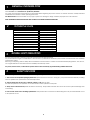
TECHNICAL DATA
Electric Power requirement
220V - 3 PH - 60Hz 15 Amp
Pump motor
Gear-box motor
1.7-2.4 HP (1.3 / 1.8 kw)
Handles rim from
14" - 56"
Max. wheel diameter
90” (2,300 mm)
Max. wheel width
42” (1,065 mm)
Max. wheel weight
3,300 lbs (1,500 kg)
Weight (with standard accessories)
Acoustic pressure level (at work)
3
2.0 HP (1.5 kw)
1,698 lbs (770 Kg)
LpA <70 dB (A)
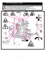
GENERAL SAFETY REGULATIONS
The use of this machine is reserved to specially trained and authorized personnel.
Any unauthorized changes or modifications to the machine, in particular to its electric system, relieve the manifacturer from all liability
and warranty claims.
Removing or tampering with the safety devices installed on this machine is a violation of International Safety Regulations, and, as such,
once again relieves the manufacturer from all liability and warranty claims.
Any work, however minor, on the electric system must be done exclusively by professionally qualified electrician.
4
SAFETY DEVICES
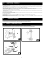
The tire changer has a number of safety devices designed to guarantee the utmost operator safety:
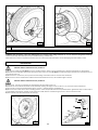
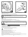
1. Check valve on the spindle opening hydraulic line (inside the swivel connector, see fig. B/1). This prevents the tire assembly off falling
from the spindle if the hydraulic line is accidentally broken.
2. Pressure relief valve factory set at 1,885 PSI (130 bar) ±10% (See Fig. B/2).
This limits the pressure in the hydraulic circuit and ensure correct operation of the plant.
3. Pump motor overload shut-off (inside the electric enclosure). This provides automatic shut-off for the motor to prevent damage from
overheating.
4. Check valve on the chuck arm lifting hydraulic line. This prevents the chuck arm from descending when any accidental break occurs
in the hydraulic circuit.