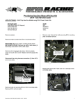
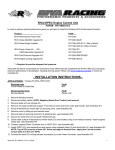
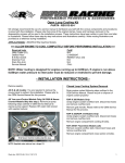
1
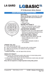
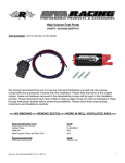
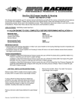
Fuel Pressure Regulator Kit
PART# - RS12050-RRFPR-07
APPLICATION(S): `07 & Older 215hp Sea-Doo Models
∗∗∗ NO SMOKING – ALLOW ENGINE TO COOL COMPLETELY ∗∗∗
Required tools
1/4” Drill Bit
1/2” Drill Bit
19mm Combo Wrench
6mm Allen Wrench
Oetiker Pliers
Start Hex Bit Set
Part#
N/A
N/A
N/A
N/A
C-48550347
RS35187
Recommended tools
OEM Service Manual
Part#
Please Call
We strongly recommend the use of a service manual to familiarize yourself with the various
components and procedures involved with this installation. Please note that some of the
original clamps, hoses and hardware removed in the disassembly process will be used in the
installation process. These instructions have been written in point form and refer to
illustrations. Please follow these step-by-step instructions and illustrations carefully.
NOTE: These installation instructions are broken up into 2 sections. The fuel pressure regulator is
set at 60psi and configured for rising rate. Due to variances in weather and altitude you must verify
pressure is at 60psi when craft is running. To adjust fuel pressure see page 4 of these installation
instructions.
Section 1 outlines the installation process for the complete kit on all 2007
and older Sea-Doo 215hp models. The kit is configured for rising rate at 1
to 1 with a base setting of 60psi. The supplied vent fitting WILL NOT be
used. To adjust fuel pressure setting see page 4 of these installation
instructions.
Section 2 outlines the modifications for rising rate configuration and how to
adjust the base setting. To adjust fuel pressure setting see page 4 of these
installation instructions.
Should you choose to configure the kit for static fuel pressure replace the barbed fitting on the
regulator with the supplied vent fitting.
Word doc. RS12050-RRFPR-08 © H1 3/24/10
1
- SECTION 1 INSTALLATION INSTRUCTIONS Remove seats. RXP models remove engine cowling (5
bolts).
Remove clip1 securing stock fuel pressure regulator to
top of fuel pump.
Remove glove box by unsnapping clips (2) at edge
closest to seat.
1
RXP
Remove fuel pressure regulator by lifting upward. It may
be necessary to pry apart. Take care not to damage top
of fuel pump.
NOTE: Keep a shop rag handy to prevent fuel spill.
Place fuel pressure regulator on a shop rag. Disconnect
fuel supply hose connector1 by squeezing clips (2)
together while pulling on hose.
1
RXT/GTX-SC
RXP must remove hood cowling clips. Pry away from
glove box carefully.
NOTE: Cover fuel supply hose connector with a shop rag to
prevent fuel spill.
Remove supply hose connecting clip from stock fuel
pressure regulator.
RXP
Remove air inlet hoses to gain access to top of fuel
tank.
Word doc. RS12050-RRFPR-08 © H1 3/24/10
2
At front of engine compartment opening measure and
mark two spots exactly 1-7/16” apart.
Install the fuel supply hose connector clip onto the fitting
on left side of RIVA Fuel Pressure Regulator.
Mark first
spot 2-1/4”
away.
Connect the stock fuel hose (from motor) to the fitting
making sure it is securely snapped into place.
RXP: Mark first spot 2-1/4” to the left of engine cowling bolt hole
center.
Apply a thin coat of engine oil to o-rings on billet fuel
supply/return manifold. Install into top of fuel pump so
that brass fittings with hoses face right side of craft.
RXT/GTX-SC: Mark spots in center of engine compartment flange.
Drill 1/4” holes in center of flat area.
1-7/16”
Apart
Replace clip making sure it is securely snapped into
place.
Secure hoses to steering cable using supplied medium
zip tie.
- SECTION 2 RISING RATE MODIFICATIONS Using supplied hardware (M6 bolts, washers & nuts)
mount fuel pressure regulator.
Craft NOT equipped with a Blow-off Valve:
Disconnect ECU electrical connectors (2).
Remove bolts (4) securing ECU to mounting bracket.
Remove bolts (4) securing ECU mounting bracket to
intake manifold.
Using supplied 3/32” drill bit slowly drill into center of
boss on intake manifold that was under right edge of
ECU mounting bracket.
Word doc. RS12050-RRFPR-08 © H1 3/24/10
3
2.
Using a 9/16” combo wrench loosen the jam nut
securing the adjustment screw.
3. Hook craft up to flush kit.
4. Start craft’s engine and allow to idle.
5. Start water flowing to flush kit.
6. To increase fuel pressure slowly rotate adjustment
screw clockwise. To reduce slowly rotate counter
clockwise.
7. Tighten jam nut.
8. Rev engine up 2~3 times and allow to return to
idle. Verify gauge is reading desired pressure.
9. Turn water off.
10. Turn engine off.
Install one end of supplied vacuum hose onto boss and
secure with supplied small zip tie. Route hose forward
along wiring harness to fuel pressure regulator. Install
open end onto barbed fitting on fuel pressure regulator
and secure with supplied small zip tie.
INCREASE
DECREASE
Remember, the water belongs to everyone.
Craft equipped with a Blow-off Valve:
Splice supplied ‘T’ fitting into vacuum line and secure
with supplied small zip ties. Connect ‘T’ fitting to fuel
pressure regulator using supplied vacuum hose and
secure using supplied small zip ties.
Please ride responsibly and respect the environment!
Technical Support
For answers to questions regarding installation or trouble
shooting RIVA Performance Products contact:
RIVA Technical Support directly at (954) 247-0705 or by email at [email protected].
Limited Warranty
RIVA Fuel Pressure Regulator Kits carry a 6-month limited warranty to the
original purchaser. They are warranted to be free of defects in materials and
workmanship under normal use and service. Customer modified components
will be void of warranty. This warranty is limited to defects in the primary
components only. Finish and/or wear marks in or on primary components are
not covered under this warranty.
- Fuel Pressure Setting Instructions & Guide The fuel pressure regulator is set at a static 60psi. Due
to variances in weather and altitude you must verify
pressure is at 60psi when craft is running. In the Rising
Rate configuration pressure is raised at a ratio of 1:1.
Fuel pressure increases 1 pound for every 1 pound of
boost.
1.
Using a 3/16” allen wrench secure adjustment
screw.
Word doc. RS12050-RRFPR-08 © H1 3/24/10
RIVA Racing’s liability is expressly limited to the repair or replacement of the
components contained within or associated with this kit. RIVA Racing agrees to
repair or at RIVA’s option, replace any defective unit without charge, if product
is returned to RIVA Racing freight prepaid within the warranty period. Any
equipment returned which, in RIVA’s opinion, has been subjected to misuse,
abuse, overheating or accident shall not be covered by this warranty.
RIVA Racing shall have no liability for special, incidental or consequential
damages or injury to persons or property from any cause arising from the sale,
installation or use of this product.
No other warranty, express or implied, including, but not limited to the implied
warranties of merchantability and fitness for a particular purpose, applies.
Various states do not allow for the limitation of incidental or consequential
damages and therefore the above exclusion or limitation may not apply to you.
Warranty does not include the expenses related to freight or transportation of
parts or compensation for any inconvenience or loss of use while being
repaired. A copy of the original invoice and a Return Authorization Number
(RA#) must accompany all warranty claims.
Warranted replacement parts will be returned freight collect.
4