1
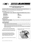
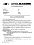
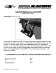
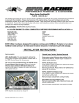
Rear Exhaust Kit PART# - RS15100-2 We strongly recommend the use of a service manual to familiarize yourself with the various components and procedures involved with this installation. Please note that some of the original clamps, hoses and hardware removed in the disassembly process will be used in the installation process. These instructions have been written in point form and refer to illustrations. Please follow these step-by-step instructions and illustrations carefully. APPLICATION(S): Sea-Doo RXT/GTX (S3) iControl Models (Suspended & Fixed Deck) except RXT-X aS 260. NOTE: iS suspension models require RIVA Rear Storage Bucket (part # RS15090-RSB) to complete installation. ALLOW ENGINE TO COOL COMPLETELY BEFORE PERFORMING INSTALLATION Required Specialty Tools Dremmel®, Roto Zip® or Die Grinder Sea-Doo Service Manual INSTALLATION INSTRUCTIONS iS/aS Suspension Models: Remove moving deck. Refer to OEM Service Manual. Part# N/A Please Call 2010 Models: Release latches (5) securing air intake silencer cover. Non-Suspension Models: Raise Seat. Cover Remove bolts (2) securing engine coolant overflow tank to seat bridge. Remove bolts (4) securing seat bridge to hull. Seat Bridge Bolts (4) Latches (5) Lift cover and pull forward to gain access to blow-by hose. Remove hose. Set lid aside. Coolant Tank Bolts (2) Seat Bridge Blow-by Hose Word doc. Part # RS15100-2 © H1 4/25/13 1 Remove air intake silencer baffle (pull up). Set aside. Remove bolts (2) securing air intake silencer to motor. Silencer Remove rubber straps (3) securing air intake tube. Remove air intake tube. Set aside. Squeeze outlet hose inside air intake silencer. Remove air intake silencer by lifting up. Set aside. All Models: At rear of craft remove right deck hatch or storage bucket to access battery. Unclip diagnostic cable connector from battery holder. Remove battery cables. Black first. Red second. Word doc. Part # RS15100-2 © H1 4/25/13 2 Separate electrical component support from battery holder by prying top of support forward. Remove exhaust hose between exhaust muffler (water box) and exhaust baffle. Retain hose clamps (2). Exhaust Hose Remove bolt securing exhaust baffle to hull. Remove bolts (2) securing battery holder to hull. Remove battery holder. Loosen clamp securing exhaust outlet hose to exhaust baffle. Exhaust Baffle Pull exhaust baffle forward to remove from exhaust outlet. Twist baffle to flip over. Remove baffle. Exhaust Baffle TIP: Spray glass cleaner onto hoses to make removal easier. Word doc. Part # RS15100-2 © H1 4/25/13 3 Remove exhaust outlet hose from exhaust outlet. Install supplied block-off and secure with supplied clamp. NOTE: Do not over tighten clamp. Modify washers as seen below. Replace washers with flat side facing downward towards bottom of craft. Secure with stock nut. NOTE: Do not over tighten nut. At rear of craft remove left deck hatch or storage bucket to access intercooler hoses. On left side of transom install supplied template (last page of instructions). Disconnect hoses (2) attached to intercooler. Disconnect IC End Only Remove & Discard Locate bolt holes with a pen or marker. Completely remove shorter of two hoses and discard. Retain hose clamps (2). Using a short straight edge draw two diagonal intersecting lines between bolt holes. Remove lower nut and washers (2) securing tie down cleat to hull. Mark hull at center of shaded circle (cross-hairs) using a punch or scribe. Word doc. Part # RS15100-2 © H1 4/25/13 4 Remove template and create opening for Rear Exhaust Outlet using a 2-3/4” hole saw bit. If using a smaller size hole saw bit we recommend cutting out shaded circle of template after locating center on hull and tracing circle to indicate maximum hole size. NOTE: Do not exceed 2-3/4” in diameter. Install supplied billet exhaust outlet from outside and align so that ‘R’ logo is at bottom (6 o’clock). Drill bolt holes (4). Remove outlet. Thoroughly clean inside and outside of hull. 2012 & NEWER BOLT LOCATION REFERENCE: 1 2 3 4 Secure outlet using supplied bolts (4). NOTE: Apply blue Loctite to bolts. Do not over tighten bolts. TORQUE SEQUENCE: Tighten bolts in a criss-cross sequence turning each one 2~3 revolutions at a time until snug. Apply final torque in a criss-cross sequence until tight. Install supplied rubber gasket onto billet exhaust outlet flange. NOTE: DO NOT APPLY SILICONE TO RUBBER GASKET. Install outlet into hull from outside. From inside of hull place supplied billet onto exhaust outlet. 1 3 3 2 2011 & Older Models install with stand-off’s away from hull. 2012 & Newer Models install with stand-off’s against hull. Stand-offs are to be placed at bolt holes 1, 2 & 4. 1 Word doc. Part # RS15100-2 © H1 4/25/13 2 4 WARNING: Over tightening bolts will result in over compressing and distorting rubber gasket. 5 Install supplied cooling hose. Secure end with 90degree bend to ‘T’ fitting at iBR pump assembly using stock hose clamp. Install supplied coupler onto exhaust thru-hull outlet completely. Loosely install stock clamps (2). Install supplied rear exhaust tube straight end first from engine compartment. It will be necessary to twist as you “thread” the tube into place. Install curved end of exhaust tube into water box coupler. Do not secure yet. Thoroughly clean water box outlet with a non-residual cleaner. Install supplied coupler onto water box outlet completely. Secure using stock clamp. NOTE: Do not over tighten clamp. Loosely install second stock clamp over coupler. Align straight end of exhaust tube with exhaust thru-hull oulet. Slide coupler onto exhaust tube. Ensure exhaust tube is properly aligned and curved end of exhaust tube is flush against water box outlet. Tighten all clamps. NOTE: Do not over tighten clamps. Install open end of supplied intercooler cooling hose to lower fitting on intercooler. Secure using stock clamp. NOTE: Do not over tighten clamp. Install open end of stock intercooler cooling hose to upper fitting on intercooler. Secure using stock clamp. NOTE: Do not over tighten clamp. Word doc. Part # RS15100-2 © H1 4/25/13 6 Bind cooling hoses together using 3 of the supplied zip ties. Apply silicone to underside of flange on supplied storage tub. Secure clear syphon tubes (2) to top of Rear Exhaust Tube with remaining supplied zip tie. iS/aS Suspension Models: Modify left storage tub. Draw a line around outside 2-inches below sealing flange. Insert supplied storage tub into stock storage tub flange completely. Remove excess silicone from top edge. Cut off bottom of storage tub. TIP: Use a large gate band saw if available. Place a thin piece of wood under right side of sealing flange (1/2”~3/4” thick). NOTE: Allow silicone to dry for 24-hours before riding. Replace battery holder and electrical component support. Reconnect battery cables. Red first. Black second. iS/aS Suspension Models: Replace moving deck. Replace rear deck hatches or storage buckets. Clean cut edge of storage tub sealing flange. 2010 models: Replace air intake system. Apply silicone to inside of storage tub sealing flange. Check bilge for tools, rags, etc. Run craft on a flush kit to check for proper operation. Word doc. Part # RS15100-2 © H1 4/25/13 7 Remember, the water belongs to everyone. Please ride responsibly and respect the environment! Technical Support For answers to questions regarding installation or trouble shooting RIVA Performance Products contact: RIVA Technical Support directly at (954) 247-0705 or by e-mail at [email protected]. Limited Warranty RIVA Rear Exhaust Kits carry a 90-day limited warranty to the original purchaser. They are warranted to be free of defects in materials and workmanship under normal use and service. Customer modified components will be void of warranty. This warranty is limited to defects in the primary components only. Finish and/or wear marks in or on primary components are not covered under this warranty. RIVA Racing’s liability is expressly limited to the repair or replacement of the components contained within or associated with this kit. RIVA Racing agrees to repair or at RIVA’s option, replace any defective unit without charge, if product is returned to RIVA Racing freight prepaid within the warranty period. Any equipment returned which, in RIVA’s opinion, has been subjected to misuse, abuse, overheating or accident shall not be covered by this warranty. RIVA Racing shall have no liability for special, incidental or consequential damages or injury to persons or property from any cause arising from the sale, installation or use of this product. No other warranty, express or implied, including, but not limited to the implied warranties of merchantability and fitness for a particular purpose, applies. Various states do not allow for the limitation of incidental or consequential damages and therefore the above exclusion or limitation may not apply to you. Warranty does not include the expenses related to freight or transportation of parts or compensation for any inconvenience or loss of use while being repaired. A copy of the original invoice and a Return Authorization Number (RA#) must accompany all warranty claims. Warranted replacement parts will be returned freight collect. Word doc. Part # RS15100-2 © H1 4/25/13 8 Word doc. Part # RS15100-2 © H1 4/25/13 9