1
Sea-Doo 4-TEC Open Loop Cooling Kit
PART# - RS1013-50
We strongly recommend the use of a service manual to familiarize yourself with the various components and procedures
involved with this installation. Please note that some of the original clamps, hoses and hardware removed in the
disassembly process will be used in the installation process. These instructions have been written in point form and refer
to illustrations. Please follow these step-by-step instructions and illustrations carefully. Water routing illustrations are
provided as a reference during installation.
APPLICATION(S): 255/215hp Sea-Doo Models
∗∗∗ ALLOW ENGINE TO COOL COMPLETELY BEFORE PERFORMING INSTALLATION ∗∗∗
Required tools
Oetiker Pliers
E-8 Star Socket
Dremmel Tool
Drain Pan (LG)
Service Manual
Part#
C-84550347
RS90531 (8-pc set)
N/A
N/A
CALL
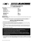
- INSTALLATION INSTRUCTIONS Remove seats.
At pump disconnect steering cable1 and reverse cable2
from steering nozzle. Disconnect VTS rod3 from VTS
motor rod4.
Drain engine coolant following steps outlined in the SeaDoo Vehicle Shop Manual (4-TEC Manual). Please
recycle or dispose of coolant properly!
4
3
Coolant expansion tank holder removal.
RXP-X/RXP Models Only:
Unclip engine coolant overflow tank. Disconnect hoses
and remove overflow tank.
Remove engine compartment cowling (5 bolts).
RXT-X/RXT:
Unclip engine coolant overflow tank. Disconnect hoses
and remove overflow tank.
Remove engine compartment cross section (4 bolts).
2
1
If O.P.A.S. was removed previously proceed to next
step. Otherwise remove bolt securing O.P.A.S. bracket
to underside of steering nozzle.
Word doc. RS1013-50 © H1 12/16/09
1
Remove bolts (4) securing pump assembly to hull.
Remove pump assembly.
Remove rubber boot sealing VTS motor shaft. Remove
nut securing VTS motor unit to hull.
If a RIVA Performance Ride Plate will be installed
proceed to next step. Otherwise, install supplied vinyl
caps over stock ride plate fittings and secure using
supplied zip ties.
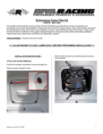
Remove bolts (8) securing thermostat housing to
engine. Remove thermostat housing from engine.
If using a RIVA Pro-Series Water Box proceed to next
step. Otherwise remove exhaust tube between water
box and thru-hull outlet.
2
1
Remove intercooler air inlet and outlet tubes.
Loosen the four bolts securing throttle body to intake
manifold. Remove throttle body and move forward in
engine compartment.
4
3
8
Remove the two bolts securing front of RIVA Power
Filter tube to engine bracket. This will allow you to move
Power Filter tube as needed during installation process.
Inside hull remove VTS motor unit from thru-hull fitting
and move forward in engine compartment.
Disconnect hoses (6) connected to thermostat housing.
Completely remove all hoses except for the two
connected to oil cooler (#’s 3 & 5).
Word doc. RS1013-50 © H1 12/16/09
5
7
6
NOTE: Do not remove impeller from engine.
Transfer o-ring from back of thermostat housing to back
of supplied billet water pump cover.
2
Apply a thin coat of grease to o-ring. Install billet water
pump cover onto engine and secure using OE bolts.
Torque to 89 lbf•in / 10 N•m. NOTE: Apply blue Loctite to bolts.
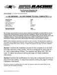
At rear of cylinder head remove the barbed brass fitting
for coolant overflow hose. Install supplied stainless steel
block-off screw.
2
1
215hp Models Only: Locate and completely remove
the cooling lines from transom to intercooler and from
intercooler to exhaust manifold.
Locate and remove 3/8” waterline between top of ‘J’
pipe and transom1.
NOTE: Apply pipe thread sealant to threads. Tighten screw until
head is flush with cylinder head.
1
Install supplied thermostat unit onto rear of cylinder
head. Secure using the supplied 47.0 Oetiker.
Install supplied 3/4” bypass fitting.
Cooling Line Removal:
255hp Models Only: Locate and completely remove
cooling lines with ‘T’ fitting coming in from transom to
intercooler and exhaust manifold1 as well as cooling
lines with ‘T’ fitting going to transom from exhaust
manifold and intercooler2.
Word doc. RS1013-50 © H1 12/16/09
NOTE: Enough cooling line is provided so that bypass can be
installed in transom near rear exhaust outlet. However, bypass
can be installed in pump transom tunnel if desired.
3
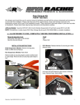
Install supplied 3/4” cooling line assembly (labeled ‘A’)
between the intercooler and motor. The 15” length1
attaches to billet water pump cover. Secure with stock
hose clamp. The 33” length2 attaches to fitting at front of
exhaust manifold (route under drive shaft and motor).
Secure with stock hose clamp.
1
2
2
3
1- Line in to intercooler from transom/flush kit.
2- Line out from intercooler to motor.
1
Replace intercooler and secure to support bracket.
Route open end (14” length3) towards intercooler
support bracket.
Install supplied 3/4” cooling line assembly (labeled ‘B’).
Attach 24” length1 to transom inlet fitting. Route 12”
length2 towards intercooler. Route flush kit3 so it can be
secured in an accessible location.
On right side of engine cut oil cooler lines just before
support bracket1. Install supplied 1/2” x 5/8” brass hose
splicer into each hose and secure using supplied 25.6
Oetikers.
1
2
3
1
NOTE: Larger end of splicer goes into oil cooler hose.
Attach 3/4” cooling lines to intercooler. Secure with
stock hose clamps.
Install supplied 24” length of 1/2” waterline between
lower cooling line1 (oil cooler outlet line) and 3/8”
transom fitting2. Secure to oil cooler line using supplied
21.0 Oetiker. Secure to transom fitting using stock
clamp.
2
1
1
2
Word doc. RS1013-50 © H1 12/16/09
4
Install the supplied 36” length of 1/2” waterline to the
upper cooling line3 (oil cooler inlet line). Secure using
supplied 21.0 Oetiker.
At rear of craft in pump area replace and secure VTS
motor nut. Replace and secure rubber boot sealing VTS
motor shaft. NOTE: Do not over tighten nut.
Replace Power Filter Tube. NOTE: Apply blue Loc-tite
to bolts. Do not over tighten bolts. Do not over
tighten clamps.
Replace throttle body and secure using OE bolts.
NOTE: Torque bolts to 11 N•m (97 lbf•in) in a crisscross pattern.
3
Install 36” length of supplied 3/4” cooling line between
thermostat on cylinder head and 3/4” bypass fitting in
hull. Trim excess as needed. Secure to thermostat
using supplied 30.1 Oetiker. Secure to 3/4” bypass
using stock hose clamp.
Route waterline under drive shaft and towards exhaust
pipe/water box joint.
Attach to applicable fitting (see below) and secure using
stock hose clamp. Trim excess as needed.
Replace supercharger air inlet components. NOTE: Do
not over tighten bolts.
Replace intercooler air inlet and outlet tubes. NOTE: Do
not over tighten bolts.
`08 & newer attach to fitting under end of exhaust manifold.
If using a stock water box replace exhaust outlet tube.
NOTE: Do not over tighten clamps.
At rear of craft in pump area replace OE water inlet
reducer with supplied reducer.
`07 & older attach to fitting at top of ‘J’ pipe (trim excess as
needed). Secure using stock hose clamp.
Replace VTS motor unit into thru-hull fitting making sure
rubber grommet at bottom of housing is installed onto
VTS mounting bracket.
Word doc. RS1013-50 © H1 12/16/09
NOTE: Supplied water reducer has a larger I.D. and is stamped
with an ‘X’ on one side.
5
If a RIVA Performance Ride Plate will be installed
continue with the instructions included with ride plate.
Otherwise, apply glass cleaner to rubber seal on pump
assembly. Install pump into craft and secure using
supplied bolts. NOTE: Apply blue Loc-tite to bolts.
Torque to 31 N•m (23 lbf•ft) in a criss-cross pattern.
RXP-X/RXP Models Only:
Replace engine compartment cowling (5 bolts).
RXT-X/RXT:
Replace engine compartment cross section (4 bolts).
Reconnect VTS rod, reverse cable and steering cable.
NOTE: Do not over tighten bolts.
If O.P.A.S. was removed proceed to next step.
Otherwise, reconnect O.P.A.S. bracket to steering
nozzle. NOTE: Use blue Loc-Tite. Torque bolt to 25
N•m (18 lbf•ft).
Check bilge for tools, rags, etc. Run craft on flush kit to
check for leaks and to ensure smooth operation.
IMPORTANT MAINTENANCE INFORMATION
Flushing: To assure optimal performance with this kit extra care must be used with flushing. The Open Loop flush
connector will be used in place of the stock flush kit fitting in the pump. We strongly recommend the use of a salt
/deposit remover such as Salt-Away® which can be purchased through RIVA Racing’s parts department. When flushing
with a salt/deposit remover do not flush with fresh water afterwards. Allow salt/deposit remover to remain in cooling
system. This will prevent build up of salt or deposits from residual water in cooling system. At the end of your riding
season we recommend “winterizing” your craft if you are unable to ride for an extended period of time.
Sacrificial Anode: Open Loop Cooling Kit water pump cover is equipped with a sacrificial anode. This is to prevent
corrosion from occurring in the motor should you “forget” to flush your craft. However, it is not intended to be used as an
alternative to flushing your craft. Anode will deteriorate over time and should be replaced each season or as needed.
Check anode at beginning and end of riding season. When replacing apply pipe thread sealant to threads and do not
over tighten. Replacement anodes are available through RIVA Racing’s parts department.
Remember, the water belongs to everyone.
Please ride responsibly and respect the environment!
Technical Support
For answers to questions regarding installation or trouble shooting RIVA Performance Products contact:
RIVA Technical Support directly at (954) 247-0705 or by e-mail at [email protected].
Limited Warranty
RIVA Open Loop Cooling Kits carry a 1-year limited warranty to the original purchaser. They are warranted to be free of defects in materials and workmanship under normal
use and service. Customer modified components will be void of warranty. This warranty is limited to defects in the primary components only. Finish and/or wear marks in or
on primary components are not covered under this warranty.
RIVA Racing’s liability is expressly limited to the repair or replacement of the components contained within or associated with this kit. RIVA Racing agrees to repair or at
RIVA’s option, replace any defective unit without charge, if product is returned to RIVA Racing freight prepaid within the warranty period. Any equipment returned which, in
RIVA’s opinion, has been subjected to misuse, abuse, overheating or accident shall not be covered by this warranty.
RIVA Racing shall have no liability for special, incidental or consequential damages or injury to persons or property from any cause arising from the sale, installation or use
of this product.
No other warranty, express or implied, including, but not limited to the implied warranties of merchantability and fitness for a particular purpose, applies. Various states do
not allow for the limitation of incidental or consequential damages and therefore the above exclusion or limitation may not apply to you.
Warranty does not include the expenses related to freight or transportation of parts or compensation for any inconvenience or loss of use while being repaired. A copy of
the original invoice and a Return Authorization Number (RA#) must accompany all warranty claims.
Warranted replacement parts will be returned freight collect.
Word doc. RS1013-50 © H1 12/16/09
6
255hp Intercooler Upgrade Kit & 215hp GEN-2 Power Cooler Kit
Water Routing Illustration
PUMP / TRANSOM
Supplied 3/4"
Bypass Fitting
3/4"0.D. x 24" L
3/4"0.D. x 24" L
COOLING
LINE 'B'
1/2"0.D. x 32" L
31.0
FLUSH KIT
FITTING
THERMOSTAT
UNIT
21.0
47.0
WATER PUMP
COVER
WATER
OUTLET
21.0
3/4"0.D. x 33" L
25.6
3/4"0.D. x 16" L
1/2"0.D. x 24" L
COOLING
LINE 'A'
3/4"0.D. x 33" L
3/4"0.D. x 42" L
3/4"0.D. x 36" L
GEN-2
INTERCOOLER
3/4"0.D. x 15" L
3/4"0.D. x 12" L
= Supplied Oetiker Clamp
= OE Hose Clamp
= Supplied Barbed Hose Splicer
CYLINDER HEAD
INTAKE MANIFOLD
EXHAUST MANIFOLD
OIL COOLER
25.6
215hp GEN-1 Power Cooler Kit
Water Routing Illustration
Supplied 3/4"
Bypass Fitting
PUMP / TRANSOM
GEN-1
INTERCOOLER
3/4"0.D. x 24" L
3/4"0.D. x 24" L
3/4"0.D. x 16" L
3/4"0.D. x 42" L
'J' Pipe
1/2"0.D. x 12" L
3/4"0.D. x 15" L
1/2"0.D. x 24" L
1/2"0.D. x 36" L
COOLING
LINE 'B'
FLUSH KIT
FITTING
3/4"0.D. x 33" L
COOLING
LINE 'A'
31.0
THERMOSTAT
UNIT
21.0
47.0
WATER PUMP
COVER
WATER
OUTLET
21.0
3/4"0.D. x 33" L
25.6
= Supplied Oetiker Clamp
= OE Hose Clamp
= Supplied Barbed Hose Splicer
CYLINDER HEAD
INTAKE MANIFOLD
EXHAUST MANIFOLD
OIL COOLER
25.6