1
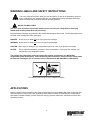
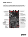
Blood Plasma Freezer With Master Controller For Model BCLZR10AC Installation & Operations Manual An Electronic Microprocessor-Based Electric Expansion Valve Refrigeration Control System Featuring Reverse Cycle Defrost IMPORTANT NOTICES • Read this manual before installing your Master Controller system. Keep the manual and refer to it before doing any service on the equipment. Failure to do so may result in personal injury or waive warranty of damaged equipment. • Modifications to existing equipment are subject to approval by Master-Bilt and must be explicitly written. There are no implied flexibilities designed into this product. • The following points apply unless overwritten and approved by the Master-Bilt engineering department: o Maximum distance of wires between the evaporator and the Master Controller MUST not exceed 40 FT. o The Master Controller MUST be mounted in close proximity to the vestibule entrance door. o All control wiring (i.e. sensor wires, pressure transducer wires, and Electronic Expansion Valve) must be in separate conduit from the power supply. Blood Plasma Room Only. • Due to continuous product enhancements, Master-Bilt reserves the right to make engineering changes and change specifications for product improvement without notice. 2 INTRODUCTION .................................................................................................................. 4 WARNING LABELS AND SAFETY INSTRUCTIONS .......................................................... 5 APPLICATIONS.................................................................................................................... 5 MASTER CONTROLLER ..................................................................................................... 6 Description ................................................................................................................. 6 Factory-Mounted Parts............................................................................................... 9 Features..................................................................................................................... 9 Sequences of Operation .......................................................................................... 10 START UP ......................................................................................................... 10 OFF MODE ........................................................................................................ 10 COOL MODE ...................................................................................................... 10 DEFROST MODE ................................................................................................. 11 Scheduled Defrost ..................................................................................... 11 Manual Defrost ......................................................................................... 11 COIL DRAIN MODE .............................................................................................. 11 FAN DELAY MODE ............................................................................................... 12 SAFETY MODE ................................................................................................... 12 Definition of On-Board Symbols............................................................................... 13 STATUS, DEFAULT AND READING DISPLAY ............................................................... 13 Typical Set Points for Blood Plasma Control Board................................................. 14 Alarm Display........................................................................................................... 15 Setting Parameters by On-Board Pushbuttons ........................................................ 15 Temperature Sensors .............................................................................................. 16 SENSOR SERVICE INSTRUCTIONS ........................................................................ 16 Pressure Transducer .............................................................................................. 17 Charging the Master Controller Refrigeration System.............................................. 18 Technical Notes ....................................................................................................... 18 Electrical Wiring ................................................ 19 TYPICAL WIRING DIAGRAMS ................................................................................. 20 Line Sizing and Insulation…………………………………………………………………22 Start-Up Checklist………………………………………………………………………….22 REVERSE CYCLE DEFROST ........................................................................................... 23 General Information ................................................................................................. 23 Advantages .............................................................................................................. 23 Factory-Installed Parts ............................................................................................. 23 Eliminated Parts....................................................................................................... 24 Defrost Time ............................................................................................................ 24 Charging a Master Controller System Equipped with Reverse Cycle Defrost .......... 24 TROUBLESHOOTING GUIDE ........................................................................................... 25 Troubleshooting Electric Expansion Valve .............................................................. 26 MASTER-BILT PART NUMBERS....................................................................................... 26 3 INTRODUCTION Thank you for purchasing a Master-Bilt Master Controller electric expansion valve refrigeration system. This manual contains important instructions for installing, using and servicing the system as well as a parts list. Read this manual carefully before installing or servicing your equipment. DANGER Improper or faulty hook-up of electrical components of the refrigeration units can result in severe injury or death. All electrical wiring hook-ups must be done in accordance with all applicable local, regional or national standards. NOTICE Installation and service of the refrigeration and electrical components must be performed by a refrigeration mechanic and/or a licensed electrician. The portions of this manual covering refrigeration and electrical components contain technical instructions intended only for persons qualified to perform refrigeration and electrical work. This manual cannot cover every installation, use or service situation. If you need additional information, call or write us: Customer Service Department Master-Bilt Products Highway 15 North New Albany, MS 38652 Phone: 800-684-8988 Fax: 800- 684-8988 Email: [email protected] 4 WARNING LABELS AND SAFETY INSTRUCTIONS This is the safety-alert symbol. When you see this symbol, be alert to the potential for personal injury or damage to your equipment. Be sure you understand all safety messages and always follow recommended precautions and safe operating practices. NOTICE TO EMPLOYERS You must make sure that everyone who installs, uses or services your refrigeration is thoroughly familiar with all safety information and procedures. Important safety information is presented in this section and throughout the manual. The following signal words are used in the warnings and safety messages: DANGER: Severe injury or death will occur if you ignore the message. WARNING: Severe injury or death can occur if you ignore the message. CAUTION: Minor injury or damage to your refrigeration system can occur if you ignore the message. NOTICE: This is important installation, operation or service information. If you ignore the message, you may damage your refrigeration system. The warning and safety labels shown throughout this manual are placed on your Master-Bilt refrigeration system at the factory. Follow all warning label instructions. If any warning or safety labels become lost or damaged, call our customer service department at 800-684-8988 for replacements. This label is located on the cover of a Master Controller. APPLICATIONS Master Controller electric expansion valve systems are designed to control Master-Bilt made condensing units and evaporators for freezer and cooler applications. Each system contains a condensing unit, evaporator(s) with Master Controller board(s), electric expansion valve(s), pressure transducers, temperature sensors and operational controls. 5 MASTER CONTROLLER Description The Master Controller is a custom-designed microprocessor-based electronic controller for Master-Bilt refrigeration products to control an electric expansion valve in response to evaporator superheat and return air temperature. The hardware and input/output descriptions and connections of a Master controller are shown below on Figure 1. Figure 1 . Master Controller 6 • SEI or SER Terminals. Sporlan SEI and SER type electric expansion valves are currently used for all applications. There are 1596 nominal steps for entire valve stroke. • Off Mode Switch is a digital input ‘DI2’. Shorting of pins tells controller to shut everything off for 45 minutes. The defrost heaters, evaporator fans, and output to control the relay for the compressor are turned off. The valve is also shut. An open between the pins of ‘DI2’ tells the controller to run in normal operation. “FF” will appear on the two digeit LED display when the Off Mode is initiated. • Suction Pressure Transducer is mounted at the evaporator suction header to measure saturated suction pressure in absolute value but displayed in gauge pressure in PSIG. The suction pressure is converted to evaporating temperature. The difference between outlet temperature and evaporating temperature is the superheat displayed as “SH”. • High Pressure Transducer is mounted on the condenser and used to monitor both high pressure during cool mode and suction pressure during defrost. • Defrost Termination Temperature Sensor TS1 is mounted downstream of the distributor tube after the valve and close enough to the evaporator coil to measure defrost termination temperature during defrost cylce. Figure 2 on the next page shows the sensor locations of the evaporator and the controller. • Outlet/Fan Cut-In Temperature Sensor TS2 is mounted on the suction line about 6” to 8” away from the evaporator to measure outlet temperature during cooling cycle and to serve as evaporator fan cutin temperature sensor. The sensor is at a 2 or 10 o’clock position on the suction line. The default value o of the fan cut-in temperature (FS or FDSP) is pre-set at -20 F for Blood Plasma Storage Applications. This value may be adjusted depending on respective situations. • Room Temperature Sensor TS3 is mounted at the drain pan on the air intake side of the evaporator. It is located around the center of the evaporator to allow even air flow across it. If necessary, it may be relocated to a spot with better representation of the cold room temperature. • Compressor Suction Temperature Sensor TS4 is mounted at the suction line just prior to entering the compressor. It is used to measure compressor return gas superheat. • Two Digit LED Display is used to show status of the controller, set point values and temperatures. • Green and Red LED Status Indicators. When power is applied to the controller, the green LED will be on constantly during normal operation. The red LED is the negative sign for temperatures showing o less than 0 F on the two digit LED display. If the red LED is off, the two digit display reading is between o o 0 to 99 F. If it is on, the 2 digit display reading is between –55 to –1 F. A blinking red LED indicates an alarm has occurred. • Two Push Buttons are used to display set points and status as well as to reset operational parameters like room temperature, defrost mode, number of defrosts per day, etc. Once an operational parameter has been changed for a given setpoint, no confirmation inputs are required, the Master Controller will recognized these changes immediately. Their functions can also be viewed/changed by an optional remote display panel. • Two 20 Amp, 240 VAC NC/NO Relays. Relay ‘K1’ is used for the drain pan heater when the heater load is less than 20 amp. It will be wired to defrost heater contactor coil when heater load is over 20 amp or three phase heaters. Relay ‘K2’ is used to switch evaporator fans ON and OFF. A fan contactor will be used if the fan motor is lager than 10 amps or three phase or the voltage is different from control voltage. 7 • One 5 Amp, 240 VAC NC/NO Relay is an option for an external alarm system. The customer will decide what type of a physical alarm is used. This relay is energized when the controller is powered on. Whenever the controller gives an alarm, the relay will be de-energized. For example, a technician can connect a phone alarm system to this relay. When there is an alarm, the alarm system can dial in his pager or cellular phone. • Panel Display Jack. When a remote display panel is used for a standalone Master Controller system, this jack is used to connect the remote panel display with a communication cable supplied by the factory. • Power Input 24 VAC 40 VA. The Master Controller power input requirment is 24VAC. A factory mounted 40VA step down transformer is provided at the evaporator. Secondary voltage (24VAC) must be connected to the control board by the refrigeration technician. Evap out / Fan Delay Temp Sensor Pressure Transducer Defrost Term. Temp. Sensor Evaporator Liquid Line Electric Expansion Valve Suction Line Distributor Room Temp Sensor Optional Off Mode Switch Pressure Transducer MASTER CONTROLLER Figure 2. 8 Factory-Mounted Parts • • • The Electronic Expansion Valve (EEV), pressure transducer, and 2 ea. 40VA transformers will be mounted at the factory. Three temperature sensors (TS1, TS2, and TS3) are mounted but not connected to the Master Controller.The EEV, pressure transducer, and 24 VAC supply power must also be connected once the controller is mounted. This should be done by the refrigeration technician. An external relay (12VDC Coil) is mounted at the condensing unit. When in the cooling or defrost mode, this relay will be energized. This relay will then energize the compressor contactor. All components are factory tested. A technician should check all the settings for proper operation after installation. Features • • • • • • • • • • • Free floating head pressure saves energy. The Head pressure control is not installed on Master-Bilt Master Controller systems. Without this control, compressors work at the highest efficiency at the lowest possible condensing pressure rather than at the limited pressure level typically found in conventional systems using a head pressure control valve for low ambient environments. The electric expansion valve replaces a thermal expansion valve. The refrigerant flow of the electric expansion valve is modulated by the true superheat, or the difference of evaporator outlet and evaporating temperatures. The room temperature sensor replaces the conventional temperature control. The temperature is set with the two pushbuttons on the Master Controller board. The default temperature must be checked during the first startup of the machine against actual application temperature. Default must be re-set to actual application temperature if there is a discrepancy. NOTE: This is an extremely low temp application which requires staging the pull down upon the initial start-up. This Blood Plasma refrigeration system should be set to -10º and be left alone for 24 hours. If the high alarm setpoint (HA) has not been reset to accommodate this higher room temp setting, a High Temp Alarm will occur (HA). This can be cleared easily by pressing PB1 on the control board three times consecutively. After the initial pull down, the room temperature set point may then be taken down to -30ºF and left for 12 hours after which the box temperature may be taken to -45ºF. This staging helps prevent freezer panels from delamination. The on-board timer is used for run time control and scheduling defrosts. No mechanical defrost timer is necessary for this system. Number of defrost per day may be set on the Master Controller via the number of defrost per day (nD) parameter. The operational status of modes, room temperature and alarms is displayed on the two-digit on-board display. Manual defrost is available on both the Ante Room and the Blood Plasma Room. A manual defrost may be accomplished by holding PB2 down for more than 5 seconds. o The superheat set point has a wide 2° to 20 F adjustability range. This range allows the controller to meet different customers’ needs, and requires less refrigerant charge for winter operation than conventional refrigeration unit when no head pressure valve is installed in the condensing unit. The unique, patented reverse cycle defrost option (United States Patent 7,073,344) reduces defrost energy usage by 80% and reduces defrost time from 20-45 minutes to 5-10 minutes with a completely clean defrost. Maximum operating suction pressure can be controlled by the electric expansion valve eliminating the crankcase pressure regulator for some applications. Minimum operating suction pressure provides additional compressor protection. The off mode switch turns off the evaporator fans during loading or unloading of refrigerated items. If the off mode swith is left closed for 45 minutes, it will then go back into its normal operating mode. 9 Sequences of Operation START UP When power is applied to the board, the controller closes the valve. The controller will display ‘SU’ on its twodigit display for five seconds. It will then display ‘CF’ on the two-digit display for 10 seconds. The evaporator fans will be on for the first 15 seconds allowing a service technician time to check them. The controller will then turn the fans off and check each sensor. The controller will check the pressure transducer for a short or open. It will display ‘CP’ on the two-digit display for three seconds. If the sensor fails, the controller will display an alarm and go to safety mode for a failed sensor. If the sensor passes, it will display ‘oP’ on the two-digit display for three seconds. The controller will check the sensor connected to ‘TS1’ for a short or an open. It will display ‘C1’ on the two-digit display for three seconds. If the sensor fails, the controller will display the alarm ‘Si’ on the two-digit display and go to safety mode for a failed inlet sensor. If the sensor passes, it will display ‘o1’ on the two-digit display for three seconds. The controller will check the sensor connected to ‘TS2’ for a short or an open. It will display ‘C2’ on the two-digit display for three seconds. If the sensor fails, the controller will display the alarm ‘So’ on the two-digit display and go to safety mode for a failed outlet sensor. If the sensor passes, it will display ‘o2’ on the two-digit display for three seconds. The controller will check the sensor connected to ‘TS3’ for a short or an open. It will display ‘C3’ on the two-digit display for three seconds. If the sensor fails, it will display the alarm ‘SA’ on the two-digit display and go to safety mode for a failed room temperature sensor. If the sensor passes, it will display ‘o3’ on the two-digit display for three seconds. If all sensors pass, the controller will display ‘FH’ on the two-digit display for six seconds. When sensor fails, the alarm relay will be de-energized. The controller will not go into defrost during the preceding start up procedure. It will check the number of defrosts per day (nd) and time_of_day (TIME). If it is time for the controller to be in defrost, it will start in DEFROST (Df) mode. If not, the controller will start in COOL(CL) mode after fan delay. The set points are stored in EEPROM (Electrically Erasable Programmable Read Only Memory). Batteries are not required to store the new set points. If 24 VAC power is lost, the set points which were in the controller at that time will be used when power is restored. OFF MODE (oF) The controller starts in OFF mode by fully closing the valve. The controller will keep the valve closed for the minimum OFF Time (oC) in order to keep the compressor in pumpdown or off for a minimum amount of time.When the room temperature reaches the cut-in set point (room temperature set point “rS” plus the temperature difference set point “rP”), the controller goes to COOL mode (CL). While the controller is in OFF mode, it is constantly checking the number of defrosts per day and the time_of_day and calculating the time for defrost. When the time_of_day is right for a defrost, it will immediately go into DEFROST mode right after the current OFF mode. After the Minimum OFF Time has elapsed and the room temperature reaches the Cut-In temperature, the controller will go into COOL mode(CL). While in OFF MODE, the two-digit display on Master will show ‘oF’ for three seconds, ‘ro’ for two seconds, and the numerical display of the room temperature for five seconds. COOL MODE (CL) The controller starts COOL mode by opening the valve. The condensing unit will start by a suction line low pressure control cut-in. The electric expansion valve is modulated by the controller so that a preprogrammed superheat set point (SS) is maintained during the refrigeration process. Actual superheat is the temperature difference of the evaporator outlet and the evaporating temperature converted from the reading of the presssure transducer, or Tout-Tsat. The controller will keep modulating the valve so the superheat will equal the superheat set point. Meanwhile, the controller reads also the room air temperature TS3. When the room o temperature is below the room temperature set point (pre-set to -40 F for ultra low temp), it goes back to OFF mode. If the suction pressure is above the maximum operating pressure set point (PS), the valve will modulate to control the pressure at or below the maximum operating pressure set point (PS). When the operating suction pressure is lower than PS, it will go back to superheat control. Suction pressure is used to calculate saturated temperature (Tsat) via the Pressure Transducer. 10 If the suction pressure is below the Minimum pressure set point (Pn), the valve will close and the control signal to the external relay will be turned off. It will resume normal operation when the pressure is above the Minimum pressure set point. While in COOL MODE, the two-digit display on Master will show ‘CL’ for three seconds, ‘ro’ for two seconds, and the numerical display of the room temperature for five seconds. DEFROST MODE (dF) The defrost mode of this controller is somewhat similar to a conventional defrost timer with one exception. This control will termintate the defrost if one of two things happens. If the defrost termination temperature (ds) is reached, the controller will terminate the defrost. However, if the maximum defrost duration (dU) is reached before the termination temperature is achieved, the controller will terminate the defrost. After the defrost has been terminated, the system will go into the coil drip mode. Coil drip mode is another adjustable parameter featured on the Master Controller. This set point (dr) is factor set at 5 minutes. During drip mode, the reversing valve will remain energized with 24 VAC. Scheduled Defrost The following is the description of the scheduled defrost. The time_of_day is really an elapsed counter that counts the number of minutes that have passed. An elapsed count of 0 is 12:00 AM. The count goes up to 1439 which corresponds to 11:59 PM. The counter will then reset to 0. The time of day will be kept as long as the 24 VAC power is connected. If the 24 VAC is turned off, then back on, the time of day will be reset to 0 which corresponds to 12:00 AM. The first defrost start time is an elapsed time of 0 (12:00 AM). The subsequent defrost start times are determined by adding the number of minutes between each defrost to the previous start time until there is a defrost start time for each defrost per day. The number of minutes between each defrost is determined by taking 1440 / number of defrosts per day as set up by the ‘NUMBER OF DEFROSTS (nd)’ set point. When starting a reverse cycle defrost, the K2 relay is energized to turn off the fans while, at the same time, terminals B and W of the controller are de-energized to turn off the compressor. There is a 10 second delay before the K1 relay is energized to switch the four-way reverse valve. Then there is a 30 second waiting period for pressure equalizing. Afterward, terminals B and W are energized to turn the compressor on. Hot gas will be reversed to flow to the evaporator while the electric expansion valve is modulated to start a defrost. The controllers use the inlet sensor ‘TS1’ as the defrost termination sensor. When this temperature gets above the preprogrammed ‘DEFROST TERMINATION TEMPERATURE SET POINT (dS)’ before the preprogrammed ‘MAXIMUM DEFROST TIME (dU)’, the defrost will terminate. Otherwise, it will be terminated when the ‘MAXIMUM DEFROST TIME’ elapses as metioned above. While in DEFROST MODE, the two-digit display will be ‘dF’ for three seconds, ‘dn’ for three seconds, and the numerical display of the temperature reading from sensor TS1 for three seconds. Manual Defrost The controller allows manually-initiated defrost when needed. The manual defrost will be disabled if the evaporator inlet sensor detects the temperature higher than the defrost termination temperature. Operation of the manual defrost will be discussed in a later section. COIL DRAIN MODE (Cd) The controller automatically goes into COIL DRAIN whenever a defrost is terminated. The controller stays in this mode for the preprogrammed ‘DRIP TIME (dr)’. When this time is completed the controller opens the expansion valve and goes into FAN DELAY mode (Fd). While in COIL DRAIN MODE, the two-digit display on the controller will show ‘Cd’ for five seconds, ‘ro’ for three seconds, and the numerical display of the room temperature for three seconds. 11 FAN DELAY MODE (Fd) The controller will pull down the temperature of the evaporator without the fans on until one of the following occurs: The fan delay time (FN) of 0-59 minutes times out or the fan cut-in sensor’s temperature TS2 goes below the fan delay temperature (FS) of -20ºF Please note this parameter (FS) has a range of -55ºF to 83ºF. The controller will then go into COOL mode. While in FAN DELAY MODE, the two-digit display will be ‘Fd’ for three seconds, ‘Fp’ for three seconds, and the numerical display of the temperature reading from sensor TS2 for three seconds. SAFETY MODE When an alarm occurs, such as a sensor failure or a communication alarm, the controller will go into ‘SAFETY MODE’. SAFETY MODE provides minimum refrigeration to the refrigerated room before the corrective action is taken and the alarm is cleared. • Pressure transducer alarm (SP) o Cool mode Valve open for the minimum compressor run time Valve closed for the minimum compressor off time Keep doing above cycle until alarm goes away Ignores maximum pressure control mode • Outlet sensor alarm (So) o Cool mode Valve open for the minimum compressor run time Close valve for the minimum compressor off time Keep doing above cycle until alarm goes away. o Fan delay mode Lets fan delay time out (five minutes) o Defrost Mode If this alarm and defrost term temp sensor alarm, reverse cycel defrost will last only three minutes with valve open; • Box temp sensor alarm (SA) o Cool Mode Run on superheat control for the minimum compressor run time Close valve for the minimum compressor off time Keep doing above cycle until alarm goes away. • Low superheat alarm (LS) o Closes valve and wait for alarm to go away. • High Room Temperature Alarm (rH) The ‘high room temperature alarm’ occurs when the room temperature is above the preprogrammed ‘HIGH TEMPERATURE ALARM (HA)’ for a preprogrammed number of minutes. The alarm is cleared when the room temperature is less than the ‘HIGH TEMPERATURE ALARM’ set point. • Low Room Temperature Alarm (rL) The ‘low room temperature alarm’ occurs when the room temperature is below the preprogrammed ‘LOW TEMPERATURE ALARM (LA)’ for a preprogrammed number of minutes. The alarm is cleared when the room temperature is above the ‘LOW TEMPERATURE ALARM’ set point. • Defrost term temp sensor alarm (Sd) o Defrost mode Open valve until alarm goes away or defrost terminates. If this alarm and outlet temp sensor alarm, defrost will last only three minutes. Use outlet sensor for defrost temperature termination 12 Definition of On-Board Symbols STATUS, DEFAULT AND READING DISPLAY When the on-board green light is on, the controller is in normal operation. When the green light is blinking, a set point is being displayed or ready for change. When the red light is blinking, there is an alarm. The status and the digital data are displayed on the onboard two-digit LED display. Below is a list of the parameters of the operational status. Onboard Two-Digit Display Optional Panel Display Description SU CF CP oP C1 o1 C2 o2 C3 o3 FH Fd FP CL oF dF Cd dn STUP CKFN CKP1 OKP1 CKT1 OKT1 CKT2 OKT2 CKT3 OKT3 CKFH FNDL FDTP COOL OFF DEFR DRIP DFTP Indicates the status of Start Up Mode Check fan working status Check pressure transducer Indicates the pressure transducer is working as it should Check sensor TS1, the inlet/defrost termination temperature sensor Indicates the TS1 is working as it should Check sensor TS2, the outlet/fan cut-in temperature sensor Indicates the TS2 is working Check sensor TS3, the room temperature sensor Indicates the TS3 is working Indicates all sensors are OK Indicates FAN DELAY MODE Actual TS2 value in FAN DELAY Indicates COOL MODE Indicates OFF MODE Indicates DEFROST MODE Indicates COIL DRAIN MODE Inlet sensor TS1 value in DEFROST MODE 13 A list of the parameters that can be displayed and/or changed is shown below when access to the default settings is needed. This access is usually done by a trained technician. The following are outputs only and may not be changed. ro E0 SH CS in oU dE Ct Pr dp RMTP POSN SUPH COSH TSAT TOUT DFTP CMTP PRES DPRS o o room temperature from TS3 (-60 F to +93 F) percentage the valve is open (0 to 99%) actual superheat in COOL MODE (TS2 – in) actual superheat measured at the compressor suction (TS4-in) evaporator saturated temperature calculated from suction pressure Pr evaporator suction outlet temperature from TS2 temperature read from the evaporator defrost termination sensor TS1 temperature read from compressor suction TS4 suction pressure read from the pressure transducer (-14.6 to 138.4PSIG) head pressure during Cool Mode; suction pressure during Defrost Mode in Hexadecimal Digits. Use remote display to read head pressure The following are adjustable parameters. Cn nS SS rS dU dS dr nd HA Ad LA oC rn rP PS Pn HS Ar Fc FS FN SC AL CMMD MSGP SHSP RMSP DFTM DFSP DRTM NMDF HIAL ALDL LOAL OFTM RNTM RNTP MPSP NPSP DPSP LGAD DGCF FDSP FDTM CMSP DIF2 The Standalone, Alternating Mode. Standalone, Ao The address group for communication ( nS=0 ), reserved for future use o superheat set point (5 to 30 F). (SS =10) o o room temperature set point or cut-out (-50 F to +30 F, Default= -45F) maximum defrost duration (0 to 60 minutes). (dU = 20 ) o defrost termination temperature (35 to 90 F). (dS = 50 ) drip time duration (0 to 15 minutes). (dr = 5 ) number of defrosts per day (1 to 12). (nd = 3) o high temperature alarm set point (-40 to +35 F). (Default= - 30F) temperature alarm delay (0 to 59 minutes). ( Ad = 30 ) o low temperature alarm set point (-60 F not adjustable) minimum time the valve is close (0 to 15 minutes). (oC = 2 ) minimum time the valve is open (0 to 15 minutes). (rn = 2 ) o cut-in temperature differential (0 to +25 F). ( rP = 05) Maximum pressure set point (-4.6 to 55 PSIG). Default is 3 PSI Minimum pressure set point (-14.6 to 3 PSIG). Default is -14.6 PSI Suction Pressure Set Point during defrost ( 10 to 80 PSIG). Default = 30 Address of controller for remote data logging ( Ar = 00, not used here ) Temps measured in Degrees C or Degrees F. Default = FA o Fan delay temperature set point (-55 to 30 deg F) -20 F Maximum time to delay fans (0 – 10 Minutes) 5 min o Superheat setpoint at compressor suction ( 15 to 80 F) ( Default = 50) If in alternating mode, number of deg above air set point to override and both o controllers to go into cool mode (0-25 deg F). 5 F Note 1: When power is lost, the backup power is to drive the EEV completely close. Note 2: Compressor CPR valve setting 10 to 15 PSIG. 14 ALARM DISPLAY Any alarm will cause relay #3 to switch. All alarms have a distinct display shown on the two-digit display on the controller. The green LED will be on and the red LED will blink. Multiple alarms can exist. There is a priority as to which alarm will be displayed before another. Onboard 2 Digit Display Optional Panel Display NOAL SP So SA LS rH rL Sd CS dA LP CA PRSR SCSR RMSR LOSH HIRM LORM DFSR CMSR DPSR LPAL CMAL Description PRIORITY Displays when there are no alarms. The onboard 2 digit display will display status and temperature readings pressure transducer evaporator outlet temperature sensor TS2 alarm room temperature sensor TS3 alarm low superheat alarm high room temperature alarm low room temperature alarm defrost termination sensor TS1 alarm Compressor Suction Temperature Sensor Alarm high press transducer alarm Low pressure alarm communication alarm 1 2 3 4 5 6 7 8 9 10 11 Setting Parameters By On-Board Pushbuttons When the two-digit display is a displaying a temperature or status, the green LED is always on. The red LED is the negative sign. When the red LED is on, it indicates the temperature is below zero. When the green light is blinking, a set point is being displayed or ready for change. When the red light is blinking; it indicates an alarm. There are two levels for programming the controllers with the two-digit display and two pushbuttons. The first level (User’s Level) will enable the USER to set the room temperature set point ‘rS’; the second level (Technician’s Level) allows access to the other parameters as described above. USER’s Level Press and hold ‘PB2’ until the display shows ‘rS’ (about five seconds). The green LED will start blinking. The display will toggle between ‘rS’ and the numerical value of the room temperature set point. The red LED will be off if the set point is positive or on if the set point is negative. Press ‘PB1’ to increase the room temperature set point by o o 1 F. Press ‘PB2’ to decrease the room temperature set point by 1 F. The set point can o o be changed between -40 F to +80 F. If no button is pushed for 20 seconds, the controller will go back to normal operation. The green LED will be on constantly and the mode will be displayed as described above. TECHNICIAN’s Level To enter the second level of programming (able to see all temperatures and change all Set points), press and hold ‘PB1’ and ‘PB2’ simultaneously until the display shows ‘ro’ (about five seconds). The green LED will start blinking. The display will toggle between ‘ro’ and the numerical value of the room temperature. The red LED will be off if the set point is positive or on if the set point is negative. To scroll down the parameters without changing them, press ‘PB2’. To increase the set point by one increment, press ‘PB1’. When that set point gets to its maximum value, pressing ‘PB1’ will rotate it to its minimum value. CLEAR ALARM Pressing ‘PB1’ three times within five seconds will cause the controller to clear “LS”, “rH” and “rL” alarms and restart timer. MANUAL DEFROST If the controller is in OFF or COOL MODE, pressing and holding pushbutton PB1 for over five seconds will cause the controller to go into defrost cycle. If the controller is in 15 PUMP DOWN MODE, pressing and holding pushbutton PB1 for over five seconds will cause the controller to go into DEFROST MODE. If the controller is in DEFROST MODE, pressing and holding pushbutton PB1 for over five seconds will cause the controller to go into COIL DRAIN MODE. If the controller is in COIL DRAIN MODE, pressing and holding pushbutton PB1 for over five seconds will cause the controller to go into FAN DELAY MODE. If the controller is in FAN DELAY MODE, pressing and holding pushbutton PB1 for over five seconds will cause the controller to go into COOL MODE. Temperature Sensors o o The application range of the temperature sensors used for this controller is -50 F to +103 F. If the sensor detects a temperature out of the range, an alarm will show on the controller display. Four temperature sensors are used in the Master Controller refrigeration system. They are the room temperature return air sensor, the evaporator defrost termination temperature surface sensor, the evaporator outlet (suction line) temperature surface sensor and a Compressor Suction Return Gas Temperature sensor. All sensors are solid state devices with the same characteristics that change electrical resistance in response to a change in temperature. The room temperature sensor is factory-mounted on the lower back of the evaporator at the drain pan. This placement avoids heat from defrost heaters and lights and still allows a good air stream over the sensor. Figure 3 shows a typical mounting of the room temperature sensor. The defrost termination sensor is mounted on one of the distributor tubes close the coil end plate. The outlet sensor is mounted on the suction line at the outlet Figure 3 of the evaporator as shown in Figure 4. These sensors are interchangeable. SENSOR SERVICE INSTRUCTIONS DEFROST TERMINATION TEMP SENSOR EVAP OUT FAN DELAY TEMP SENSOR PRESSURE TRANSDUCER Care must be taken when brazing the suction line at the evaporator. The outlet sensor must be taken out before brazing. After brazing, fasten the sensor with the metal strap provided. Make sure the sensor is tight and has good contact with the suction line. The temperature sensor cannot be repaired. Using the measurements in Chart A below, you can determine if they are functioning correctly. If the sensors are found out of tolerance, they should be replaced. As mentioned above, the temperature sensor changes electrical resistance in response to temperature changes. Disconnect the sensor from the controller, check the temperature at the sensor location, then check and record the resistance through the temperature sensor. SUCTION LINE 6" TO 10" Figure 4 Procedures to check temperature sensor tolerance with ice water: 1. Use a cup of water with well-stirred ice. The water temperature should be an even 32°F. 2. Submerge the room temperature sensor (TS3) into the water while the Master Controller is normally operating. Check the display for the value. If the sensor shows 32°F, it is working properly. 3. Push PB1 and PB2 simultaneously until the green LED is blinking, scroll down the display to “in”, the defrost termination sensor (TS1) value. Submerge the sensor into the water. Check the display for the value. If the sensor shows 32°F, it is working properly. 4. Scroll down the display to “oU”, the outlet sensor (TS2) value. 5. Submerge the outlet sensor into the water. Check the display for the value. Again, if the sensor shows 32°F, it is working properly. Compare the temperature and resistance to TABLE 1. 16 o TABLE 1: Temperature/Resistance Characteristics (-50 to 80 F) o o o o Temp. F Temp. C ohms*1k Temp. F Temp. C ohms*1k -50 -45.6 43.45 15 -9.4 7.579 -40 -40.0 32.31 20 -6.7 6.731 -35 -37.2 27.96 25 -3.9 5.993 -30 -34.4 24.27 30 -1.1 5.349 -25 -31.7 21.13 32 0 5.123 -20 -28.9 18.43 35 1.7 4.781 -15 -26.1 16.12 40 4.4 4.281 -10 -23.3 14.13 50 10.0 3.454 -5 -20.6 12.42 60 15.6 2.805 0 -17.8 10.94 70 21.1 2.294 5 -15.0 9.651 80 26.7 1.888 10 -12.2 8.544 o NOTE: Use resistance at 32 F for sensor checking. Suction Pressure Transducer The green lead is connected to terminal ‘1-‘ on the board. The white lead is connected to terminal ‘1S’ on the board. The black lead is connected to terminal ‘1+’ on the board. The black wire gets 5 VDC, the white wire is the signal, and the green wire is the ground. TABLE 2 shows the characteristics of the pressure transducer. NOTE: The pressure transducer cannot be repaired but replaced only. TABLE 2: Pressure Sensor Simulation Values ( 0 to 150 PSIA) V PSIG (White to Bar PSIA Green) 0 0 -14.6 0.509 0.69 10 -4.6 0.784 1.379 20 5.4 1.058 2.069 30 15.4 1.332 2.758 40 25.4 1.587 3.448 50 35.4 1.862 4.137 60 45.4 2.136 4.827 70 55.4 2.391 5.516 80 65.4 2.665 6.206 90 75.4 2.920 6.895 100 85.4 3.194 7.585 110 95.4 3.469 8.274 120 105.4 3.724 17 Charging the Master Controller Refrigeration System Note: If you are a first time installer of a Master Controller system, please call MasterBilt for on-phone training. Since the system is built with high compressor EER, the head pressure control valve is not installed in this type of system. During initial pull down, after primary charge while the system is running, a large evaporator superheat is built up. The electric expansion valve is then open all the way. If the system is charged full sight glass during this period, the system is already overcharged. The recommended charging procedures are: (1) Charge the system by weighing exact amount of refrigerant specified by Master-Bilt for the unit. TABLE 3 below give the proper refrigerant charges needed for each Blood Plasma sytem. The refrigerant charge greatly depends on the length of the liquid line. Measure the line set carefully and use the table provided accordingly. TABLE 3: REQUIRED REFRIGERANT FOR RESPECTIVE SYSTEMS Condenser Compressor Evaporator Liquid Line Length (ft) BCLZR10AC 9TH2-101E-TFC EXLRS330B Refrigerant lbs of R-404 A 5 10 15 20 25 30 50 65 75 100 150 Liquid Line Size 13.25 14.31 15.37 16.43 17.49 18.55 22.79 25.97 28.09 33.39 43.99 7/8” Technical Notes • • With the optional alarm relay the external temperature and alarm indicator should be connected to “C” (common) and “NC” (normal close) terminals. The alarm does not indicate what causes the alarm. To find out what has caused the alarm, check the onboard two-digit display for alarm codes and refer to the diagnosis chart for corrective action. No electric current goes through the alarm output circuit. Thermostat wiring can be used for connection. o Defrost termination set point (Ds) can be also set as 50, 70 or 80 F. When setting the defrost termination temperature, make sure that the frost is free after each defrost. Also make adjustments to the maximum defrost duration when necessary. 18 • • • o The superheat of each application can be set by the customer. Superheat 10-15 F is recommended o for winter operation, superheat 5-10 F for summer. Always clear the “LS”, “rH” and “rL” alarms after corrective action is taken. The sensor and communication alarms cannot be cleared unless they are corrected. Follow the instructions in the Master-Bilt Condensing Unit and Refrigeration System Installation & Operation Manual to perform the final check up before charging and starting up the system. Always refer to this service manual, make sure all steps are understood. Don’t hesitate to call Master-Bilt Customer Service Department at 800-684-8988 for technical assistance. Electrical Wiring WARNING Please make sure to turn all power off before servicing electrical equipment. Always use a qualified and trained technician. If you are the technician and a first-time installer of a Master Controller system, call our service department at 800-684-8988 for free training and support. The field wiring for the Master Controller in the Blood Plasma Room is somewhat different from the wiring assosicated for the Ante Room. Since the Blood Plasma Control Board is mounted outside the Walk-in Box, the control wiring will need to be done by the electrical contractor and the refrigeration technician. Please see the wiring diagrams given below for conduit and wiring detail. A large Drawing for each of these is included with your equiipment. Please note that the control wiring between the condenser and the evaporator may be low voltage thermostat wire. All other high voltage wiring must be in compliance with local and national codes. Figures 5 and 6 illustrate the wiring details for the Blood Plasma and Ante Rooms respectivelly. 19 N.O. Component Pressure Relief Port Freezer Door Heat Pass Thru Door Heat Lights (100W each) Voltage 115/60/1 115/60/1 115/60/1 115/60/1 Amps Each 0.46 3.8 1.3 0.87 FIGURE 5: TYPICAL WIRING DIAGRAM FOR BLOOD PLASMA ROOM 20 N.O. Component Pressure Relief Port Freezer Door Heat Pass Thru Door Heat Lights (100W each) Voltage 115/60/1 115/60/1 115/60/1 115/60/1 Amps Each 0.46 3.8 1.3 0.87 FIGURE 6: TYPICAL WIRING DIAGRAM FOR ANTE ROOM 21 Line Sizing and Insulation Table 4 below depicts proper line sizing for each Blood Plasma system offerd by Master-Bilt. There is no room for error when making line size selections and this guideline must be followed. The suction line must be insulated with 1” minimum Armoflex® or equivalent insulation. The insulation must fit the piping properly and all joints and bends be properly glued and sealed. TABLE 4: LINE SIZING FOR BCLZR10AC Condensing Unit Model BCLZR10AC 50' 1 3/8 Suction Line Sizes Liquid Line Sizes Equivalent Length 75' 100' 150' 1 3/8 1 3/8 1 3/8 Equivalent Length 75' 100' 150' 7/8 7/8 7/8 200' 1 3/8 50' 7/8 200' 7/8 Start-Up Check List for Blood Plasma Refrigeration Equipment 1. All refrigerant piping should be complete and in accordance with Master-Bilt sizing selections. Please contact our facility if you are unsure of proper line sizing. Good refrigeration piping practices must be followed. 2. All refrigeration equipment should have reached proper vacuum levels prior to Master-Bilt Engineers arriving on job site. Micron gauges should be left on systems so that Master-Bilt personnel may observe that proper vacuum levels have been reached. 3. For -40ºF rooms, the Master Controller Board should be mounted outside Walk-In box and all electrical conduits and circuits should be complete. Please reference supplied system drawings for proper conduit schedule. 4. All electrical connections should be made. This shall include all EEVs, Pressure Transducers, Temperature Sensors, and all respective power supplies for each refrigeration system. 5. All drain lines should be complete with insulation and drain line heaters wired. Electricity to drain line heaters should be left off until start-up. 6. All lighting, door heaters, and pressure relief ports should be wired and ready to activate upon start-up. 7. Walk-In Boxes should be clear of debris that may have collected during installation process. 22 REVERSE CYCLE DEFROST General Information Master-Bilt’s patented (U.S. patent no. 7,073,344) reverse cycle defrost is an option provided on Master Controller-equipped refrigeration systems only. If your Master Controller refrigeration system is equipped with reverse cycle defrost, a reverse cycle valve is already factory-installed on the condensing unit. The valve’s primary function is to reverse the direction of the refrigerant flow during defrost. Under the normal refrigeration cycle, the refrigerant flow is the same as traditional refrigeration modes. During the defrost mode, the refrigerant flow is reversed back through the evaporator coil heating it from the inside-out along its entire length and completely eliminating frost buildup (see figure 5 below). Figure 5 Advantages Reverse cycle technology offers several significant advantages: • An 80% reduction in defrost energy usage. This savings, coupled with that from the demand defrost feature, dramatically reduces electrical consumption. • Eliminates many mechanical parts • Reduces cost of evaporator, installation and wiring • Reduces defrost time • No noticeable increase in freezer room temperature • Product temperature rise significantly less Factory-Installed Parts A 4-way reversing valve is installed in a reverse cycle defrost unit. The 4-way reversing valve operates at 24 VAC. A transformer is installed in the master evaporaratpr to supply 24VAC to the 4-way reversing valve. 23 Eliminated Parts The Master-Bilt Reverse cycle’s unique technology, coupled with the bi-flow electric expansion valve, eliminates the need for: • Defrost heaters, please note some evaporators will have heater, they are not wired. • Head pressure control valves • Check valves and expansion valves at the condenser that are normally necessary in traditional hot gas defrost systems. Ante Room only! • By-pass valves • Liquid line solenoid valves • Receiver tanks (Ante Room Only) • Sight glasses on Ante Room Only Removing these components reduces the cost of the evaporator itself and saves on installation and wiring. Defrost Time Defrost time is greatly lessened with the reverse cycle option. The average time using traditional defrost heaters is 20-30 minutes but reverse cycle performs a completely “clean” defrost in 5-8 minutes on average. Because the defrost is so rapid, there is no noticeable increase in freezer room temperature and the product temperature rise is also significantly less. Reverse cycle defrost, combined with demand defrost, assures the evaporator receives the number of complete defrosts needed at the necessary times to prevent iced evaporators while assuring the protection of the valued product being stored. Charging a Master Controller System Equipped with Reverse Cycle Defrost Note: If you are a first time installer of a Master Controller system, please call MasterBilt for on-phone training. Since the system is built with high compressor EER, the head pressure control valve is not installed in this type of system. During initial pull down, after primary charge while the system is running, a large evaporator superheat is built up. The electric expansion valve is then open all the way. If the system is charged full sight glass during this period, the system is already overcharged. The recommended charging procedure: In a reverse cycle defrost system, there may not be a liquid receiver. Charge the system at three lbs. per ton of rated cooling capacity to start with. Let the system run through the pull down period until room temperature is closely reached. Then gradually add refrigerant until actual superheat “SH” on board is approaching superheat setpoint “SS”. Bubbles may be left in the sight glass. How to diagnose an overcharged system: An overcharged system will not operate properly. • First, be sure that system is not leaking • Compressor may be short cycling • Frost building up on compressor suction section, suction filter or service valve • Low superheat alarm appears on the controller display constantly Solution: Taking some refrigerant out of the system until on-board actual superheat “SH” is observed approaching superheat setpoint “SS”. Due to the reversing of the refrigerant flow, it is recommended that the refrigeration liquid line piping also be insulated to prevent condensation drips between the condensing unit and the evaporator coil. 24 TROUBLESHOOTING GUIDE Use the alarm display together with the chart below to check the causes of each error message. Trouble, Alarm Codes Causes Corrective Actions Pressure transducer alarm SP, PRSR, dA, DPSR • Bad transducer • Fitting leak • Loose wire • Wrong hook-up NOTE: for DA or DPSR, high side pressure transduce may be out of range (0-500 psig) • Mechanical damage • Connection wire loose • Overheated • Out of range • Replace the pressure transducer • Repair leak • Wire correctly NOTE: for DA or DPSR, HS may need to be raised. Outlet sensor TS2 fails So SCSR Room sensor TS3 fails SA RMSR • • • • • • • • • • • Mechanical damage Connection wire loose Overheated Out of range Superheat setting too low Wrong locations of TS1, TS2 Sensors may be loose Uneven feeding of coil circuits Overcharge of refrigerant Defective electric expansion valve (EEV) Compressor stops Insufficient refrigeration Heat load too large Compressor fails or high pressure cuts out Evaporator fans may not run Door open for too long Coil iced-up Low room temperature rL, LORM Defrost termination sensor TS1 fails Sd. INSR • • • • • • Inproper low temp setpoint Over designed system Mechanical damage Loose connection wire Overheated Out of range Low pressure alarm LP, PAL Communication CA, CMAL • Refrigerant leak • Bad transducer Low superheat LS LOSH • High room temperature rH HIRM • • • • • Tighten the connection wires on the controller terminal • When brazing suction line, take out the sensor • Install the sensor after brazing • Tighten the connection wires on the controller terminal • The room sensor can be replaced by surface sensor • Change to correct set point • Make sure the distributor is feeding each circuit evenly • Insulate the sensors with foam tape • Use correct refrigerant charge • Check EEV wiring • Replace defective EEV • Check compressor • Check system design to select a sufficient system • Replace failed compressor • Fix the evaporator fans • Keep the cold room door closed during refrigeration • Check possible air leak through the walls of cold room • Change low temp set point • Re-select the system • Tighten the connection wires on the controller terminal • Let the sensor cool down to application o o temperature range: –50 F to +103 F • Replace failed sensor • Fix leak • Replace pressure transducer • Loose RS-485 coonection • Failed communication port 25 • Tighten the terminals • Change a new controller board Troubleshooting the Electric Expansion Valve If the valve stops moving, depending upon how far open it is, one or more alarms may be displayed. These alarms include a low superheat alarm, a low temperature alarm, and/or a high temperature alarm. Use the following steps to troubleshoot the valve: 1) Disconnect the valve from the controller. 2) The resistance between the black and white leads should be approx. 90 ohms. The resistance between the black and red leads should be an open. 3) The resistance between the red and green leads should be approx.90 ohms. The resistance between the white and green leads should be an open. 4) The resistance between each lead and the brass housing of the valve should be an open. 5) Read the AC, not DC, voltage across the black and white leads while the valve is moving. The AC voltage should be 11 to 13 VAC. The voltage will be close to 0 VAC when the valve is not moving. 6) Repeat step 5 across the red and green leads. If any voltage is out of tolerance, replace the controller. If the above steps pass, inspect for contamination in the valve or nicks on the seat of the valve. CAUTION: If the valve was taken apart and was left running while taken apart, the piston may have come too far out of the motor assembly. If you reassemble the valve with the piston in this position, the threads in the piston will be stripped when the piston is forced into the seat while tightening the lock nut. Make sure the piston is drawn up far enough into the motor assembly before reassembling. MASTER-BILT PART NUMBERS Use the chart below when ordering replacement parts for your Master-Bilt Master Controller refrigeration system. Item Description Blood Plasma Control Board Ante Room Control Board Electric Expansion Valve for Blood Plasma Room Electric Expansion Valve for Blood Plasma Room Electric Expansion Valve for Ante Room Pressure Transducer for Blood Plasma Room High Pressure Transducer for Blood Plasma Room Pressure Transducer for Ante Room Pressure Transducer for Blood Plasma Room 4-Way Reversing Valve 7.5 HP 4-Way Reversing Valve 12 HP 4-Way Reversing Valve 16 HP 4-Way Reversing Valve 2 HP Evaporator Inlet/Outlet Sensor (Surface Sensor) 24VAC, 40VA Transformer 6 Pin, 25 ft Data Cable Controller Mounting Cover Assembly Remote Panel Display Part Number 19-14096 19-13988 19-14071 19-14072 19-13772 19-13955 19-14092 19-13955 19-14092 09-09819 09-09783 09-09783 09-09776 19-14073 39--01088 19-13780 900-18151 19-13778 Notes Please re-set for applications Please re-set for applications SEI-8.5 X 40, 7/8” X 1 1 1/8” SEI-11 x 40 5/8” x 5/8” SER-6, 3/8" x 1/2" Suction Pressure during Cool Mode Discharge Pressure during Cool Mode Suction Pressure Head Pressure @ Condenser For 7.5 HP only! For 12 and 16 HP only! For 12 and 16 HP only! For 2 HP Ante Room Condenser only! 40 ft Leads 120/208/240 V Primary For use with remote panel display For Ante Room Only Standard Feature effective 05/08 For condensing unit installation and wiring, please consult the Master-Bilt Condensing Unit System Installation and Operation Manual. If any discrepancy is found in this manual, please contact Master-Bilt Technical Service Department immediately. 26 908 Highway 15 North New Albany, MS 38652 Service Dept. phone: 800-684-8988 Fax: 866-882-7629 Email: [email protected] REV 07 Aug 2008, TBC 27