1
V1-91508
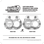
BAKER CRUISE DRIVE 6 SPEED HYDRAULIC SIDE COVER
INSTALLATION INSTRUCTIONS
FEATURES
The new BAKER Hydraulic Side Cover is yet another part that we added to the ever growing
stable of H-D® Cruise Drive 6 Speed compatible parts. We were the first company 10 years ago
to come out with a 6 speed transmission for the Harley Davidson aftermarket, so it only makes
sense that we are the first company to turn to for parts now that The Factory sells 6 speeds right
off of the production line. The Function Formed styling is unmistakably BAKER and follows in the
same foot steps of our Hydraulic Actuators that we have perfected over the years. The vacuum
wrapped side cover is machined from virgin 6061-T6 aircraft grade aluminum, then polished and
chrome plated to a mirror finish. It is an easy install, looks great and using our low profile 1.500”
diameter hydraulic piston the clutch operation will be smooth and effortless every time, for years
to come.
FITMENT (for P/N DD7-106C-KIT)
•
•
•
2006-09 Dyna®
2007-09 Softail®
2007-09 Touring
The BAKER CD6 Hydraulic Side Cover is designed to work with 11/16” Bore Diameter Hydraulic
Clutch Master Cylinders.
PAGE 1 | OVERVIEW
V1-91508
BAKER CRUISE DRIVE 6 SPEED HYDRAULIC SIDE COVER
TABLE OF CONTENTS
2) Table Of Contents
3) Included Parts Breakdown
4) Tools, Resources, Required Parts
5) Disassembly, Start Installation
6) Installation Continued
7) Bleeding The Hydraulic Clutch System
8) Bleeding Steps Continued, Finish line
9) Terms
10) Disclaimer
PAGE 2 | TABLE OF CONTENTS
V1-91508
BAKER CRUISE DRIVE 6 SPEED HYDRAULIC SIDE COVER
INCLUDED PARTS DETAIL
Figure 1
ITEM
QTY
P/N
DESCRIPTION
1
1
37084-84L
Clutch Actuator Rod Assembly (2.815” Overall)
2
2
66855
3
1
124-56L
Hydraulic Piston, 1.500” Diameter, LSD
4
1
DD7-106C
CD6 Hydraulic Side Cover, 1.500” Bore
5
1
94-4508
6
6
2AL1.250-12SL
Hydraulic Piston O-Ring
Bleeder Valve (1/4-28 Thread)
Bolt, ARP™, 12pt, ¼-20 x 1.250” Stainless
PAGE 3 | INCLUDED PARTS DETAIL
V1-91508
BAKER CRUISE DRIVE 6 SPEED HYDRAULIC SIDE COVER
TOOLS, RESOURCES, REQUIRED PARTS
•
Factory Service Manual For Your Motorcycle
•
Factory Parts Manual For Your Motorcycle
•
Common Hand Tools Are All That Is Needed For This Installation
•
In-lbs Torque Wrench
•
Brake Bleeder Pump
•
Transmission Fluid 32 oz Needed, BAKER Recommends:
Spectro™ Heavy Duty Platinum 6 Speed Transmission Oil, P/N R.HDPG6
•
Hydraulic Fluid, BAKER Recommends:
H-D® Dot 5 Brake Fluid, P/N 99902-77
•
AN -3 Brake Line
•
10mm Banjo Fitting for both ends of brake line
•
3/8”-24 Banjo Bolt for the side cover end of the brake line
•
Banjo Fitting Washers
•
11/16” Diameter Bore Hydraulic Clutch Lever Assembly
Quality aftermarket brake lines and fittings can be purchased from your local Drag Specialties™
or Custom Chrome™ Dealers. Or if you prefer shopping on the web, J&P Cycles™ is another
source. All 3 choices have a full selection of parts to match the aesthetic style of your bike,
personality or your budget.
Customers who have CVO™ Model Motorcycles that come with Factory installed Hydraulic Side
Covers will need to purchase the following parts from a H-D® Dealer to be able to use the BAKER
CD6 Hydraulic Side Cover. All of our RSD & LSD Hydraulic Actuators are designed to use
mechanical ball and ramp components for the center rod that goes through the transmission
mainshaft, as well as the release plate, adjuster screw, jam nut and retaining ring that are in the
clutch basket. The BAKER Hydraulic Feed port is designed to work with aftermarket style banjo
fittings and bolts and is not compatible with the CVO™ style straight entry, formed end hydraulic
clutch line.
•
P/N 37092-06
Push Rod, Clutch Release (through mainshaft)
•
P/N 37090-98A
Screw, Adjuster
•
P/N 7848W
Jam Nut
•
P/N 37903-90
Release Plate
•
P/N 37909-90
Retaining Ring, Internal
PAGE 4 | TOOLS, RESOURCES, REQUIRED PARTS
V1-91508
BAKER CRUISE DRIVE 6 SPEED HYDRAULIC SIDE COVER
DISSASSEMBLY
1) With your bike securely supported on a bike lift or jack, drain the transmission fluid. Refer to
your Factory Service Manual for the location of your drain plug.
2) Depending on the style of exhaust that you have on your motorcycle, the exhaust may need to
be removed at this time as well to allow access to the transmission side cover. While referencing
the Factory Service manual, remove the clutch cable, cable style clutch lever and set aside.
Unbolt the side cover from the transmission. Remove the stock side cover, as well as the factory
clutch actuator rod and set aside.
3) Remove the derby cover and back off the jam nut for the clutch adjustment. If you have a
CVO™, remove the clutch rod and snap ring at this time, set those parts aside.
4) Take the time to wipe down the gasket surface of the bearing door and inspect to make sure it
is free of residual oil, old gasket material and debris.
INSTALLATION
1) Install the supplied side cover gasket on the bearing door at this time. Place the provided
clutch actuator rod assembly into the hole in the end of the mainshaft on the right side of the bike
in preparation for side cover installation.
2) Remove the hydraulic piston from the side cover. The best way is to use the light touch of an
air blow gun in the hydraulic feed port. It should be noted that you should have the side cover
back side down on a couple of towels on the work bench when doing this as the piston will shoot
out. When you have the piston out, give it a bath of H-D® DOT 5 Brake Fluid making sure to fully
coat the o-rings in the brake fluid.
3) Double check that the inside of the hydraulic bore is free of debris and dirt. Also check the
entire inside surface of the side cover to eliminate introducing dirt or packing material into your
transmission. With the inside of the part checked and determined to be clean, coat the inside
walls of the hydraulic bore with the same H-D® DOT 5 Brake Fluid used to lubricate the o-rings.
THESE EXTRA STEPS OF LUBRICATION MAKE A VERY DRAMATIC
DIFFERENCE IN THE WEAR LIFE OF THE SEALING O-RINGS IN YOUR BAKER
LSD HYDRAULIC SIDE COVER AND ARE NECESSARY FOR CORRECT PART
FUNCTION.
(INSTALLATION CONTINUED ON NEXT PAGE)
PAGE 5 | DISSASSEMBLY, START INSTALLATION
V1-91508
BAKER CRUISE DRIVE 6 SPEED HYDRAULIC SIDE COVER
INSTALLATION CONTINUED
4) Using a gentle touch, slide the piston back in the side cover until it bottoms out. Take care to
not force the piston into place, in such a way that o-ring damage could occur on the edge or
opening of the Hydraulic Bore.
5) With the piston lubricated and slid into the side cover, place the side cover on the bearing door
using the 3/16” diameter dowels to locate it into proper position.
6) Using the provided ARP™ Fasteners, torque the side cover down to 130 in-lbs using ‘Blue’
Thread Lock while referring to the torque sequence diagram below. (Figure 2)
Figure 2
7) Bolt to the handlebars the 11/16” bore clutch lever assembly of your choice. When you have
the line routed to your satisfaction, with no kinks, torque the 3/8-24 banjo bolts to 17-22 ft/lbs.
TAKE THE NECESSARY TIME AND PROPER PRECAUTIONS TO ROUTE THE
HYDRAULIC LINE AWAY FROM MOVING PARTS AND ANY EXHAUST PIPES THAT
COULD DAMAGE THE LINE IN ANY WAY. MAKE SURE THAT YOU ARE ABLE
MOVE THE FRONT END THROUGH ITS FULL RANGE OF MOTION LEFT TO
RIGHT WITHOUT BINDING, KINKING OR PINCHING THE HYDRAULIC LINE.
FAILURE TO DO SO COULD RESULT IN PART FAILURE OR PERSONAL INJURY.
PAGE 6 | INSTALLATION
V1-91508
BAKER CRUISE DRIVE 6 SPEED HYDRAULIC SIDE COVER
BLEEDING THE HYDRAULIC CLUTCH SYSTEM
BAKER DRIVETRAIN MAKES THE STRONG RECOMMENDATION THAT A
POWER BLEEDER SYSTEM BE UTILIZED, WHETHER THAT IS A HAND
OPERATED PUMP OR PNEUMATIC, TO BLEED THE HYDRAULIC CLUTCH
SYSTEM ON YOUR MOTORCYCLE. IT IS THE MOST EFFECTIVE AND ONLY
SUREFIRE WAY TO ENSURE THAT ALL OF THE AIR BUBBLES ARE PURGED
FROM THE SYSTEM. IF YOU DO NOT OWN A POWER BLEEDER, THE
FOLLOWING SET OF INSTRUCTIONS WILL ENABLE YOU TO BLEED YOUR
CLUTCH SYSTEM. GREAT CARE AND ATTENTION NEEDS TO BE USED IN
FOLLOWING THESE STEPS TO ENSURE A PROPERLY BLED AND FUNCTIONING
SYSTEM TO ENSURE YOUR SAFETY AS A RIDER.
1) Before you can bleed the Hydraulic Clutch system you need to adjust the free play and rod
length at the clutch. Using an allen wrench, run the adjuster bolt (center of the clutch) inboard
until it can be felt to bottom the piston out in the side cover. You will also know that you have hit
the bottom point as the clutch will begin the move. At the point where it is fully bottomed out, back
the adjuster off ½ to 1 full turn. The closer to the 1 full turn point that you adjust it too, the more
reserve you will have in the lever before the motorcycle begins to move, with the full engagement
of the clutch being proportionally closer to the end of the sweep of the lever. This amount can be
adjusted to rider comfort and riding style. Tighten the jam nut to 120 in-lbs while holding the
adjuster screw from rotating.
2) Place a clear tube over the bleeder valve on the side cover and run it into a clean container.
3) Stand the motorcycle upright so that the master cylinder on the clutch lever is level. Remove
the master cylinder lid and gasket.
4) Add new DOT 5 Silicone Brake Fluid to the master cylinder reservoir under to the fluid level is
at or below the full line. DO NOT OVERFILL THE MASTER CYLINDER
5) Squeeze the lever 5-10 times. Open the bleeder valve on the side cover and clutch fluid should
flow through the tubing. If not, keep pumping the lever as it may take a few minutes for the fluid to
make it all of the way through the line and cover. Once fluid begins to flow through the clear tube,
close the bleeder valve. It may be necessary to add more fluid during this time even before any
fluid begins to flow out of the clear tubing.
(BLEEDING STEPS CONTINUED ON NEXT PAGE)
PAGE 7 | BLEEDING THE HYDRAULIC SYSTEM
V1-91508
BAKER CRUISE DRIVE 6 SPEED HYDRAULIC SIDE COVER
BLEEDING STEPS CONTINUED
6) Squeeze the clutch lever multiple times to the handlebar to build up hydraulic pressure. While
slowly squeezing the clutch lever in, open the bleeder valve on the side cover ½ turn. Close the
bleeder valve before the clutch lever reaches the end of its travel. Repeat this step until no air
bubbles flow out of the bleeder valve and there is a solid stream of brake fluid.
7) When the system has been fully bled and the clutch lever no longer feels mushy, fully tighten
the bleeder valve on the side cover to 80 in-lbs. It may be necessary to fill the fluid in the reservoir
to the full line at this time. DO NOT OVERFILL THE MASTER CYLINDER.
8) Place the cover back on the master cylinder and tighten down according to the control
manufacturer’s specifications.
9) Replace the derby cover on the primary, referring to the Factory Service Manual for the proper
tightening sequence.
FINISH LINE
1) Fill the Transmission with 32 oz, per the Factory Service Manual, at this time. Re-install the
exhaust and double check that all fasteners are tight on the motorcycle, any ancillary parts that
you removed to perform this installation are back in their intended place on the motorcycle and
that your hydraulic clutch fluid line is secured to the motorcycle frame.
2) Once the maiden voyage has been made around the block or down the road, take the time to
double check all fasteners and hydraulic fittings for tightness. Make sure that you have no leaks
around the side cover or on any part of the hydraulic clutch system. With the bike securely on the
kickstand and the transmission fluid warmed up, double check the level of the transmission fluid.
Drain off any excess fluid if the transmission is overly full.
PAGE 8 | BLEEDING THE HYDRAULIC SYSTEM, FINISH LINE
V1-91508
BAKER CRUISE DRIVE 6 SPEED HYDRAULIC SIDE COVER
TERMS:
SPECIALORDERS
A minimum $500 deposit is required with all special orders. Special orders include unique case finishes, unique side door
requests (i.e.; wrinkle black door or no logo).
ALL OTHER ORDERS
Orders can be pre-paid using VISA, MasterCard or American Express.
Prices shown are F.O.B. Haslett; MI. BAKER™ provides free UPS ground shipping on all retail orders for complete
transmissions or transmission kit. UPS air shipment is available upon request. Customer is responsible for air shipment
premiums.
LIMITED WARRANTY
BAKER™ Inc. transmission assemblies, transmission kits, and wide tire kits are guaranteed to the original purchaser to be
free of manufacturing defects in materials and workmanship for a period of 5 years from the date of purchase or up to
50,000 miles - whichever is sooner.
If the product is found by BAKER™ to be defective, such products will, at the option of BAKER™, be replaced or repaired
at cost to BAKER™.
In the event warranty service is required, the original purchaser must call or write BAKER™ immediately with the problem.
If it is deemed necessary for BAKER™ to make an evaluation to determine whether the transmission assembly or
transmission kit is defective, the entire transmission assembly, whether originally purchased as an assembly or kit, must
be properly packaged and returned prepaid to BAKER™ with a copy of the original invoice of purchase.
If after an evaluation has been made by BAKER™ and a defect in materials and/or workmanship is found, BAKER™ will,
at BAKER™ option, repair or replace the defective part of the assembly.
Warranty card must be returned within 45 days of purchase to be valid.
ADDITIONALWARRANTY PROVISIONS
This limited warranty does not cover labor or other costs or expenses incidental to the repair and or replacement of
BAKER™ products. This warranty does not apply if one or more of the following situations is judged by BAKER™ to be
relevant: improper installation, accident, modification (including but not limited to use of unauthorized parts), racing, high
performance application, mishandling, misapplication, neglect (including but not limited to improper maintenance), or
improper repair.
BAKER™ shall not be liable for any consequential or incidental damages arising out of or in connection with a BAKER™
transmission assembly, transmission kit, swingarm, fender, component or part. Consequential damages shall include
without limitation, loss of use, income or profit, or losses sustained as the result of injury (including death) to any person or
loss of or damage to property.
BAKER™ transmissions, transmission kits, and Wide Tire Kits are designed exclusively for use in Harley-Davidson®
motorcycles. BAKER™ shall have no warranty or liability obligation if a BAKER™ part is used in any other application.
If it is determined that a BAKER™ transmission assembly has been disassembled during the warranty period for any
reason, this limited warranty will no longer apply.
PAGE 9 | TERMS
V1-91508
BAKER CRUISE DRIVE 6 SPEED HYDRAULIC SIDE COVER
DISCLAIMER:
The words Harley, and H-D are registered trademarks and are for reference only. Use of H-D model designations and part
numbers are for reference only. BAKER Drivetrain has no association with, and makes no claim against, these words,
trademarks, or companies.
It is the sole responsibility of the user to determine the suitability of this product for his or her use, and the user shall
assume all legal, personal injury risk and liability and all other as well as all other obligations, duties and risks associated
therewith.
CUSTOMER SUPPORT
For any installation or service questions, please contact our BAKER technical department toll free: 1-877-640-2004.
BAKER DRIVETRAIN
9804 E. SAGINAW
HASLETT, MI. 48840
On the web:
www.bakerdrivetrain.com
PAGE 10 | DISCLAIMER