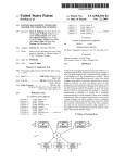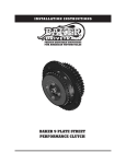
1
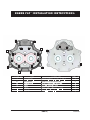
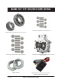
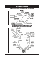
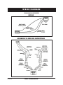
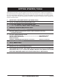
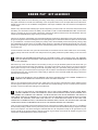
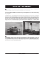
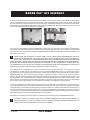
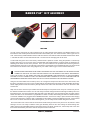
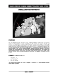
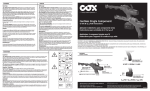
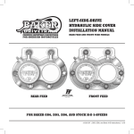
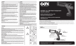
install ation instr uctions tm FEATURES OVERVIEW The BAKER ‘Factory 6 Fix’ was conceived as a response to the overwhelming call from the biker community for a solution to the 5th gear noise in the new factory 6 speeds standard in all bikes for the 2007 model year. Whereas some people out there will tell you that it is ‘normal’ or not that bad, we do not feel that way. Your bike is not some garage sale lawnmower, it should not sound like it is about to explode on it’s maiden voyage. Our ‘F6F’ kit uses the latest and greatest BAKER Diamond Cut Helical 5th Gear Pair to replace the stock straight cut spur gears. We utilize an aircraft aluminum billet bearing door that is then polished and show chrome plated. Not stopping with just a new bearing door, we took it a step farther by using heavy duty, steel cage (rather than the stock plastic cage) bearings in the trap door that are 28% wider than stock. We ditched the wimpy snap rings and replaced it with a 1/8” thick steel bearing retainer plate that is held on with 6 Grade 8, ¼-20 Bolts. What does all this work and new parts mean to you as the customer and your overall riding experience? The mainshaft will no longer want to walk through the case and push against the stock wimpy trap door set up, resulting in no more clutch lever movement with low rpm acceleration. You will no longer have a 5th gear whine that sounds like a broke down supercharger whining down the highway. FITMENT: 2006-2009 Dyna 2007-2009 Touring 2007-2009 Softail V6-031609 PAGE | OVERVIEW b a kEr F6F ™ install ation instr uctions: A A E B B E A F A D D C C F C C A A A A itEM location P/n dEscriPtion Quantity A 3AG1.500-12CL 5/16-18 x 1.5” 12 PT Bolts, Polished STS 8 B 2AL1.000-3SL 1/4-20 x 1.0” 12 PT, Polished STS 2 C 2AL1.250-12SL 1/4-20 x 1.25” 12 PT, Polished STS 4 D 26735 Dowel Pin, 3/16 Dia x .500” 2 E 147489 10-24 x .500” Hex Washer Head Bolt 2 F 16583-00 10mm Hollow Dowel Pin 2 PaGE 2 | V6-031609 b ak e r F6F ™ K it includ ed part s Detail BAKER Diamond Ground Helical Cut 5th Gear Pair Polished 12 pt ARP fasteners for the Trap Door Nylock Jam Nuts V6-031609 Polished 12 pt ARP fasteners for Side Cover Prepped & Assembled Chromed Billet Aluminum Trap Door Assembly BAKER Recal Box: Deutsch Connectors & 8” Leads for the factory wiring harness PAGE | included parts detail wiring dia g rams For 2006-2009 Dyna, 2007-2009 Softail, 2007 touring BEFORE AFTER INSTALLING THE BAKER RECAL BOX ACCORDING TO SUPPLIED INSTRUCTIONS PAGE | wiring diagrams V6-031609 wir ing dia gra ms for 2008-2009 touring BEFORE brown orange yellow AFTER INSTALLING THE BAKER RECAL BOX ACCORDING TO SUPPLIED INSTRUCTIONS BROWN WITH ORANGE STRIPE BROWN WITH ORANGE STRIPE YELLOW YELLOW V6-031609 PAGE | wiring diagrams ge tting start ed/TOOLS Disassembly and assembly of the entire gearset is not a job for the weekend warrior to attempt, the installation of the F6F kit should only be handled by experienced techs or the local mechanic of you choice. For installation of this kit, or any other drivetrain related project, a Factory Service Manual for your particular bike is a must have. Common hand tools, sockets, allen wrenches, snap ring pliers, screwdrivers, will suffice for a majority of the job, specialty tools required are listed out below. ★ Solder Gun, (For BAKER ReCal Box Wire Leads) ★ 13/16” 6pt Socket (Motor Sprocket Nut) ★ 1 3/16” 6pt Socket (Clutch Sprocket Nut) ★ 1 1/16” 6pt Socket (Tranny Shaft Nylock Nuts) ★ Mainshaft Bearing Race Service Tool ★ Primary Chain Locking Tool ★ Bearing Removal Hydraulic Press Tool (BAKER PN 483-6T) *** sold separately *** ★ 32 oz of Transmission Fluid Spectro: TRANSMISSION OIL.......................................................call baker for pn REDLINE: HEAVY SHOCKPROOF....................................................baker pn: lrl-56 HARLEY-Davidson: formula + transmission and primary lubricant.................harley pn: 99857-05 ★ 38 oz of Primary Fluid ★ ‘BLUE’ Thread Lock ★ ‘RED’ Thread Lock ★ Access To A 20 TON Hydraulic Press ★ customers installing the baker f6f on 2006 dyna need to separately purchase a h-d® p/n: 33409-06b, detent arm kit. this detent kit works with the provided baker f6f and the stock h-d® shift drum. PAGE | getting started/tools V6-031609 b a k e r F 6 F ™ kit assembly Whereas it may seem as we are skimming over many of the steps, your Factory service manual will lay out in detail the proper methods for removal and reassembly of the components listed out in the steps within these instructions. Softails, Dyna’s and FL’s are all different configurations and require a different order and method to accomplish the various steps. Similar to any other Drivetrain related project, the first steps that you want to take is to remove the seat and disconnect the battery. You will need to remove the battery and set aside in order to install the BAKER Recal Box at a later time. Now is a good time to get out a couple of drain pans and drain the primary fluid as well as the transmission fluid. For location of the applicable drain plugs, check your service manual. Next remove the bags, (if applicable), then the floorboards/pegs and the pipes. Remember to disconnect the O2 sensor plugs from the pipes so as to not damage them when pulling the pipes off. Unbolt the starter and pull it out and set aside on your workbench. Pull off the outer primary, the primary chain, clutch assembly and the inner primary. Having a drip pan underneath the primary when you are taking off the primay is a great idea as residual oil will get all over your lift or garage floor depending on your work environment. Pull the bearing race found on the mainshaft next with your bearing race service tool. Loosen the bolts on the side cover, pull it off and set aside, do not detach from the clutch cable as it is not necessary. Placing a shop towel under the side cover will prevent it from getting scratched up while working on the rest of the bike. REMOVE THE TRANSMISSION DIPSTICK AT THIS TIME AS WELL, YOU CAN NOT PULL THE GEARSET WITH THE DIPSTICK IN THE BIKE. IT WILL BREAK OFF IF YOU LEAVE IT IN THE BIKE WHEN ATTEMPTING TO PULL THE GEARSET. Remove the top cover and set aside, this is necessary so that you can pull the shifter pawl off of the drum when you remove the entire gearset and trap door assembly. According to the Factory service manual, you want to place the shifter pawl on the top cover mounting surface with the gasket acting as a ‘pad’ whilst pulling the gearset. Using a 1 1/16” 6 pt socket, you need to loosen the nylock jam nuts on both the countershaft and mainshaft before you remove the gearset from the case. A good trick is to stand with you right foot on the rear brake pedal while trying to loosen the jam nuts with a breaker bar. DO NOT USE AN IMPACT GUN TO REMOVE THE SHAFT JAM NUTS AS IT HAS A GREAT TENDENCY TO DAMAGE THE THREADS OF THE M/S & C/S THAT YOU NEED TO REUSE. Now you can unbolt the trap door from the case. Lightly tap on the end of the mainshaft with a rubber mallet to loosen the entire gearset and trap door from the case and the 6th main needle bearings. You do not need to loosen the drive sprocket or remove the 6th main bottle gear to install this kit. DO NOT HIT THE END OF THE MAINSHAFT WILL A BALL PEEN HAMMER, OR ANY OTHER METAL HEADED HAMMER. HITTING THE MAINSHAFT WITH A GREAT AMOUNT FORCE IN ANY MANNER, WITH ANY HAMMER WILL DAMAGE THE THREADS. YOU MUST REUSE YOUR STOCK MAINSHAFT AND WANT TO TAKE GREAT CARE NOT TO DAMAGE IT. IF YOU FEEL THAT YOU DO NEED TO USE A GREAT DEAL OF FORCE TO REMOVE THE GEARSET, STOP AND LOOK OVER ALL OF YOUR PREVIOUS STEPS AS YOU MAY HAVE FORGOTTEN TO REMOVE A BOLT, THE MAINSHAFT BEARING RACE, MOVED THE SHIFTER PAWL OR SOME OTHER SOLID OBJECT IS IMPEDING THE PATH OF THE GEARSET BEFORE YOU PROCEED. Once you have successfully removed the gearset from the case and have it sitting with the trap door on a workbench and the shafts pointing in the air, refer to your Factory service manual for the safe and efficient way to strip the assembly down to the trap door. You will be reusing the mainshaft and all of its components except for 5th gear. Refer to your service manual for the proper method to remove the snap ring and swap out the stock 5th straight cut gear on the mainshaft for the BAKER Diamond Ground Helical Gear. V6-031609 PAGE | assembly b a k er F 6 F ™ kit assembly TAKE CARE AS NOT OPEN THE SNAP RING OPEN MORE THAN YOU HAVE TO IN ORDER TO SLIP IT OVER THE SHAFT SPLINES. OVER EXPANDING THE SNAP RING WILL NEGATE IT’S ABILITY TO SQUEEZE PROPERLY ON THE SHAFT AND WILL REQUIRE THAT IT BE REPLACED. The directional teeth of the BAKER 5th Gear should be going in an opposite direction to the rest of the teeth that are part of the mainshaft. Also you will need to have the side of gear with the pockets in it for the dog clutch to be facing away from gears 1-4. Following the service manual, disassemble the countershaft down to 5th gear. You will then need to use a Bearing Removal Tool to ‘press’ the stock 5th gear off of the countershaft. BAKER designed and sells a tool just for this job. If you do nothave one, contact your BAKER sales technician because they are sold seperately. It is like anything in life, having the right tool for the job makes life itself easier and greatly reduces the risk of injury. Following the picture below place the 2 halves around the gear and bolt it together with the provided 5/16 Grade 8 bolts. You then, similar to the picture, need to press the gear off of the shaft. You must ensure that you have everything lined up completely vertical and parallel to the ram on the press. Getting the gear cocked or crooked on the shaft can and will result in both and shaft and gear damage. Any time that you are using a Hydraulic Press of any size, care needs to be taken to make sure that you are operating the tool in a safe manner and that the machine is in good working order. That you are using adequate and solid pieces of material to push on the countershaft with to prevent them from slipping out of the stack while under load. That you are using a solid base plate that securely fits on the crossbeams of the press. It is completely in your best interest and personal safety to be careful in your operation practices and general machine awareness. PAGE | assembly V6-031609 b a k e r F 6 F ™ kit assembly Once you have removed the stock gear from the countershaft, you are ready to press on the BAKER 5th Countergear. The gear orientates in the same manner with the smaller ‘snout’ of the gear butting up firmly against the 6th gear which is a part of the shaft. Flip the shaft and tool over and press the new BAKER Helical gear onto the shaft in the manner demonstrated in the figure below. Make sure to fully press the new BAKER 5th Helical gear against 6th gear. It is critical for the overall spacing of the gears down the countershaft. Once you have successfully pressed the BAKER 5th Counter gear onto the shaft you are ready to reassemble the countershaft. Carefully following the service manual, reassemble the gears back onto the countershaft, make sure that the gears are free of dirt and debris and that the needle bearings are well lubricated with transmission fluid before you put a gear on top of them. GREAT CARE AND ATTENTION TO DETAIL NEEDS TO BE TAKEN WHEN REASSEMBLING THE SPLIT SECURING SEGMENTS AND THE VARIOUS SPLINED THRUST WASHERS ONTO THE COUNTERSHAFT, WHILE THEY ARE EASIER TO USE THAN SNAP RINGS, THEY CAN BECOME EASILY DISLODGED FROM THEIR DESIGNED POSITION AND CAN BE VERY EASILY DAMAGED WHILE PRESSING THE COUNTERSHAFT BACK INTO THE DOOR AND WHEN TIGHTENING THE JAMNUTS TO THE TORQUE SPECS. USING A SMALL PIC OF SCREWDRIVER TO PUSH THE SPLIT RINGS INTO POSITION AROUND THE COUNTERSHAFT CAN HELP TO MAKE SURE THAT THEY ARE SECURLY IN POSITION AGAINST THE SHAFT. In an attempt as to not dislodge any of the thrust washers or split securing segments, do not tip over or lay the countershaft on it’s side until you have pressed it into the provided BAKER Bearing Door. The method and manner to press it back into the trap door follows the service manual directed method. Next the mainshaft is pressed into the BAKER Bearing Door. Take your time while pressing the mainshaft into place to make sure the gears are meshing together. With the 2 shafts completely assembled and pressed into the bearing door, bolt the bearing door into the case with the provided 5/16 -18 ARP Fasteners and tighten the provided BAKER Nylock Jam Nuts onto the shafts to 45-55 ft/lbs. Using the rear brake/ right foot technique is necessary to achieve the full torque values. When you have tightened the jam nuts, pull the trap door back out in preparation for assembly and installation of the shift system. You will be reusing the entire shift system except for the (2) 10-24 Bolts that hold the shift drum retaining plate to the door. During reassembly, use the provided 10-24 bolts to retain the shift drum plate. Refer to the manual for the proper order and manner to reassemble the shift system into the door. Make sure to double check that all of the gears spin in a free and smooth manner and use this time, once you have reassembled the entire gearset to check over everything so that it is free of dirt, debris and that all fasteners have been tightened down properly. Set aside the gearset and cover with a plastic bag so as too keep dirt and shop debris out of the gears. At this time you need to splice into the factory wire harness to be able plug in the provided BAKER Recal Box. Failure to install the recal box in the correct manner will cause your speedo to read incorrectly, your EFi system to not function properly causing the bike to run poorly and the 6th gear dash light will not work. V6-031609 PAGE | assembly b a k er F 6 F ™ kit assembly Speedometer Side VSS Side You will need to disconnect the wiring harness from the VSS (Vehicle Speed Sensor) and Neutral Switch on the transmission case and the pull the wire harness back into the battery box. You need to do this in order to gain room to work. Cut the factory installed sheath off of the VSS wires back to union with the starter and Neutral switch wires. About 7” total and set aside. You then will measure back 1.5” back from the VSS plug and cut the wires. Cut the white with green wire on the Factory harness before it splits into 2 wires. Using the provided 1” shrink wrap lengths, slide them on to the 3 wires of the provided Male and Female Deutsch Connector leads in preparation for soldering those leads into the factory harness. Once you have soldered in the provided leads and have gotten the Female Deutsch Connector on the VSS side of the harness, and the Male on the Speedometer side your wiring should be as listed out as denoted on the wiring diagram for your model of bike on pg’s 4 and 5 of these instructions. Patience and care need to be taken to ensure that the soldering of the wires is done correctly and that you have a good contact of the wires at the joints. Additionally that the layout of the wires follows the procedure laid previously in this document. Failure to do so correctly will not be known until the bike is all put together and the speedometer does not move when you go to leave the shop for the maiden voyage. Using the removed sheath from the factory wires, cut to length and wrap around the wires of the VSS sensor, from the factory plug back to the joint you just created with the Female Deutsch Connector leads. Reinstalling the factory sheath helps protects those wires that lay directly between the starter and transmission case from the heat of that environment. Wrap the rest of the wires that you installed with electrical tape to keep them bunch nicely out of harms way and for the abrasion resistance that it offers. You are now ready to feed the wiring harness back through the battery box to the transmission area. You need to feed the VSS plug back to the VSS sensor, the neutral plugs back into place and the starter feed down to the transmission in preparation for starter re-install, whilst leaving the male and female Deutsch Connectors available to be plugged into the BAKER ReCal Box. You then are ready to place the ReCal box hanging over the side of the frame, under the seat, in preparation for the maiden voyage and Calibration Process. Lay the ReCal Box in such a manner that when the bike is back together, you can safely access it while riding down the road Check the inside of the case as well as the 6th main needle bearings such that they are free or dirt, debris or metal shavings. You are now ready to slide the entire gear assembly back into the case reusing the stock bearing door gasket. Using the provided ARP Fasteners with ample amounts of ‘BLUE’ Thread Lock , bolt the trap door to the case in the order as directed by the service manual. Torque the bolts to 225 in-lbs. PAGE 10 | assembly V6-031609 Make sure you still have the shifter pawl out of the way when you slide the gearset back in the case to prevent damaging the pawl. At this time you should jack up the rear tire just enough to clear the ground so that you can spin the back tire and shift the transmission through all 6 gears. This is a preventive measure to make sure that everything was re-installed correctly, that all of the thrust washers and spilt rings are in their proper positions and that it shifts properly. If it performs satisfactorily, you can begin the reassembly process. If not, you need to pull the gearset and double check everything. If that still does not solve the matter that you are experiencing, feel free to call our tech line at 877.640.2004. When you have been able to dry shift it through all 6 gears you are ready to reassemble the rest of the bike. Loosen the clutch cable turnbuckle on the down tubes of the motorcycle at this time. Begin with putting the transmission side and top covers back on the case, follow the service manual torque specs and use ‘BLUE’ Thread Lock. Use the provided ¼20 ARP Fasteners to reattach the side cover. Look back to the bolt layout diagram to determine which length bolt goes where. Torque to 150 in-lbs. This is a great time to put fluid in the transmission as having the pipes back on the bike makes it much harder to get a funnel in the transmission. Fill to the Factory specified level. (32oz capacity) Using a main shaft bearing service tool, press the inner race back on the mainshaft, it should be .100”- .125” from the end of the 6th main when finally installed per the Factory service manual. Reinstall the inner primary, clutch assembly, chain tensioner , chain and motor sprocket. Refer to the factory manual for bolt torque sequence, Thread Lock strength callouts and the ‘trick’ to getting the chain tensioner fully compressed to be bolted back into the bike. Torque everything to factory values and reinstall the clutch keyway fitting, adjuster rod and snap ring. Replace the outer primary and torque with the factory diagram torque order. You can continue to replace all of the parts onto your bike in the reverse order that you took them off. Once you have gotten to the point of reconnecting the battery and replacing the seat and saddlebags (if applicable) you are ready to fill the primary with fluid and adjust the clutch. Remove the derby cover from the outer primary and using a funnel pour in 38 oz Primary Fluid. Being that the BAKER ‘Factory 6 Fix’ Kit did not touch the clutch, actuator rod or side cover you can simply follow the Factory Service Manual for clutch adjustment details. When you successfully reassembled your motorcycle, take the time to double check that you have replaced all of the parts and that none are left on the lift /garage floor, work bench etc. Take the time to double check the drain plugs are tight and to wipe down the bearing door , side cover and primary to make sure there are no leaks after the maiden voyage. When you take off for your test ride, ease into it and slowly accelerate through the gears to ensure that you reassembled the vehicle in a functional and safe manner, additionally to ensure that you can make sure all of the components are functioning in their designed manners. You are now ready to Calibrate your speedometer. Refer to the paperwork attached with the Recal Box for the details of box function. Follow someone in a car and double check that you are accurate at 50mph, 60mph and 70mph. Once you completed calibrating the speedo, you pull the side panels from your FL or Dyna, or the Seat from your Softail and tuck the BAKER Recal box out of harms way. V6-031609 PAGE 11| assembly ter ms SPECIAL ORDERS A minimum $500 deposit is required with all special orders. Special orders include unique case finishes, unique side door requests (i.e.; wrinkle black door or no logo). ALL OTHER ORDERS Orders can be pre-paid using VISA, Mastercard or American Express. Prices shown are F.O.B. Haslett, MI. BAKERTM provides free UPS ground shipping on all retail orders for complete transmissions or transmission kit. UPS air shipment is available upon request. Customer is responsible for air shipment premiums. LIMITED WARRANTY BAKERTM Inc. F6F is guaranteed to the original purchaser to be free of manufacturing defects in materials and workmanship for a period of 2 years from the date of purchase If the product is found by BAKERTM to be defective, such products will, at the option of BAKERTM, be replaced or repaired at cost to BAKERTM. In the event warranty service is required, the original purchaser must call or write BAKERTM immediately with the problem. If it is deemed necessary for BAKERTM to make an evaluation to determine whether the transmission assembly or transmission kit is defective, the entire transmission assembly, whether originally purchased as an assembly or kit, must be properly packaged and returned prepaid to BAKERTM with a copy of the original invoice of purchase. If after an evaluation has been made by BAKERTM and a defect in materials and/or workmanship is found, BAKERTM will, at BAKER’s option, repair or replace the defective part of the assembly. Warranty card must be returned within 45 days of purchase to be valid. ADDITIONAL WARRANTY PROVISIONS This limited warranty does not cover labor or other costs or expenses incidental to the repair and or replacement of BAKERTM products. This warranty does not apply if one or more of the following situations is judged by BAKERTM to be relevant: improper installation, accident, modification (including but not limited to use of unauthorized parts), racing, high performance application, mishandling, misapplication, neglect (including but not limited to improper maintenance), or improper repair. BAKERTM shall not be liable for any consequential or incidental damages arising out of or in connection with a BAKERTM transmission assembly, transmission kit, swingarm, fender, component or part. Consequential damages shall include without limitation, loss of use, income or profit, or losses sustained as the result of injury (including death) to any person or loss of or damage to property. BAKERTM transmissions, transmission kits, and Wide Tire Kits are designed exclusively for use in Harley-Davidson® motorcycles. BAKERTM shall have no warranty or liability obligation if a BAKERTM part is used in any other application. If it is determined that a BAKERTM transmission assembly has been disassembled during the warranty period for any reason, this limited warranty will no longer apply. PAGE 12 | TERMS V6-031609 discl aimer The words Harley, and H-D are registered trademarks and are for reference only. Use of H-D model designations and part numbers are for reference only. BAKER Drivetrain has no association with, and makes no claim against, these words, trademarks, or companies. It is the sole responsibility of the user to determine the suitability of this product for his or her use, and the user shall assume all legal, personal injury risk and liability and all other as well as all other obligations, duties and risks associated therewith. customer support For any installation or service questions, please contact our BAKER technical department toll free: 1-877-640-2004. V6-031609 PAGE 13 | DISCLAIMER