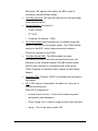
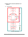
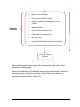
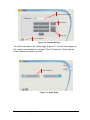
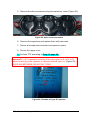
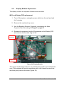
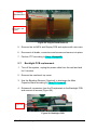
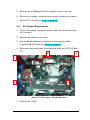
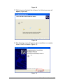
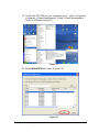
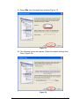
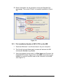
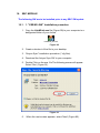
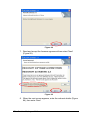
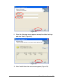
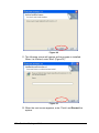
1
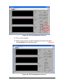
Service Manual
August 2010, Revision 03
Service Manual
August 2010, Revision 03
© 2007-2010 Radiancy Inc. All right reserved.
Mistral Service Manual, August 2010. Part Number: 2019890. Revision 03
Note: The information in this document is confidential and proprietary. It is provided to
customers and authorized representatives of Radiancy only. The content of this manual is
furnished for informational use only, is subject to change without notice and should not be
construed as a commitment by Radiancy Inc.
LHE is a registered trademark of Radiancy Inc. in the United States and/or in other countries.
The Quality Management System of Radiancy Ltd. complies with the Quality Management
Standard ISO 13485-2003.
Manufacturer: Radiancy (Israel) Ltd., 5 Hanagar St., P.O. Box 7329, Hod
Hasharon, 45240, Israel, Tel: 972-9-775-7500, Fax: 972-9-775-7511
www.radiancy.com
Authorized European Representative: Obelis S.A,, Av. de Tervuren
34 Bte .44, B-1040 Brussels, Belgium. Tel: 32 (0) 2 732 5954, Fax: 32
(0) 2 732 6003, GSM 07545 4660, e-mail: [email protected]
KEMA Notified Body.
Contact Information
Customer satisfaction is a Radiancy priority. To help us in providing you with
the best possible product and support, please send us your comments and
suggestions. Contact us at the addresses and telephone numbers below:
US
Radiancy Inc.
40 Ramland Road South, Suite 200
Orangeburg, NY 10962
USA
Toll Free: 888 661-2220
Tel: +1 845 398-1647
Fax: +1 845 398-1648
E-mail: [email protected]
ii
Israel
Radiancy (Israel) Ltd.
5 Hanagar St., P.O. Box 7329
Hod Hasharon, 45240
Israel
Tel: +972-9-775-7500
Fax: +972-9-775-7511
E-mail: [email protected]
Table of Contents
1. INTRODUCTION TO THE SYSTEM
1
2. SYSTEM DESCRIPTION
2
2.1. SYSTEM COMPONENTS AND CONTROLS:............................................. 2
2.2. TECHNICAL INFORMATION .................................................................. 6
2.3. MAJOR PRECAUTIONS & W ARNINGS ................................................... 7
2.4. LABELS ............................................................................................. 9
2.5. INTERNATIONAL STANDARDS COMPLIANCE.......................................... 12
3. INITIAL SET UP
13
3.1. UNPACKING MISTRAL ......................................................................... 13
3.2. INSTALLATION .................................................................................... 14
3.3. MISTRAL BLOCK DIAGRAM .......................................................... 16
4. SYSTEM OVERVIEW
17
4.1. MODULE OVERVIEW AND INITIAL COMMENTS ...................................... 17
4.2. MODULES DESCRIPTION AND ROLE .................................................... 20
5. MISTRAL STARTUP SEQUENCE (EMERGENCY NOT ENABLED)
22
5.1. SYSTEM STARTUP ............................................................................. 22
6. SCREEN CALIBRATION
25
7. TECHNICAL INFORMATION
26
8. MODULES REPLACEMENT
26
8.1. HP REPLACEMENT ............................................................................ 26
8.2. AREA ADAPTOR PLACEMENT .............................................................. 27
8.3. FUSE REPLACEMENT ......................................................................... 28
9. REPAIR INSTRUCTIONS
29
9.1. MAIN BOARD REPLACEMENT .............................................................. 29
9.2. SPLITTER REPLACEMENT ................................................................... 30
9.3. 12V LVPS REPLACEMENT ................................................................. 31
9.4. 24 V LVPS REPLACEMENT) ............................................................... 32
9.5. CAPACITOR REPLACEMENT ................................................................ 33
9.6. DISPLAY MODULE REPLACEMET ......................................................... 35
iii
9.7. BACKLIGHT PCB REPLACEMENT ......................................................... 36
9.8. PS CHARGER REPLACEMENT ............................................................. 37
10. MACHINE FTP
40
10.1. SOFTWARE INSTALLATION / UPGRADE............................................... 40
10.2. BLEEDING THE CAPACITORS............................................................. 40
10.3. HW "HOT" TESTS ............................................................................ 42
10.4. FINAL TEST PROCEDURE ................................................................. 43
11. HW TESTS
47
11.1. GENERAL TEST ............................................................................... 47
11.2. MANIFOLD & BLOWER FUNCTIONAL TEST.......................................... 47
11.3. BLOWER CALIBRATION ..................................................................... 47
11.4. SAFETY TESTS ................................................................................ 53
12. ENERGY TESTS
54
12.1. CONFIGURE ENERGY SETTINGS: ...................................................... 55
13. TROUBLESHOOTING
57
14. MISTRAL SERVICE
58
15. APPENDIX A
59
15.1. MCU MODULE................................................................................. 59
15.2. "FDT" INSTALLATION PROCEDURE (HANDLES *.MOT FILES) ................ 59
15.3. FILE INSTALLATION/UPDATE OF MCU CPU ON THE MB..................... 70
15.4. TSI AIR FLOW METER SW INSTALLATION ................................ 75
16. SBC MODULE
77
16.1."USB M LINK" INSTALLATION PROCEDURE ........................................ 77
16.2. "TERATERM" INSTALLATION PROCEDURE................................. 81
16.3. INSTALLATION OF THE SPLASHIMAGEUPDATER_0_4_59_7................ 83
16.4. SBC SOFTWARE UPDATE PROCEDURE.............................................. 83
17. APPENDIX B
93
17.1. MISTRAL ALPHA TYPE .................................................................... 93
17.2. MAIN DIFFERENCES BETWEEN THE ALPHA AND CURRENT UNITS ........ 94
18. MODULES REPLACEMENTS (UNIQUE TO ALPHA TYPE UNITS) 97
18.1. SPLITTER REPLACEMENT ................................................................. 97
iv
18.2. 12V LVPS REPLACEMENT ............................................................... 98
18.3. 24 V LVPS REPLACEMENT\EXTERNAL BLOWER CONTROLLE ............. 98
18.4. PS CHARGER REPLACEMENT ................................................................. 99
v
LIST OF FIGURES
Figure 1: Mistral Main System......................................................................2
Figure 2: Front Panel ...................................................................................3
Figure 3: Back Panel....................................................................................3
Figure 4: Right Side Panel ...........................................................................4
Figure 5: Handpiece.....................................................................................4
Figure 6: Footswitch.....................................................................................5
Figure 7: Handpiece Connection ................................................................15
Figure 8: Top View .....................................................................................18
Figure 9: Second layer (Charger); front view ..............................................19
Figure 10: Password Entry .........................................................................24
Figure 11: Home Page ...............................................................................24
Figure 12: Settings Page............................................................................25
Figure 13: HP Replacement .......................................................................26
Figure 16: Fuse Location............................................................................28
Figure 17: Main Board................................................................................29
Figure 18: Splitter.......................................................................................30
Figure 19: 12V LVPS .................................................................................31
Figure 20: 24 V LVPS ................................................................................32
Figure 21: Capacitor...................................................................................33
Figure 22: Allen screw placement ..............................................................34
Figure 23: Example of Type B Capacitor....................................................34
Figure 24: Display Module..........................................................................35
Figure 25: Copper Braid Removal ..............................................................36
Figure 26: Backlight PCB ...........................................................................36
Remove the old ..................................................................................37
Figure 28: PS Charger – Studs & Screws ..................................................38
Figure 29: PS Charger – Ties & Screws.....................................................38
Figure 30: PS Charger – Remaining Connections......................................39
Figure 32: Screw Placement ......................................................................41
Figure 33: Bleeding Resistor and Capacitor ...............................................41
Figure 34: SW Version ...............................................................................43
Figure 35: Login Screen.............................................................................43
Figure 36: Settings .....................................................................................44
Figure 37: Tech Info ...................................................................................44
Figure 38: Tech Info Password Entry .........................................................45
Figure 39: Internal SW Version ..................................................................45
Figure 39: Calibration.................................................................................48
Figure 40: Calilbration 2 .............................................................................49
Figure 41: Calibration Trimmer...................................................................49
Figure 42: Air Flow .....................................................................................50
Figure 43: Air Flow Connection ..................................................................50
Figure 44: TSI Flow Adjustment Screen 1 ..................................................51
Figure 45: TSI Flow Adjustment Screen 2 ..................................................52
Figure 46: TSI Flow Adjustment Screen 3 ..................................................52
Figure 47: Dip Switches' Final Position ......................................................53
Figure 48: Password Entry .........................................................................54
vi
Figure 49: Select Application Screen .........................................................54
Figure 50: Select Pulse Level Screen.........................................................55
Figure 51: Confirm Selection......................................................................55
Figure 52: Basic Adaptor Window ..............................................................56
Figure 53:...................................................................................................59
Figure 54:...................................................................................................59
Figure 55:...................................................................................................60
Figure 56:...................................................................................................60
Figure 57:...................................................................................................61
Figure 58:...................................................................................................61
Figure 59:...................................................................................................62
Figure 60....................................................................................................62
Figure 61....................................................................................................63
Figure 62:...................................................................................................63
Figure 63:...................................................................................................64
Figure 64:...................................................................................................64
Figure 65....................................................................................................65
Figure 66:...................................................................................................65
Figure 67:...................................................................................................66
Figure 68:...................................................................................................67
Figure 69....................................................................................................67
Figure 70:...................................................................................................67
Figure 71:...................................................................................................68
Figure 72....................................................................................................68
Figure 73....................................................................................................69
Figure 74....................................................................................................69
Figure 75:...................................................................................................70
Figure 76: E8 Emulator ..............................................................................71
Figure 77: MB Connection..........................................................................71
Figure 78....................................................................................................71
Figure 79:...................................................................................................72
Figure 80:...................................................................................................72
Figure 81:...................................................................................................73
Figure 82:...................................................................................................73
Figure 83:...................................................................................................74
Figure 84:...................................................................................................74
Figure 85....................................................................................................75
Figure 86:...................................................................................................75
Figure 87:...................................................................................................76
Figure 88:...................................................................................................76
Figure 89....................................................................................................76
Figure 90:...................................................................................................77
Figure 91:...................................................................................................77
Figure 92:...................................................................................................78
Figure 93:...................................................................................................78
Figure 94:...................................................................................................79
Figure 95:...................................................................................................79
vii
Figure 96:...................................................................................................80
Figure 97:...................................................................................................80
Figure 98:...................................................................................................81
Figure 99:...................................................................................................81
Figure 100:.................................................................................................82
Figure 101:.................................................................................................82
Figure 102..................................................................................................82
Figure 103:.................................................................................................83
Figure 104:.................................................................................................84
Figure 105:.................................................................................................84
Figure 106:.................................................................................................84
Figure 107:.................................................................................................85
Figure 108..................................................................................................85
Figure 109..................................................................................................85
Figure 110:.................................................................................................86
Figure 111:.................................................................................................86
Figure 112:.................................................................................................87
Figure 113:.................................................................................................87
Figure 114:.................................................................................................88
Figure 115:.................................................................................................88
Figure 116..................................................................................................89
Figure 117:.................................................................................................89
Figure 118:.................................................................................................90
Figure 119:.................................................................................................90
Figure 120..................................................................................................91
Figure 121..................................................................................................91
Figure 122:.................................................................................................92
Figure 123:.................................................................................................92
Figure 124..................................................................................................94
Figure 125..................................................................................................95
Figure 126..................................................................................................95
Figure 127..................................................................................................96
Figure 128..................................................................................................97
Figure 129..................................................................................................98
Figure 130..................................................................................................99
Figure 131................................................................................................100
Figure 132................................................................................................101
List of Tables
Table 1: Handpiece Color Identification........................................................5
Table 2: Technical Specifications .................................................................6
Table 3: International Standards Labels .......................................................9
Table 4: Additional Labels ..........................................................................11
viii
1. INTRODUCTION TO THE SYSTEM
Mistral is a Light and Heat Energy (LHE®) based multi-application device for
the treatment of:
•
Hair Removal (HR)
•
Skin Photo Rejuvenation (SPR) (skin texture, fine lines)
•
Pigmented lesions (sun spots, age spots)
•
Vascular lesions (telangiectasias, spider veins)
•
Acne Clearance (AC)
•
Psoriasis Care (PSOR)
•
Skin Tightening (ST)
Mistral consists of a console, a Footswitch, and up to 7 interchangeable
Handpieces. Each Handpiece contains a pulse switch, a ready indicator light
and an application specific lamp. The Handpiece is held by the operator and
placed directly upon the treatment area. In this manual, the term operator
applies to all qualified personnel trained to operate the Mistral system.
Important Note – Please check which version/type of Mistral you are
servicing and refer to relevant sections in this Service Manual.
Refer to Appendix A (Alpha Units) to determine the type you are
currentley servicing
Mistral Service Manual
1
2. SYSTEM DESCRIPTION
This chapter provides a detailed description of the Mistral system; its main
components, controls, and technical specifications. Please review this
material to familiarize yourself with the controls, ports and connectors as
well as the consumable items used during treatment.
2.1.
System Components and Controls:
The Mistral system consists of the following main components (Error!
Reference source not found.):
•
System console (main unit)
•
Interchangeable handpieces
•
Footswitch
Handpieces
Console
Figure 1: Mistral Main System
2
Revision 03, August 2010
SYSTEM DESCRIPTION
2.1.1. Main Unit (System Console)
The main unit controls the operation of the entire system.
Front Panel:
•
•
•
•
Computer Interface / LCD Touch Screen
USB Ports
On/Off Switch
Emergency Stop Switch
Emergency Stop Button
LCD Touchscreen
USB Ports
Power Switch
Figure 2: Front Panel
Back Panel:
•
•
•
•
•
•
•
Power inlet
Main power switch
Fuse drawer
Handpiece cradle
Footswith port
System fan
Air exhaust port
System Fan
Handpiece Cradle
Main Power Switch
Air Exhaust Port
Fuse Drawer
Power Inlet
Figure 3: Back Panel
Mistral Service Manual
3
SYSTEM DESCRIPTION
Right Side Panel:
•
Handpiece power and air connections.
Connected Handpiece
Handpiece Connections
Figure 4: Right Side Panel
2.1.2. Handpieces
The Handpieces are connected to the main unit by a spiral cable containing
electrical wiring and an air suction hose. Each Handpiece consists of an
application specific lamp, pulse switch and pulse counter. When not in use,
the Handpiece should be stored in its cradle on the right side of the main
unit. The main unit will automatically detect the type of handpieces attached
to the unit and configure itself to conform to the attached handpiececes.
Switch
Warning: Always make sure the handpiece is secure.Pulse
Do not
drop.
This may cause damage to the lamp and handpiece.
Green Ready
Indicator Lights
Pulse Switch
LHE Lamp
Figure 5: Handpiece
4
Revision 03, August 2010
SYSTEM DESCRIPTION
Each handpiece is color coded for easy identifications.
Please refer to Table 1: Handpiece Color Identification .
Table 1: Handpiece Color Identification
Handpiece
Color
Hair Removal
Hair Removal V-VI
Hair Removal (XL Spot Size)
Hair Removal V-VI (XL Spot Size)
Skin Photorejuvenation
Acne Clearance
Psoriasis Care
Skin Tightening
When handpieces are not in use or attached to the device,store them in
their cases to prevent damage.
2.1.3. Footswitch
The footswitch arrives connected to the main unit. The system will emit a
pulse only if the footswitch and handpiece buttons are pressed
simoultaeneously.
Figure 6: Footswitch
Mistral Service Manual
5
SYSTEM DESCRIPTION
2.2.
Technical Information
Table 2: Technical Specifications
Technical Specifications
Light Source
Light & Heat Energy (LHE)
Wavelength Range
Hair Removal
400-1200 nm
Hair Removal V-VI (optional)
550-1200 nm
Skin Photo Rejuvenation
400-1200 nm
Acne Clearance (optional)
430-1100 nm
Psoriasis Care (optional)
350-1100 nm
Skin Tightening (optional)
780-1800 nm
Fluence
4-15 J/cm
Pulse Duration
Up to 80 ms
2
Spot Size
Basic
25 x 50 mm
Adaptor Sizes
13 x 50 mm; 13 x 35 mm; 13 x 12 mm
XL HR (optional)
35 x 50 mm
Pulse Generation Method
Capacitor bank electrical discharge switch
Physical Dimensions
40x47x32 cm (w/d/h): 15.8x18.5x12.6 in. (w/d/h)
Weight
16.8 kg./37 lbs.
Electrical Requirements
Single phase 100-120 VAC ±10%, 10A, 50-60 Hz
Single phase 220-240 VAC ±10%, 8A, 50-60 Hz
Operation Conditions
Temperature
5º-30º C
Humidity
30%-80% RH
Transport & Storage
Temperature
-20º- 80º C
Humidity
0%-95% RH; 0.1-1.5 atm.
6
Revision 03, August 2010
SYSTEM DESCRIPTION
2.2.1. Safety Features
Many of the Mistral features were built-in to help insure the safety of the
user and patient. The following are a few examples:
•
“Ready” indicator lights on the console and handpiece advise the
user when the system is charging or ready to emit a pulse.
•
Emergency Stop Button
•
The Footswitch prevents accidental pulses.
•
An internal and independent safety electronic circuit shuts down
pulse flashing ability in the event of a disabled blower.
•
Major Precautions & Warnings
2.3.
Major Precautions & Warnings
2.3.1. Precautions
•
Verify that Mistral's nominal voltage (see label at the bottom of the
system console) conforms to the electrical voltage of your electrical
outlet. Make sure that the electrical outlet has proper grounding.
•
Do not open Mistral’s outer case as dangerous voltages are present
inside the system. Only Radiancy certified personnel are authorized
to perform service within the protective covers of Mistral.
•
To perform routine maintenance always shut down the system,
disconnect power and wait a minimum of 5 minutes. Performing
maintenance procedures while the system is connected, or less than
5 minutes from disconnection may be hazardous to the operator and
destructive to the system.
•
Never use any flammable substance such as acetone or alcohol on
the skin prior to treatment.
•
Never use flammable substances or harsh chemicals to clean or
disinfect any part of the Mistral system.
Mistral Service Manual
7
SYSTEM DESCRIPTION
•
Always make sure to completely lift the Handpiece off the patient’s
skin between pulses in order to avoid excessive heating of the
handpiece or skin.
•
When the Handpiece is replaced, repeat testing procedures for each
patient during the first 500 pulses.
2.3.2. Warnings
8
•
Verify that all safety measures are working properly to ensure proper
safety.
•
Delivering excessive energy to the treatment site may cause thermal
damage to the skin, resulting in burns, crusting, or abnormal
pigmentation.
•
As a safety precaution, always have a first aid kit equipped to treat
burns at your disposal.
•
Operator should wear safety goggles when operating the device.
•
Although Mistral is considered an “eye-safe” device when operated
according to instructions, supplying patients with protective eyewear
during facial treatment will provide extra protection against
discomfort from light exposure.
•
Never look directly at the light coming from the handpiece as this
may cause temporary eye discomfort.
•
Looking away during the flash will further prevent discomfort.
•
Never allow the Handpiece to emit a pulse into ‘free space’. Always
make sure that the Handpiece is pointed at and in full contact with
the skin during treatment.
•
Even when the Energy level on touch screen is set at “0”, the system
can still trigger a pulse. Therefore be aware of the position of the
Handpiece at all times to avoid accidental flashing.
Revision 03, August 2010
SYSTEM DESCRIPTION
•
Always remain in visual contact with the computer screen to ensure
that the established energy is the correct "working energy" setting.
•
Pigmented moles and beauty spots and any suspicious (abnormal)
pigmented lesion should be covered with a non-flammable white
sticker.
2.4.
Labels
This section describes the labels affixed to Mistral. It is recommended that
users review the meaning of these labels for everyday use and in case any
details are needed for service.
The table below briefly reviews a number of the internationally recognized
symbols that are found on the Mistral main unit and its external package.
Table 3: International Standards Labels
Symbol
Meaning
Comments
Attention, consult
accompanying documents
before use
Attention, consult
accompanying documents
before use
Manufacturer
Authorized representitive in
the European community
Degree of protection against
electric shock: Type BF
applied part
Mistral Service Manual
9
SYSTEM DESCRIPTION
Protect the environment by
not disposing of this product
with household Waste
(2002/96/EC). Check your
local authority for recycling
advice and facilities (Europe
only).
CE mark represents the
compliance to the European
Medical Device Directive
93/42/EEC, Class IIa device.
The number (0344) is of the
notifying body, KEMA Notified
Body.
The C-Tick mark represents
compliance to Australian
EMC Regulations.
Voltage sticker
10
Revision 03, August 2010
Appears on outer package
SYSTEM DESCRIPTION
Additional stickers found on the main unit and the handpieces include serial
numbers of system parts and usage warnings.
Table 4: Additional Labels
Label
Location and Comments
Located on the back of the system this label
includes manufacturer details, voltage
information, and the system’s serial number.
Located on Mistral Handpieces
HR Handpieces:
Basic and optional XL
HR V-VI Handpiece (optional):
Basic and XL
SPR Handpiece
AC Handpiece (optional)
PSOR Handpiece (optional)
On rear panel, above power inlet. On 100120V systems, and on 220-240V systems,
respectively.
On rear panel.
This warning appears on all handpiecess, next
to opening.
Mistral Service Manual
11
SYSTEM DESCRIPTION
2.5.
International Standards Compliance
The Mistral complies with the following international standards and
directives:
EMC Standards:
IEC 60601-1-2:2001 + A1:2004
Clause 36.201 (Emission);
Clause 36.202 (Immunity);
Harmonized Standards:
Medical Electrical Equipment – Part 1:
General Requirements for Safety:
IEC60601-1:1988 + A1:1991 + A2: 1995
EU Directives:
- Low Voltage Directive 2006/95/EC
- Electromagnetic Compatibility Directive
2004/108/EC
- Medical Device Directive 93/42/EEC –
Class IIa device marked as CE 0344 of the KEMA Notified Body
(only for the Acne Clearance and Psoriasis Care applications)
12
Revision 03, August 2010
3. INITIAL SET UP
3.1.
Unpacking Mistral
The Mistral system is supplied with the following components:
•
Main Unit (console)
•
1 HR Standard Handpiece
•
1 SR Standard Handpiece
•
Optional Handpieces
•
ST Handpiece
•
AC Handpiece
•
PSOR Handpiece
•
HR XL Handpiece
•
HR Sensitive Handpiece
•
HR Sensitive XL Handpiece
•
Client Safety Goggles
•
3 Area Adaptors
•
2 Packs of Hygienic Rings (10 hygienic rings per pack)
•
Footswitch
•
Power Cable
•
User Manual
•
2 Fuses
•
Treatment Coat
•
Touch Screen Stylus
•
Electrical Requirements
Before unpacking Mistral, make sure the work site meets the following
electrical requirements. Mistral requires a separate single phase supply line
with nominal voltage (according to the local line voltage):
13
•
Single phase 100-120 VAC ±10%, 25A, 50-60 Hz; or
•
Single phase 220-240 VAC ±10%, 16A, 50-60 Hz
Revision B, May 2008
Mistral is grounded via the grounding conductor in the power cable that is
plugged into the wall power outlet. Good grounding is essential for safe
operation of the device.
It is recommended that the system’s power cable not be placed on the same
circuit as devices with heavy variable loads, such as air conditioning units.
The fuses located within the unit are rated:
•
5x20T 125V 10A for 100-120VAC
•
5X20T 250V 6.3A for 220-240 VAC.
Be sure to use the appropriate fuse for your region's electrical requirements.
When a fault in the system occurs, the fuse will burn out and the system will
not run.
3.2.
Installation
Mistral is designed for easy installation and does not require any site
preparation. Installation is carried out as follows:
•
Unpack the system and place it in a designated location. It
should be placed on a flat, stable surface, such as table,
counter or sturdy cart.
•
Verify that the system is intact and that all its components
are present.
•
Verify that the nominal voltage, recorded on the underside of
the unit, conforms to the electrical voltage of your country
(100-120V/220-240V).
3.2.1. Handpiece Connection
If necessary, connect the Handpiece according to the following instructions
(Figure 7):
1. Align the Handpiece power and air connectors with its power outlet
and air suction inlet. Use the metal prongs as a guide.
2. Snap into place.
14
Revision 03, August 2010
Figure 7: Handpiece Connection
To remove handpiece:
1. Push button on back of connector
2. Gently pull and pop out connection.
Note: Turn the system off when replacing or exchanging handpieces.
After the handpiece/s are connected:
1. Plug the system into a designated electrical outlet.
2. Test the system for proper operation.
Again, always make sure the handpiece is secure. Do not drop. This may
cause damage to the lamp and handpiece.
Mistral Service Manual
15
3.3.
MISTRAL BLOCK DIAGRAM
Diagram 1: Mistral Block
16
Revision 03, August 2010
4. SYSTEM OVERVIEW
The Mistral is built on a computer platform and is comprised of HW modules
as well as Software enviorment.
The SW enviorment requires (in general) a soft start up since it needs to be
uploaded in a well determined sequence.that is why the method of feeding
the Main AC to the platform and another push button for soft start up is
present in computers and specifically incoporated in the mistral.
4.1.
Module Overview and Initial Comments
The following pictures will illustrate the positioning of various modules within
the Mistral.
Attention!
For SW upgrade Please refer to Appendix A For further details
Mistral Service Manual
17
Line
Filter
12Vdc
PS
24Vdc
PS
Blower
Controller
Capacitor
Bank
DC
Blower
AC/DC
Splitter
HV Charger
See below
Main
Board
Figure 8: Top View
18
Revision 03, August 2010
Capacitor
Bank
12V LVPS
HV
Charger
DC
Blower
Figure 9: Second layer (Charger); front view
Mistral Service Manual
19
4.2.
Modules Description and Role
•
12v DC Power Supply: Receives 115-230VAC and outputs 2
Voltages: 5VDC and 12VDC.
These Voltages are supplied to various points inside the
machine, mostly to sub-units such as CPU and Backlight
illumination Panel and for "soft start" of the Unit.
•
24v DC PS: Supplies 24 VDC to the blower controller for
blower operation. (Doesn’t Exsist in Alpha type units)
•
PS Splitter: Receives 115-230VAC from the MB and splits it
into 2 separate major entities: The Blower and the Capacitor
Charging PS. Its main goal is to shut down the Voltage to the
Charger and Blower when System enters STBY to lower the
current consumption while on STBY.
•
Capacitor Charging PS: Receives 115-230VAC from the
Splitter and acts as a current source to charge the capacitors
via the MB.
•
Line Filter: Screens out noise from the outer AC network.
•
Pulsed Capacitors: The Energy Storage Pack is comprised
of 3 Capacitors connected individualy to the MB. It is
charged by the PS Charger via the MB.
•
Emergency Button: Connected to the MB, it shuts down the
pulse generating mechanism as well as the blower when
activated (pressed).
•
Blower Unit +Controller: Pulls air from the outside through
the Lamps into the HP to cool the HP and LUA. It is fed from
the PS Splitter with 115-230VAC. (In Alpha type machines
the contoller and blower are embedded together and the
Blower can operate on AC)
•
Tacho Unit: A tacho generator is a precision generator used
to sense the mechanical speed of rotation of a motor, hence
20
Revision 03, August 2010
the blower.The signal is then fed to the MB in order to
accurately maintain Blower speed .
•
Two way manifold: This unit will direct the air flow according
to the operational HP
•
•
Display Module : Consists of –
o
Touch Screen
o
TFT LCD
o
Computer On Module : COM
The COM module communicates on a constatnt basis with
the MCU and acts as the system master. The COM initiates
queries to the MCU, which determines which status or
Events are reported to the COM.
•
The Main Board (MB): The MB includes the major
processing unit (MCU) and sub-modules that monitor the
behaviour of the complete system.The MB communicates
with all other modules on a constant basis, such as the
COM (Computer On Module) which resides on the Display
Module.
•
Backlight PCB: Provides 12VDC to illuminate the backlight of
the display
•
HP: 2 HPs can be connected to the base unit. Only one is
operational during use.
Each HP is comprised of :
o
Internal Pulse Counter – Counts the number of pulses
delivered by that handpiece
o
Pulse Trigger Unit – Helps to trigger a pulse from the lamp
o
Lamp – The "Load" which emits LHE.
Mistral Service Manual
21
5. MISTRAL STARTUP SEQUENCE (EMERGENCY NOT
ENABLED)
5.1.
System Startup
Main AC SW
turn on
Line Filter
STBY
Mode
DCPS & SPLITTER
Receives AC
DCPS Yields
12V;5V
Splitter splits AC
to 24V PS &
Charger
2 Green Leds on MB
are Lit (D18,D9)
Soft Start Button is
pressed
12v,5v are supplied to MB
(Additional Led D8 Lits)
Operating
Mode
MCU Wakes up and
creates "self hold"
Flow Chart 1: Mistral Startup A
22
Revision B, May 2008
Software
Checklist
•
Buzzer Sound Release
•
Comm check with PS Charger
•
Determine deafault Charging value of PS
Charger
•
Manifold Check
•
ID of current connected Hp'es
•
Data Read of connected Hp
•
Blink Hp Leds
•
Initiating COM Module start and comm check
LOG ON Screan
Appears
Flow Chart 2: Mistral Startup B
After inititating start-up,the system will automatically begin with a short
introductory loading page.
When the introduction is finished the user will be automatically directed to
the logon screen. Using the numbers on the LCD screen, enter your
password and press enter. (Figure 10)
Mistral Service Manual
23
Enter Password Here
Backspace
Enter Key
Turn Off System
Figure 10: Password Entry
You will be directed to the Home Page (Figure 11). On the home page you
will usually a,as atechnitian, navigate "Direct Treatment". Gently tap the
screen where you wish to go next.
Enter Password
Figure 11: Home Page
24
Revision 03, August 2010
Settings (Figure 12) – It is recommended to set the language preference
and system parameters upon first startup.
Figure 12: Settings Page
6. SCREEN CALIBRATION
Screen Calibration should be performed once every 6 months.
1. Carefully press or touch stylus on center point of target. Using the
stylus for calibration is highly recommended.
2. Hold in place until target moves.
3. Follow the target around the screen until calibration is complete.
4. After calibration, tap the screen once to save data or wait 30
seconds to keep old data. You will be automatically directed to the
settings page.
Mistral Service Manual
25
7. TECHNICAL INFORMATION
This section is password protected and only accessible by a certified
technician.
Once your settings have been entered, they will be automatically saved and
available the next time you use the system. Select "Exit" to return to the
home page.
8. MODULES REPLACEMENT
8.1.
HP Replacement
Note: Turn the system off before replacing or exchanging handpieces.
The handpiece must be replaced every 50,000 pulses. Remove the
handpiece from the system and return it to your Radiancy representitive for
a replacement.
Figure 13: HP Replacement
To remove handpiece:
1. Push button on back of connector
2. Gently pull and pop out connection.
3. The Area Adaptors are used when treating different size and shape
areas. For hygienic reasons, clean the area adaptor between each
patient with a soft, damp cloth, as you would the handpiece.
26
Revision B, May 2008
8.2.
Area Adaptor Placement
Area adaptors come in 4 sizes (Figure 14) to help pinpoint treatment areas
and deliver more efficient treatments without affecting the surrounding skin.
Figure 14: Mistral Adaptor Sizes
Attaching the Area Adaptor:
Hold the adaptor in one hand and the handpiece in the other. Place the
adaptor on the handpiece as shown in Figure 15. Aline the two tabs with
the openings on the small ends of light unit. Gently press until you hear
a clicking sound ans adaptor is firmly in place.
Removing the Area Adaptor:
Hold the adaptor in one hand and the handpiece in the other and gently
pull off the adaptor
Figure 15: Area Adaptor Replacement
Mistral Service Manual
27
8.3.
Fuse Replacement
To replace the fuse and restore the energy after a fuse is blown, turn off the
unit and disconnect the system from the electrical outlet. Wait 5 minutes.
Pull out the fuse drawer located in the back panel. Replace the fuse and
push the drawer back into position.
Fuse panel
Power Cord Inlet
Figure 16: Fuse Location
28
Revision 03, August 2010
9. REPAIR INSTRUCTIONS
9.1.
Main Board Replacement
To replace the Main Board of the Mistral, perform the following:
1. Turn off the system, unplug the power cable from the wall and wait
for 5 minutes.
2. Remove the machine's top cover.
3. Use the Bleeding Resistor (Supplied) to discharge Main Capacitor
Bank according to Parag 10.1, page 41
4. Release all connectors to the MB
5. Remove the allen screws securing the MB to the chassis (Figure 17).
Figure 17: Main Board
6. Remove the old MB and replace it with a new one
7. Return all screws and connectors and secure in place.
8. Perform FTP according to Parg. 10 page 40.
9.2.
Splitter Replacement
1. Turn off the system, unplug the power cable from the wall and wait
for 5 minutes.
2. Remove the machine's top cover.
3. Use the Bleeding Resistor (Supplied) to discharge Main Capacitor
Bank according to Parag 10.1 page 41.
4. Disassemble the 12vDc PS and its connectors and Studs.Refer to
paragraph 9.3, page 29
5. Release all connectors to the Splitter
6. Remove allen screws securing the Splitter to the chassis (Figure
18).
Line Filter
?????/
AC/DC
Splitter
Figure 18: Splitter
30
Revision 03, August 2010
7. Remove the old splitter and replace it with a new one
8. Return all screws and connectors and secure in place.
9. Reassemble the 12vDc PS and its connectors and studs.Refer to
Paragraph 9.3, page 29.
10. Perform FTP according to Paragraph 10, page 40.
9.3.
12V LVPS Replacement
1. Turn off the system, unplug the power cable from the wall and
wait for 5 minutes.
2. Remove the machine's top cover.
3. Use the Bleeding Resistor (supplied) to discharge the Main
Capacitor Bank according to Parag 10.1 page 41.
4. Release all connectors to the 12V LVPS
5. Remove the allen screws securing the 12V LVPS to the chassis
(Figure 19)
Figure 19: 12V LVPS
Mistral Service Manual
31
6. Remove the old PS and replace it with a new one.
7. Return all screws and connectors and secure in place.
8. Perform FTP according to Parg. 10 page 40.
9.4.
24 V LVPS replacement)
1. Turn off the system, unplug the power cable from the wall and wait
for 5 minutes.
2. Remove the machine's top cover.
3. Use the Bleeding Resistor (Supplied) to discharge Main Capacitor
Bank according to Parag 10.1 page 41.
4. Release all connectors to the 24 V LVPS
5. Remove the allen screws securing the 24 V LVPS to the ramp
(Figure 20).
Figure 20: 24 V LVPS
32
Revision 03, August 2010
6. Remove the old 24 V LVPS and replace it with a new one.
7. Return all screws and connectors and secure in place.
8. Perform FTP according to Parg. 10 page 40.
9.5.
Capacitor Replacement
1. Turn off the system, unplug the power cable from the wall and wait
for 5 minutes.
2. Remove the machine's top cover.
3. Use the Bleeding Resistor (Supplied) to discharge the Main
Capacitor Bank according to Parag 10.1 page 41.
4. Release all connectors to the MB (Figure 21).
Connectors
Figure 21: Capacitor
Mistral Service Manual
33
5. Remove the allen screws securing the capacitors' cover (Figure 22).
Figure 22: Allen screw placement
6. Remove the capacitors and replace them with new ones.
7. Return all screws and connectors and secure in place.
8. Secure the upper cover
9. Perform FTP according to Parg. 10 page 40.
Important!!! – All 3 capacitors must be of the same type (or A ;or B ;or C).
Check the writing on the capacitor to determine which type it is. (Figure 23).
NEVER MIX BETWEEN CAPACITOR TYPES.
Figure 23: Example of Type B Capacitor
34
Revision 03, August 2010
9.6.
Display Module Replacemet
The display module is comprised of several sub-modules.
MCU and Display PCB replacement
1. Turn off the system, unplug the power cable from the wall and wait
for 5 minutes.
2. Remove the machine's top cover.
3. Use the Bleeding Resistor (Supplied) to discharge the Main
Capacitor Bank according to Parag 10.1 page 41.
4. Release all connectors from the Pheripherials to the Display PCB
and remove all all screws (Figure 24).
Connectors
Copper Braids
Figure 24: Display Module
The copper braids (Figure 24) are very delicate and need to be handled with
care. First realease the locking mechanism with a flat headed screw driver
and then gently remove the braid (Figure 25).
Mistral Service Manual
35
Locking
Mechanisms
Pull gently in this
direction.
Figure 25: Copper Braid Removal
5. Remove the old MCU and Display PCB and replace with new ones.
6. Reconnect all braids, connectors and screws and secure into place.
7. Perform FTP according to Parg. 10 page 40.
9.7.
Backlight PCB replacement
1. Turn off the system, unplug the power cable from the wall and wait
for 5 minutes.
2. Remove the machine's top cover.
3. Use the Bleeding Resistor (Supplied) to discharge the Main
Capacitor Bank according to Parag 10.1 page 41.
4. Release all connectors from the Pheripherials to the Backlight PCB
and remove all screws (Figure 26).
Connectors
Figure 26: Backlight PCB
36
Revision 03, August 2010
5. Remove the old Backlight PCB and replace it with a new one.
6. Reconnect all braids, connectors and screws and secure into place.
7. Perform FTP according to Parg. 10 page 40.
9.8.
PS Charger Replacement
1. Turn off the system, unplug the power cable from the wall and wait
for 5 minutes.
2. Remove the machine's top cover.
3. Use the Bleeding Resistor (Supplied) to discharge the Main
Capacitor Bank according to Parag 10.1 page 41.
4. Remove/Loosen the screws from the metal plate and 12VPS (Figure
27)
3
2
1
5
4
Figure 27: PS Charger – Screw Placement
5. Remove the 12VPS
Mistral Service Manual
37
6. Remove the AC/DC Splitter screws and the 2 back studs (Figure 28).
Studs
Figure 28: PS Charger – Studs & Screws
7. Remove all braids.
8. Remove the AC/DC Splitter.
9. Remove the last screw in the metal plate (Figure 29).
Final Screw
Tie wraps
Figure 29: PS Charger – Ties & Screws
38
Revision 03, August 2010
10. Cut any tie wraps that might interfere with lifting the plate. Refer to
Figure 29: PS Charger – Ties & Screws for examples tie wrap
placement.
11. Remove any additional braid, connector or screw that might interfere
with lifting the plate (Figure 30).
Figure 30: PS Charger – Remaining Connections
12. Gently lift and move the metal plate to the right until the PS Charger
is exposed enough for disassembly.
13. Remove the PS Charger and replace it with a new one.
14. Reconnect all braids, connectors and screws and secure into place.
15. Return the metal plate to its place and secure it.
16. Reconnect all braids to the Charger.
17. Secure any released braid with tie wraps.
18. Perform FTP according to Parg. 10 page 40.
Mistral Service Manual
39
10. MACHINE FTP
The machine must be tested after each service action performed.
Below are step-by-step instructions for testing.
10.1. Software Installation / Upgrade
Before performing system FTP, please ensure that the Comm and MCU
software is the latest avilable version.
Contact your Radiancy representitive for more information about software
upgrades.
Please refer to Appendix A for complete instructions
regarding software installation.
10.2. Bleeding the Capacitors
Prior to ANY service action, you must bleed out all energy stored in the
capacitors. We have supplied a bleeding resistor (2.2K) with each Tech Kit
for this specific purpose.
Bleeding Instructions
1. Turn off the system, unplug the power cable from the wall and wait
for 5 minutes.
2. Remove the macine's upper cover.
3. Use an allen key to disassemble the Cap Pack Cover (Figure 31).
40
Revision 03, August 2010
Figure 31: Screw Placement
4. Take the bleeding resistor and connect one end to the (-) sign and
the other end to the (+) sign of each single capicitor.
5. Wait 2 minutes before disconnecting the reisitor from the capacitor.
6. Repeat for all capacitors.
Bleeding Resistor
connected to
(-) of Capacitor
Bleeding Resistor
connected to
(+) of Capacitor
Bleeding Resistor
Figure 32: Bleeding Resistor and Capacitor
Mistral Service Manual
41
10.3. Hardware "Hot" Tests
Use a calibrated DVM to measure the voltages at the below TP's.
If the measurment does not comply to the ratings stated below, an error will
occur in the related module or function.
TP Number
Voltage Measured (DC)
Related Module/Function
Turn main SW on for STBY (Standby) mode.
C3 left leg vs TP7 (gnd)
+Leds D18&D9 are lit
+5v
LVPS (12V;5V)
C66 left leg vs TP7 (gnd)
+Leds D18&D9 are lit
+12V
LVPS (12V;5V)
Use soft start button to initiate start-up.
TP4 vs TP7 +D8 Led is lit
5v
LVPS (12V;5V)
TP10 vs TP7
12V
Voltage for IGBT drivers
TP5 vs TP7
12V
Filtered Voltage
TP15 vs TP16
(Floating Voltages)
+12V
MB
(Pulse control Function)
TP12 vs TP14
(Floating Voltages)
+12V
MB
(Pulse control Function)
TP17 vs TP7 + LED
D8 is lit
5V
Table 5: Hot Test
MCU Operating
10.4. Final Test Procedure
1. Connect the "Master" HR Basic HP (Supplied) and all other
accessories when machine is shut down.
2. Turn on the machine.
3. Upon startup, you will notice on the bottom right side the COM sw
version currentley installed (Figure 33).Write it down for future
reference.
Software Version
Figure 33: SW Version
4. After inititating start-up,the system will automatically begin with a
short introductory loading page.
5. When the introduction is finished you will be automatically directed
to the login screen (Figure 34). Using the number pad, enter your
password and press enter (default is 123456).
Enter Password Here
Backspace
Enter Key
Turn Off System
Figure 34: Login Screen
Mistral Service Manual
43
6. The following screen will appear (Figure 35). Push the Settings
button.
Figure 35: Settings
7. The following screen will appear (Figure 36). Push the Tech Info
button.
Figure 36: Tech Info
44
Revision 03, August 2010
8. The following screen will appear (Figure 37). Using the number pad,
enter your password ( Default is 654321) and press enter.
Enter Password Here
Backspace
Turn Off System
Enter Key
Figure 37: Tech Info Password Entry
9. The following screen will appear:
Current Installed
Version
SW Type
installed
Figure 38: Internal SW Version
10. Write down the version numbers of both SW. (Comm and MCU)
Mistral Service Manual
45
11. Compare both versions to the ones avilable from Radiancy. If they
are not identical, upgrade your current SW to the latest version.
12. Refer to Appendix A for instructions on how to upgrade SW.
13. If you have the latest versions of SW or you have just finished with
the upgrade, restart your machine and proceed to Chapter 11.
46
Revision 03, August 2010
11. HW TESTS
11.1. General Test
#
Test
Required Outcome
1
Audible beep sounds upon soft startup
√
2
Blower RPM starts high and decreases
√
3
Touch screen response
√
11.2. Manifold & Blower Functional Test
#
1
2
3
Test
Required Outcome
1. Upon reaching the "Direct" treatment
Screen.
1. Machine identifies HR & SR
applications.
2. Upon connecting the HR handpiece
to Port 1 and the SR Dummie
handpiece to Port 2
2. Blower starts upon pressing the
footswitch
3. Upon selecting HR, medium pulse
width and 60% energy.
3. Machine pulses while footswitch
is pressed and the pulse trigger
is pushed
4. Upon running the machine (click √ )
4. Both machine and HP counters
are progressing in increments
of 1 at each pulse
Upon connecting the HR handpiece to Port
1, the SR handpiece to Port 2 and selecting
SR
Upon checking the volumetric flow rating
according to paragraph 11.3, page 47
Air flow is from Port 2 only
• 240L/H is measured.
11.3. Blower Calibration
Perform blower calibration only if the measured volumetric flow is below
210L/H (or after each service repair):
1. Before attempting calibration
a. Check that the MCU SW is higher than 3.4.6.
b. If it is lower or identical, Upgrade the SW, calibration is
not possible with this or lower versions.
c. Perform paragraph B through H and jump to appendix A
for SW upgrade.
2. Install the air flow meter SW on your computer according to
Appendix A, parag. 1.3, page 72. (One time installation)
3. Remove the machine cover while machine is shut down.
4. Locate SW2 on the MB .Use small head screw driver to toggle
up the second and third dip switch. The default position is down.
SW2
Up position
Figure 39: Calibration
5. Search for the controller dipswitch (See pic below)
6. Toggle the Pin 4 downwarth on the Controller.(If not down
already)
48
Revision 03, August 2010
Dip switch
Up position
3
4
2
1
Down position
Air flow
calibration
Figure 40: Calilbration 2
7. Locate the calibration trimmer on the controller:
Calibration
Trimmer
Figure 41: Calibration Trimmer
8. Turn trimmer counter clockwise until you hear a "click".
9. Turn trimmer clockwise 7 full turns.
10. Connect Flow meter to port 1 when the sleeve adaptor is placed
on the air inlet of machine.
Mistral Service Manual
49
Air Flow Direction
3 Head Cable
Figure 42: Air Flow
11. Take the "3 head" cable (9 pin Dsub to 9 pin circular and USB)
and connect one end to the Flow meter (See above)and the
other 2 connectors to your computer
Circular 9 Pin
Dsub 9 Pin To
computer
USB To
computer
Figure 43: Air Flow Connection
50
Revision 03, August 2010
12. Turn on your computer.The following screen appears.
Change the Upper Scale limit to 300 and the Sample Rate to
500. (Figure 44)
Scale Limit
ample Rate
Figure 44: TSI Flow Adjustment Screen 1
13. Click on "OFF"button in order to enable the Run command. The
software will integrate the Airflow Meter and display the model
and serial number in both the Machine and HP counters are
progressing in 1 at each pulse he designated rubrics. (Figure 45)
Mistral Service Manual
51
Figure 45: TSI Flow Adjustment Screen 2
14. Turn on the machine
15. When suction starts, the SW will display the Aiflow rate both
through Graphic and Numeric data
Figure 46: TSI Flow Adjustment Screen 3
52
Revision 03, August 2010
16. Calibrate Blower volumetric flow to 240.
17. Exit software
18. Disconnect Cables
19. Return the second and third dip switch on the MB to its originally
position (down),and remove jumper J3.
Dip Switches
Figure 47: Dip Switches' Final Position
20. Restart the machine
21. Verify SW update according to Page 43 Parag.7.
11.4. Safety Tests
#
Test
Required Outcome
1
• Connect Hr Hp And Run Machine
• Press on the "Panic" Red button while
machine is working
Machine Shut's Down immediately
2
• Connect Hr Hp And Run Machine
• Try to trigger a pulse WITHOUT
pressing
on the FS
Machine doesn’t Pulse
Table 6: Safety Tests
Mistral Service Manual
53
12. ENERGY TESTS
1. Log on to the following Screen and choose "Direct Treatment"
Figure 48: Password Entry
2. Choose HR HP:
3. Only applications that are related to the attached handpieces will
be accessible, all other applications will be greyed out. (Figure
49)
Activated
Treatment mode
Non-activated
treatment mode
Figure 49: Select Application Screen
4. Select Med Pulse interval. (Figure 50)
Short, Medium & Long
Pulse Widths
Figure 50: Select Pulse Level Screen
12.1. Configure Energy Settings:
1. Enter the energy level: Use the arrows or number pad to enter
the energy level according to HR table Below
2. Confirm Selection: After confirming your selection, the green
check mark will be replaced by an orange sun.
Figure 51: Confirm Selection
3. Place the special supplied Basic Adaptor Window (Figure 52)
on top of the Ophir meter Sensor.(Please disassemble any other
adpator which is currentley installed before that)
Mistral Service Manual
55
Figure 52: Basic Adaptor Window
4. Apply pulse to the Ophir Meter Sensor.
Wait for the audible ready signal, press the foot switch then the
one of the handpiece pulse switches.
5. Multiply the result by 0.42 and compare to the ranges in Table 7.
6. Repeat above procedure for any HP type by first choosing it and
using appropriate Ophir Meter Adaptor.The multiplying factor is
the same for all applications (0.42)
Application Vs
%
0%
J/cm^2
50%
J/cm^2
100%
J/cm^2
HR
3.7-4.3
8.2-9.4
14.1-15.9
Acne
3.9-4.5
6.3-7.1
9.2-10.4
Psoriasis
3.9-4.5
6.6-7.5
9.9-11.2
SR
2.3-2.9
5.5-6.3
9.4-10.6
Table 7: Energy Levels
56
Revision 03, August 2010
13. TROUBLESHOOTING
Situation/Symptom
Possible Cause
Solution
The “On/Off” switch on
the front panel of the
system is in the Off
position
Toggle the “On/Off” switch to
the On position.
Energy disconnected
Toggle the “On/Off” switch to
the Off position.
Check that the energy cable is
plugged into the electrical
outlet and connected to the
main unit energy inlet.
The Emergency Stop
button is pushed.
Turn towards the right, in the
direction of the arrows.
Blown fuse
Check the fuse inside the fuse
drawer. Replace fuse if blown.
The Footswitch has
not been pressed to
activate the system’s
cooling unit
Press the Footswitch to
activate the system’s cooling
unit
The Footswitch is not
connected or is
connected incorrectly
Connect the Footswitch
The cooling unit was on
but later stopped
working
The Footswitch was
not pressed for the
past 60 seconds
Press the Footswitch to start
the system again
The “Ready” beep is
not heard when the
system is ready
The “Mute” switch on
the LCD screen is On
Press the “Mute” button to turn
it Off
The Footswitch was
not pressed
Simultaneously press the
Footswitch and one of the
Handpiece pulse switches
The main unit has not
completed the
recharging cycle
Wait for the Ready indicator to
be activated on the LCD screen
One of the Handpiece
pulse switches was
Release the pulse switch on
the Handpiece. Then
The system does not
turn on
(Numbers are not
shown on the display
and the lights are off)
The system starts but
the system’s cooling
unit has not turned on
A pulse is not triggered
when pressing on one
of the Handpiece pulse
switches
Situation/Symptom
Possible Cause
Solution
pressed down before
pressing the
Footswitch
simultaneously press and hold
the Footswitch and one of the
Handpiece pulse switches
The handpiece is worn
out
Check the number of pulses
that were performed with the
handpiece. Replace If over
50,000 pulses.
Improper locking of
lamp into Handpiece
caused darkening of
contact points
Stop system operation. Call
Radiancy service immediately
Darkened plastic near
the lamp on the
Handpiece
The Handpiece was
not lifted from the
treatment area after
each pulse
After each pulse, make sure to
lift the Handpiece away from
the treatment area. Hold the
Handpiece so that air can
freely enter the lamp for at
least 10 seconds before
applying the next pulse
The patient feels that
the handpiece placed
on the treatment site is
hot prior to triggering a
pulse
The cooling airflow is
blocked because hair
has accumulated in
the filter
Replace the filter
Rupture in the
Handpiece spiral tube
Replace the Handpiece
Rupture in the
Handpiece spiral tube
Replace the Handpiece
The cooling air-flow is
weak
14. MISTRAL SERVICE
58
Radiancy
Israel
Radiancy (Israel) Ltd.
9 Gan Rave St., P.O. Box 13111
Ind. Par, Yavne 81223, ISRAEL
Tel: 972-8-943-3100
Fax: 972-8-943-8020
[email protected]
Radiancy
North America
Radiancy Inc.
40 Ramland Road South, Ste. 200
Orangeburg, NY 10962, USA
Toll Free number:
888-661-2220
Tel: 1-845-398-1647
Fax: 1-845-398-1648
[email protected]
Revision 03, August 2010
15. APPENDIX A
15.1. MCU Module
All SW's in this Manual are installed on WinXp Platform
15.2. "FDT" Installation procedure (Handles *.mot files)
1. Open E8 Disk (provided)
Figure 53:
2. .Open "Flash Development Toolkit" (Error! Reference source
not found.) sub-folder and run Exe. file (Figure 54).
Figure 54:
3. The following will appear (Figure 55). Select OK.
Figure 55:
The following will appear (
4. Figure 56). Select Next.
Figure 56:
5. Select your language. Then select next. (Figure 57)
60
Revision 03, August 2010
Figure 57:
6. Read and accept the terms of the license agreement then select
next (Figure 58
Figure 58:
Mistral Service Manual
61
7. Select the features you wish to install then select Next.
(Figure 59).
Figure 59:
8. Select all options pictured in Figure 60. Then press next.
Figure 60
62
Revision 03, August 2010
9. Choose the files destination location. You may browse to
customize the location, but we recommend you use the default
setting. Select 'Next'. (Figure 61)
Figure 61
10. Click install to begin program installation (Figure 62).
Figure 62:
Mistral Service Manual
63
11. The following screen will then appear with the Setup Status
(Figure 63).
Figure 63:
12. When instalaltion is complete, the following screen will appear.
Select Finish to complete installation (Figure 64).
Figure 64:
13. Connect one end of your E8a Emulator to your computer via the
USB and other end to the MB inside the machine (J5).The
64
Revision 03, August 2010
following screen (Figure 65) will appear. Select 'Yes, this time
only' then select 'Next'.
Figure 65
14. Select automatic installation than 'Next'.
Figure 66:
Mistral Service Manual
65
15. The following screen while the Wizard performs a search (Figure
67).
Figure 67:
16. When the search is complete, the following screen will appear.
Select E8a then 'Next' Figure 68.
66
Revision 03, August 2010
Figure 68:
17. While the wizarf installs the software, the following screen will
appear (Figure 69).
Figure 69
18. The following screen will appear when installation is complete.
Select 'Finish' to finalize (Figure 70).
Figure 70:
Mistral Service Manual
67
19. To Run the FDT SW on your computer, go to - :Start > Programs
> Renesas > Flash Development Toolkit > Flash Development
Toolkit 4.00 Basic (Figure 71).
Figure 71:
20. Select M30280F8 then 'Next' (Figure 72).
Figure 72
68
Revision 03, August 2010
21. Select E8a from the drop-down window (Figure 73)
Figure 73
22. The following screen will appear. Select the default settings then
'Next' (Figure 74).
Figure 74
Mistral Service Manual
69
23. Select 'Autiomatic' for the protection level and 'Standard' for
messaging. Then select 'Finish' to complete installation (Figure
75).
Figure 75:
15.3. File Installation/Update of MCU CPU on the MB
1. Download Relevant *.mot file and save it on your computer.
2. The file will look as follows and its name will indicate the SW
version (ie: Version 1_4_2.mot)
3. Open the machine cover when it is Shut down,and Connect the
supplied E8 Emulator (Figure 76) to the USB connection of your
compter to one end, and the other to the connector on the MB
(J5) (Figure 77).
70
Revision 03, August 2010
Figure 76: E8 Emulator
Figure 77: MB Connection
4. Place the black jumper (Figure 78) to cover the pins on the MB.
Figure 78
Mistral Service Manual
71
5. Start Up Mistral and upload the FDT BASIC onto your computer
then browse for the relevant file - *.mot (Figure 79)
Figure 79:
6. Search for and select the project file. Select 'Open' (Figure 80).
Figure 80:
7. The file is selected and resides at the address shown. Now
select 'Program Flash' (Error! Reference source not found.).
72
Revision 03, August 2010
Figure 81:
8. The following sceen will appear. Press 'OK' (Figure 82)
Figure 82:
9. The following screen will appear- Press 'OK' (Figure 83).
Mistral Service Manual
73
Figure 83:
10. Select "Program Flash" (Figure 84).
Figure 84:
11. If no error message is displayed – Burn-in is is complete.
74
Revision 03, August 2010
12. Turn back Black Jumper on the MB to its deafault position and
put it on one pin , so one leg is open and there is no short
between 2 legs (Figure 85).
Default Positioning
Burn-In Position Only
Jumper
Connector on
Figure 85
13. Exit "FDT" software.
14. Disconnect Emulator from the Main Board and your computer
and return it to the technical kit.
15. Continue to SBC SW update on page 74.
15.4. TSI AIR FLOW METER SW INSTALLATION
1. Explore supplied disk on key and run 'TSI Flow_Zipped'. the
following will appear SW (Figure 86)
Figure 86:
2. Click Next. The following will appear (Figure 88).
Mistral Service Manual
75
Figure 87:
3. Using the Browse option, change directory to : C:\Program
Files\TSI and click "Next" (Figure 88).
Figure 88:
4. The following screen will appear. Select 'Finish' to complete
extraction (Figure 89)
Figure 89
76
Revision 03, August 2010
16. SBC MODULE
The following SW are to be installed prior to any SBC SW update
16.1. 1. "USB M LINK" Installation procedure
1. Copy the UsbMLink.exe file (Figure 90) to your computer to a
designated folder of your choice.
UsbMLink_GUI.exe
Figure 90:
2. Create a shortuct of the file to your desktop.
3. "Actyve Sync" installation procedure (*.cfg files)
4. Download the Actyve Sync SW to your computer
5. Double Click on the exe. file.The following screen will appear.
Select 'Run' (Figure 91).
Figure 91:
6.
When the nest screen appears, select 'Next' (Figure 92).
Figure 92:
7. Read and accept the liscence agreement then select 'Next'
(Figure 93).
Figure 93:
8. When the next screen appears, enter the relevant details (Figure
94), then enter 'Next'.
78
Revision 03, August 2010
Figure 94:
9. When the following screen appears, accept the default settings
and enter 'Next' (Figure 95).
Figure 95:
10. Enter 'Install' when the next screen appears (Figure 96).
Mistral Service Manual
79
Figure 96:
11. The following screan will appear as the program is installed.
When it is finished, enter 'Next' (Figure 97).
Figure 97:
12. When the next screen appears, enter 'Finish' and Restart the
system.
80
Revision 03, August 2010
16.2. "TeraTerm" INSTALLATION PROCEDURE
1. Extract the ttermp23 fileto a designated folder on your computer
2. Run the Setup.exe file.TSelect your language and press
'Continue' (Figure 98).
Figure 98:
3. Press 'Continue' when the next screen appears (Figure 99).
Figure 99:
4. Allow for the default settings and press 'Continue' (Figure 100).
Mistral Service Manual
81
Figure 100:
5. Press 'OK' (Figure 101) then create a shortcut on your desktop
(Figure 102).
Figure 101:
Tera Term Pro.lnk
Figure 102
82
Revision 03, August 2010
16.3. Installation of the SplashImageUpdater_0_4_59_7
Copy the SplashImageUpdater_0_4_59_7 folder to your computer
16.4. SBC Software update procedure
1. Make sure the system is shut down.
2. Copythe SBC SW folder to your computer. (Avilable on the
FTP or Disk-On-Key)
3. Connect your computer (on which you installed the SW) to
the SBC inside the Mistral using the supplied 9 pin D-sub
cable (Figure 103).
Figure 103:
4. Connect your computer to the USB link on Mistral's front
panel (Figure 104)
Mistral Service Manual
83
Figure 104:
UsbMLink_GUI.exe
Figure 105:
5. Go to Parg 11.3 on page 47 and perform sections B through I
6. Put a jumper on J3, turn pin 2 on SW2 upwards, and enter
'Run'.The following will screen will appear (Figure 106).
Browse for the nand.in file located at SBC Folder>SW
Version.
Figure 106:
7. When you have located the file, select it and press 'Open'
(Figure 107).
84
Revision 03, August 2010
Figure 107:
8. Narrow down the SW window and run the Tera term Pro.lnk
file (Figure 108).
Tera Term Pro.lnk
Figure 108
9. When the following window appears (Figure 109), select
Serial and COM1, then press 'OK'..
Figure 109
10. On Main Window, go to Setup > Serial port. The following
window will appear (Figure 110) Change the "Baude Rate" to
38400 and press 'OK'.
Mistral Service Manual
85
Figure 110:
11. Operate Machine .The following will start to run (Figure 111).
Figure 111:
12. Reset the SBC using the reset switch (Figure 112) then
immediately press CTRL C on your keyboard.
86
Revision 03, August 2010
Reset Switch
Figure 112:
13. The following window will appear (Figure 113).
Figure 113:
14. Wait for few Seconds and then press "Enter" once on your
keyboard. The following message will appear (Figure 114).
Mistral Service Manual
87
Figure 114:
15. Open the Task Manager. Go to processes and end the
process named "Wcescomm.exe" (Figure 115).
Figure 115:
16. Open the "USB M LINK" SW and press "Update ARMmon"
(Figure 116). The update will begin running and is completed
when the "Flash updated" message is displayed in the left
side of the window.
88
Revision 03, August 2010
Figure 116
17. Press "Update NAND". The left side of the window will show
the progress of the update (Figure 117).
Figure 117:
18. Update is concluded when message "Finished successfully"
appears in the left side of the "UsbMLink" window (Figure
118).
Mistral Service Manual
89
Figure 118:
19. Disconnect the cables from USB ports and reset the SBC.
Then, press CTRL C until the following window appears
(Figure 119).
Figure 119:
20. In the "TeraTerm" window (Figure 119), enter the command
"STEP BY STEP > Setboot OS > Save > Y
21. Close "TeraTerm"
90
Revision 03, August 2010
22. Close the "USBMlink" window.
23. Run the "SplashImageUpdater.exe" set-up file.The following
window will appear (Figure 120). Press 'Start Update'.
Figure 120
24. Reset the SBC module once the command appears
(Figure 121)..
Figure 121
Mistral Service Manual
91
25. After Reset , the update will continue as shown in Figure 122.
Figure 122:
26. The update is complete when the following message
appears:--Finished Successfully (Figure 123).
Figure 123:
27. Disconnect all the cables
28. Perform steps I through T on page 48
92
Revision 03, August 2010
17. APPENDIX B
17.1. Mistral ALPHA type
This service manual was designed for Mistrals that came out from the
assembly line with most recent modifications embdded inside them.
There may be some Mistrals that went out to the field before these
miodifications – these are called Alpha Units ( with Priliminary Design).
Mistral ALPHA Block Diagram
Flow Chart 3
17.2. Main Differences between the Alpha and Current Units
17.2.1. Hardware
1. Alpha units have different Blower with an embedded controller
(Figure 124).
Blower
Blower
Controller
Figure 124
2. Alpha units do not have 24V PS.
3. Different Module Layout inside the machine (Figure 125)
94
Revision 03, August 2010
Splitter
AC Blower
12V LVPS
Capacitor
Bank
Charger
Figure 125
MB
17.2.2. Software Updates
Both units use the same SW update procedures as defined in Appendix A.
17.2.3. Blower Calibration
1. Open machine cover while machine is shut down.
2. Locate SW2 on the MB .Use small head screw driver to toggle up
the third mini switch (Figure 126). The default position is down.
Up position
Figure 126
3. Close the cover and connect the Volumetric flow meter to port
Mistral Service Manual
95
4. Turn on the machine. The Blower should start automatically.
5. Check suction. If it's below 200L/H use the Pot on the Blower to
raise suction until 200L/H is reached. (Figure 127)
Figure 127
96
Revision 03, August 2010
18. MODULES REPLACEMENTS (UNIQUE TO ALPHA TYPE
UNITS)
18.1. Splitter Replacement
1. Turn off the machine, take out the voltage cable and wait for 5
minutes.
2. Bleed the energy from the capacitors according to Parag 10.1 page
41.
3. Remove the machines top cover.
4. Release all connectors to the Splitter
5. Unscrew the allen screws securing the Splitter to the chassis
(Figure 128).
Figure 128
6. Take out the old Splitter and replace it with the new one
7. Reattach all conenctors.
Mistral Service Manual
97
8. Perform FTP according to Parg. 10 page 40 in this Service manual.
18.2. 12V LVPS Replacement
1. Turn Off Machine ,take out the voltage cable and wait for 5 minutes.
2. Remove the machines top cover.
3. Bleed the energy from the capacitors according to Parag 10.1 page
41.
4. Release all connectors to the 12V LVPS
5. Unscrew the allen screws securing the 12V LVPS to the chassis
(Figure 129).
Figure 129
6. Replace the PS and retighten the screws.
7. Connect all connectore back
8. Perform FTP according to Parg. 10 page 40 in this Service manual.
18.3. 24 V LVPS replacement\External Blower Controller
1. Turn off the machine and take out the voltage cable. Wait for 5
minutes.
98
Revision 03, August 2010
2. Remove the machines top cover.
3. Bleed the energy from the capacitors according to Parag 10.1 page
41.
4. Release all connectors to the 24 V LVPS\Controller
5. Unscrew the allen screws securing the 24 V LVPS\Controller to the
Ext. Blower
Ramp (Figure 130).
Controller
24V LVPS
Figure 130
6. Remove andreplace the 24 V LVPS\Controller.
7. Reattach all connecitons.
8. Perform FTP according to Parg. 10 page 40 in this Service manual.
18.4. PS Charger Replacement
1. Turn off the machine and take out the voltage cable. Wait for 5
minutes.
2. Remove the machines top cover.
Mistral Service Manual
99
3. Bleed the energy from the capacitors according to Parag 10.1 page
41.
4. Open the Charger's top cover (Figure 131).
Figure 131
5. Release all connectors to the PS Charger.
6. Remove the allen screws securing the PS Charger to the chassis
(Figure 132).
100
Revision 03, August 2010
Figure 132
7. Remove and replace the PS Charger.
8. Perform FTP according to Parg. 10 page 40 in this Service manual.
Mistral Service Manual
101
RADIANCY INC.
40 Ramland Road South, Suite 10 Orangeburg, New York 10962, USA
Tel: +1 845 398 1647 Fax: +1 845 398 1648 Toll Free: +1 888-661-2220
www.radiancy.com
RADIANCY INC ▪ RADIANCY LTD
© 2007 Radiancy Inc. All Rights Reserved.