1
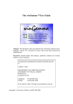
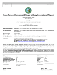
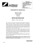
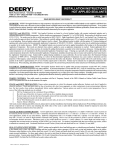
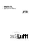
COOKING
EQUIPMENT
90 INDUSTRIAL PARK ROAD
P.O. BOX 880, SACO, MAINE / 04072-0880
(207) 282-1589
800-225-3958
FAX (207) 282-6283
SERVICE MANUAL
HOLMAN CONVEYOR SANDWICH WARMER
MODEL QT14
FOR SERVICE INFORMATION
U. S. AND CANADA CALL: TOLL FREE 1-800-225-3958
TABLE OF CONTENTS
TROUBLESHOOTING GUIDE
PAGE 1, 2, 3, 4
MAINTENANCE PROCEDURES
PAGE 4, 5, 6, 7
PARTS LIST
PAGE 9
ANACON PIC TESTING
PAGE 11
DRIVE CHAIN ALIGNMENT
PAGE 12
DRAWINGS
HEAT LIMIT SWITCH AND FUSE
PAGE 1
HEAT LIMIT SWITCH HEAT REFLECTOR/CRUMB TRAYS
PAGE 2
DRIVE SYSTEM
PAGE 3
HEATER TUBE INSTALLATION
PAGE 4
FAN MOTOR INSTALLATION
PAGE 5
DRIVE MOTOR INSTALLATION
PAGE 6
COMPONENT ARRANGEMENT
PAGE 7
MOTOR CONTROLLER
PAGE 8
WIRING DIAGRAM
PAGE 10
F:/MANUALS/Completed Manuals/ / QT14 Service Manual
REV. 5/282003 MJC/TLC
2M-HG0500
Electric Cooking Equipment for the Food Service Industry
Conveyor Toasters & Ovens
Cheese Melters
Broilers
Pretzel Bakers
PAGE 1
SERVICE MANUAL
HOLMAN CONVEYOR SANDWICH WARMER
MODEL QT14
WARNING: THE FOLLOWING PROCEDURES ARE TO BE PERFORMED BY A QUALIFIED SERVICE
TECHNICIAN ONLY!
WARNING: HIGH VOLTAGES ARE PRESENT IN THESE UNITS. MAKE SURE ALL INPUT POWER IS
OFF BEFORE INSTALLING/REMOVING ANY PARTS, SERVICING, OR CLEANING UNIT.
WARNING: CHECK WITH LOCAL POWER COMPANY TO DETERMINE ACTUAL VOLTAGE AT JOB
SITE.
NOTE: LUBRICATION OF DRIVE CHAIN WITH HIGH TEMP SYNTHETIC OR GRAPHITE BASED
LUBRICANT IS REQUIRED AS PERIODIC MAINTENANCE. CALL HOLMAN FACTORY SERVICE
DEPARTMENT FOR DETAILS.
TROUBLESHOOTING GUIDE
A. UNIT WILL NOT HEAT; CONVEYOR BELT WILL NOT TURN.
1) Be sure main Circuit Breaker is switched to the ON position and there is power at the outlet.
2) Check to see that the unit is connected to power and Master On/Off is switched to the ON position.
3) Be sure HEAT LIMIT SWITCH is pushed in (see below).
4) Check both fuses.
B. UNIT WILL NOT HEAT, CONVEYOR TURNS.
1) Check to see if the Master On/Off Switch is in the ON position.
2) Press heat limit switch, located on the exit end of the Sandwich Warmer beneath the unload tray
as shown above. If this reactivates the heater tubes, see section C.
3) Contact the Holman Cooking Equipment Factory Service Team at 1-800-225-3958 if assistance is
required.
Style A
Heat Limit Switch & Fuse
TROUBLESHOOTING GUIDE CONT. ON PAGE 2
Style B
Fuse Block
PAGE 2
SERVICE MANUAL
HOLMAN CONVEYOR SANDWICH WARMER
MODEL QT14
TROUBLESHOOTING GUIDE CONT.
C. HEAT LIMIT SWITCH
Your Holman Conveyor Sandwich Warmer is equipped with an automatically activated HEAT LIMIT SWITCH
that interrupts the heater tube connections if the air temperature in the control box exceeds 190°F (88°C). This
limit switch can be reset manually by pushing the button in the center of the switch that is located beneath the
unload tray.
Style A
Style B
THE HEAT LIMIT SWITCH CAN BE ACTIVATED IF THERE IS NOT A PROPER AMOUNT OF AIRFLOW
BEING GENERATED BY THE COOLING FANS. IF THIS OCCURS:
1) DISCONNECT UNIT FROM POWER SOURCE.
2) Check to see if air intake fans in the front of the unit are free of dust, grease or other obstructions.
3) Check to see if crumb trays (heat reflectors) are in place.
NEVER OPERATE UNIT WITHOUT CRUMB TRAYS IN POSITION AS THIS CAUSES OVERHEATING IN
THE CONTROL BOX.
TROUBLESHOOTING GUIDE CONT. ON PAGE 3
PAGE 3
SERVICE MANUAL
HOLMAN CONVEYOR SANDWICH WARMER
MODEL QT14
TROUBLESHOOTING GUIDE CONT.
D. CONVEYOR WILL NOT TURN, UNIT HEATS PROPERLY.
1) DISCONNECT UNIT FROM POWER SOURCE.
2) Check both fuses.
Style A
Style B
3) Check to see if there are obstructions in the conveyor system that may cause a jam.
4) If there are no obstructions found, manually move the conveyor belt to check for mechanical
binding. If conveyor does not move freely, call the Holman Cooking Equipment Factory Service
Team at (1-800-225-3958) as drive motor and/or variable speed control unit may have to be
replaced (refer to page 5 for instructions on replacing drive motor).
IF CONVEYOR STILL DOES NOT TURN
5) If conveyor turns freely, remove power supply panel and check for loose sprockets. Realign any
loose sprocket(s) and tighten allen screw.
6) Contact the Holman Cooking Equipment Factory Service Team at 1-800-225-3958 if assistance is
required.
DRIVEN SPROCKET
DRIVE CHAIN
DRIVE SPROCKET
TROUBLESHOOTING GUIDE CONT. ON PAGE 4
PAGE 4
SERVICE MANUAL
HOLMAN CONVEYOR SANDWICH WARMER
MODEL QT14
TROUBLESHOOTING GUIDE CONT.
E. CONVEYOR TURNS AT ONE SPEED REGARDLESS OF SPEED CONTROL SETTING.
1) Contact the Holman Cooking Equipment Factory Service Team at 1-800-225-3958, as variable
speed control unit may have to be replaced.
F. COOLING FANS DO NOT START.
1) DISCONNECT UNIT FROM POWER SOURCE.
2) Remove panels with fan motors and check fan blades for obstructions.
3) Check fan motor cords for secure connection.
4) Call Holman Factory Service Team, as the fan switches and/or fan motor(s) may have to be
replaced.
MAINTENANCE PROCEDURES
A. REPLACING HEATER TUBES (see below)
1) DISCONNECT UNIT FROM POWER SOURCE.
2) Carefully remove window in the back of the unit. See Operations Manual for detailed instructions
to remove window.
3) Remove front control panel and back panels by removing the Philips head screws in each panel.
Pull the top of each panel out slightly and lift up.
4) Locate defective heater tube and disconnect heater tube wires that require replacement from
terminal block connections.
5) Loosen screws holding the heater tube retainer in place. Slide the retainer up to allow the heater
tube to be removed, and tighten screws holding retainer.
6) GENTLY, pull defective heater tube out of unit.
7) GENTLY, place new heater tube into unit.
8) Once new heater tube is installed, loosen retainer screw, slide retainer back into original position
and tighten. Make sure the ends of the quartz heater tubes are free to move slightly.
9) Reconnect heater tube wires to terminal block connections.
10) Replace panels and test unit for proper operation.
MAINTENANCE PROCEDURES CONT. PAGE 5
PAGE 5
SERVICE MANUAL
HOLMAN CONVEYOR SANDWICH WARMER
MODEL QT14
MAINTENANCE PROCEDURES CONT.
B. REPLACING FAN MOTORS
1) DISCONNECT UNIT FROM POWER SOURCE.
2) Remove panel with the fan motor that needs to be replaced.
3) Unplug power supply cord from fan motor.
4) Remove (4) screws that hold fan motor and grill to cover.
5) Put replacement motor and grill in place and secure to the air intake cover with screws.
6) Reconnect power supply cord to fan motor.
7) Replace air intake panel.
8) Test to make sure air is being drawn into unit.
AIR INTAKE COVER
AIR INTAKE
FAN MOTOR
SECURED BY 4 SCREWS
C. REPLACING BELT DRIVE MOTOR
1) DISCONNECT UNIT FROM POWER SOURCE.
2) Carefully lay unit on top cover. (DO NOT LAY UNIT ON WINDOW SIDE AS DAMAGE TO GLASS
WILL OCCUR).
3) Remove back panel attached to power supply utility box and bottom control box cover. Drive chain
and sprockets will now be visible.
4) Loosen (4) screws holding motor in place. Slide the motor to provide slack in drive chain. Remove
the drive chain. Remove sprocket from motor shaft by loosening the Allen screw on the sprocket
collar.
MAINTENANCE PROCEDURES CONT. PAGE 6
PAGE 6
SERVICE MANUAL
HOLMAN CONVEYOR SANDWICH WARMER
MODEL QT14
MAINTENANCE PROCEDURES CONT.
5) Disconnect the drive motor leads to the internal wiring. Motors are rated 208 Volts or 240 Volts,
note which color leads are being used for these connections and which lead is capped with white
tape. The new drive motor should use the same arrangement.
6) Remove the four screws that hold the drive motor in place and remove drive motor.
DRIVEN SPROCKET
DRIVE CHAIN
DRIVE SPROCKET
7) Put the new motor in place and loosely attach with the four screws removed from step 5.
8) Replace the sprocket onto the motor shaft, and then replace the drive chain onto the sprockets.
9) Slide the drive motor until the drive chain has about 1/8" slack when lightly pushed at the center of
its top open run. Tighten the drive motor screws. Align drive and driven sprockets evenly before
tightening to prevent binding. Secure by tightening Allen screw on sprocket collar.
10) Rewire the drive motor as described in step 4 above. Replace the panels and test for proper
operation.
DRIVE SPROCKET WITH SET SCREW
CUT AWAY VIEW OF DRIVE MOTOR
IN CONTROL BOX.
DRIVE MOTOR
DRIVE MOTOR
MOUNTING SCREW
MAINTENANCE PROCEDURES CONT. PAGE 7
PAGE 7
SERVICE MANUAL
HOLMAN CONVEYOR SANDWICH WARMER
MODEL QT14
MAINTENANCE PROCEDURES CONT.
D. REPLACING THE VARIABLE SPEED MOTOR CONTROLLER (see below)
1) DISCONNECT UNIT FROM POWER SOURCE.
2) Carefully lay unit on top cover. (DO NOT LAY UNIT ON WINDOW SIDE AS DAMAGE TO GLASS
WILL OCCUR).
3) Remove Philips head screws holding control box cover in place.
4) Locate the motor controller mounted in the top center of the control box.
5) Wires from variable speed control go in to terminals located on the controller. Note the location of
the colored leads and remove wires for variable speed control. (refer to diagram on page 8 for
wire locations).
6) Disconnect the wires from terminals marked L, N, M1 and M2 (note which wires go to each
terminal).
7) Remove Philips head screws (4ea.) holding controller in place.
8) Mount replacement control in the same manner as the old control.
9) Reconnect wires removed from old control (refer to diagram on page 8 for wire locations).
10) Replace control box cover, place unit on legs and connect to power supply. Test for proper
operation.
11) Call the Holman Factory Service Team at 800-225-3958 if assistance is required.
COMPONENT ARRANGEMENT
1) Contactor/Relay
2) Heat Limit Switch
3) Drive Motor
1
4
5
3
2
4) Terminal Strip
5) Motor Control
PAGE 8
SERVICE MANUAL
HOLMAN CONVEYOR SANDWICH WARMER
MODEL QT14
CONTROLER FOR DRIVE SYSTEM
M1
M2
MOTOR
CONTROLLER
WHITE
BLACK
-
+ SP
L
N
EN
BLACK
RED
W
H
I
T
E
Y
E
L
L
O
W
B
L
U
E
SPEED CONTROL
POTENTIOMETER
PAGE 9
SERVICE MANUAL
HOLMAN CONVEYOR SANDWICH WARMER
MODEL QT14
HEATER TUBE PART LIST
PART No.
DESCRIPTION
QTY.
GE-198078
GE-198077
HEATER TUBE QUARTZ, TOP, 208V
HEATER TUBE QUARTZ, BOTTOM, 208V
10
6
GE-198081
GE-198080
HEATER TUBE QUARTZ, TOP, 240V
HEATER TUBE QUARTZ, BOTTOM, 240V
10
6
GE-198083
GE-198082
HEATER TUBE QUARTZ, TOP, 220V
HEATER TUBE QUARTZ BOTTOM, 220V
10
6
PARTS LIST
PART No.
DESCRIPTION
Qty.
PART No.
DESCRIPTION
Qty.
GE-402651
Small Heater Tube Retainer
4
2E-200574
Fan Switch
1
GE-402359
Large Heater Tube Retainer
1
2U-200577
Fan Motor
2
GD-160008
Conveyor Belt
1
2R-200562
Grill Fan Motor
2
2B-200626
Quick Clip Belt Links
3
2R-200721
Fan Blade 3”
1
2P-200785
Bushing, Spring loaded
2
2E-200535
Contactor/Relay, 40 amp
2
2P-200766
Spring
2
2U-200579
Motor Controller
1
GD-100924
Drive Shaft
1
2J-200427
Pilot Light
1
GE-100909
Idler Shaft
1
GE-118064
Speed Control
1
GE-100716
Center Idler Shaft
1
2E-200552
Rocker Switch
1
GB-112262
Shaft Bushing
4
2R-200761
Control Knob
1
2U-200509
Drive Motor (right to left)
1
2Q-200588
Neo-Ceram Window
1
2U-200504
Drive Motor (left to right)
1
GE-101029
Crumb Tray
2
ZZ-150008
Drive Chain
1
GE-100944
Unload Tray
1
2P-115362
Driven Sprocket
1
GE-402654
Lower Crumb Tray
1
2P-200648
Drive Sprocket
1
2R-200715
Leg, 4" Metal
4
2E-200566
Reset Switch
1
PAGE 10
SERVICE MANUAL
HOLMAN CONVEYOR SANDWICH WARMER
MODEL QT14
WIRE DIAGRAM
PAGE 11
SERVICE MANUAL
HOLMAN CONVEYOR SANDWICH WARMER
MODEL QT14
Anacon Potentiometer Input Circuit Testing
This check can be performed to verify the health of the analog input circuitry.
Overview:
For the Speed potentiometer to function properly it needs 5V across its terminals. For this the drive produces a
5V output for user connection. The terminals are labeled “+” and “-“. They are located on the lower left corner
of the drive. The potentiometer then uses this voltage to send a signal from 0 to 5 volts back to the drive as a
speed reference.
Safety:
Great care should be taken when testing the potentiometer because of the high voltage potential. There is only
5 volts from lead to lead but when referenced to ground the voltage may be much higher. In fact it could be as
high as the applied power to the drive. The individual connection points are very close together. Care should
be taken not to short across them with the meter leads.
Reference Voltage Check:
A meter connected to “+” and “-“ should read ~5V. If readings are otherwise try disconnecting the
potentiometer and re-test.
Speed Reference Check:
To check the potentiometers health connect a meter from the “-“ terminal on the drive and the “sp” terminal. As
you rotate the pot from one extreme to the other you should see a smooth transition from ~0 to ~5 Volts DC or
~5 to ~0 Volts DC.
PAGE 12
SERVICE MANUAL
HOLMAN CONVEYOR SANDWICH WARMER
MODEL QT14
Drive Chain Alignment
Note: that during factory assembly, a 1/8" side-to-side play is adjusted into the driveshaft to allow for
chassis expansion.
Unit must be cool.
Do NOT adjust position of the sprocket on the drive shaft.
Insert 1/16" spacer, i.e., a drill bit, between driveshaft sprocket and adjacent washer.
Push the sprocket against the 1/16” spacer, which results in the sprocket snug against the spacer, spacer
against the washer, and washer against the bearing assembly.
Measure dimension A, the distance from the chassis to the center of the sprocket.
Adjust the sprocket on the drive motor so that dimension B, the distance from the chassis to the center of the
motor sprocket is equal to dimension A+/- 1/16”.