1
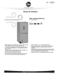
USER’S INFORMATION MANUAL
FOR COMMUNICATING MODULATING CONDENSING
GAS FURNACES
! Recognize this symbol as an indication of Important Safety Information!
!
WARNING
!
FOR YOUR SAFETY
!
WARNING
IF THE INFORMATION IN THESE INSTRUCTIONS
IS NOT FOLLOWED EXACTLY, A FIRE OR EXPLOSION MAY RESULT, CAUSING PROPERTY DAMAGE, PERSONAL INJURY OR DEATH.
NOTE TO INSTALLER: REVIEW THIS
MANUAL WITH THE USER AND LEAVE
IT WITH THE EQUIPMENT.
DO NOT DESTROY. PLEASE READ
CAREFULLY AND KEEP IN A SAFE
PLACE FOR FUTURE REFERENCE.
— Do not store or use gasoline or other flammable
vapors and liquids, or other combustible materials
in the vicinity of this or any other appliance.
— WHAT TO DO IF YOU SMELL GAS
• Do not try to light any appliance.
• Do not touch any electrical switch; do not use
any phone in your building.
• Immediately call your gas supplier from a neighbor’s phone. Follow the gas supplier’s instructions.
• If you cannot reach your gas supplier, call the
fire department.
• Do not rely on smell alone to detect leaks. Due
to various factors, you may not be able to smell
fuel gases.
• U.L. recognized fuel gas and CO detectors are
recommended in all applications, and their
installation should be in accordance with the
manufacturer’s recommendations and/or local
laws, rules, regulations, or customs.
— Installation and service must be performed by a
qualified installer, service agency or the gas supplier.
PROPOSITION 65: THIS PRODUCT CONTAINS
CHEMICALS KNOWN TO THE STATE OF CALIFORNIA TO CAUSE CANCER, BIRTH DEFECTS
OR OTHER REPRODUCTIVE HARM.
92-20802-98-01
SUPERSEDES 92-20802-98-00
GENERAL INFORMATION
!
WARNING
DUCT LEAKS CAN CREATE AN
UNBALANCED SYSTEM AND DRAW
POLLUTANTS SUCH AS DIRT, DUST,
FUMES AND ODORS INTO THE
HOME CAUSING PROPERTY DAMAGE. FUMES AND ODORS FROM
TOXIC, VOLATILE OR FLAMMABLE
CHEMICALS, AS WELL AS AUTOMOBILE EXHAUST AND CARBON
MONOXIDE (CO), CAN BE DRAWN
INTO THE LIVING SPACE THROUGH
LEAKING DUCTS AND UNBALANCED
DUCT SYSTEMS CAUSING PERSONAL INJURY OR DEATH (SEE FIGURE
1).
• IF AIR-MOVING EQUIPMENT OR
DUCTWORK IS LOCATED IN
GARAGES OR OFF-GARAGE
STORAGE AREAS - ALL JOINTS,
SEAMS, AND OPENINGS IN THE
EQUIPMENT AND DUCT MUST BE
SEALED TO LIMIT THE MIGRATION
OF TOXIC FUMES AND ODORS
INCLUDING CARBON MONOXIDE
FROM MIGRATING INTO THE LIVING SPACE.
2
• IF AIR-MOVING EQUIPMENT OR
DUCTWORK IS LOCATED IN
SPACES CONTAINING FUEL BURNING APPLIANCES SUCH AS WATER
HEATERS OR BOILERS - ALL
JOINTS, SEAMS, AND OPENINGS
IN THE EQUIPMENT AND DUCT
MUST ALSO BE SEALED TO PREVENT DEPRESSURIZATION OF THE
SPACE AND POSSIBLE MIGRATION
OF COMBUSTION BYPRODUCTS
INCLUDING CARBON MONOXIDE
INTO THE LIVING SPACE.
!
NOTICE
IMPROPER INSTALLATION, OR
INSTALLATION NOT MADE IN
ACCORDANCE WITH THE CSA
INTERNATIONAL (CSA) CERTIFICATION OR THESE INSTRUCTIONS,
CAN RESULT IN UNSATISFACTORY
OPERATION AND/OR DANGEROUS
CONDI-TIONS AND ARE NOT COVERED BY THE UNIT WARRANTY.
!
NOTICE
IN COMPLIANCE WITH RECOGNIZED CODES, IT IS RECOMMENDED THAT AN AUXILIARY DRAIN
PAN BE INSTALLED UNDER ALL
EVAPORATOR COILS OR UNITS
CONTAINING EVAPORATOR COILS
THAT ARE LOCATED IN ANY AREA
OF A STRUCTURE WHERE DAMAGE TO THE BUILDING OR BUILDING CONTENTS MAY OCCUR AS A
RESULT OF AN OVERFLOW OF
THE COIL DRAIN PAN OR A STOPPAGE IN THE PRIMARY CONDENSATE DRAIN PIPING. SEE ACCESSORIES SECTION OF THESE
INSTRUCTIONS FOR AUXILIARY
HORIZONTAL OVERFLOW PAN
INFORMATION (MODEL RXBM).
IMPORTANT INFORMATION
ABOUT EFFICIENCY AND
INDOOR AIR QUALITY
Central cooling and heating equipment
is only as efficient as the duct system
!
that carries the cooled or heated air. To
maintain efficiency, comfort and good
indoor air quality, it is important to have
the proper balance between the air
being supplied to each room and the air
returning to the cooling and heating
equipment.
WARNING
CARBON MONOXIDE (CO) IS A COLORLESS, ODORLESS, POISONOUS
GAS THAT CAN CAUSE SEVERE PERSONAL INJURY OR DEATH. CARBON
MONOXIDE CAN BE PRODUCED BY ANY FUEL-BURNING DEVICE, INCLUDING BUT NOT LIMITED TO:
• MOTOR VEHICLES
• GENERATORS AND OTHER GASOLINE POWERED TOOLS AND ENGINES
• GAS AND FUEL-OIL APPLIANCES
• CHARCOAL OR GAS GRILLS
• WOOD OR GAS FIREPLACES AND STOVES
• OUTDOOR CAMPING EQUIPMENT
CARBON MONOXIDE FROM ANY ONE OF THESE DEVICES CAN BE INADVERTENTLY DRAWN INTO AND DISTRIBUTED THROUGH THE LIVING
SPACE BY THE NORMAL OPERATION OF THE CENTRAL HEATING / AIR
CONDITIONING SYSTEM (SEE FIGURE 1).
APPLIANCES AND FUEL BURNING DEVICES MUST BE INSTALLED, OPERATED AND MAINTAINED IN ACCORDANCE WITH THE MANUFACTURER’S
INSTRUCTIONS.
GASOLINE-POWERED TOOLS AND MOTOR VEHICLES MUST NOT BE
OPERATED IN ENCLOSED SPACES, SUCH AS BASEMENTS, CRAWLSPACES, OR GARAGES, EVEN WITH DOORS AND WINDOWS OR VENTS
OPEN, AS EXHAUST FUMES INCLUDING CARBON MONOXIDE CAN BUILD
UP AND SEEP INTO THE LIVING SPACE THROUGH CRACKS AND OPENINGS IN THE STRUCTURE. TOXIC FUMES, INCLUDING CARBON MONOXIDE, CAN ALSO BE DRAWN INTO THE LIVING SPACE THROUGH OPENINGS AND SEAMS IN THE CENTRAL HEATING AND AIR CONDITIONING
EQUIPMENT AND / OR DUCTWORK.
FOR THESE REASONS, THE U.S. CONSUMER PRODUCT SAFETY
COMMISSION (CPSC) RECOMMENDS THAT EVERY HOME HAVE AT LEAST
ONE CARBON MONOXIDE ALARM INSTALLED IN THE HALLWAY NEAR
THE BEDROOMS IN EACH SEPARATE SLEEPING AREA OF THE HOME.
CARBON MONOXIDE ALARMS SHOULD BE CERTIFIED TO THE REQUIREMENTS OF THE MOST RECENT UL, IAS OR CSA STANDARD, AND SHOULD
BE INSTALLED, OPERATED AND MAINTAINED IN ACCORDANCE WITH THE
ALARM MANUFACTURER’S INSTRUCTIONS.
FIGURE 1
MIGRATION OF DANGEROUS SUBSTANCES, FUMES, AND ODORS INTO LIVING SPACES
Proper balance and sealing of the duct
system improves the efficiency of the
heating and air conditioning system and
improves the indoor air quality of the
home by reducing the amount of airborne pollutants that enter homes from
spaces where the ductwork and / or
equipment is located. The manufacturer
and the U.S. Environmental Protection
Agency’s Energy Star Program recommend that central duct systems be
checked by a qualified contractor for
proper balance and sealing.
RECEIVING
Immediately upon receipt, all cartons
and contents should be inspected for
transit damage. Units with damaged cartons should be opened immediately. If
damage is found, it should be noted on
the delivery papers, and a damage claim
filed with the last carrier.
• After unit has been delivered to job
site, remove carton taking care not to
damage unit.
• Check the unit rating plate for unit
size, electric heat, coil, voltage,
phase, etc. to be sure equipment
matches what is required for the job
specification.
• Read the entire instructions before
starting the installation.
• Some building codes require extra
cabinet insulation and gasketing when
unit is installed in attic applications.
• If installed in an unconditioned space,
apply caulking around the power
wires, control wires, refrigerant tubing
and condensate line where they enter
the cabinet. Seal the power wires on
the inside where they exit conduit
opening. Caulking is required to prevent air leakage into and condensate
from forming inside the unit, control
box, and on electrical controls.
• Install the unit in such a way as to
allow necessary access to the
coil/filter rack and blower/control compartment.
• Install the unit in a level position to
ensure proper condensate drainage.
Make sure unit is level in both directions within 1/8”.
• Install the unit in accordance with any
local code which may apply and the
national codes. Latest editions are
available from: “National Fire
Protection Association, Inc.,
Batterymarch Park, Quincy, MA
02269.” These publications are:
• ANSI/NFPA No. 70-(Latest Edition)
National Electrical Code.
• NFPA90A Installation of Air
Conditioning and Ventilating Systems.
• NFPA90B Installation of warm air
heating and air conditioning systems.
• The equipment has been evaluated in
accordance with the Code of Federal
Regulations, Chapter XX, Part 3280.
3
INTRODUCTION TO YOUR FURNACE
Thank you for the purchase of your new modulating gas furnace! This furnace is designed to be the ultimate in heating
comfort and is the only true modulating gas furnace available
on the market today.
The modulating gas furnace provides a superior level of
comfort due to the interaction of seven basic components:
• Variable Output Thermostat - Whereas conventional thermostats only send an On/Off signal to the furnace, the thermostat for the modulating furnace system is specially
designed to indicate the exact heating requirements of the
conditioned space. This is accomplished by a logic control
routine that accurately senses the space load, minimizes
recovery times, reduces temperature swings and optimizes
system efficiency and performance.
• Fully Communicatiing Thermostat Modulating Gas Valve The gas valve has the conventional redundant solenoid
valves for inherent safety, but also has a third operator for
capacity control. This operator is actually a servo valve
FIGURE 2
UPFLOW FURNACE
ITEM
NO. PART NAME
1
ITEM
NO. PART NAME
13
14
BURNER
5
PRESSURE SWITCH ASSEMBLY
17
GAS VALVE
4
6
TRANSFORMER
EXHAUST TRANSITION
7
CONNECTOR
10
VENT CAP SHIPPING PLUG
8
9
11
12
MAIN LIMIT
EXHAUST AIR PIPE
FLAME SENSOR
OVERTEMPERATURE SWITCH
15
16
18
19
20
21
22
ST-A1123-01_01
TOP PLATE
DOOR SWITCH
JUNCTION BOX
• Furnace Controller - The furnace controller provides all of
the ignition and safety functions of the typical IFC as well as
interpreting the signals from the thermostat. The furnace
controller will optimize furnace performance by monitoring all
thermostat and temperature inputs and insuring the stable
operation of the inducer, gas valve and indoor blower motor.
• ECM Variable Speed Blower - The airflow through the duct
work is varied to meet the load demand. Airflow as low as
300 CFM is achieved by the response of a brushless permanent magnet variable speed blower motor.
• Two Speed Draft Inducer - To insure clean combustion
and peak efficiency, the induced draft motor speed is adjusted based on the gas valve setting to provide the proper
amount of combustion air to the burners.
FIGURE 3
DOWNFLOW FURNACE
2
3
4
CONDENSATE TRAP
which varies the input rate of the furnace proportionally to
the signal from the controller. The modulating furnace can
operate anywhere from 40% to 100% of the nameplate input
of the furnace.
IGNITER
COMBUSTION AIR INLET
ITEM
NO. PART NAME
1
2
3
4
5
GAS VALVE
PRESSURE SWITCH ASSEMBLY
BLOWER HOUSING
POWER FACTOR CHOKE
BLOWER MOTOR
INDUCED DRAFT BLOWER
6
DOOR SWITCH
BLOWER MOTOR
9
HALC
POWER FACTOR CHOKE
INTEGRATED FURNACE CONTROL
BLOWER HOUSING
7
8
10
11
12
JUNCTION BOX
COMBUSTION AIR INLET
TOP PLATE
VENT CAP SHIPPING PLUG
OUTLET AIR PIPE
ITEM
NO. PART NAME
13
14
15
16
17
18
19
20
21
22
ST-A1123-01_02
INTEGRATED FURNACE CONTROL
TRANSFORMER
INDUCED DRAFT BLOWER
CONNECTOR
EXHAUST TRANSITION
CONDENSATE TRAP
IGNITER
OVERTEMPERATURE SWITCH
BURNER
FLAME SENSOR
➤ FIGURE 3
HORIZONTAL FURNACE (-)GJD
ITEM
NO. PART NAME
1
2
3
4
5
6
7
8
9
10
11
12
13
GAS VALVE
CAPACITOR (FOR INDUCER)
LOW PRESSURE SWITCH
HIGH PRESSURE SWITCH
BLOWER HOUSING
POWER FACTOR CHOKE
BLOWER MOTOR
DOOR SWITCH
JUNCTION BOX
COMBUSTION AIR INLET
HALC
TOP PLATE
VENT CAP PLUG
ITEM
NO. PART NAME
14
15
16
17
18
19
20
21
22
23
24
25
OUTLET AIR PIPE
INTEGRATED FURNACE CONTROL
TRANSFORMER
INDUCED DRAFT BLOWER
CONNECTOR
EXHAUST TRANSITION
CONDENSATE TRAP
IGNITER
OVERTEMPERATURE SWITCH
BURNER
FLAME SENSOR
FACTORY-INSTALLED STREET ELBOW
ST-A107801.S01
5
• Supply Air Sensors - This thermister assembly, is a field
installed air probe, communicate the furnace temperature
rise to the integrated furnace control. The integrated furnace
control uses this information to calculate field conditions during calibration to insure optimal efficiency and comfort during
normal operation.
This furnace has been designed to give you many years of
efficient, dependable home comfort. With regular maintenance, this furnace will operate superbly year after year.
INSTALLATION INFORMATION
Please take the time to fill out the information below and
read this manual to familiarize yourself with operation, maintenance schedule, and safety operation.
IMPORTANT: READ THESE INSTRUCTIONS THOROUGHLY BEFORE ATTEMPTING TO OPERATE THIS
FURNACE.
Date Installed
AC SYSTEM
Address
Serial No.
Dealer Name
City
State
Telephone No.
Model No.
INDOOR COIL
Zip
Model No.
Serial No.
FURNACE
Model No.
Serial No.
SAFETY PRECAUTIONS
SIGNAL WORDS
There are some safety precautions
which must be understood and followed by all users of equipment such
as your furnace, where flames, gas,
electricity and rotating parts are present. To alert you to the above potential hazards, we use the signal words
“WARNING” and “CAUTION” throughout this manual and safety labels
attached to the furnace.
Read carefully and pay special attention to all warnings and cautions in this
manual. They are defined and
designed as follows to help you recognize and avoid the potential hazards of
operating this furnace:
!
WARNING
INDICATES A POTENTIALLY
HAZARDOUS SITUATION
WHICH, IF NOT AVOIDED,
COULD RESULT IN PROPERTY DAMAGE, SERIOUS
INJURY OR DEATH.
!
CAUTION
Indicates a potentially hazardous
situation which, if not avoided,
could result in property damage,
or minor or moderate injury.
6
POSSIBILITY OF FIRE OR
EXPLOSION
!
WARNING
THIS FURNACE OPERATES BY
BURNING GAS INSIDE YOUR
HOME. THIS CREATES THE POSSIBILITY OF FIRE OR AN EXPLOSION WHICH CAN RESULT IN
PROPERTY DAMAGE, PERSONAL
INJURY OR DEATH. YOU MUST
READ AND FOLLOW ALL OF
THESE SAFETY PRECAUTIONS
TO HELP ENSURE SAFE OPERATION OF YOUR FURNACE.
• Do not test for gas leaks with a match
or flame.
• Do not use this furnace with any other
gas than the one listed on the rating
plate.
• Follow the furnace lighting instructions carefully to be sure all gas
fumes are cleared before lighting the
furnace.
• Check carefully for gas before lighting
a furnace. Do not rely on smell alone
to detect gas. Use a UL recognized
fuel gas detector and a soap and
water solution on the pipes to check
for gas leaks.
• A damaged gas control knob can
cause gas to leak. Do not hit or damage the knob. Do not force the knob
with tools. Use only your hand to turn
it to “ON” or “OFF”. Call the a quali-
•
•
•
•
•
•
fied installer, service agency or the
gas supplier immediately if you have
problems turning the knob.
Should overheating occur, or the gas
valve fail to shut off the gas supply,
turn off the manual gas valve to the
furnace before turning off the electrical supply.
Soot buildup indicates a serious combustion problem that requires immediate correction. Turn the gas supply
“OFF” until the furnace is repaired.
Contact a qualified installer, service
agency or the gas supplier immediately to inspect the furnace.
Do not place, store or use gasoline or
other flammable vapors and liquids
on, against, or around the furnace
jacket.
Do not store combustible materials
near the furnace. The furnace must
have adequate clearances from all
combustible materials such as clothing, paper, cardboard, wood or cleaning materials to prevent them from
igniting.
Keep any furnace installed in an attic
or other insulated space free and
clear of insulating material. Examine
the furnace area when installing the
furnace or adding insulation. Some
materials may be combustible.
Any additions, changes or conversions required in order for the furnace
to satisfactorily meet the application
needs should be made by a qualified
installer, service agency or the gas
supplier, using factory specified or
approved parts. Read your Warranty.
Contact the WARRANTOR for conversion information. This furnace was
equipped at the factory for use on
NATURAL GAS ONLY. Conversion
to LP GAS requires a special kit supplied by the WARRANTOR.
STARTING YOUR
FURNACE
FIGURE 6
STANDARD HORIZONTAL
DIRECT VENTING
DANGER FROM
ASPHYXIATION
!
WARNING
THIS FURNACE OPERATES BY
BURNING GAS INSIDE YOUR
HOME. IMPROPER OR INCOMPLETE BURNING OF THIS GAS
CAN RESULT IN THE FORMATION
OF CARBON MONOXIDE. IF
INTRODUCED INTO THE LIVING
SPACE, THIS CAN CAUSE DIZZINESS, NAUSEA, OR DEATH BY
ASPHYXIATION. YOU MUST
READ AND OBSERVE THE SAFETY RULES BELOW TO PREVENT
OXYGEN DEPLETION OR
UNBURNED GAS OR COMBUSTION FROM ESCAPING INTO THE
LIVING SPACE OF YOUR RESIDENCE.
• Do not operate this furnace without
provisions for an adequate combustion air supply.
• Do not allow snow, ice, or any other
debris to accumulate in or around the
exhaust and intake terminations of
this furnace. These are extended
through the roof or horizontally
through the sidewall of the structure.
See Figures 5 & 6. Blockage of the
intake and exhaust can result in inadequate combustion air as well as
inadequate unit performance or nuisance tripping.
FIGURE 5
STANDARD VERTICAL
DIRECT VENTING
I407
I407
• Prevent flue gases from escaping into
your residence. Deterioration of the
venting system, or soot build-up can
cause leaks into the system. Have a
qualified installer, service agency or the
gas supplier replace damaged parts or
repair obstructions in a deteriorated
vent system immediately.
• Do not use this furnace if any part has
been under water. A flood-damaged
furnace is extremely dangerous.
Attempts to use the furnace can result
in fire or explosion. A qualified service
agency should be contacted to inspect
the furnace and to replace all gas controls, control system parts, electrical
parts that have been wet or the furnace,
if deemed necessary.
• To prevent carbon monoxide poisoning,
all blower doors and compartment covers must be replaced after the furnace
is serviced. Do not operate the unit
without all panels and doors securely in
place.
SYSTEM OPERATION
INFORMATION
• Keep the air filters clean. Your heating
system will operate more efficiently and
provide better heating, more economically.
• Arrange your furniture and drapes so
that the supply air registers and return
air grilles are unobstructed.
• Close doors and windows. This will
reduce the heating load on your system.
• Avoid excessive use of exhaust fans.
• Do not permit the heat generated by
television, lamps, or radios to influence
the thermostat operation.
• If you desire to operate your system
with constant air circulation, consult
your thermostat manual or please ask
advice from a qualified installer, service
agency or the gas supplier.
IMPORTANT: FOR COMPLETE
OPERATION AND SET UP OF YOUR
THERMOSTAT REFER TO THE MANUAL INCLUDED IN THE LITERATURE
PACKET SHIPPED WITH THIS FURNACE.
LIGHTING INSTRUCTIONS
This appliance is equipped with a direct
spark ignition device. This device lights
the main burners each time the room
thermostat calls for heat. DO NOT try to
light the burner by hand. See lighting
instructions on the furnace.
1. Remove the burner access door.
2. Set the thermostat to the lowest setting.
3. Turn the gas control knob counterclockwise to the “ON” position.
4. Replace the burner access door.
5. Turn on the electrical power.
6. Set the room thermostat to a point
above the room temperature to light
the main burners. After the burners are
lit, set the room thermostat to a desired
temperature.
! WARNING
BE SURE THAT THE MANUAL GAS
CONTROL HAS BEEN IN THE “OFF”
POSITION FOR AT LEAST FIVE
MINUTES. DO NOT ATTEMPT TO
MANUALLY LIGHT THE MAIN
BURNERS. FAILURE TO FOLLOW
THIS WARNING CAN CAUSE A
FIRE OR AN EXPLOSION RESULTING IN PROPERTY DAMAGE, PERSONAL INJURY OR DEATH.
7. If the appliance will not operate, follow
the instructions “To Turn Off Gas To
The Appliance” and call your service
technician or gas supplier.
TO TURN OFF GAS TO THE
APPLIANCE
!
WARNING
SHOULD OVERHEATING OCCUR
OR THE GAS SUPPLY FAIL TO
SHUT OFF, SHUT OFF THE MANUAL GAS VALVE TO THE APPLIANCE BEFORE SHUTTING OFF
THE ELECTRICAL SUPPLY. FAILURE TO DO SO CAN CAUSE AN
EXPLOSION OR FIRE RESULTING
IN PROPERTY DAMAGE, PERSONAL INJURY OR DEATH.
IMPORTANT: SHUT OFF THE MANUAL
GAS VALVE LOCATED IN THE GAS
SUPPLY PIPING OUTSIDE THE FURNACE CASING.
1. Set the thermostat to the lowest setting.
2. Turn off all electric power to the appliance on which service is to be performed.
3. Remove the burner access door.
4. Turn the gas control knob to the “OFF”
position.
5. Replace the burner access door.
7
SEQUENCE OF OPERATION
Startup For Systems Configured
With Communications
! WARNING
INSTALLATION OF LINE VOLTAGE AND GAS MUST BE PERFORMED ACCORDING TO
INSTRUCTIONS WRITTEN IN
THIS MANUAL. FAILURE TO DO
SO COULD RESULT IN INJURY
OR DEATH.
When the furnace is configured for
communications, the components on
the network (i.e. furnace, thermostat
and condenser) must establish communications before engaging a heat (or
other) thermostat demand. The procedure for establishing communications
is automatic and is described below.
Once the communicating wiring is
properly installed and the furnace is
connected to line voltage, the system
can be turned on. The thermostat will
display the following text :
SEARCHING
is displayed several times for several
seconds. Next, the text
FURNACE FOUND
and
AIR CONDITIONER FOUND
or
HEAT PUMP FOUND
(depending on which is installed in the
system) will be displayed. The process
can take several minutes (up to a maximum of 30) to complete. If these messages are not displayed within 30 minutes after energizing the system, communications can not be established.
There are many reasons why communications may not be established –
including improper settings of the
“TERM” and “BIAS” switches (see
BIAS/ TERMINATION) and improper
wiring.
The order in which these messages will
be displayed will depend on which
components are energized first. The
MAINTENANCE
IMPORTANT: IT IS RECOMMENDED
THAT AN ANNUAL INSPECTION OF
YOUR FURNACE BE MADE BY A
QUALIFIED INSTALLER, SERVICE
AGENCY OR THE GAS SUPPLIER.
DURING THE ANNUAL INSPECTION,
IT IS RECOMMENDED THAT 120VAC
POWER BE TURNED OFF, THEN
BACK TO THE ON POSITION.
REAPPLYING120VAC INITIATES A
CALIBRATION CYCLE TO ENSURE
OPTIMUM SYSTEM OPERATION.
8
order listed here assumes that the furnace and condenser are energized at
the same time. If not, the order of display will be in the order that the components are turned on.
When the system has found all necessary components, the text area of the
communicating thermostat will go
blank. This is an indicator that the system is operating properly. Proceed by
engaging a typical thermostat call to
determine if operation is correct as
described in the section of this book
titled START UP PROCEDURES” to
test heating, cooling and fan operation
and to make necessary adjustments.
The heating cycle is always initiated by a
24 volt signal on W of the thermostat.
When the controller senses a heat call or
with a communicating signal from a communicating thermostat, the following
sequence occurs:
• High and low pressure switches are
checked to insure contacts are open.
• Inducer is powered on high speed for a
thirty (30) second prepurge.
• Pressure switches are monitored as
the inducer creates the vacuum to
close the contacts.
• The gas valve servo or solenoid is
energized at 100%. (No flow yet.)
• The controller generates a spark
across the electrodes.
• The main solenoid on the gas valve is
energized, allowing gas to flow to the
burners.
• When flame is proven, the ignition control is de-energized - 8 second maximum trial time.
• The gas valve maintains 100% rate
through the warm-up period - 20 seconds.
Heating Cycle Initiation
The heating cycle is always initiated by a
24 volt signal on W1 or with a communicating signal from a communicating thermostat. When the controller senses a
heat call, the following sequence occurs:
Heating Cycle Response
!
WARNING
THIS FURNACE CONTAINS MOVING/ROTATING COMPONENTS
AND USES HOUSEHOLD ELECTRICAL CURRENT. FOLLOW THE
SAFETY RULES BELOW TO
AVOID CUTS, BURNS OR ELECTRICAL SHOCK WHICH CAN
RESULT IN SEVERE PERSONAL
INJURY OR DEATH.
MODULATING FUNCTION:
(“W” and “V” signal inputs, refer to dip
switch set SW2 on IFC)
After the warm-up period, the furnace
will respond to the thermostat demand
by adjusting the gas valve pressure and
blower speed anywhere between 40% to
100% heating capacity.
➤ TWO-STAGE FUNCTION:
(Two-stage function only applies when
both switches of SW2 are in the “ON”
position and a two-stage thermostat is
installed 24V.)
After the warm-up period, the furnace
will respond to the thermostat demand
by adjusting the gas valve pressure and
blower heating speeds to the “W” signal
values. “W” only = 40% gas valve pressure and blower heating speed. “W2” =
65% gas valve pressure and blower
heating speed for first five minutes and
100% thereafter. Also, if the call for heat
ends, the furnace terminates at the present rate.
➤ SINGLE-STAGE FUNCTION:
(“W” signal only)
After the warm-up period, the furnace
will respond to the thermostat demand
by altering the gas valve pressure and
blower speed as follows:
Phase 1: 0 to 5 minutes = 40% of furnace capacity (gas valve output and
blower speed)
Phase 2: 5 to 12 minutes = 65% of furnace capacity (gas valve output and
blower speed)
Phase 3: After 12 minutes = 100% of
furnace capacity (gas valve output and
blower speed)
NOTE: If the call for heat ends during
any phase, the furnace will terminate
immediately at the firing rate of that
phase.
Heating Cycle Termination
(“W” signal only, refer to dip switch set
SW2 on IFC)
When the heat call is removed, the heating cycle will end and the furnace will
shut down and return to the proper off
cycle operation.
POSSIBILITY OF BURNS
OR ELECTRICAL INJURY
• Do not perform any service or maintenance on the furnace while it is operating. Read and follow the service
instructions provided with this furnace
before beginning any service or maintenance work.
• Do not open the blower compartment,
disassemble, or remove any components while the furnace is operating.
This may expose sharp edges or
points which could cause cuts, hot
surfaces which could cause burns,
and electrical circuits which could
cause shocks.
• Instruct children on the safety hazards associated with furnaces. Keep
children away from the furnace at all
times.
!
CAUTION
DO NOT OPERATE YOUR SYSTEM FOR EXTENDED PERIODS
WITHOUT FILTERS. A PORTION
OF THE DUST ENTRAINED IN
THE AIR MAY TEMPORARILY
LODGE IN THE AIR DUCT RUNS
AT THE SUPPLY REGISTERS.
ANY RECIRCULATED DUST WILL
BE HEATED AND CHARRED BY
CONTACT WITH THE FURNACE
HEAT EXCHANGER. THIS
RESIDUE WILL SOIL CEILINGS,
WALLS, DRAPES, CARPETS AND
OTHER HOUSEHOLD ARTICLES.
FILTER MAINTENANCE
Have your qualified installer, service
agency or the gas supplier instruct you
on how to access your filters for regular
maintenance.
• Keep air filters clean at all times.
Vacuum dirt from filter, wash with
detergent and water, air dry thoroughly and reinstall.
• After filters are cleaned and returned
to the furnace, be sure doors are
properly reinstalled. If you are not
totally sure of this procedure, consult
qualified installer, service agency or
the gas supplier.
REMOVING FILTERS
FILTER IN BOTTOM OR SIDE
LOCATION
FIGURE 7
UPFLOW SIDE FILTER LOCATION
1. Remove the blower compartment
access door.
2. Disengage the filter retaining rod and
pull filter out.
3. Clean filter and reinstall.
4. Replace the blower compartment
access door.
LUBRICATION
The blower motor and induced draft
motor are permanently lubricated by
the manufacturer and do not require
further attention.
IMPORTANT: DO NOT ATTEMPT TO
LUBRICATE THE BEARINGS ON THE
BLOWER MOTOR OR THE INDUCED
DRAFT BLOWER MOTOR. ADDITION
OF LUBRICANTS CAN REDUCE THE
MOTOR LIFE AND VOID THE WARRANTY.
The blower compartment and motor
should be inspected and cleaned periodically by your qualified installer, service agency or the gas supplier to prevent the possibility of overheating due
to an accumulation of dust and dirt on
the windings or on the motor exterior.
And, as suggested elsewhere in these
instructions, keep the air filters clean
because dirty filters can restrict airflow
and the motor depends on sufficient air
flowing across and through it to keep it
from overheating.
COMBUSTION AIR AND
VENT SYSTEM
1. It is recommended that an annual
inspection of your furnace’s combustion air and vent system be done by
a qualified installer, service agency
or the gas supplier.
I332
FIGURE 8
UPFLOW BOTTOM FILTER INSTALLATION
!
WARNING
IF DIRT, RUST, SOOT OR SCALE
ACCUMULATIONS ARE PRESENT,
DO NOT OPERATE THE FURNACE.
INSPECT THE HEAT EXCHANGER
FOR LEAKS. LEAKS CAN CAUSE
TOXIC FUMES TO ENTER THE
HOME AND CAUSE CARBON
MONOXIDE POISONING OR DEATH.
2. Turn OFF the electrical supply to the
furnace and remove the access
doors.
3. Inspect the gas burners for dirt, rust
or scale and clean as necessary.
4. Inspect the flue connection area and
vent pipe. Be sure that the vent connector is in place and slopes upward
and is physically sound, without
holes or excessive corrosion.
5. Be sure that the return air duct connections are physically sound, are
sealed to the furnace casing and terminate outside the space containing
the furnace.
ADS-5422-01
9
!
WARNING
CHECK THE VENT PIPE SECTIONS
FOR DETERIORATION AND CHECK
JOINT FITTINGS FOR THEIR
INTEGRITY. IF IT HAS BECOME DISCONNECTED TOXIC FUMES CAN
ENTER THE HOME AND CAUSE
CARBON MONOXIDE POISONING
OR DEATH. DO NOT OPERATE THIS
FURNACE. APPROPRIATE SERVICE
MUST BE APPLIED.
FIGURE 9
DOWNFLOW FILTER INSTALLATION
AIRFLOW
6. Be sure the physical support of the furnace is sound, without sags, cracks,
etc. around the base so as to provide a
seal between the support and the base.
7. Look for the obvious signs of deterioration of the furnace.
8. If the furnace is free of the above conditions, replace the access doors and
restore electrical power to the furnace.
9. Start the furnace and observe its operation. Watch the burner flames to see if
they are bright blue. If a suspected malfunction is observed, or the burner
flames are not bright blue, call for
appropriate service.
CONDENSATE
This furnace is equipped with a pressure
switch which will shut off the main burners
if the condensate drain line becomes
blocked.
Be sure this condensate drain line does
not become blocked or plugged. Visual
inspection of the condensate flow can easily be made while the furnace is in operation. Use a flashlight to illuminate the discharge end placed in the sewer opening.
See Figures 11, 12 & 13.
Clean and flush the condensate tube to
make sure condensate flows freely while
the furnace is in operation.
IMPORTANT: IT IS RECOMMENDED
THAT AT THE BEGINNING OF THE
HEATING SEASON, THE CONDENSATE
TRAP BE INSPECTED BY A QUALIFIED
INSTALLER, SERVICE AGENCY OR THE
GAS SUPPLIER FOR DEBRIS OR
BLOCKAGE. A BLOCKED CONDENSATE
TRAP CAN CAUSE WATER TO BACK UP
INTO THE PRIMARY HEAT EXCHANGER
AND LEAD TO NUISANCE TRIPPING OF
THE OVER TEMPERATURE SWITCHES
OR PRESSURE SWITCHES.
IMPORTANT: IT IS RECOMMENDED
THAT AT THE BEGINNING OF THE
HEATING SEASON THE CONDENSATE
NEUTRALIZER, IF USED, BE REPLACED
BY A QUALIFIED INSTALLER, SERVICE
AGENCY OR THE GAS SUPPLIER.
A087001.S01
FIGURE 10
HORIZONTAL -- FILTER INSTALLATION
((-)GJD MODELS)
AIR
FL
OW
AIR
FL
OW
MARKINGS
It is recommended that an annual inspection and cleaning of all furnace markings
be made to assure legibility. Attach a
replacement marking, which can be
obtained through the distributor, if any are
found to be illegible or missing.
10
A087101.S01
FIGURE 11
UPFLOW CONDENSATE DRAIN
REFER TO
INSTALLATION
MANUAL.
A112001.S01
FIGURE 12
DOWNFLOW CONNECTION
REFER TO INSTALLATION
MANUAL
A112001.S01
11
FIGURE 13
HORIZONTAL CONDENSATE DRAIN
12
CM 0710