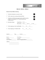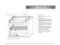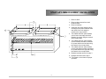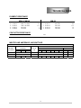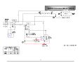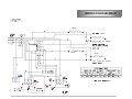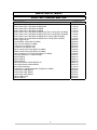
1
Service Manual for the Lang Models:
MM-24, MM-36, MM-48
Lang Manufacturing Company
6500 Merrill Creek Parkway
Phone: 1-800-224-5264 Fax: 1-425-349-2733
www.langworld.com
Everett, WA 98203
©Copyright 2000
TABLE OF CONTENTS
CHAPTER
PAGE
1.
TABLE OF CONTENTS .......................................................................1
2.
READ FIRST ........................................................................................2
3.
EQUIPMENT DESCRIPTION...............................................................4
4.
INSTALLATION ....................................................................................5
5.
START-UP ...........................................................................................7
6.
GENERAL OPERATION ......................................................................10
7.
SEQUENCE OF OPERATION .............................................................11
8.
TROUBLESHOOTING .........................................................................12
9.
TECHNICAL DATA...............................................................................13
10. WIRING DIAGRAMS ............................................................................14
11. PARTS LIST .........................................................................................16
1
IMPORTANT
READ FIRST
CAUTION:
EACH UNIT IS HEAVY. FOR SAFE HANDLING,
INSTALLER SHOULD OBTAIN HELP AS NEEDED, OR
EMPLOY APPROPRIATE MATERIALS HANDLING
EQUIPMENT (SUCH AS A FORKLIFT, DOLLY, OR
PALLET JACK) TO REMOVE THE UNIT FROM THE
SKID AND MOVE IT TO THE PLACE OF
INSTALLATION.
CAUTION:
ANY STAND, COUNTER OR OTHER DEVICE ON
WHICH MELTER WILL BE LOCATED MUST BE
DESIGNED TO SUPPORT THE WEIGHT OF THE
MELTER.
CAUTION:
SHIPPING STRAPS ARE UNDER TENSION AND CAN
SNAP BACK WHEN CUT.
THIS APPLIANCE MUST BE GROUNDED AT THE
TERMINAL PROVIDED. FAILURE TO GROUND THE
APPLIANCE COULD RESULT IN ELECTROCUTION
AND DEATH.
DANGER:
WARNING:
NOTICE:
NOTICE:
NOTICE:
CAUTION:
CAUTION:
INSTALLATION OF THE UNIT MUST BE DONE BY
PERSONNEL QUALIFIED TO WORK WITH
ELECTRICITY. IMPROPER INSTALLATION CAN
CAUSE INJURY TO PERSONNEL AND/OR DAMAGE
TO EQUIPMENT. UNIT MUST BE INSTALLED IN
ACCORDANCE WITH ALL APPLICABLE CODES.
The data plate is located at the lower front of the left
side of unit. The melter voltage, wattage, serial
number, wire size, and clearance specifications are
on the data plate. This information should be
carefully read and understood before proceeding
with the installation.
The installation of any components such as a vent
hood, grease extractors, fire extinguisher systems,
must conform to their applicable National, State and
locally recognized installation standards.
During the first few hours of operation you may
notice a small amount of smoke coming off the
melter, and a faint odor from the smoke. This is
normal for a new melter and will disappear after the
first few hours of use.
ALWAYS KEEP THE AREA NEAR THE APPLIANCE
FREE FROM COMBUSTIBLE MATERIALS.
KEEP FLOOR IN FRONT OF EQUIPMENT CLEAN
AND DRY. IF SPILLS OCCUR, CLEAN IMMEDIATELY,
TO AVOID THE DANGER OF SLIPS OR FALLS.
2
IMPORTANT
IMPORTANT
READ FIRST
WARNING:
KEEP WATER AND SOLUTIONS OUT OF CONTROLS.
NEVER SPRAY OR HOSE CONTROL CONSOLE,
ELECTRICAL CONNECTIONS, ETC.
CAUTION:
MOST CLEANERS ARE HARMFUL TO THE SKIN, EYES,
MUCOUS MEMBRANES AND CLOTHING.
PRECAUTIONS SHOULD BE TAKEN TO WEAR RUBBER
GLOVES, GOGGLES OR FACE SHIELD AND
PROTECTIVE CLOTHING. CAREFULLY READ THE
WARNING AND FOLLOW THE DIRECTIONS ON THE
LABEL OF THE CLEANER TO BE USED.
Service on this, or any other, LANG appliance must be
performed by qualified personnel only. Consult your
authorized service station directory or call the factory at
1-800-224-LANG (5264), or WWW.LANGWORLD.COM for
the service station nearest you.
BOTH HIGH AND LOW VOLTAGES ARE PRESENT
INSIDE THIS APPLIANCE WHEN THE UNIT IS
PLUGGED/WIRED INTO A LIVE RECEPTACLE. BEFORE
REPLACING ANY PARTS, DISCONNECT THE UNIT
FROM THE ELECTRIC POWER SUPPLY.
USE OF ANY REPLACEMENT PARTS OTHER THAN
THOSE SUPPLIED BY LANG OR THEIR AUTHORIZED
DISTRIBUTORS CAN CAUSE BODILY INJURY TO THE
OPERATOR AND DAMAGE TO THE EQUIPMENT AND
WILL VOID ALL WARRANTIES.
NOTICE:
WARNING:
CAUTION:
3
IMPORTANT
EQUIPMENT DESCRIPTION
ELECTRIC CHEESE MELTER
EXTERIOR
¾
The melter dimensions are 19.5” (49.5cm) High, 16.5” (42cm) Deep, 24”, 36”, 48” (61cm, 91cm,
122cm) wide dependent on the actual model number.
¾
The Sides, Bottom, and Rear wall are constructed stainless steel.
¾ The melter cavity is insulated with high temperature insulation for efficiency and reduced heat loss.
INTERIOR
¾
The interior dimension are 9.5” (24cm) High, 14.5” (37cm) Deep, 21.25”, 32”, 45.25” (54cm, 81.25cm,
115cm) wide dependent on the actual model number.
¾
The interior of the melter has one rack that can be placed in 4 different positions.
¾
The interior of the melter has a rack sensitive micro-switch for quick and easy activation.
CONTROLS
♦
AUTOMATIC
¾
Front two elements will only glow red when the rack sensitive micro-switch is activated. If there is
nothing on the rack the melter is in a standby mode with all three elements warm.
Note: With food on the rack the rear element should never turn red or get hot.
♦
CONTINUOUS
¾
Front two elements are on all the time.
Note: The Rear element should never turn red or get hot.
4
INSTALLATION
RECEIVING THE MELTER
Upon receipt, check for freight damage, both visible and concealed. Visible damage should be noted on the freight
bill at the time of delivery and signed by the carrier's agent. Concealed loss or damage means loss or damage, which
does not become apparent until the merchandise has been unpacked.
If concealed loss or damage is discovered upon unpacking, make a written request for inspection by the carrier's
agent within 15 days of delivery. All packing material should be kept for inspection.
Do not return damaged merchandise to Lang Manufacturing Company. File your claim with the carrier.
Prior to un-crating, move the melter as near its intended location as practical. The crating will help protect the unit
from the physical damage normally associated with moving it through hallways and doorways.
ELECTRICAL
Electrical service routing may be made through either of two 1 1/4 inch knockouts provided. One may be found
along the bottom edge of the back panel. The second knockout is located on the bottom of the unit.
Reference the Data Plate on the left side of the unit for amperage, voltage and phase requirements. Insure that the
power supply is sufficient to meet the units power needs.
Check your local or national electrical code for fuse or circuit breaker requirements.
PHASING
All model numbers MM-24 and MM-36 are shipped single phase.
MM-48 is shipped three phase and can be swapped to single phase by moving wire #3 to L1.
ELEMENT INSTALLATION
Elements for all electric model MM Cheesemelters are shipped, packaged separately, within the equipment shipping
crate.
These should be inspected upon opening of the shipping carton. If an element is found damaged or broken, notify
the Freight Company immediately. Reference manual section entitled "Receiving - Inspection and Claims,” request
an inspection and file a hidden damage claims with the carrier.
Contact Lang Manufacturing Company to order replacement elements. An invoice will be required by the Freight
Company to support the freight claim and reimbursement of costs related to the claim.
Installation of the elements is not warrantable expense. The installer or a qualified service company should
complete installation. Damage to elements or equipment resulting from incorrect or improper installation will be the
responsibility of the equipment owner or individual installing elements.
Elements installed in new equipment are warranted free of defects in material and workmanship, for a period of 90
days from installation of the equipment. Replacement elements are warranted for a period of 90 days from
installation.
5
INSTALLATION CONT’D
WALL MOUNT UNITS
Split the back into two pieces; note the pre-drilled holes in one panel. This is the wall mounting bracket.
Fasten the wall mounting bracket to the wall using pre-drilled holes. Use suitable lag screws or anchor fasteners to
secure panel to the wall with the off-set at the top. Make certain that the mounting bracket is level.
Remove the screws from the rear of the cheesemelter; screw the stainless steel portion of the back to the
cheesemelter with the off-set at the top.
Lift the cheesemelter and hang it on the wall mounted bracket.
Replace the screws around the edge of the back.
Observe minimum clearances at all times.
Must be mounted with 12 to 22 inches above the cooking surface.
Install the Heat Shield on the bottom of the unit.
This unit cannot be mounted above a broiler.
COUNTER TOP
Split the back into two pieces.
Remove the screws from the rear of the cheesemelter; screw the stainless steel portion of the back to the
cheesemelter with the off-set at the top.
Reinstall the two back halves together and replace the screws around the edge.
When installing on a counter the legs must be installed before using the unit, as they will provide the required
clearance for the bottom of the unit.
Place the unit in location, and level using leg adjustments.
Observe minimum clearances at all times.
6
START-UPS
MM-24 / MM-36 / MM-48
Electric Cheese Melter Start-Up
1. Verify that elements are correctly wired.
2. Verify connections at plug and terminal block.
3. Verify that on Wall-mount units that heat shield is in place
and there is a minimum of 22” between melter and
cooking surface.
4. Incoming Voltage:
Single Phase L1-L2_____
Three Phase
L1-L2_____ L2-L3_____ L3-L1_____
5. Verify amperage in Auto and Standby.
L1_____ L2_____ L3_____
6. Verify amperage in Constant mode.
L1_____ L2_____ L3_____
Model #_______
Date_______ Serial #________
Store #___________
Tech Name___________________
Contact_______________ Company _________________________
Store Phone #___________ Service Company Phone #______________
Address_____________________
______________________
______________________
7
START-UPS MM24 / 36 ELEMENT INSTALLATION
1. Remove Shelf
2. Remove three screws from each heater
bracket.
3. Remove brackets.
4. Install the rear quartz heater (white end
caps) to the power leads on both rear
sides of the unit using the ceramic wire
nuts provided.
5. The middle and front quartz heaters (red
or brown end caps) are wired together
(in series) using the ceramic wire nuts
provided.
6. The middle and front quartz heaters are
each connected to a power lead using
the ceramic wire nuts provided.
7. Replace brackets removed in step 3.
8. Replace shelf removed in step 1.
9. Turn Power on and check for proper
operation.
8
START-UPS MM48 ELEMENT INSTALLATION
1. Remove Shelf
2. Remove three screws from each
heater bracket.
3. Remove brackets.
4. Install the rear quartz heaters (white
end caps) to the power leads on both
rear sides of the unit using the
ceramic wire nuts provided.
5. The middle and front quartz heaters
(red or brown end caps) are wired
together (in series) using the ceramic
wire nuts provided.
6. The middle and front quartz heaters
(on the left side) are each connected
to a power lead on the left side using
the ceramic wire nuts provided.
7. The middle and front quartz heaters
(on the right side) are each connected
to a power lead on the right side using
the ceramic wire nuts provided.
8. Replace brackets removed in step 3.
9. Replace shelf removed in step 1.
10. Turn Power on and check for proper
operation.
9
GENERAL
GENERAL
The Lang Electric Cheesemelter can be used to poach, sauté and brown. In addition to melting cheese on
sandwiches, French onion soup, hot apple pie and casseroles, it may be used for finishing Italian, Mexican
and au gratin dishes utilizing less energy than conventional broilers.
The product is heated with infrared energy provided by quartz heaters. The rack is counterbalanced so that
maximum heat is supplied only when the product is placed in the rack.
Although the heating elements are not directly controlled to regulate heat, the exposure of the product to
heat is adjustable. Heat adjustment may be obtained by raising and lowering the rack position. The shelf
positions provide a choice of cooking positions for a variety of applications. The top position is very hot,
and can be used for quick browning and toasting, with the heat decreasing at each lower position.
In order to change positions, simply slide the rack in and out of the slots provided. Make sure that the end
of the rack engages the sliding mechanism located on the right front corner.
CONTROLS
Controls are located on the front panel and consist of the following items:
Power Switch - a toggle switch used to turn the unit on and off.
Heat Switch - this toggle switch allows the unit to be operated in either automatic or constant modes.
Automatic:
when selected with no product on the rack, the unit is in an idle condition.
Placing a product on the rack will energize the elements providing heat to the
product.
Constant:
when this mode is selected the elements are energized at all times whether or not
a product has been placed on the rack. This mode should be used during peak
times only, as it will shorten the life span of the elements.
Side Switch -
Allows the use of the Left side only, or Both sides. This switch is found on
Lang Model MM48 Cheesemelters only.
OPERATING DO's and DON'Ts
DO:
Insure all dishes placed in the cheesemelter are oven safe.
Pre-heat pans in the cheesemelter or on a stove.
Turn products halfway through cooking, as needed.
Use the unit in Automatic as much as possible, use Constant during peak periods.
DON'T:
Do not use the cheesemelter as a cooking or baking device, it is best suited for finishing dishes
immediately prior to serving.
Do not use the unit to heat or thaw chilled or frozen product.
Do not place aluminum foil on the rack or bottom shelf. This will reflect heat and expose
components to unnecessary high temperatures.
Do not move rack from one position to another without hand protection.
10
SEQUENCE OF OPERATION
AUTOMATIC MODE
Power switch to “ON” position.
208/240 VAC to Primary heater contactor coil.
Contactor energizes.
208/240 VAC to all three, Elements.
Elements warm up.
208/240 VAC to Rack sensitive micro switch.
Food is placed on rack.
Rack sensitive micro switch is closed.
208/240 VAC to Secondary heater contactor coil.
Contactor energizes.
208/240 VAC to Front two Elements only.
Front two elements heat up.
CONSTANT MODE
Power switch turned to on:
208/240 VAC to Primary heater contactor coil.
208/240 VAC to Secondary heater contactor coil.
Contactors energize.
208/240 VAC to Front two Elements.
Front two elements heat up.
11
TROUBLESHOOTING
Will not heat
PROBABLE CAUSE
CORRECTIVE ACTION
Incorrect voltage
¾
Confirm that correct voltage is coming to unit.
¾
Confirm that unit is phased correctly.
¾
Confirm that switch has 208/240 VAC to it.
¾
Check switch for proper operation.
¾
Confirm that contactor has 208/240 VAC to it.
¾
Check contactor for proper operation. (1023 Ω)
Defective Selector switch
¾
Check switch for normal operation.
Defective Element
¾
Confirm that elements are wired correctly.
¾
Confirm that element has 208/240 VAC to it.
¾
Check Element for continuity.
¾
Confirm that plunger rod can move up and down easily.
¾
Confirm that switch has 208/240 VAC to it.
¾
Check Switch for normal operation.
Defective Power Switch
Defective Contactor
Defective Rack Switch
12
TECHNICAL DATA
ELEMENT RESISTANCE
MM-24, MM-48
¾
¾
¾
¾
Part #
11160-15
11160-19
11160-16
11160-20
MM-36
Voltage
208V / 33 Ohms
104V / 08 Ohms
240 Volts
120 Volts
Amps
5.7
11.5
5
10
¾
¾
¾
¾
Part #
11160-17
11160-21
11160-18
11160-22
Voltage
208 Volts
104 Volts
240 Volts
120 Volts
Amps
8.6
17.3
7.5
15
CONTACTOR RESISTANCE
CONTACTOR
Part #
Coil
¾
30701-02
1023 Ω
2 Pole 208/240 Volt coil
MELTER LINE AMPERAGE, AND WATTAGE
ELECTRICAL DATA
MODEL
NUMBER
MM-24
MM-35
MM-48
THREE PHASE
LOADING
K.W. PER PHASE
L1-L2 L2-L3 L3-L1
SINGLE PHASE ONLY
SINGLE PHASE ONLY
2.4
2.4
0.0
TOTAL
K.W.
2.4
3.6
4.8
NOMINAL AMPS PER LING
THREE PHASE
SINGLE PAHSE
208 VOLT
240 VOLT
208V
240V
L1
L2
L3
L1
L2
L3
SINGLE PHASE ONLY
11.5
10.0
SINGLE PHASE ONLY
17.3
15.0
11.5 20.0 11.5 10.0 17.3 10.0
23.1
20.0
13
WIRING DIAGRAM MM-24 / MM-36
REAR
FRONT
MIDDLE
14
WIRING DIAGRAM MM-48
REAR
FRONT
MIDDLE
REAR
FRONT
MIDDLE
15
MM-24, MM-36, MM-48
ELECTRIC CHEESE MELTER
PART NO.
DESCRIPTION
Quartz Heater 208V 1200 Watts 2ft MM-24, 48
Quartz Heater 240V 1200 Watts 2ft MM-24, 48
Quartz Heater 208V 1800 Watts 3ft MM36
Quartz Heater 240V 1800 Watts 3ft MM36
Quartz Heater 104V 1200 Watts 2ft MM-24, 48 (Front 2 Only) (After D-30000)
Quartz Heater 120V 1200 Watts 2ft MM-24, 48 (Front 2 Only) (After D-30000)
Quartz Heater 104V 1800 Watts 3ft MM36 (Front 2 Only) (After D-30000)
Quartz Heater 120V 1800 Watts 3ft MM36 (Front 2 Only (After D-30000)
Switch Toggle On-Off
Terminal Block 3 Pole (After D-30000)
Relay 240 VAC (Before C-29999)
Contactor 3 Pole 208/240 VAC
Contactor 2 Pole 208/240 VAC
Starter Control Panel Lamp (Before C-29999)
Ballast Control Panel Lamp (Before C-29999)
Lamp Fluorescent 12” Control Panel (Before C-29999)
Pilot Light 208/240V 6” Lead Black Body
Rack for MM-24
Rack for MM-36
Rack for MM-48
Tube Guard Quartz Heaters MM-24, 48
Tube Guard Quartz Heaters MM-36
Micro Switch Assembly
Push Button to Toggle Switch Mod. Kit (Before C-29999)
Control Panel Label MM-24
Control Panel Label MM-36
Control Panel Label MM-48
Reflector MM-24, 48
Reflector MM-36
16
11160-15
11160-16
11160-17
11160-18
11160-19
11160-20
11160-21
11160-22
30303-06
30500-09
30600-02
30700-05
30701-02
31600-03
31600-04
31600-06
31601-01
50200-13
50200-14
50200-15
50201-03
50201-04
51100-12
60101-08
60700-02
60700-03
60700-04
60102-30
60102-04