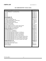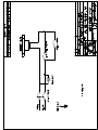
1
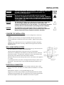
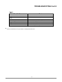
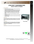
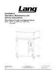
Installation, Operation, & Maintenance
Model: 236CM, 248CM, Gas Infrared Cheesemelter
Lang Manufacturing
Part # 2M-60803-02
Rev. C
10 Sunnen Drive,
Phone:314-678-6315 Fax: 314-781-2714
www.langworld.com
St. Louis, MO 63143
July 22, 2008
THE INFORMATION IN THIS MANUAL IS CRUCIAL AND MUST BE
RETAINED FOR FUTURE REFERENCE. READ, UNDERSTAND AND
FOLLOW THE INSTRUCTIONS AND WARNINGS CONTAINED IN THIS
MANUAL.
DANGER
POTENTIALLY HAZARDOUS SITUATION WHICH, IF NOT
AVOIDED, COULD RESULT IN DEATH.
WARNING
POTENTIALLY HAZARDOUS SITUATION WHICH, IF NOT
AVOIDED, COULD RESULT IN DEATH OR SERIOUS INJURY.
CAUTION
POTENTIALLY HAZARDOUS SITUATION WHICH, IF NOT
AVOIDED, MAY RESULT IN MINOR OR MODERATE INJURY.
NOTICE
Helpful operation and installation instructions and tips are
present.
FOR YOUR SAFETY
DO NOT STORE OR USE GASOLINE OR OTHER FLAMMABLE VAPORS
AND LIQUIDS IN THE VICINITY OF THIS OR ANY OTHER APPLIANCE.
WARNING: IMPROPER INSTALLATION, ADJUSTMENT, ALTERATION,
SERVICE OR MAINTENANCE CAN CAUSE PROPERTY DAMAGE, INJURY
OR DEATH. READ THE INSTALLATION, OPERATING AND MAINTENANCE
INSTRUCTIONS THOROUGHLY BEFORE INSTALLING OR SERVICING THIS
EQUIPMENT.
IF YOU SMELL GAS:
1. Shut off gas to the appliance
2. Extinguish any open flame.
3. If odor continues immediately call your dealer / installer or your fire department.
Lang Manufacturing
Part # 2M-60803-02
Rev. C
Model No:
Purchased From:
Serial No:
Location:
Date Purchased:
Date Installed:
Purchased Order No:
For Service Call:
10 Sunnen Drive,
Phone:314-678-6315 Fax: 314-781-2714
www.langworld.com
St. Louis, MO 63143
July 22, 2008
THE INFORMATION IN THIS MANUAL IS CRUCIAL AND MUST BE
RETAINED FOR FUTURE REFERENCE. READ, UNDERSTAND AND
FOLLOW THE INSTRUCTIONS AND WARNINGS CONTAINED IN THIS
MANUAL.
TABLE OF CONTENTS
CHAPTER
PAGE
TABLE OF CONTENTS ...................................................................................... 3
READ FIRST ........................................................................................................ 4
SAFETY PROCEDURES ..................................................................................... 6
EQUIPMENT DESCRIPTION ............................................................................. 7
UNPACKING........................................................................................................ 8
INSTALLATION .................................................................................................. 9
INITIAL START UP............................................................................................. 11
OPERATION ........................................................................................................ 12
MAINTENANCE & CLEANING......................................................................... 14
TROUBLE SHOOTING ....................................................................................... 16
PARTS LIST ......................................................................................................... 18
WIRING DIAGRAM ............................................................................................ 19
3
IMPORTANT
CAUTION
CAUTION
CAUTION
READ FIRST
IMPORTANT
THE UNIT IS EXTREMELY HEAVY. FOR SAFE HANDLING, INSTALLER
SHOULD OBTAIN HELP AS NEEDED, OR EMPLOY APPROPRIATE
MATERIALS HANDLING EQUIPMENT (SUCH AS A FORKLIFT, DOLLY, OR
PALLET JACK) TO REMOVE THE UNIT FROM THE SKID AND MOVE IT TO
THE PLACE OF INSTALLATION.
ANY STAND, COUNTER OR OTHER DEVICE ON WHICH THE UNIT WILL
BE LOCATED MUST BE DESIGNED TO SUPPORT THE WEIGHT OF THE
UNIT.
SHIPPING STRAPS ARE UNDER TENSION AND CAN SNAP BACK WHEN
CUT.
DANGER
THIS APPLIANCE MUST BE GROUNDED AT THE TERMINAL PROVIDED.
FAILURE TO GROUND THE APPLIANCE COULD RESULT IN
ELECTROCUTION AND DEATH.
WARNING
INSTALLATION OF THE UNIT MUST BE DONE BY PERSONNEL
QUALIFIED TO WORK WITH ELECTRICITY AND PLUMBING. IMPROPER
INSTALLATION CAN CAUSE INJURY TO PERSONNEL AND/OR DAMAGE
TO EQUIPMENT. UNIT MUST BE INSTALLED IN ACCORDANCE WITH ALL
APPLICABLE CODES.
NOTICE
The data plate is located on the left side of unit behind the control door.
The unit voltage, wattage, gas specifications, serial number, and
clearance specifications are on the data plate. This information should be
carefully read and understood before proceeding with the installation.
NOTICE
The installation of any components such as a vent hood, grease
extractors, fire extinguisher systems, must conform to their applicable
National, State and locally recognized installation standards.
NOTICE
Do not install the Cheesemelter over a Charbroiler or any other open
flame appliance.
NOTICE
During the first few hours of operation you may notice a small amount of
smoke coming from the unit, and a faint odor from the smoke. This is
normal for a new unit and will disappear after the first few hours of use.
ALWAYS KEEP THE AREA NEAR THE APPLIANCE FREE FROM
COMBUSTIBLE MATERIALS.
CAUTION
CAUTION
WARNING
CAUTION
KEEP FLOOR IN FRONT OF EQUIPMENT CLEAN AND DRY. IF SPILLS
OCCUR, CLEAN IMMEDIATELY, TO AVOID THE DANGER OF SLIPS OR
FALLS.
KEEP WATER AND SOLUTIONS OUT OF CONTROLS. NEVER SPRAY OR
HOSE CONTROL CONSOLE, ELECTRICAL CONNECTIONS, ETC.
MOST CLEANERS ARE HARMFUL TO THE SKIN, EYES, MUCOUS
MEMBRANES AND CLOTHING. PRECAUTIONS SHOULD BE TAKEN TO
WEAR RUBBER GLOVES, GOGGLES OR FACE SHIELD AND
PROTECTIVE CLOTHING. CAREFULLY READ THE WARNING AND
FOLLOW THE DIRECTIONS ON THE LABEL OF THE CLEANER TO BE
USED.
4
IMPORTANT
NOTICE
WARNING
CAUTION
READ FIRST
IMPORTANT
Service on this, or any other, LANG appliance must be performed by
qualified personnel only. Consult your LANG authorized service agent
directory or call the factory at 314-678-6315 or www.langworld.com For
the LANG service agent nearest you.
BOTH HIGH AND LOW VOLTAGES ARE PRESENT INSIDE THIS
APPLIANCE WHEN THE UNIT IS PLUGGED/WIRED INTO A LIVE
RECEPTACLE. BEFORE CLEANING, SERVICING OR REPLACING ANY
PARTS, DISCONNECT THE UNIT FROM THE ELECTRIC POWER SUPPLY.
USE OF ANY REPLACEMENT PARTS OTHER THAN THOSE SUPPLIED BY
LANG OR THEIR AUTHORIZED DISTRIBUTORS CAN CAUSE BODILY
INJURY TO THE OPERATOR AND DAMAGE TO THE EQUIPMENT AND
WILL VOID ALL WARRANTIES.
5
SAFETY PROCEDURES
Lockout Procedure
1.
2.
3.
4.
5.
6.
Announce lockout to other personnel.
Turn both heat and control power off at main panel.
Test lockout by turning power switch on and observing if fan(s) come on.
Check heater circuit with voltmeter.
Perform necessary repairs or tests.
Turn power on at main panel.
Announce unit is “on” to other personnel.
Safety Precautions
The Manufacturer, Lang Manufacturing, hereby disclaims any and all responsibility for injury, damage,
loss or other claim that may occur to person or property form improper alteration, modification, addition,
operation, maintenance or service, whether it be mechanical, electrical, fuel, operator motor or otherwise,
which may occur from such improper alteration, modification, addition, operation, maintenance or service
to this piece of equipment.
Safety Considerations
Your Lang Melter is manufactured to rigid standards. This equipment is N.S.F and ETL listed and meets
safety and sanitation standards.
The presence of safety equipment control and interlocks on an appliance and attendant components of
installation cannot in and of themselves, assure absolute safety of operation. Diligent, capable, well
trained operators and maintenance personnel, as well as proper programs of operation and maintenance,
are essential to the safe and reliable operation of this appliance.
A. The responsibility of the manufacturer is to supply suitable, comprehensive instructions and
recommendations for the operation and maintenance of the appliance.
B. Trained qualified and factory-authorized personnel must perform all operation, maintenance and
repair of these appliances. It is the responsibility of the owner / operator to ensure that this
happens.
C. A regular periodic program of cleaning, inspection and maintenance must be established and
comprehensive maintenance records maintained. It is the sole responsibility of the user to establish,
schedule and enforce the frequency and scope of these programs in keeping with recommended
practice and with due consideration given to actual operating conditions.
D. The appliance must be operated within the limits, which will not exceed the working limits of any
component within the appliance as a whole.
6
EQUIPMENT DESCRIPTION
Lang Model: 236CM, 248CM
Gas Infrared Cheesemelter
Exterior
The unit dimensions are 28” (71cm) High without legs, 21” (53cm) Deep, and
36”, 48” (91cm, 122cm,) Wide dependent on the actual model number.
The Sides, Bottom, and Rear wall are of constructed stainless steel.
The melter cavity is insulated with high temperature insulation for efficiency and
reduced heat loss.
Interior
The interior dimensions are 10” (25.4cm) High, 14½” (36.8cm) deep, and 33”, 45”
(83.8cm, 114.3cm) Wide.
The melter comes standard with one rack, which can be placed in four different
positions.
The melter has a rack sensitive micro-switch for a quick and easy activation.
Controls
Power Switch
Applies power to the unit for operation
Mode Switch
Sets the mode between Constant heat and Automatic
heat
Manual Gas Valve
Turns main gas valve on
Micro-Switch
Activates main burner when in Automatic Mode
7
UNPACKING
CAUTION
CAUTION
CAUTION
THE UNIT IS EXTREMELY HEAVY. FOR SAFE HANDLING, INSTALLER
SHOULD OBTAIN HELP AS NEEDED, OR EMPLOY APPROPRIATE
MATERIALS HANDLING EQUIPMENT (SUCH AS A FORKLIFT, DOLLY, OR
PALLET JACK) TO REMOVE THE UNIT FROM THE SKID AND MOVE IT TO
THE PLACE OF INSTALLATION.
ANY STAND, COUNTER OR OTHER DEVICE ON WHICH THE UNIT WILL
BE LOCATED MUST BE DESIGNED TO SUPPORT THE WEIGHT OF THE
UNIT.
SHIPPING STRAPS ARE UNDER TENSION AND CAN SNAP BACK WHEN
CUT.
Receiving the Unit
Upon receipt, check for freight damage, both visible and concealed. Visible
damage should be noted on the freight bill at the time of delivery and signed by the
carrier's agent. Concealed loss or damage means loss or damage, which does not
become apparent until the merchandise has been unpacked. If concealed loss or
damage is discovered upon unpacking, make a written request for inspection by the
carrier's agent within 15 days of delivery. All packing material should be kept for
inspection. Do not return damaged merchandise to Star Manufacturing
International. File your claim with the carrier.
Location
Prior to un-crating, move the unit as near its intended location as practical. The
crating will help protect the unit from the physical damage normally associated
with moving it through hallways and doorways.
Un-crating
The unit will arrive completely assembled inside a wood frame covered by
cardboard box and strapped to a skid. Remove the cardboard cover, cut the
straps and remove the wood frame.
8
INSTALLATION
DANGER
THIS APPLIANCE MUST BE GROUNDED AT THE TERMINAL PROVIDED.
FAILURE TO GROUND THE APPLIANCE COULD RESULT IN
ELECTROCUTION AND DEATH.
WARNING
INSTALLATION OF THE UNIT MUST BE DONE BY PERSONNEL
QUALIFIED TO WORK WITH ELECTRICITY AND PLUMBING. IMPROPER
INSTALLATION CAN CAUSE INJURY TO PERSONNEL AND/OR DAMAGE
TO EQUIPMENT. UNIT MUST BE INSTALLED IN ACCORDANCE WITH ALL
APPLICABLE CODES.
NOTICE
The data plate is located on the left side of unit behind the control door.
The unit voltage, wattage, gas specifications, serial number, and
clearance specifications are on the data plate. This information should be
carefully read and understood before proceeding with the installation.
NOTICE
The installation of any components such as a vent hood, grease
extractors, fire extinguisher systems, must conform to their applicable
National, State and locally recognized installation standards.
COUNTER TOP INSTALLATION
Legs must be installed on this appliance if it is to be configured as a counter top
model.
Attach the legs to the body by screwing the threaded stud of the leg into the nut
insert provided under each bottom corner of the machine. Tighten each leg with a
wrench.
Adjust the legs so that burners are level. Leg adjustment is made by turning the
adjustable foot at the bottom of each leg. Ensure that the leg does not turn while
adjusting the foot.
WALL HUNG INSTALLATIONS
The illustration, below, shows the connection points for the gas and electrical and
how the wall bracket is to connect to the Cheesemelter.
The heat shield is shipped in the 4-inch space at the rear of the machine.
Instructions for installing the heat shield are provided with the shield. Follow the
instructions carefully. It is important to remember to remove the knockouts from
the front edge of the machine after the heat shield is installed.
Minimum clearance from the cooking surface below to the bottom of this appliance
is 17 inches.
A wall hanging bracket is provided. It is shipped in the 4-inch space at the rear of
the machine. Attach the bracket to the wall studs then hang the machine on the
bracket.
ELECTRICAL CONNECTION
The electrical connection must be made in accordance with local codes or in the
absence of local codes with NFPA No. 70 latest edition (in Canada use: CAS STD.
C22.1).
Each appliance requires a 115 volt grounded supply at 1 amp.
Supply wire size must be large enough to carry the amperage load for the number
of appliances being installed. Wire size information can be found on the data plate.
The electrical diagram for the unit is behind the lower front access panel.
9
INSTALLATION CONT’D
GAS CONNECTION
This appliance must be installed under a ventilation hood. The installation of any
components such as vent hoods, grease extractors, fire and smoke detection
devices, or fire extinguisher systems, must conform to N.F.P.A Standard #96, latest
edition.
This appliance is manufactured for use with the type of gas indicated on the data
plate. Contact the factory if the gas type does not match that which is on the data
plate.
All gas connections must be in accordance with local codes and comply with the
National Fuel Gas Code ANSI Z223.1 latest edition.
Gas must be delivered to the appliance regulator at less than 1/2 pound of pressure
and less than 1/2 inch water column pressure drop.
The regulator on this appliance is set to 6 inches water column for natural gas and
10 inches water column for propane. A 1/8 inch NPT tap is provided on the main
manifold for checking regulator pressure.
When replacing the 1/8 inch plug in the main manifold a joint sealant that is
resistant to the action of liquid petroleum gas must be used.
The supply piping must be of sufficient size to provide 10,000 BTU/hr per foot of
Cheesemelter. A 1/2 inch NPT connection is provided at the lower right rear
corner.
A gas shut off valve must be installed to the appliance and located in an accessible
area. In the event of a significant drop in gas pressure, turn the shut off valve off
and contact your gas supplier.
This appliance and its individual shutoff valve must be disconnected from the gas
supply piping system during any pressure testing of that system at test pressures in
excess of 1/2 PSGI (3.45 kPA) and the appliance must be isolated from the gas
supply piping system by closing its individual manual shutoff valve during any
pressure testing of the gas supply system at test pressures equal to or less than 1/2
PSIG (3.45 kPA).
Test for gas leaks. Use a commercial leak detector or a soap and water solution.
NOTICE
Do not install the Cheesemelter over a Charbroiler or any other open
flame appliance.
VENTILATION AND CLEARANCES
Standard minimum clearance from combustible construction is as follows:
To prevent the function of this appliance from being affected by a reduced
atmospheric pressure, adequate make-up air in the kitchen should be provided to
replace the air taken out by the ventilating system.
6” from side
0” from back
4” from floor or 12” from high heat source
When mounting over a range top griddle or any other high heat source a bottom
clearance of 12” must be maintained and the heat shield (provided with all wall
mount units) must be installed. Failure to maintain this clearance and / or to install
the heat shield will the equipment warranty
10
INITIAL START UP
NOTICE
During the first few hours of operation you may notice a small amount of
smoke coming from the unit, and a faint odor from the smoke. This is
normal for a new unit and will disappear after the first few hours of use.
PRE-POWER ON
After the melter is connected to power and gas, prior to turning on, verify the
following:
•
The manual gas valve opens and closed freely.
•
The rack moves up and down freely
•
All packing material has been removed from the melter.
•
The melter has no gas leaks.
POWER ON & PILOT LIGHTING
Lighting Instructions:
The pilot burner must be lit with a match. Gas flows to the pilot as soon as all the
gas valves are turned On. Be aware that it may take a few minutes, on new
installations, for gas to be present at the pilot burner, as air must first be purged from
the gas line.
The pilot burner will remain lit even if the Cheese Melter is switched to Off.
Once the pilot burner is lit, allow one minute for pilot to heat enough to enable the
main burner to light.
Set the Constant - Auto switch to Constant and allow the machine to run for five
minutes. A small amount of smoke may emanate from the machine as it heats, do
not be alarmed as this is a normal condition related to the burning off of oils
associated with the manufacturing process. Set the Constant - Auto switch to Auto
to place the machine into the Stand-by mode.
Note: Electrical power is required to safely operate this cheesemelter. This unit will not
operate in the event of a power failure, but pilot gas will continue.
TO SHUTDOWN UNIT
Turn off electrical supply to the unit and shut off the gas supply manual valve located in the
gas supply line at the bottom of the unit at the rear gas entry.
11
OPERATION
CAUTION
ALWAYS KEEP THE AREA NEAR THE APPLIANCE FREE
FROM COMBUSTIBLE MATERIALS.
CAUTION
KEEP FLOOR IN FRONT OF EQUIPMENT CLEAN AND DRY. IF
SPILLS OCCUR, CLEAN IMMEDIATELY, TO AVOID THE
DANGER OF SLIPS OR FALLS.
GENERAL
The Lang gas melter can be used to poach, sauté and brown. In addition to
melting cheese on sandwiches, French onion soup, hot apple pie and
casseroles, it may be used for finishing Italian, Mexican and au gratin dishes
utilizing less energy than conventional broilers.
The product is heated with 1650°F of infrared heat, which penetrates the
product preventing burning and scorching. The rack is counterbalanced so that
maximum heat is supplied only when the product is placed in the rack.
Although the heating elements are not directly controlled to regulate heat, the
exposure of the product to heat is adjustable. Heat adjustment may be obtained
by raising and lowering the rack position. The shelf positions provide a choice
of cooking positions for a variety of applications. The top position is very hot,
and can be used for quick browning and toasting, with the heat decreasing at
each lower position.
In order to change positions, simply slide the rack in and out of the slots
provided. Make sure that the end of the rack engages the sliding mechanism
located on the right front corner.
CONTROLS
There are very few controls that operate the gas cheese melter. Below is a list
of the various components with a description of their purpose.
Power Switch
Turns the unit On and Off.
Constant /
Auto Switch
When set to Constant, the burner(s) will light and
stay on. When set to AUTO, the burner(s) will light
whenever a product is placed onto the Tilting
Product Rack.
This valve turns off the flow of gas to the burner(s).
Once the machine is installed, this valve need not be
turned off as the POWER SWITCH should be
utilized to shut the machine down. The manual gas
valve cannot be used to regulate the heat output
from the burner(s), it must be full ON or full OFF.
The Tilting Product Rack is used to adjust the
amount of heat a product is exposed to and to start
the burner(s) when the machine is placed into the
Auto mode. Raising the tilting product rack
increases the heat on the product while lower the
rack decreases the heat.
Manual Gas Valve
Tilting Product Rack
12
OPERATION Cont’d
OPERATING DO’S AND DON’TS
DO:
Insure all dishes placed in the melter are oven safe.
Pre-heat pans in the melter or on a stove.
Turn products halfway through cooking, as needed.
Use the unit in Automatic as much as possible, use Constant during peak periods.
DON’TS
Do not use the melter as a cooking or baking device; it is best suited for finishing
dishes immediately prior to serving.
Do not use the unit to heat or thaw chilled or frozen product.
Do not place aluminum foil on the rack or bottom shelf. This will reflect heat and
expose components to unnecessary high temperatures.
Do not move rack from one position to another without hand protection.
13
MAINTENANCE & CLEANING
WARNING
KEEP WATER AND SOLUTIONS OUT OF CONTROLS. NEVER SPRAY OR
HOSE CONTROL CONSOLE, ELECTRICAL CONNECTIONS, ETC.
CAUTION
MOST CLEANERS ARE HARMFUL TO THE SKIN, EYES, MUCOUS
MEMBRANES AND CLOTHING. PRECAUTIONS SHOULD BE TAKEN TO
WEAR RUBBER GLOVES, GOGGLES OR FACE SHIELD AND
PROTECTIVE CLOTHING. CAREFULLY READ THE WARNING AND
FOLLOW THE DIRECTIONS ON THE LABEL OF THE CLEANER TO BE
USED.
CLEANING
The unit should be thoroughly cleaned once a day to insure against accumulation of
foreign material.
•
•
•
•
•
•
•
Always start with the unit cold & disconnect from its electrical source.
The stainless exterior can easily be cleaned using stainless steel
cleaner
Always follow the cleaner manufacturer's instructions when using any
cleaner.
Care should be taken to prevent caustic cleaning compounds from
coming in contact with the blower wheel.
The oven racks, rack slides, and interior may be cleaned using oven
cleaner.
Discoloration or heat tint may be removed using a Carbon Release
oven cleaner.
The oven interior should be cleaned using a mild soap and a non-metal
scouring pad. DO NOT use caustic cleaners.
Always apply these cleaners when the oven is cold and rub in
the direction of the metal's grain.
MAIN BURNER ACCESS
The main burner is removed through the top of the machine.
Remove the stainless steel top-front first by removing six sheet metal screws from
the ends.
Remove the entire top assembly by removing several sheet metal screws along the
edge of the top.
Remove the gas line from the burner at the compression fitting on the orifice.
Remove the two nuts at the opposite end of the burner from the orifice.
Lift the main burner from the machine.
MAIN BURNER ORIFICE ACCESS
The main burner orifice can be access without taking the burner from the machine.
Remove the stainless steel top-front first by removing six sheet metal screws from
the ends.
Remove the entire top assembly by removing several sheet metal screws along the
edge of the top.
Remove the gas line from the burner at the compression fitting at the orifice.
Unscrew the orifice fitting from the burner.
14
MAINTENANCE & CLEANING Cont’d
PILOT BURNER ADJUSTMENT
Pilot flame adjustment is accomplished at the brass tube fitting on the main
manifold.
The brass fitting located between the regulator and the solenoid valve which has the
1/8 inch tube connected to it is the adjuster.
Turn the hex head screw clockwise to shorten the pilot flame, and counterclockwise
to lengthen the pilot flame.
• The pilot must light the main burner within 5 seconds of gas being available at
the burner tiles (listen for the solenoid valve to open).
• The pilot must light the main burner without snuffing itself out.
• The pilot must continue to burn during an extended continuos operation of the
main burner.
RACK SWITCH ADJUSTMENT
The rack switch is located at the extreme right of the control compartment.
The Tilting Product Rack should energize the tilt switch at the mid-point in its travel.
To adjust the switch, bend the actuator arm.
15
TROUBLESHOOTING
Symptoms
What follows is a chart of Symptoms, Possible Causes, and Remedy’s to aid in
diagnosing faults with the unit.
Refer to the Symptoms column to locate the type of failure then to the Possible
Cause for the items to be checked. On the following pages is a chart with the
possible causes and the test to properly identify the problem.
Always start with the unit cold & disconnect from its
electrical source before cleaning or servicing.
SYMPTOM
Unit will not come on
POSSIBLE CAUSE
•
•
•
Defective outlet
Tripped Circuit Breaker
Defective Power Switch
• Plugged orifice
• Incorrect water column
• Defective regulator
• Defective pilot valve
Burner will not light
• Auto / Constant switch in incorrect position.
• Defective regulator
• Plugged main orifice
• Incorrect water column
• Defective solenoid valve
• Low pilot
• No gas to unit
• Defective tile assembly
Service on this, or any other, LANG appliance must be performed by
NOTICE
qualified personnel only. Consult your authorized service station
directory or call the factory at 314-678-6315, or www.langworld.com
For the service agent nearest you.
BOTH
HIGH AND LOW VOLTAGES ARE PRESENT INSIDE THIS
WARNING
APPLIANCE WHEN THE UNIT IS PLUGGED/WIRED INTO A LIVE
RECEPTACLE. BEFORE REPLACING ANY PARTS, DISCONNECT THE
UNIT FROM THE ELECTRIC POWER SUPPLY.
USE OF ANY REPLACEMENT PARTS OTHER THAN THOSE SUPPLIED BY
CAUTION
LANG OR THEIR AUTHORIZED DISTRIBUTORS CAN CAUSE BODILY
INJURY TO THE OPERATOR AND DAMAGE TO THE EQUIPMENT AND
WILL VOID ALL WARRANTIES.
Pilot will not light
16
TROUBLESHOOTING Cont’d
TEST
Possible Cause
Tripped Circuit Breaker
Defective Power Switch, Constant / Auto
switch
Defective Power Cord
Defective Regulator
Plugged Orifice
Faulty Solenoid Valve
Low Pilot
Test
• Reset Circuit breaker and re-test
• Check switch for normal operation
•
•
•
•
•
Check Power cord for continuity*
Check unit for proper Water Column*
Clean orifice*
Check Coil for 120V*
Confirm that pilot is steady and about 1” on both sides.
* A factory authorized service representative should perform this work.
17
PARTS LIST
July 22, 2008, Rev. C
GAS CHEESE MELETER: 236CM & 248CM
DESCRIPTION
PART NO.
Switch Toggle On-Off
Pilot Light 208/240V 6” Lead Black Body
Rack, 2ft
Rack, 3ft
Rack, 4ft
Rack, 5ft
Spring Regulator LP
Spring Regulator NG
Micro Switch Assembly
Pilot Burner Assembly Mod. Kit
Valve Manual Main Burner, 4ft & 5ft Units
Valve Manual Gas Pilot Burner
Valve Manual Main Burner, 3ft Units
Magnetic Catch w/Strike
Knob Gas On-Off Chrome
Infrared Gas Burner 15 5/16” Long, 2ft, 4ft & 5ft Units
Infrared Gas Burner 26 7/8” Long, 3ft & 5ft Units
Manifold Gas Melter, 3ft, 4ft & 5ft Units
Manifold Gas Melter, 4ft & 5ft Units
Pilot Burner Assembly
Orifice Pilot Burner .010 DRL LP
Orifice Pilot Burner .021 DRL NG
Orifice Gas Spud #42 DRL NG 30k for 26 7/8” Burner
Orifice Gas Spud #48 DRL NG 20k for 15 5/6” Burner
Orifice Gas Spud #52 DRL LP 30k for 26 7/8” Burner
Orifice Gas Spud #55 DRL LP 20k for 15 5/6” Burner
Orifice Gas Spud #45 DRL NG for 15 5/16” Burner (Chili’s Only)
Orifice Gas Spud #38 DRL NG for 26 7/8” Burner (Chili’s Only)
Orifice Gas Spud #54 DRL LP for 15 5/16” Burner (Chili’s Only)
Orifice Gas Spud #50 DRL LP for 26 7/8” Burner (Chili’s Only)
Regulator Gas Set 6” NG
Regulator Gas Set 10” LP
Valve Solenoid Gas 120 VAC
Flame Switch 24” Gas Grid, 236CM
2E-30303-06
2J-31601-01
2B-50200-13
2B-50200-14
2B-50200-15
2B-50200-29
2P-51001-10
OB-51001-11
J9-51100-12
J9-60101-18
2V-70402-05
2V-70402-06
2V-70402-07
2C-9788
2R-70701-43
2F-80005-01
2F-80005-02
2K-80100-10
2K-80100-11
2J-80201-20
2A-80401-09
2A-80401-11
2A-80404-03
2A-80404-09
2A-80404-13
2A-80404-16
2A-80404-23
2A-80404-24
2A-80404-27
2A-80404-28
2V-80501-01
2V-80501-03
2V-80502-01
NLA
Drip Pan Assy 3’
Drip Pan Assy 4’
J9-GM-175
J9-GM-176
ETL File 52501
18
STAR INTERNATIONAL HOLDINGS INC. COMPANY
Star - Holman - Lang - Wells - Bloomfield - Toastmaster
10 Sunnen Drive, St. Louis, MO 63143 U.S.A.
(314) 678-6303
www.star-mfg.com