1
OPERATION & SERVICE MANUAL
Model: YM9000
Central Monitoring System (CMS)
Mediana Co., Ltd.
Wonju Medical Industry Park, 1650-1 Donghwa-ri,
Munmak-eup, Wonju-si, Gangwon-do, Korea
Tel: (82) 33 742 5407 Fax: (82) 33 742 5483
YM9000 Operation & Service Manual
Part Number-Revision: A7035-0 (1205)
Printed in Korea
Copyright © 2003-2005 Mediana. All rights reserved.
ABOUT THIS MANUAL
Notice
This document contains proprietary information which is protected by copyright. All Rights Reserved.
Reproduction, adaptation, or translation without prior written permission is prohibited, except as allowed
under the copyright laws.
Warranty
The information contained in this document is subject to change without notice. Mediana makes no
warranty of any kind with regard to this material, including, but not limited to, the implied warranties or
merchantability and fitness for a particular purpose. Mediana shall not be liable for errors contained herein
or for incidental or consequential damages in connection with the furnishing, performance, or use of this
material.
Copyright
Copyright © MEDIANA Co., Ltd. 2003-2005
Revision/Printing History
New editions of this document incorporate all material updated since the previous edition. Update packages
may be issued between editions and contain replacement and additional pages to be merged by a revision
date at the bottom of the page. Pages that are rearranged due to changes on a previous page are not
considered revised.
The documentation printing date and part number indicate its current edition. The printing date changes
when a new edition is printed. (Minor corrections and updates that are incorporated at reprint do not cause
the date to change.) The document part number changes when extensive technical changes are incorporated.
ii
CMS OPERATION & SERVICE MANUAL
SOFTWARE LICENSE TERMS
ATTENTION: USE OF THE SOFTWARE IS SUBJECT TO THE Mediana Co., Ltd. SOFTWARE
LICENCE TERMS SET FORTH BELOW. USING SOFTWARE INDICATES YOUR
ACCEPTANCE OF THESE LICENSE TERMS. IF YOU DO NOT ACCEPT THESE LICENSE
TERMS, YOU MAY RETURN THE SOFTWARE FOR A FULL REFUND.
The following License Terms govern your use of the accompanying Software unless you have a
separate signed agreement with Mediana Co., Ltd.
License Grant: Mediana Co., Ltd. grants you a license to Use one copy of the software. “Use” means
storing, loading, installing, executing or displaying the Software. You may not modify the Software or
disable any licensing or control feature of the Software. If the Software is licensed for “concurrent use”, you
may not allow than the maximum number of authorized users to Use the Software concurrently.
Ownership: The Software is owned and copyrighted by Mediana Co., Ltd. or its third party suppliers. Your
license confers no title to, or ownership in, the Software and is not a sale of any rights in the Software.
Mediana Co., Ltd.’s third party suppliers may protect their rights in the event of any violation of these
License Terms.
Copies and Adaptations: You may not disassemble or decompile the Software for archival purpose or
when copying or adaptation is an essential step in the authorized Use of the Software. You must reproduce all
copyright notices in the original Software on all copies or adaptations. You may not copy the Software onto
any public network.
No Disassembly or Decryption: You may not disassemble or decompile the Software unless Mediana
Co., Ltd.’s prior written consents are obtained. In some jurisdictions, Mediana Co., Ltd.’s consent may not be
required for limited disassembly or decompilation. Upon request, you will provide Mediana Co., Ltd. with
reasonably detailed information regarding any disassembly or decompilation. You may not decrypt the
Software unless decryption is a necessary part of the operation of the Software.
Transfer: Your license will automatically terminate upon transfer of the Software. Upon transfer, you must
deliver the Software, including any copies and related documentation, to the transferee. The transfers must
accept these License Terms as a condition to the transfer.
Termination: Mediana Co., Ltd. may terminate your license upon notice for failure to comply with any of
these License Terms. Upon termination, you must immediately destroy the Software, together with all copies,
adaptations and merged portion in any form.
Export Requirements: You may not export or re-export the Software or any copy or adaptation in
violation of any applicable laws or regulation.
CMS OPERATION & SERVICE MANUAL
iii
This page is intentionally left blank.
iv
CMS OPERATION & SERVICE MANUAL
Contents
CONTENTS
ABOUT THIS MANUAL................................................................................................................................................ii
SOFTWARE LICENSE TERMS..................................................................................................................................iii
INTRODUCTION ...........................................................................................................................................................1
YM9000 Central Monitoring System (CMS) Overview............................................................................................1
Intended use...............................................................................................................................................................1
Features......................................................................................................................................................................1
System Configuration ................................................................................................................................................2
SAFETY INFORMATION.............................................................................................................................................3
Text Conventions .......................................................................................................................................................3
Warnings ....................................................................................................................................................................3
Cautions .....................................................................................................................................................................4
INSTALLATION.............................................................................................................................................................5
List of Components....................................................................................................................................................5
Environmental Facility ..............................................................................................................................................5
System Installation.....................................................................................................................................................6
Central System Setting.......................................................................................................................................6
Beside Station Settings ......................................................................................................................................9
Software Installation................................................................................................................................................10
Applications Software Installation...................................................................................................................10
Initial Installation.............................................................................................................................................15
OPERATION .................................................................................................................................................................19
Start-up ....................................................................................................................................................................19
Main Screen.............................................................................................................................................................21
Display Configuration......................................................................................................................................22
Symbols and Controls......................................................................................................................................22
Setup Window..........................................................................................................................................................23
Wave Settings ..................................................................................................................................................23
Position Change ...............................................................................................................................................23
Sweep Speed....................................................................................................................................................23
Current Monitor Status ....................................................................................................................................24
Patient Information ..........................................................................................................................................24
Recording Settings...........................................................................................................................................24
Configuration...................................................................................................................................................24
Patient Window........................................................................................................................................................29
Patient Data Review Window ..................................................................................................................................30
Trend Review...................................................................................................................................................30
Wave Review ...................................................................................................................................................33
Alarm Indications ....................................................................................................................................................37
Alarm Silence ..................................................................................................................................................37
Alarm Suspend.................................................................................................................................................37
Recording.........................................................................................................................................................38
Alarm ...............................................................................................................................................................41
Record..............................................................................................................................................................41
CMS OPERATION & SERVICE MANUAL
v
Contents
Patient Window................................................................................................................................................41
Setup Window..................................................................................................................................................42
Patient Data Window .......................................................................................................................................44
QUICK INSTALLATION & START-UP GUIDE .....................................................................................................47
Hardware installation...............................................................................................................................................47
Software installation ................................................................................................................................................47
Start-up & Operation ...............................................................................................................................................47
MAINTENANCE & TROUBLESHOOTING ............................................................................................................49
Maintenance.............................................................................................................................................................49
Cleaning...........................................................................................................................................................49
Periodic Safety Checks ....................................................................................................................................49
Replacement of Recorder Paper.......................................................................................................................50
Checking Software Version..............................................................................................................................50
Troubleshooting .......................................................................................................................................................51
Operator Troubleshooting ................................................................................................................................51
Error and Status Messages ...............................................................................................................................52
SPECIFICATIONS & ACCESSORIES ......................................................................................................................55
Specifications...........................................................................................................................................................55
List of Accessories Available ...................................................................................................................................58
vi
CMS OPERATION & SERVICE MANUAL
Contents
Figures
Figure 1. YM9000 CMS Overview .........................................................................................................................................2
Figure 2. CMS Computer (PC) Settings.................................................................................................................................6
Figure 3. HUB (16 port) Front panel.....................................................................................................................................7
Figure 4. HUB (16 port) Rear panel......................................................................................................................................7
Figure 5. Isolation Transformer Settings ...............................................................................................................................8
Figure 6. External Thermal Recorder Settings.......................................................................................................................8
Figure 7. Installation Window..............................................................................................................................................10
Figure 8. Select Install Folder Window................................................................................................................................11
Figure 9. Installation Proceeding Window...........................................................................................................................11
Figure 10. Database Initialization Proceeding Window ......................................................................................................12
Figure 11. Lock-key Driver Installation Window .................................................................................................................12
Figure 12. Lock-key Driver Installation Complete Window.................................................................................................13
Figure 13. Data Access Components License Agreement Window.......................................................................................13
Figure 14. MS Data Access Components Install Window ....................................................................................................14
Figure 15. MS Data Access Components Install Window ....................................................................................................14
Figure 16. System Restart Window.......................................................................................................................................15
Figure 17. Installation Complete Window............................................................................................................................15
Figure 18. Installation of “Data access objects” Window ...................................................................................................15
Figure 19. Self-Test Finish Display......................................................................................................................................16
Figure 20. Program Initial Display......................................................................................................................................16
Figure 21. Password Window for Initial Installation ...........................................................................................................17
Figure 22. Initial Installation Window .................................................................................................................................17
Figure 23. Self-Test Finish Display......................................................................................................................................19
Figure 24. Program Initial Display......................................................................................................................................20
Figure 25. Main Screen Display ..........................................................................................................................................21
Figure 26. Setup Window Display........................................................................................................................................23
Figure 27. Patient Management Access Window Display ....................................................................................................24
Figure 28. Patient Management Window Display................................................................................................................24
Figure 29. System Configuration Access Window Display...................................................................................................26
Figure 30. System Configuration Window Display ..............................................................................................................26
Figure 31. Date/Time Message Display ...............................................................................................................................27
Figure 32. Shutdown/Restart Message Display ...................................................................................................................28
Figure 33. Patient Window Display .....................................................................................................................................29
Figure 34. Trend Review Display.........................................................................................................................................30
Figure 35. NIBP Graphical Trend Display Format..............................................................................................................31
Figure 36. Wave Review Display..........................................................................................................................................33
Figure 37. Alarm Review Display ........................................................................................................................................35
Figure 38. One–Shot Printout..............................................................................................................................................38
Figure 39. Trend Review Report ..........................................................................................................................................39
Figure 40. Alarm Review Report..........................................................................................................................................40
Figure 41. Wave Review Report ...........................................................................................................................................40
Figure 42. Replacement of Recorder Paper .........................................................................................................................50
Tables
Table 1. Bed Setting Codes.....................................................................................................................................................9
Table 2. Display Color Identification...................................................................................................................................22
Table 3. YM9000 CMS Controls...........................................................................................................................................22
Table 4. Troubleshooting .....................................................................................................................................................51
Table 5. Error Messages ......................................................................................................................................................53
CMS OPERATION & SERVICE MANUAL
vii
Contents
This page is intentionally left blank.
viii
CMS OPERATION & SERVICE MANUAL
Introduction
INTRODUCTION
YM9000 Central Monitoring System (CMS) Overview
The YM9000 Central Monitoring System (CMS) represents a significant advance in patient monitoring
through the integration of a wide range of functionality into a single, standard Microsoft Windows 2000 TM
professional version based Personal Computer. The YM9000 Central Monitoring System (CMS) combines
the features of a central monitor – multi-patient waveform and parameter display, alarm annunciation – with
the YM9000 Central Monitoring System (CMS) patient data review of a clinical review station to meet the
diverse needs of today's clinical environment.
The YM9000 Central Monitoring System (CMS) also represents advances in monitoring convenience,
flexibility, and ease-of-use. Display formats, monitoring controls, alarm response, and patient data
presentation are easily configured to suit user preferences and optimize user performance. The YM9000
Central Monitoring System (CMS) will be referred to as the YM9000 CMS throughout this manual.
Intended use
The intended use of the YM9000 CMS is to display physiologic waves, parameters, and trends, format data
for strip chart recordings and printings, and provide the annunciation of alarms from other networked medical
devices at a centralized location. The YM9000 CMS provides for the retrospective review of alarms,
physiologic waves and parameters from its database.
Features
The YM9000 CMS includes a wide range of features that can be easily configured to suit the needs and
preferences of specific clinical applications. Access to these features is made with a point-and-click mouse.
Simply move the mouse pointer to a labeled application button and click. The button's application is
immediately displayed on the screen. A keyboard is also provided for entering and changing patient data and
other information. The Center Monitoring System provides real-time waveform monitoring for up to 16
patients being monitored by patient monitor on the system’s Local Area Network (LAN). The standard
Center Monitoring System includes the following features:
The CMS for viewing real-time patient data and annunciation of alarms from bedside patient
monitor.
The CMS can review for up to 48 hours for stored patient monitoring data, waveforms and alarm
events.
Main Screen for displaying real-time waves and parameters for up to 8 or 16 patients and separate
Patient Window for viewing detailed real-time or stored data for individual patients.
<YM9000 CMS Window Display Capability>
Main Screen: Up to 8 beds or up to 16 beds
Patient Window: selectable monitor, with 4 waveforms shown
Patient Data Review Window: Trend Review, Wave Review, Alarm Review, bed selectable, data
recording, wave selectable, scroll capability, trend scale (time interval) user-selectable, event list,
tabular trend list.
Setup Window: wave setting, position setting, wave sweep speed setting, current monitor settings,
date/time setting, patient information, recording setting, and system configuration access.
CMS OPERATION & SERVICE MANUAL
1
Introduction
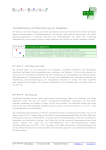
System Configuration
<YM9000 CMS configuration>
Operation
& Service
Manual
Isolation Transformer
YM9000 CMS
Application Software
Operation
& Service
Manual
Lock-Key
MEDIANA
LAN cable
Laser Printer
External Thermal
Recorder
HUB
PC
...
Patient Monitors
Figure 1. YM9000 CMS Overview
The YM9000 CMS consists of:
- YM9000 CMS application software CD
- Lock-key for Application software
- YM9000 Recorder System (External thermal recorder)
- (Option) Hub (16port) for connecting up to 8 monitors to a single CMS
- (Option) Hub (24port) for connecting up to 16 monitors to a CMS.
- (Option) LAN cables.
- (Option) PC for 8 bed CMS with Windows 2000 professional version
- (minimum Pentium 4 2.0GHz, minimum RAM 512Mbyte, 1280×1024 Graphic Card, External
Speaker, Sound card.(Option) PC for 16 bed CMS with Windows 2000 professional version
(minimum Xeon 2.4GHz, minimum RAM 1 G byte, 1280×1024 Graphic Card, External Speaker,
Sound Card)
- (Option) Isolation Transformer
- (Option) Flat panel PC monitor or CRT monitor (minimum 17 inches)
- (Option) LaserJet printer
2
CMS OPERATION & SERVICE MANUAL
Safety Information
SAFETY INFORMATION
Text Conventions
The following conventions for Notes, Cautions, and Warnings are used in this manual.
NOTE
NOTE: A Note calls attention to an important point in the text
CAUTION: A Caution calls attention to a condition or possible situation that could
damage or destroy the product or the user’s work.
WARNING: A Warning calls attention to a condition or possible situation that could
cause injury to the user and/or patient.
Warnings
WARNING: The PC that supports hyper threading must be turned the function
off for proper installation. Set the bios to turn off the hyper threading function
before boot. Follow the instructions in the PC manual how to set the bios.
WARNING: Explosion hazard. Do not use the CMS or the bedside monitor in the
presence of flammable anesthetics.
WARNING: Electric shock hazard. External covers and panels are to be removed only
by qualified service personnel. There are no user-serviceable parts inside.
WARNING: The components of the YM9000 CMS are intended only as an adjunct in
patient assessment. The system must be used in conjunction with clinical signs and
symptoms.
WARNING: Do not expose any components of the YM9000 CMS to extreme moisture
levels such as rain. Such exposure may cause incorrect or inaccurate performance, or
device failure during or after exposure.
WARNING: Patient safety could be compromised if the CMS is used as a personal
computer while patients are being monitored. The CMS is to be used for patient
monitoring only.
WARNING: The YM9000 CMS is intended to monitor patients. It is not a diagnostic
device. Any alarm or abnormal indication displayed at the CMS should be reviewed by
qualified medical personnel.
WARNING: System default, date, and time settings are selected and set by the system
administrator. For optimal patient safety, system default, date, and time settings should
be reviewed periodically.
WARNING: know the audible alarm silence duration before temporarily silencing any
audible alarm at the CMS. Do not silence audible alarms at the CMS or at the bedside
monitor or decrease their volume if patient safety could be compromised.
WARNING: When turning off or restarting the PC, you must follow proper ‘shut down’
instruction (refer to Operation section). If the PC abnormally shuts down, the YM9000
database may be lost and the system would not perform properly.
CMS OPERATION & SERVICE MANUAL
3
Safety Information
Cautions
CAUTION: Do not immerse any component of the CMS in liquid or use caustic or
abrasive cleaners. Do not spray or pour any liquid on the CMS or its accessories. Do not
allow any liquid to come in contact with the power connector, controls, or switches. Do
not allow any liquid to penetrate connectors or openings in the chassis.
CAUTION: Do not put the computer inside a cabinet or other closed space where air
cannot freely flow around these components.
CAUTION: The CMS is not to be used in mobile environments.
Do not use any components of the YM9000 CMS that are damaged.
CAUTION: The CMS displays the waveforms and numeric data of the patient monitor.
At setup of a bedside monitor with the patient monitor, verify the monitor is set to the
desired operation before using the bedside monitor for patient monitoring.
CAUTION: CMS is to be operated by qualified personnel only. Before use, carefully
read this manual, all precautionary information, and specifications for the patient
monitor and accessories. The user must check that the equipment functions safely and
see that it is in proper working condition before being used.
4
CMS OPERATION & SERVICE MANUAL
Installation
INSTALLATION
The YM9000 CMS consists of medical software executing on a standard Personal Computer running the
Windows 2000™ professional version Operating System.
WARNING: The PC that supports hyper threading must be turned the function off
for proper installation. Set the bios to turn off the hyper threading function before
boot. Follow the instructions in the PC manual how to set the bios.
WARNING: Installation and setup must be performed by a Mediana service
representative or service personnel in user’s institute.
CAUTION: The YM9000 CMS is not suitable for installation in the Patient Care Vicinity
(Patient Environment).
List of Components
Each YM9000 CMS includes the following standard components:
- YM9000 CMS application software CD
- Lock-key for Application software
- External Thermal Recorder
- Operation & Service Manual
The following optional components are also available:
- HUB (e.g. 16port, 24port)
- Isolation Transformer
- LAN Cable
- PC (e.g. HP Pavilion t112k or Intel Xeon, 2.0GHz with Window 2000 professional version O/S)
- PC Monitor (Size: 17 inch or more, Resolution: 1280×1024)
- Laser Printer (e.g. HP Laser Printer)
NOTE
For more information about components and accessories available, refer to the
Specification & Accessories section and contact your local Mediana sales representative.
NOTE
The components of the CMS must comply with electrical safety, reliability and
electromagnetic compatibility as intended as a whole system according to the safety and
regulatory requirements in the country of use.
The following components for the CMS configuration may be obtained from local
suppliers provided that the components conform to electrical safety, reliability and/or
electromagnetic compatibility: a personal computer, a laser printer, a HUB, a LAN cable
and/or an isolation transformer
NOTE
The YM9000 CMS shall be installed on PC supporting resolution of 1280×1024 and 17
inch or more size PC monitor.
Environmental Facility
The environment where the YM9000 CMS will be used should be reasonably free from vibration, dust,
corrosive or explosive gases, and extremes of temperature and humidity. If a hardware device is in a cabinet
installation, allow sufficient room at the front for operation and sufficient room at the rear for servicing with
the cabinet access door open. The YM9000 CMS operates within specifications at ambient temperatures
between 15ºC and 40ºC. Allow at least 2 inches (5cm) clearance around the instrument for proper air
circulation.
CMS OPERATION & SERVICE MANUAL
5
Installation
To protect hospital personnel, the cabinets or hardware of the YM9000 CMS must be grounded.
Accordingly, the hardware is equipped with detachable 3-wire cables which ground the instrument to the
power line ground (protective earth) when plugged into appropriate 3-wire receptacles. If an adequate
number of 3-wire receptacles are not available, consult the hospital electrician.
Make sure that during operation, the instrument is free of condensation. Condensation can form when
equipment is moved from one building to another, thus being exposed to moisture and differences in
temperature.
System Installation
After the YM9000 CMS components have been positioned in their locations, they can be interconnected
using proper equipment cables. References for plug connections to the processing unit and references for the
total system, including options, are provided. Refer to Figure 1 for connection information.
Central System Setting
Computer
The computer is the primary component of the YM9000 CMS operation. Patient data from the bedside
monitors is processed by the computer for display on the monitor. The computer also contains a Lock-key
for the YM9000 CMS operation. Refer to the Specification section for computer recommendation.
Connect all the necessary cables into the rear panel of the PC as shown in Figure 2.
Figure 2. CMS Computer (PC) Settings
6
CMS OPERATION & SERVICE MANUAL
Installation
Refer to Figure 3. CMS Computer components using the following procedures.
1. Verify that the power selector switch is set to your facility’s wall plug voltage.
2. Connect the mouse to the connector (PS/2 or USB) at the back of the computer.
3. Connect the keyboard to the connector at the back of the computer.
4. Connect the other end of the video cable to the video drive connector at the back of the computer.
5. Connect the other end of the serial data cable to the serial port at the back of the computer.
6. Connect the other end of the LAN cable to the Ethernet adaptor at the back of the computer.
7. Connect the Lock-key into the parallel port at the back of the computer and tighten the screws
securely.
8. Connect the Laser printer cable to the other side of the Lock-key.
HUB
Network cabling between the PC and the monitors at the bed station provides communications links to the
monitors connected to the PC. The Hub is connected to the 10BaseT/100BaseTX Ethernet connection on the
rear of the CMS computer. Up to 8 (or optionally 16) patient monitors can be connected.
Plug one end of the LAN cable into any one port of the Hub. Plug the other end of this cable into the RJ-45
connector of the Ethernet adapter in the CMS computer or the Network connector in the patient monitor.
Refer to Figure 3 and 4. Connect the Hub and the device (CMS Computer and Patient monitor) using the
following procedures.
1. Connect the DC adaptor to the adaptor jack at the rear panel of the hub.
2. Verify that the power led is lit at the front panel of the hub.
3. Connect the other end of the LAN cable to any one port at the rear panel of the hub.
4. If the other end of the LAN cable is connected to a device that is powered on, verify that the
Link/Act led is lit at the front panel of the hub.
The LAN cable length between Hub and connecting the devices (CMS computer and
Patient monitor) should not exceed 100 m (328 ft.).
Figure 3. HUB (16 port) Front panel
Figure 4. HUB (16 port) Rear panel
CMS OPERATION & SERVICE MANUAL
7
Installation
Isolation Transformer
An Isolation Transformer is used to provide isolated voltage for the computer, the monitor, an external
thermal recorder and a laser printer in order to ensure the safety. Connect each equipment power cord (e.g.
the PC, an external thermal recorder and a laser printer) as shown in Figure 5.
Power cord connector
Figure 5. Isolation Transformer Settings
External Thermal Recorder
An optional thermal recorder can be installed in the computer to provide printouts of patient data and system
status data. Refer to the rear panel of the external thermal recorder. Connect the RS-232 serial data cable to
the connector as shown in Figure 6, then connect the other end of the serial data cable to the PC (serial port
COM1). Connect a power cord to AC power through the Isolation transformer.
GND
RS-232
To Isolation
Transformer Connector
Figure 6. External Thermal Recorder Settings
Laser Printer
An optional laser printer can be connected to the computer to provide printouts of patient data and system
status data. The CMS is not supplied with a printer. The printer must be provided by the facility. See the
Specifications section for recommendation of a laser printer. For printer operation, refer to the instruction
manual for that printer.
Video Card for dual displays (Option)
Dual Display Option provides for additional viewing area. With two displays, the 8 Patient Sectors of the
Main Screen appear on the first display, and others 8 Patient Sectors of the Main Screen appear on the second
display.
A standard video card is provided in the processing unit for the primary video display. For 16 bed CMS with
dual displays, a second video card is required. This is installed in the factory if the dual display option is a
purchased option, but must be installed by a Mediana customer engineer if it is an upgrade option.
8
CMS OPERATION & SERVICE MANUAL
Installation
Beside Station Settings
Connect the LAN cable to LAN connector of the patient monitor, and connect the other side of the cable to
the HUB.
The patient monitor’s setting for the CMS
You should set the monitor to the CMS via the Set-up menu of the patient monitor.
1. Enter the Set-up Menu of the patient monitor.
2. Select the Service Menu to connect with the CMS, and then enter a bed setting code.
3. Enter an appropriate bed setting code as follows.
Table 1. Bed Setting Codes
BED No.
3-digit setting codes
5-digit setting codes
BED 1
901
77701
BED 2
902
77702
BED 3
903
77703
BED 4
904
77704
BED 5
905
77705
BED 6
906
77706
BED 7
907
77707
BED 8
908
77708
BED 9
909
77709
BED 10
910
77710
BED 11
911
77711
BED 12
912
77712
BED 13
913
77713
BED 14
914
77714
BED 15
915
77715
BED 16
916
77716
NOTE
If the bed number is set to ‘900’ or ‘77700’, the connection will be stopped. Set a proper
code to the patient monitor.
NOTE
CMS bed setting codes should be entered with all digits in order from top to bottom. If not,
the monitor will not be set to a proper CMS bed setting code.
4. Then, the patient monitor will display the CMS indicating dot and the bed number on the screen of
the patient monitor.
5. When the CMS is on, the CMS indicating dot will appear green. When CMS is off, the CMS
indicating dot will appear red.
CMS OPERATION & SERVICE MANUAL
9
Installation
Software Installation
When the YM9000 CMS arrives at the customer site, all system software should be properly installed and
customer purchased functionality fully operational. Therefore, this section can generally be skipped for new
installations.
If software functionality is lost, however, either by unexpected electrical conditions or a system failure, this
section describes procedures for reinstalling software.
When the Windows 2000 professional version is operational, the YM9000 CMS application software can be
installed. This section describes the procedure for installing YM9000 CMS application.
WARNING: The PC that supports hyper threading must be turned the function off
for proper installation. Set the bios to turn off the hyper threading function before
boot. Follow the instructions in the PC manual how to set the bios.
CAUTION: PC requirements for running the CMS application software:
: 1. Microsoft Windows 2000 professional version installed in PC
2. Microsoft Windows 2000 Service Pack 4 or higher must be installed
Applications Software Installation
The installation procedure is given in the following steps:
1. Insert the YM9000 CMS application software CD into the CD ROM drive of the PC.
2. With the CD ROM inserted, the YM9000 CMS application software can be installed from the
Windows 2000 Main Menu.
3. Double click on the My Computer icon in the Windows 2000 Main Menu to bring up the My
Computer window.
4. Double click on the CD ROM drive icon to bring up the CD ROM drive window.
5. Click on the Install icon to bring up the Installation of YM9000. Exit all Windows programs before
running this setup program.
NOTE
You may install the CMS application software with using the “Start” button on the taskbar.
Using the "Run" command, type in D:\install and click "OK". (If the drive letter for the CD
ROM is other than "D", then substitute the correct drive letter in the Run command; for
example, E:\install.)
6. Follow all the procedures to bring up the Setup window as shown in order to complete the
application software installation successfully.
7. Click “Next” to install the YM9000 application software program.
Figure 7. Installation Window
10
CMS OPERATION & SERVICE MANUAL
Installation
8. Click “Browse” to select a desired folder and then click “Install” to begin the installation.
Figure 8. Select Install Folder Window
9. Display windows similar to Figure 9 and Figure 10 will be shown while the software installation is
proceeding.
Figure 9. Installation Proceeding Window
CMS OPERATION & SERVICE MANUAL
11
Installation
Figure 10. Database Initialization Proceeding Window
10. Click “Install Driver” to install the Lock-key driver.
Figure 11. Lock-key Driver Installation Window
12
CMS OPERATION & SERVICE MANUAL
Installation
11. Click “Exit” to finish installation of the Lock-key driver after the driver installed successfully.
Figure 12. Lock-key Driver Installation Complete Window
12. This is End User License Agreement of MS data access components. Check the box, and then
click “Next”.
Figure 13. Data Access Components License Agreement Window
CMS OPERATION & SERVICE MANUAL
13
Installation
13. Click “Finish” to begin the installation of MS data access components.
Figure 14. MS Data Access Components Install Window
14. Click “Close” to complete the installation of MS data access components.
Figure 15. MS Data Access Components Install Window
14
CMS OPERATION & SERVICE MANUAL
Installation
15. After the software installation process is completed, the “Restart" window appears.
Click “Yes (Y)” to complete the software installation successfully.
Figure 16. System Restart Window
CAUTION: After CMS installation is completed in the CMS, turn off the bedside
monitor monitors. Then turn on every monitor one by one, while making sure that the
connection is valid in CMS.
16. After the system is restarted, the “Installation complete” window appears to indicate the “Installation
of YM9000 application software completed” message. After the “Installation complete” window
appears, the entire YM9000 CMS application software installation is finished.
Figure 17. Installation Complete Window
17. When the software installation process is complete, the Installation of “Data access objects”
window appears to indicate “Installation of Data access objects (DAO)” for the YM9000 CMS
application.
Figure 18. Installation of “Data access objects” Window
NOTE
After the YM9000 CMS application software installation is finished, the IP address and
the DNS server address are automatically set.
CMS OPERATION & SERVICE MANUAL
15
Installation
Initial Installation
Initial Installation must proceed after the program has been successfully installed.
NOTE
You must click “Initial Installation” when you first install monitors or add additional
monitors, or replace monitors.
1. Self-Test is a test that verifies the YM9000 system itself. If the test routines are successfully
completed, the PC displays messages as shown in Figure 19. In order to complete the Initial
Installation, Click “Next”.
Figure 19. Self-Test Finish Display
2. It displays as shown in Figure 20. Click “Initial Installation”.
Figure 20. Program Initial Display
16
CMS OPERATION & SERVICE MANUAL
Installation
3. Enter a password (mn1018) to proceed with Initial Installation. Then click “OK”.
Figure 21. Password Window for Initial Installation
4. Check if the number of between the bedside monitors listed and the bedside monitors installed is
equal. If it is equal, click “OK” to proceed with initial setting. After successful completion of the
initial setting, click “OK” to display Initial Display.
Figure 22. Initial Installation Window
NOTE
If the number of bedside monitors listed and bedside monitors installed is not equal, click
“Refresh”. If it still is not equal, check the connection of the power supply, and the
network line of the installed bedside monitors.
5. With the completion of Initial Installation, all necessary installation procedures of YM9000 are
finished and it displays as shown Figure 22. Click the button that indicates the proper number of
bedside monitors installed. The program will automatically run.
CMS OPERATION & SERVICE MANUAL
17
Installation
This page is intentionally left blank.
18
CMS OPERATION & SERVICE MANUAL
Operation
OPERATION
In the typical operation of the YM9000 CMS, you will primarily use any one of the following CMS
operating screens: the Main screen, the Patient window, the Trend review screen, the Alarm review screen,
the Wave review screen. A general description of each of these screens is provided in the Operation section.
Start-up
WARNING: Patient safety could be compromised if the YM9000 CMS is used for other
personal computer applications. The YM9000 CMS is to be used for patient monitoring
only.
WARNING: Explosion hazard. Do not use the YM9000 CMS or the patient monitor
bedside monitor monitors in the presence of flammable anesthetics.
To turn on the YM9000 CMS, press the power switch on the YM9000 CMS computer. The YM9000 CMS
is loaded automatically.
After it is turned on, the PC monitor automatically runs a set of self-test routines. If the test routines are
successfully completed, the PC displays messages as shown in Figure 23. Self-Test is a test that verifies the
YM9000 system itself. For example, it detects and recovers database errors. After Self-Test is finished, click
“Next” to display the normal initial screen. If an error is detected, it will automatically recover the database.
Then click “Next” to display the normal initial screen.
Figure 23. Self-Test Finish Display
CMS OPERATION & SERVICE MANUAL
19
Operation
Normal initial screen, Figure 24 shows “bed-selection” buttons. You may click one of the buttons to
correspond with your CMS options (8 or 16 beds with a single display, and 16 beds with dual displays).
Figure 24. Program Initial Display
Then the PC monitor displays the typical Main screen.
20
CMS OPERATION & SERVICE MANUAL
Operation
Main Screen
The Main Screen of the CMS is the primary patient monitoring screen. All bedside monitor monitors that
the CMS has established communication with are displayed on the Main screen. It can display up to 8
patients (optional 16 patients) and 2 waves per patient with a maximum of 16 waves per screen (32 waves
with dual displays). Each of these bedside monitor monitors presents a patient sector with a label which
includes the bed number on the Main screen.
When the YM9000 operates in 16 bed monitoring with a single display, only the Alarm button is shown in
the Main screen. When you click the Alarm button, then all patient sector buttons appear in the Main screen.
LEAD II
SpO2
LEAD II
SpO2
LEAD II
SpO2
LEAD II
SpO2
BED1
Michael Jin
HR
60
%SpO2
99
60
PULSE
NIBP
120/ 80
(100)
RR
20
T1('C)
36.5
T2('C)
36.5
BED2
John Lee
HR
60
%SpO2
99
60
PULSE
NIBP
120/ 80
(100)
RR
20
T1('C)
36.5
T2('C)
36.5
BED3
Kevin Jang
HR
60
%SpO2
99
60
PULSE
NIBP
120/ 80
(100)
RR
20
T1('C)
36.5
T2('C)
36.5
BED4
Simon Kim
HR
60
%SpO2
99
60
PULSE
NIBP
120/ 80
(100)
RR
20
T1('C)
36.5
T2('C)
36.5
LEAD II
SpO2
LEAD II
SpO2
LEAD II
SpO2
LEAD II
SpO2
BED5
Geena Lee
HR
60
%SpO2
99
60
PULSE
NIBP
120/ 80
(100)
RR
20
T1('C)
36.5
T2('C)
36.5
BED6
Jay You
HR
60
%SpO2
99
60
PULSE
NIBP
120/ 80
(100)
RR
20
T1('C)
36.5
T2('C)
36.5
BED7
Alex Hong
HR
60
%SpO2
99
60
PULSE
NIBP
120/ 80
(100)
RR
20
T1('C)
36.5
T2('C)
36.5
BED8
Niel Young
HR
60
%SpO2
99
60
PULSE
NIBP
120/ 80
(100)
RR
20
T1('C)
36.5
T2('C)
36.5
Figure 25. Main Screen Display
CMS OPERATION & SERVICE MANUAL
21
Operation
Display Configuration
Patient data (waveforms and numeric data) can also be color coded for easy identification. Colors for waves
and parameters are the same as those colors from the patient monitor. Patient Sectors in alarm are also
highlighted in color for immediate recognition of alarm conditions and their severity. Patient data color
identification is shown in Table 2.
Table 2. Display Color Identification
Function
Color
ECG/Heart Rate
SpO2
NIBP
Respiratory
Temperature
General Background
Low Priority Alarm
Medium Priority Alarm
High Priority Alarm
Green
Cyan
Orange
Yellow
Light Blue
Black
Yellow
Flashing Yellow
Flashing Red
Symbols and Controls
There are 5 buttons available to you from the patient sector.
Table 3. YM9000 CMS Controls
Buttons
Description
Alarm button
temporarily silences the audible alarm.
Indicates Alarm Silence or Suspended status
Record button
records patient’s data through the recorder.
10(or 20 or 30) second one-shot recording.
Setup Window button
displays Setup Window (see Figure 26)
Patient Window button
displays Patient Window (see Figure 33).
Patient Data Review button
displays trend data in 3 reviews: patient trend, wave, and
alarm. (see Figure 34, 36 and 37)
22
CMS OPERATION & SERVICE MANUAL
Operation
Setup Window
When the mouse pointer is in the sector on the main screen, the sector is outlined. Click the Setup window
button of the patient you want to display on the setup window.
The setup window is used to select the wave that displays on the main screen, place the Patient Sector in
another position on the display, or select sweep speed. This window is also used for checking the monitor
status, current date/time and patient information. This window also provides access to other windows for
setting system configuration and patient management.
Figure 26. Setup Window Display
Wave Settings
Wave 1, 2 setting menus allow you to select waves to be displayed. Each 9 waves can be selected
as shown in Figure 26. If the same waves are selected in wave 1 and wave 2 sectors, it will display
a cascaded wave.
NOTE
When 3 lead ECG is measuring in the patient monitor, you should not select ECG Lead C,
aVR, aVL, aVF in the Wave 1, 2 settings.
Position Change
The Position Change menu allows you to place the Patient Sector in another position on the display.
1. The current position button appears as if it has been pressed down in the position change menu.
2. Click another position button where you want to display the Patient sector on the main screen.
3. If you click a position that is already in use, the position button is not selected.
In this case, click another position button.
Sweep Speed
In this menu, you can select the sweep speed (25mm/s or 12.5mm/s) of the waves to be displayed.
CMS OPERATION & SERVICE MANUAL
23
Operation
Current Monitor Status
Current Monitor Status shows the current settings of the patient monitor.
Patient Information
Patient information shows the patient name, birth date, age, gender, address and comments.
You can change patient information in the Patient management menu.
Recording Settings
Recording setting menu allows you to set recorder options.
Print-On-Alarm:
If set to “On”, this causes the recorder to print automatically when an alarm occurs.
Each time a high or medium priority alarm condition occurs, a 10 (or 20 or 30) second One-Shot
printout is made automatically.
Selection Waves:
This menu allows you to selects waves to be recorded when you click the Record button.
Selection Recording Time:
This menu allows you to select recording time to printout when you click the Record button.
Configuration
PATIENT MANAGEMENT
This allows a clinician to enter or change patient information.
When a patient is to be monitored at the CMS, patient data must be entered. Patient discharge and
transfer are also accomplished using the patient management window. If patient data needs to be
changed, use the same procedures as when admitting the patient.
CAUTION: The Patient management service password is mn7306. It should ONLY be
released to authorized personnel.
!
You are about to enter the Patient Management of this Central Monitor product! This mode should ONLY be used by
trained support personnel. Activation of these programs may affect the opearation of your Central Monitor.
Enter Password :
OK
Figure 27. Patient Management Access Window Display
Figure 28. Patient Management Window Display
24
CMS OPERATION & SERVICE MANUAL
CANCEL
Operation
Admitting a patient
You must admit a patient to the YM9000 CMS in order for the name to appear on the display,
recordings, or reports. You admit a patient by using the Patient Management Window.
1. Click the Setup button to display the Patient setup window.
2. If you select Patient Management, the Prompt Access Message Window will display.
3. Enter the password, then click “OK” button (see Figure 27). The Patient Management Window will
display (see Figure 28). You may now enter or change patient information (such as name, age,
gender, and address,).
4. To admit a patient, enter patient information (name, age, gender, address, and etc).
5. Click “Admit” button.
NOTE
Click Cancel to quit and make no changes the patient information.
Changing patient data
1. Click the Setup button to display the Patient setup window.
2. If you select Patient Management, the Prompt Access Message Window will display.
3. Enter the password, then click “OK” button (see Figure 27). The Patient Management Window will
display (see Figure 28)
4. Now you can enter or change patient information (such as name, age, gender, address).
5. Make changes as desired.
6. Click “Update” button.
NOTE
Click Cancel to quit and make no changes the patient information.
Discharging a patient
Since data collection starts when a patient is admitted to the CMS, it is very important to perform a
discharge prior to admitting a new patient. This ensures that data from a previous patient is not mixed
with the data from the new patient.
1. Click the Setup button to display the Patient setup window.
2. If you select Patient Management, the Prompt Access Message Window will display.
3. Enter the password, then click “OK” button. (see Figure 27) The Patient Management Window will
display. (see Figure 28) Now you are ready to discharge a patient.
4. Discharge patient and patient information (name, age, gender, address, and etc).
5. Click “Discharge” button.
WARNING: When the Discharge function is initiated at the CMS, all patient
information and all trend data for the patient stored in the CMS is permanently
deleted.
Transferring a patient to a different bed
1. Click the Setup button to display the Patient setup window.
2. If you select Patient Management, the Prompt Access Message Window will display.
3. Enter the password, then click “OK” button (see Figure 27). The Patient Management Window will
display (see Figure 28). Now you are ready to transfer patient information (name, age, gender,
address, and etc).
4. If a patient needs to move, click a desired bed position through Transfer.
NOTE
The bed into which the patient is being transferred must have had the discharge function
performed on it and the CMS should not be receiving data from the bedside monitor.
5. Click “Change” button.
NOTE
Click Cancel to quit and do not transfer a patient.
CMS OPERATION & SERVICE MANUAL
25
Operation
NOTE
If the patient transfer from one monitor to another is required, both of the bedside monitors
must be restarted after changing a patient transfer is set to the CMS. For example, if a
patient needs transferring from Bed 1 to Bed 3, both Bed 1 and Bed 3 must be turned off
after choosing Bed 3 and clicking the "Change" button.
SYSTEM CONFIGURATION
Only a trained clinician should be allowed to change CMS settings.
CAUTION: The System Configuration service password is mn1123. It should ONLY
be released to authorized personnel.
!
You are about to enter the System Configuration of this Central Monitor product! This mode should ONLY be used by
trained support personnel. Activation of these programs may affect the opearation of your Central Monitor.
Enter Password :
OK
CANCEL
Figure 29. System Configuration Access Window Display
Shutdown Device
Date & Time Change
Normal Shutdown
1
8
15
22
29
Normal Shutdown &
Restart
2
3
9 10
16 17
23 24
30
HOUR
Desktop
2003 / 06
4
5
11 12
18 19
25 26
12
6
7
13 14
20 21
27 28
MIN
30
Date Format
mm/dd/yy
OK
0
Volume Control
100
CANCEL
Figure 30. System Configuration Window Display
Setting System Alarm Volume levels
System Alarm Volume can be changed by using a scroll bar in the System configuration window.
1. If you select System Configuration, the Prompt Access Message Window will display.
2. Enter the password, then click “OK” button. (see Figure 29)
3. The System Configuration Window will display. (see Figure 30)
4. Click the volume setting slider and drag the level indicator to obtain the desired volume level.
5. Click “OK” button.
CAUTION: If the Audible volume of the CMS is set to “0”, an alarm suspend symbol is
always be displayed on the CMS screen.
26
CMS OPERATION & SERVICE MANUAL
Operation
Setting System Date and time
You can set a desired date format (mm/dd/yy, dd/mm/yy or yy/mm/dd) and change current date/time.
WARNING: If the time and date are set forward or backward by more than 1 minute,
the YM9000 CMS will automatically reflect the new time and there will be loss of data for
the period of time that the time was set forward or backward.
Figure 31. Date/Time Message Display
1. If you select System Configuration, the Prompt Access Message Window will display.
2. Enter the password, then click “OK” button. (see Figure 29)
3. The System Configuration Window will display. (see Figure 30)
4. Click Data Format sidebar. Then you can set a desired date format (mm/dd/yy, dd/mm/yy or
yy/mm/dd).
5. Click Month, Day, Year, Hour and Minute field to set the current date/time.
6. Click Date & Time Change button.
7. After the Warning message window displays, click “OK” button. (see Figure 31)
NOTE
Click OK to save changes you have made or click No to quit and make no change to the
data and time in the warning message window.
Shutdown
System configuration menu provides controls for shutting CMS and Windows 2000 software
down, and for accessing the Windows 2000 main menu.
WARNING: Patient safety could be compromised if the Shutdown function is used
while patients are being monitored. While patient monitoring continues at the bedside
monitors, the Shutdown function stops all display of bedside monitor status and
alarms at the CMS. The Shutdown function should only be used by the system
administrator or other qualified personnel, and only when patient safety will not be
compromised.
1. If you select System Configuration, the Prompt Access Message Window will display.
2. Enter the password, then click “OK” button. (see Figure 29)
3. System Configuration Window will display. (see Figure 30)
4. Click one of the “Shutdown device” buttons to shutdown.
- Normal Shutdown:
Normal shutdown shuts the YM9000 system down normally and prepares it to be turned off.
Windows 2000 messages follow describing the shutdown condition.
CMS OPERATION & SERVICE MANUAL
27
Operation
- Normal Shutdown & Restart:
Normal shutdown and Restart shuts the YM9000 system down normally and automatically
restarts system software to bring up all YM9000 applications and all stored patient data.
- Desktop:
Desktop shuts down the YM9000 system and brings up the Windows 2000 Desktop main menu.
A complete reboot of the computer is required to bring up YM9000 application software and
return to central monitoring.
5. Shutdown/Restart message window will display, then click “OK” button. (see Figure 32)
You are about to enter the Shutdown/Restart mode of this product.
!
All Central Monitoring will be DEACTIVATED!
No Central Alarms will be generated or annunciated. Do you want to continue?
OK
CANCEL
Figure 32. Shutdown/Restart Message Display
CAUTION: When running the CMS program after rebooting the PC, it may take a
few minutes to connect the CMS to the bedside monitors. Also, this
connecting/disconnecting may repeat 1 or 2 times when CMS program does not install
initial setup. However, this is normal while the program is checking the related
database.
28
CMS OPERATION & SERVICE MANUAL
Operation
Patient Window
Additional data for each patient can be obtained in a more detailed Patient Window. Clicking on the Patient
Window button in the Main screen brings up the Patient Window for that patient.
For 8 beds monitoring with a single display or 16 beds monitoring with dual displays, all patient sectors
resize to display wave 1, partial patient data, and 2 buttons (Alarm, Recorder) available as shown in Figure
33.
For 16 beds monitoring with a single display, the upper 8 bed patient sectors display wave 1, partial patient
data and 1button (Alarm). The lower 8 bed patient sectors are erased to display the patient window.
The Patient Window can display up to 4 waves and all patient numeric data for a single patient. Buttons for
accessing additional information and changing monitoring parameters are also provided at the bottom of the
Patient Window.
•
•
•
LEAD II
If you would like to select waves and set sweep speed, click the Setup button.
To remove the application window, click the Main Screen button.
If you would like to review patient’s trend data, click .the Trend review button.
BED1
Michael Jin
BED5
Geena Lee
HR
HR
%SpO2
BED2
John Lee
HR
LEAD II
LEAD II
LEAD II
60
99
LEAD II
BED6
Jay You
60
%SpO2
99
60
%SpO2
HR
LEAD II
99
60
%SpO2
99
BED3
Kevin Jang
BED7
Alex Hong
HR
HR
60
%SpO2
99
LEAD II
60
%SpO2
99
BED4
Simon Kim
BED8
Niel Young
HR
HR
%SpO2
60
99
LEAD II
60
%SpO2
99
BED1
Michael Jin
HR
LEAD II
60
99
60
NIBP 120/ 80
(100)
RR
20
T1('C)
36.5
T2('C)
36.5
%SpO2
PULSE
LEAD I
SpO2
MAIN
Screen
RESP
Setup
Record
Figure 33. Patient Window Display
CMS OPERATION & SERVICE MANUAL
29
Operation
Patient Data Review Window
Patient data storage begins when the patient is connected to a bedside monitor. The YM9000 CMS provides
review windows that allow you to display a patient’s physiological parameters and alarm events that have
been collected from a bedside monitor and stored over time in the System.
In the Main screen, click the Patient data button to display the Trend review window.
Trend Review
HR(bpm)
15:14:30
15:14:20
15:14:40
240
200
160
120
80
40
0
15:14:50
%SpO2
15:14:30
15:14:20
15:14:40
240
200
160
120
80
40
0
15:14:50
240
200
160
120
80
40
0
RR (/min)
15:14:30
15:14:20
15:14:40
15:14:50
240
200
160
120
80
40
0
NIBP (mmHg)
120
100
80
15:14:30
15:14:20
15:14:40
1
15:14:20
Duration
20
Current Date/TIme
06/23/03 15:51:30
BED1
Michael Bolton
Select Parameters
PRINT
Normal
Low
Medium
High
Connect
Disconnect
TABULAR TREND LIST
ALARM EVENT LIST
Time
15:14:50
Trend Review
Time
Event type
ECG High Limit Violation
15:14:20
15:14:30
HR
180
180
SpO2
NIBP
99
99
RESP
20
20
TEMP1
TEMP2
36.5
36.5
36.5
36.5
Scroll/Page
Scale : 40sec
Tabular Trend
Trend Review
Wave Review
Alarm Review
Main Screen
Figure 34. Trend Review Display
The Trend Review Window displays graphs of a patient’s physiological parameters collected over time
from a bedside monitor. Trend data is available for up to the last 48 hours. It also shows the Event List and
Tabular Trend List. All parameters that are stored can also be trended.
The Graphical trend is displayed on the top area in the trend review window. In the graphical trend area,
four trend graphs are presented at one time. The Graphical Trends screen contains graphical trend plots of
heart rate, pulse rate, SpO2, NIBP, Temperature and respiration rate measurements.
The vertical scale on each graphical trend display shows the values of the measured parameter. The selected
time scale is displayed horizontally on each graphical display. The beginning time of the time displayed is
shown on the left, and the ending time of the time scale is shown on the right.
30
CMS OPERATION & SERVICE MANUAL
Operation
The Event bar is displayed under the each graphical trend section with the color associated with the priority
of the alarm. The length of an event bar reflects the length of the event. In the middle right side of the Trend
review window, the list shows the color code of the event bar.
For each blood pressure measurement, the NIBP graphical trend display shows a vertical bar with a
horizontal bar on top and bottom, and between these horizontal bars. The top horizontal bar is the systolic
blood pressure measurement. The bottom horizontal bar is the diastolic blood pressure measurement. The
horizontal bar in the middle of vertical bar is the mean blood pressure measurement.
NIBP mmHg
120
Systolic Pressure
100
Mean Pressure
80
Diastolic Pressure
0
Figure 35. NIBP Graphical Trend Display Format
Bed selection:
Click “
” to select a desired bed to view Trends.
Print:
To print a report with the trends, click the Print button on the right side of the window.
A report of the trends you are viewing is printed on a laser printer connected to the CMS computer.
Select Parameters:
Click the Select Parameters button, then Select Parameters window prompts.
You can select heart rate, pulse rate, SpO2, NIBP, temperature and respiration rate measurements in
the parameter window.
Scroll/Page:
Click the Left single Arrow and the Right single Arrow button to move the displayed graphical trend
window backward or forward in time by one-fourth of the selected time scale.
Click the Left double Arrow and the Right double Arrow button to move the displayed graphical trend
window backward or forward in time by the selected time scale.
When 48 hours is the displayed time scale, the graphical window does not move.
Scale:
When the Trend Data screen is initially displayed, a time scale of 1 hour is the selected time scale for
the graphical trend displays.
The time scale of the trend display is selectable to 40 seconds, 1 hour, 6 hours, 12 hours, 24 hours and
48 hours.
CMS OPERATION & SERVICE MANUAL
31
Operation
Wave Review:
To display the Wave Review, click the “Wave Review” button.
Alarm Review:
To display the Alarm Review, click the “Alarm Review” button.
Main Screen:
To remove the Trend review window, click the “Main Screen” button.
Tabular Trend
The Tabular trend list is on the lower right side of the Trend review window. This list shows trend data
by 10 seconds time scale.
The Trend review allows you to review individual data and their corresponding information associated
with that time. When the time interval selected contains more individual trend data than can be
displayed, the corresponding tabular trend data is displayed when you access the mouse pointer.
To begin reviewing individual data for tabular trend, first move the mouse pointer on the waveform in
the graphical trend area, click and hold the left mouse button, and then drag the mouse pointer to the
data point you want to see. When you select the data area on the waveform, tabular trend data is
displayed in the tabular trend list. As you move the mouse pointer, the tabular trend list will change
correspondingly.
When you no longer want to see the selected data area, click the number of listing (1, 2, 3, …) to
remove the selected data area on the waveform areas.
Event List
The Event list is on the lower left side of the Trend review window. This list shows the duration of the
alarm event and alarm status message. The most recent alarm detected by the CMS monitoring system
appears at the top of the list.
Similar to reviewing the tabular trend list, the corresponding alarm event is displayed when you select
the data area by accessing the mouse pointer.
To begin reviewing an individual alarm event, first move the mouse pointer on the waveform in the
graphical trend area, click and hold the left mouse button, and then drag the mouse pointer to data
point you want to see. When you select the data area on the waveform, Alarm event is displayed in the
Event list. As you move the mouse pointer, the event list will change correspondingly.
When you no longer want to see the selected data area, click the number of listing (1, 2, 3, …) remove
the selected data area on the waveform areas.
32
CMS OPERATION & SERVICE MANUAL
Operation
Wave Review
LEAD II
15:14:20
Wave Review
15:14:30
15:14:40
15:14:50
15:15:00
15:15:10
Current Date
2003 / 06 / 23
Current Time
23 : 10 : 05
15:15:20
15:15:30
15:15:40
15:15:50
15:16:00
15:16:10
BED1
Michael Bolton
15:16:20
15:16:30
15:16:40
15:16:50
15:17:00
15:17:10
Select Parameters
PRINT
15:17:20
15:17:30
15:17:40
15:17:50
15:18:00
15:18:10
Normal
Low
15:18:20
15:18:30
15:18:40
15:18:50
15:19:00
15:19:10
Medium
High
Connect
15:19:20
15:19:30
15:19:40
15:19:50
15:20:00
15:20:10
15:20:20
15:20:30
15:20:40
15:20:50
15:21:00
15:21;10
15:21:20
15:21:30
15:21:40
15:21:50
15:22:00
15:22:10
15:22:20
15:22:30
15:22:40
15:22:50
15:23:00
15:23:10
15:23:20
15:23:30
15:23:40
15:23:50
15:24:00
15:24:10
Disconnect
Scroll/Page
Trend Review
Wave Review
Alarm Review
15:10:10
15:20:10
15:30:10
15:40:10
15:50:10
Main Screen
Figure 36. Wave Review Display
The Wave Review Window allows you to view continuous waves that have been stored for a patient. All
waveforms can be stored for each patient.
The Wave Review Window contains two components: the actual full disclosure waves in the top part, and
navigation in the bottom part. You can use the navigation area to select a focus for the waves.
Under each waveform, the event bar is displayed. The event bar is color-coded as associated with the
priority of the alarm, and the length of an event bar reflects the length of the event. In the middle right side
of the Wave review window, the list shows the color code of the event bar.
The entire window contains waves. You can use the Timeline at the bottom of the window to navigate. The
initial time period corresponds to the amount of storage available (48 hours). The timeline contains two
components: 1 hour scale of timeline, and 48 hours scale of timeline.
You can display the Events and look at waves for events of interest. By clicking in the event area and
moving the window, you can displays the waves for that event.
CMS OPERATION & SERVICE MANUAL
33
Operation
Bed selection:
Click “
”, to select a desired bed to view Trends.
Select Waves:
Click “Select Waves” button, then Select Waves window prompts.
You can select ECG (Lead I, II, III, C, aVR, aVL and aVF), SpO2 and Respiration waves.
Scroll/Page:
Click the Left single Arrow and the Right single Arrow button to move the displayed wave window
backward or forward in time by 1 minute time scale.
Click the Left double Arrow and the Right double Arrow button to move the displayed wave window
backward or forward in time by 10 minutes time scale.
Print:
To print a report with the wave review, click the Print button on the right side of the wave window.
A report of the wave review you are viewing is printed on a laser printer connected to the CMS
computer.
Trend Review:
To display the Trend Review, click the “Trend Review” button.
Alarm Review:
To display the Alarm Review, click the “Alarm Review” button.
Main Screen:
To remove the Wave review window, click the “Main Screen” button.
34
CMS OPERATION & SERVICE MANUAL
Operation
Alarm Review
Figure 37. Alarm Review Display
The Alarm Review Window allows you to view up to 100 stored alarms and saved waves. Stored alarms are
alarms that are automatically added to alarm history when the alarm is generated.
The waveform is displayed on the top area in the alarm review window. In the waveform area, four
waveforms are displayed at one time. You can select the waveform that the waveform area displays: ECG
(Lead I, II, III, C, aVR, aVL and aVF), SpO2 and Respiration waves.
The Tabular trend list is on the lower right side of the Alarm review window. This list shows trend data by
10 seconds time scale.
The Event list is on the lower left side of the Alarm review window. This list shows the duration of the
alarm event and alarm event type. The most recent alarm detected by the CMS monitoring system appears at
the top of the list. You can display the event’s corresponding trend data by double-clicking on the event
number in the list. The waveform area and the tabular trends area will adjust to display the trend data
corresponding to the event you selected.
CMS OPERATION & SERVICE MANUAL
35
Operation
The timeline area contains three components: 40 seconds scale for timeline, 1 hour scale of timeline, 48
hours scale of timeline. You can use the Timeline at the bottom of the window to navigate.
The Event bar is displayed on the timeline area with the color associated with the priority of the alarm. You
can display the Events and look at waves for events of interest. By clicking in the event area, moving the
window displays the waves for that event. In the middle right side of the Alarm review window, the list
shows the color code of event bar.
Bed selection:
Click “
”, you can select a desired bed to view Trends.
Select Waves:
Click “Select Waves” button, then Select Waves window prompts.
You can select ECG (Lead I, II, III, C, aVR, aVL and aVF), SpO2 and Respiration waves.
Scroll/Page:
Click the Left single Arrow and the Right single Arrow button to move the displayed waveform
window backward or forward in time each by 10 seconds time scale.
Click the Left double Arrow and the Right double Arrow button to move the displayed waveform
window backward or forward in time each by 40 seconds time scale.
Print:
To print a report with the alarm review, click the Print button on the right of the window.
A report of the alarm review you are viewing is printed on a laser printer connected to the CMS
computer.
Trend Review:
To display the Trend Review, click the “Trend Review” button.
Wave Review:
To display the Wave Review, click the “Wave Review” button.
Main Screen:
To remove the Alarm review window, click the “Main Screen” button.
36
CMS OPERATION & SERVICE MANUAL
Operation
Alarm Indications
The CMS provides indications of physiological and technical alarms. When a monitored patient parameter
exceeds a limit set at the bedside monitor or when a technical condition occurs, an alarm is indicated
visually and audibly at the CMS. Physiological and technical alarms are categorized as high (red-flash),
medium (yellow-flash) and low priority (yellow-constant). Each alarm has unique visual and audible
characteristics. An alarm message is also displayed on the Patient sector as for an individual bed. For the
detailed alarm conditions, indications and messages, refer to the Alarms and limits section of the operation
& service manual for each patient monitor.
Alarm Silence
An alarm is silenced at the CMS using the Alarm button, or an alarm is silenced at the CMS when it is
silenced at the bedside monitor. The alarm is silenced at the CMS for an alarm silence period as Silence
period setting at bedside monitor.
If an alarm has been silenced, the alarm silence period for that alarm has elapsed, and the same alarm
condition still exists, the audible alarm sounds again.
Alarm Suspend
WARNING: If an alarm condition occurs while in the Alarm Suspend state, the only
alarm indication at the CMS will be visual displays related to the alarm condition.
An alarm is suspended at the CMS when it is suspended at the bedside monitor.
For all beds, if Patient alarms at the CMS have Audible volume set to “0”, an alarm suspend symbol is
always displayed on the Alarm button whether or not there is an active alarm at the bedside monitor.
CAUTION: When an individual bed side monitor is set to alarm suspend, you may not
control this alarm suspend from the CMS.
CMS OPERATION & SERVICE MANUAL
37
Operation
Recording and Report
The intended use of the Recorder is to provide hardcopy of text and wave data for the YM9000 CMS.
Recording
Recordings can be automatically generated by alarm events, or you can manually request them. The oneshot recording contains the primary and secondary waves selected on the Setup window.
A one-shot recording is a non-continuous, timed recording that shows waves prior to your record request
along with a few seconds of waveforms after your request. A one-shot recording has a 30 (10, 20) second
print, recording real-time graphical and numeric information beginning 15 seconds before the print initiation
and ending 15 seconds after that event.
When you want to record patient’s data through the recorder, click the Record button. The Recorder printout
begins with the standard header (printing date and time) followed by current numeric values: Heart rate
(HR), respiration rate, blood pressures (Sys/Dia/MAP), oxygen saturation (SpO2), Pulse rate, and
temperature (T1/T2). If there is no measurement at the moment of the printing, for example blood pressure,
dashes (-) will be presented.
After printing parameters, real-time waveforms are printed out on the display in the Main screen. You can
select the number of printout waveform in the Setup window.
Time is printed along the top of the paper, followed by real-time waveforms including waveform
information; sweep speed, size, and lead configuration (I, II, III, aVR, aVL, aVF or C).
The recorder speed is configured at 25 mm/s.
Data Interface/
^20:28:14
2005/05/03 20:46
HR:
SpO2:
Pulse:
NIBP:
80bpm
90%
80bpm
--- / --(---) mmHg
Resp Rate: 19/min
T1:
36.7'C
T2:
37.0'C
Michael Jin
BED 1
^20:28:16
ECG
II
1.0mV
25mm
SpO2
MEDIANA
Figure 38. One–Shot Printout
When the Print-on-alarm is set to “On”, a 30 (10, 20) second one-shot printout is made automatically each time a
high or medium priority (out-of limits) alarm condition occurs. The Print-on-alarm operation is selected in the
Setup window.
38
CMS OPERATION & SERVICE MANUAL
Operation
Report
You can print a report on an optional laser printer connected to the CMS computer.
To print a patient trend review report, click the Print function button in the Trend review window.
The First part of the patient trend report contains patient information. The second part contains graphic
trends of heart rate, %SpO2, NIBP, temperature and respiration rate measurements. The vertical scale on
each graphical trend shows the values of the measured parameter. The time scale selected in system setup is
displayed horizontally on each graphical display. For each blood pressure measurement, the NIBP graphical
display appears in the printout as it does on the Graphical Trends screen. The third part of the patient trend
report contains a tabular trend list and an event list.
Figure 39. Trend Review Report
To print an alarm review report, click the Print function button in the Alarm review window.
The first part of the alarm review report contains patient information. The second part contains waveforms
of ECG, SpO2, and respiration rate. The time scale is displayed horizontally on each graphical display. The
third part of the patient trend report contains a tabular trend list and an event list.
To print a wave review report, click the Print function button in the wave review. The first part of the
wave review report contains patient information. The second part contains waveforms of ECG, SpO2,
and respiration rate that selected in the review window. The time scale is displayed horizontally on each
graphical display.
CMS OPERATION & SERVICE MANUAL
39
Operation
Figure 40. Alarm Review Report
Figure 41. Wave Review Report
40
CMS OPERATION & SERVICE MANUAL
Operation
Menu Trees
Alarm
Alarm
From YM9000 CMS to Patient Monitor: Alarm Silence Enable/ Disable
From Patient Monitor to YM9000 CMS: Alarm Silence Enable/ Disable
From Patient Monitor to YM9000 CMS: Alarm Suspend Enable/ Disable
From YM9000 CMS to Patient Monitor: Not function.
* CMS has a function of "Suspend Enable/Disable Status Indication"
: Silence
: Suspend
Record
Record
Thermal Recorder : One-shot printout (10,20,30sec)
Patient Window
CMS OPERATION & SERVICE MANUAL
41
Operation
Setup Window
Setup
window
Wave1
ECG : Lead I, II, III (3 Leads)
Lead I, II, III, C, aVR, aVL, aVF (5 Leads)
SpO2
Resp
Wave2
Position change
Sweep speed
Curent Monitor
Status
Patient
Information
Recording
Change Bed Position on the display
25mm/s, 12.5mm/s
Wave1, Wave2, Wave3
ECG sweep speed
SpO2 sweep speed
RR sweep speed
ECG size
Pacer Detect
Filter mode
RR size
Just displays "Patient Information", No selectable menu
Print-On-Alarm
Select Waves
ON , OFF
None
Wave1
Wave2
Wave1 + Wave2
Recording Time
10 sec
20 sec
30 sec
Current Date/Time
42
CMS OPERATION & SERVICE MANUAL
Operation
Configuration
Patient
Management
!
PASSWORD
Admit : New patient
Update : Old patient
Discharge
Transfer
System
Configuration
!
PASSWORD
Volume control : Alarm volume
Date & Time Setup
Date Format: :
mm/dd/yy, dd/mm/yy , yy/mm/dd
!
WARNING
Date / Time setup
Shutdown Device
!
WARNING
Normal Shutdown
Normal Shutdown & Restart
Desktop
CMS OPERATION & SERVICE MANUAL
43
Operation
Patient Data Window
Patient
Data Review
Trend Review
Select Bed# : BED1, BED2, BED3, BED4
BED5, BED6, BED7, BED8
Move to Trend review
PRINT
Select Parameters: HR, PULSE, %SpO2 , RR
NIBP, T1, T2
Scroll/Page
Scale
40sec
10sec
40sec
1hour
15min
1hour
6hour
90min
6hour
12hour
3hour
12hour
24hour
6hour
24hour
48hour
12hour
-
Scale : 40sec, 1hour, 6hour, 12hour, 24hour, 48hour
Current Date/Time
Wave Review
Select Bed# : BED1, BED2, BED3, BED4
BED5, BED6, BED7, BED8
Move to Trend review
Select Waves:
ECG (LEAD I), ECG (LEAD II), ECG (LEAD III),
ECG (LEAD C), ECG (LEAD aVR), ECG (LEAD aVL),
ECG (LEAD aVF), SpO2, RESP
Scroll/Page
1min (60sec)
PRINT
Current Date/Time
44
CMS OPERATION & SERVICE MANUAL
10min (600sec)
Operation
Alarm Review
Select Bed# : BED1, BED2, BED3, BED4
BED5, BED6, BED7, BED8
Move to Trend review
Select Waves:
Wave1
Wave2
Wave3
Wave4
ECG (LEAD I), ECG (LEAD II), ECG (LEAD III),
ECG (LEAD C), ECG (LEAD aVR), ECG (LEAD aVL),
ECG (LEAD aVF), SpO2, RESP
PRINT
Current Date/Time
( Scroll/Page in Time bar )
Scale
40sec
CMS OPERATION & SERVICE MANUAL
10sec
40sec
45
Operation
This page is intentionally left blank.
46
CMS OPERATION & SERVICE MANUAL
Quick Installation & Start-Up Guide
QUICK INSTALLATION & START-UP GUIDE
Hardware installation
1. For the CMS installation, connect the keyboard, the mouse, the Lock-key, the Laser printer cable
and the video cable at the back of the computer. Connect the power cord to AC power through the
Isolation transformer. Refer to the Computer in the CMS setting section.
2. For the External Thermal Recorder installation, connect the RS-232 serial data cable at the rear
panel of the recorder, and connect the other end of the serial data cable to the PC. Connect a power
cord to AC power through the Isolation transformer.
3. Connect the LAN cable to the Ethernet adaptor at the back of the computer. Connect the other end of
the LAN cable to the any one port at the rear panel of the hub.
4. Connect the LAN cable to the Network connector of the patient monitor, and connect the other end
of the LAN cable to any port at the rear panel of the hub.
5. For the Hub installation, connect the DC adaptor to the adaptor jack at the rear panel of the hub.
Verify that the power led is lit at the front panel of the hub.
6. For the bedside monitor monitor setting, set the patient monitor for the CMS.
Refer to the Bedside monitor settings section.
Software installation
7. Insert the CD. Install the CMS application software.
Refer to the Software installation section.
Start-up & Operation
8. Verify that the Link/Act led is lit at the front panel of the hub when the other end of the LAN cable
is connected to a monitor that is powered on.
9. After turning on the computer, verify that the monitor displays a copyright screen.
10. You may click “bed-selection” buttons in correspondence with your CMS options (8 or 16 beds
with a single display, and 16 beds with dual displays).
11. Verify that the patient sector with bed number is displayed in the Main screen.
12. Verify that CMS indicating dot appears green in the bedside monitor.
13. Set the date and time in the System Configuration window.
Refer to the System Configuration in the Setup window section.
14. Admit a patient in the Patient Management window.
Refer to the Patient Management in the Setup window section.
After a patient is admitted, patient data is stored in the YM9000 CMS.
15. Click the Setup window button in the Main screen, then verify that the current date and time is set
correctly and the patient information is displayed as you entered.
16. Click the Recorder button in the Main screen. Verify that the Recorder prints out a 10 (or 20 or 30)
second one-shot recording.
CMS OPERATION & SERVICE MANUAL
47
Quick Installation & Start-Up Guide
This page is intentionally left blank.
48
CMS OPERATION & SERVICE MANUAL
Maintenance & Troubleshooting
MAINTENANCE & TROUBLESHOOTING
Maintenance
Before using the CMS to monitor patients:
Check for any mechanical damage.
Check all the external leads, input data connections and accessories.
Check all the functions of the instrument which will be needed to monitor the patient, and ensure that
the instrument is in good working order.
Do not use the YM9000 CMS for any monitoring procedure on a patient if you identify impaired
functioning of the instrument. Contact the hospital biomedical engineer, or the Mediana service engineer.
If liquid is accidentally spilled on the YM9000 CMS, clean and dry thoroughly before reuse.
If in doubt about the YM9000 CMS safety, refer the unit to qualified service personnel.
Cleaning
The equipment should be kept clean and dry. This section describes several routine maintenance procedures.
The Recorder has mechanical and optical components that require regular cleaning for dependable operation.
This includes cleaning the paper-out sensor and the paper roller to prevent paper slippage and keep
recordings clear and clean.
Cleaning the paper-out sensor and interior of the Recorder can be done with a container of compressed air.
The exterior surfaces of the YM9000 CMS components should be regularly cleaned of dust, lint, and dirt.
To clean equipment surfaces, use a lint-free cloth or sponge, moistened with soap and water (a dilute, noncaustic, detergent solution).
NOTE
Refer to the cleaning instructions in the directions for use for such local supplies as a PC or
a PC monitor.
Periodic Safety Checks
We recommend that full performance checks be done by qualified service personnel every 6 to 12 months
and after every repair or upgrade. See your YM9000 CMS Service Manual for additional information.
All checks which require the instrument to be opened must be made by qualified service personnel. Safety
and maintenance checks can also be made by Mediana qualified service personnel. Your local Mediana
office will be glad to give you information about service contracts.
CMS OPERATION & SERVICE MANUAL
49
Maintenance & Troubleshooting
Replacement of Recorder Paper
1. Open the door by pushing both sides of (a) and (b) of the recorder slightly and pulling the door out. The
door should tilt open.
2. Reach in and remove the depleted paper core by pulling it towards you gently with your thumb on top and
your forefinger and/or index finger underneath it.
3. Place a new paper roll between the paper holder. Orient the paper roll.
4. Unroll the paper towards you until approximately 2 inches (5.08 cm) of paper have been unrolled.
5. Align the paper with the pinch roller attached to the recorder door.
6. Holding the paper against the roller, close the recorder door.
7. To ensure that the paper is aligned in the slot and has not been pinched in the door, pull the loose edge
until a few inches of paper is showing. If the paper will not move, open the door and return to alignment
step 5.
(a)
(b)
Figure 42. Replacement of Recorder Paper
CAUTION: Restart the External Thermal Recorder after the PC is rebooted. Otherwise
the External Thermal Recorder does not properly operate.
Checking Software Version
To display the version of the installed software, click the Setup button to display the Setup window. Refer
to Figure 36, Check the version of the installed software at the bottom right of the Setup window.
50
CMS OPERATION & SERVICE MANUAL
Maintenance & Troubleshooting
Troubleshooting
For technical information and assistance, or to order the YM9000 CMS Service Manual, call Mediana’s
Technical Services Department or your local Mediana representative. The service manual includes
information required by qualified service personnel when servicing the YM9000 CMS Service Manual.
Qualified service personnel in the user’s institution should perform periodic inspections of the monitor in
accordance with the YM9000 CMS Service Manual. If service is necessary, contact qualified service
personnel or your local Mediana representative.
WARNING: Failure on the part of the responsible individual hospital or institution
employing the use of this equipment to implement a satisfactory maintenance schedule
may cause undue equipment failure and possible health hazards.
WARNING: When turning off or restarting the PC, you must follow proper ‘shut
down’ instruction (refer to Operation section). If the PC abnormally shuts down, the
YM9000 database may be lost and the system would not perform properly.
NOTE
Mediana will make availability on the request, in English only, of component part lists,
descriptions, calibration instructions or other information which will assist the user’s
appropriate qualified service personnel to repair those parts of the equipment which are
classified by Mediana to be repairable.
Operator Troubleshooting
In the event of technical difficulties, operator troubleshooting is limited to the activities listed in Table 4.
This table presents typical problems, probable causes, and suggested actions to correct the problems. For
any problems not listed in Table 9, contact your system administrator or your facility clinical engineer or the
Mediana Technical Services Department.
Table 4. Troubleshooting
Problem
Possible Cause(s)
CMS does not turn on or has
shut off unexpectedly.
AC power cord is unplugged or
disconnected from the Isolation
Transformer, the computer, or the
monitor.
Communication link is lost or
Intermittent between a
bedside monitor and the CMS
Corrective Action(s)
Check that power cord is plugged
into the Isolation transformer, the
wall receptacle, the computer, and
the monitor. Plug in power cords as
needed.
The power switch on the
Check the Isolation transformer
Isolation transformer is turned
power switch is turned on. Turn On
off.
if necessary.
Power to the bedside monitor is Check that AC power cord is
lost or intermittent.
securely plugged into the wall
receptacle and that power is
available at the receptacle.
Plug in power cord as needed.
Check that power cord is securely
connected to the bedside monitor.
Reconnect power supply as needed.
LAN cable is disconnected at the Check LAN cable connections at
bedside monitor.
the bedside monitor. Reconnect
cable as needed.
CMS OPERATION & SERVICE MANUAL
51
Maintenance & Troubleshooting
Problem
Possible Cause(s)
Corrective Action(s)
LAN cable is disconnected at the Check LAN cable connections at
CMS.
the CMS. Reconnect cable as
needed.
Power to the Hub is lost or
Check that Adaptor is plugged into
intermittent
the hub and the wall receptacle.
Reconnect adaptor as needed.
The TCP/IP module may be
Contact your facility clinical
defected as all the connections
engineer or the Mediana Technical
are secured.
Services Department to replace the
rear board of the bedside monitor.
The CMS resets and restarts There is a problem with the CMS Contact your facility clinical
unexpectedly
computer.
engineer or the Mediana Technical
Services Department.
AC power cord connection(s) are Check that the power cord is
loose at the CMS.
plugged into the Isolation
transformer, the wall receptacle, the
computer, and the monitor. Plug in
power cords as needed.
The CMS is abnormally
The software and TCP/IP module Check that the bedside monitor is
disconnected during the
that are appropriate to the bedside installed with the latest software
operation and cannot be
monitor are not installed.
(note: the software for the YM5500
reconnected.
monitors should be 1.05.32/1.05.33
or more). Contact your facility
clinical engineer or the Mediana
Technical Services Department to
update the software and to replace
the rear board of the bedside
monitor.
Some bedside monitors are
The first trial to connect the CMS Wait over 5 minutes, and then run
not connected after the initial will take over 5 minutes after the the CMS.
installation.
initial installation.
The CMS resets and restarts There is a problem with the CMS Contact your facility clinical
unexpectedly
computer.
engineer or the Mediana Technical
Services Department.
AC power cord connection(s) are Check that the power cord is
loose at the CMS.
plugged into the Isolation
transformer, the wall receptacle, the
computer, and the monitor. Plug in
power cords as needed.
YM9000 application software The Lock-key connection is loose Check that the Lock-key is inserted
does not access.
at the CMS.
into the parallel port at the back of
the computer and tighten the screws
securely.
52
CMS OPERATION & SERVICE MANUAL
Maintenance & Troubleshooting
Error and Status Messages
There are a number of system conditions that can be identified by YM9000 software during routine system
assessments. If these conditions occur, the system will immediately display the appropriate error and status
message box in the middle of the Main Screen.
Table 5. Error Messages
Message
Recorder Error Message
Recorder Link Error
Recorder Paper Error
Printer Error Message
Window of No Printer
connected
Window of Check printer
for problems
Other message
Window of System error
Bed number
communication link is
lost or offline
Possible Cause(s)
Corrective Action(s)
- No Recorder is in Recorder
Rack
- Recorder is inoperable.
- Recorder is out of paper
- Recorder door is open
- Insert Recorder in Recorder Rack
- Reseat Recorder in Recorder Rack
- Replace Recorder in Recorder Rack
- Replace paper roll
- Close Recorder door
- System does not recognize any
connected printer
- Printer has a paper jam
- out of paper
- Check printer connection.
- Check printer configuration
- Remove paper jam
- Add paper to printer
- Operation of System has failed
- System will reboot. If problem
persists, contact Mediana’s Technical
Service Department.
- LAN cable is disconnected
- Power to the Hub is lost
- Check LAN cable connections
- Check that Adaptor is plugged
into the Hub
CMS OPERATION & SERVICE MANUAL
53
Maintenance & Troubleshooting
This page is intentionally left blank.
54
CMS OPERATION & SERVICE MANUAL
Specification & Accessories
SPECIFICATIONS & ACCESSORIES
Specifications
Display
Monitor
Display type: CRT color or Flat panel PC monitor
Resolution: 1280 × 1024
Size: 17 inch or more
Software
Up to 16 patient sectors, with up to 32 waveforms per screen
single display or dual displays.
Sweep speed is 25mm/s and 12.5mm/s depending on
configuration.
Display formats are:
8 patients: 8 × 1
16 patients: 8 × 2 (Dual displays)
16 × 1 (Single display)
Waveforms are about 4 seconds in length in a dual column
format and about 10 seconds in length in a single column format.
Number of waves in Patient Window: 4
Number of parameters in Patient Window: 7
Power Source
Requirements
Environment
AC mains from the Isolation transformer
100Vac to 240Vac, 50 Hz/60 Hz, 1kW
Fuse: q’ty 2, 10.0 A, 250 volts, slow-blow, IEC (5×20 mm)
AC output voltages are electrically isolated from ac input
voltages through the Isolation transformer.
To protect hospital personnel, the YM9000 CMS must be
grounded. Accordingly, the hardware is equipped with
detachable 3-wire cables which ground the instrument to the
power line ground (protective earth) when plugged into
appropriate 3-wire receptacles. If an adequate number of 3-wire
receptacles are not available, consult the hospital electrician.
The YM9000 CMS operates within specifications at ambient
temperatures between 15ºC and 40ºC, relative humidity between
15% and 95%, and altitude between 700 to 1060 hPa. Allow at
least 2 inches (5cm) clearance around the instrument for proper
air circulation.
Make sure that during operation, the instrument is free of
condensation. Condensation can form when equipment is moved
from one building to another, thus being exposed to moisture and
differences in temperature.
The environment where the YM9000 CMS will be used should
be reasonably free from vibration, dust, corrosive or explosive
gases, extremes of temperature, humidity, and so on.
CMS OPERATION & SERVICE MANUAL
55
Specificaations & Accessories
56
Features
The YM9000 CMS provides real-time waveform monitoring at a
hallway location for up to 16 patients being monitored by Patient
monitor on the LAN. The standard YM9000 CMS includes the
following features:
PC (O/S: Windows 2000 professional version) with 43 cm (17”)
display, keyboard, speaker, and mouse
External Thermal Recorder
- 100Vac to 240Vac, 50 Hz/60 Hz, 24kW
Fuse: q’ty 2, 10.0 A, 250 volts, slow-blow, IEC (5×20 mm)
- 200 dpi Resolution
- Recorder paper width: 50mm
- Dimension: 10.2cm x 16cm x 12cm (W x D x H)
Application Software Lock-key
- Dimension: 5.5cm x 4.5cm x 1.5cm (W x D x H)
Displays up to 16 patients who are monitored by Patient monitor
on the LAN
Up to 16 waveforms on Main Screen display.
Alarm silencing.
Accesses real-time waveforms and parameters; accesses data
stored by Database.
30 seconds alarm records, all waveforms per event. (ECG lead I,
II, III, C, aVR, aVL, aVF, C, SpO2, Respiration)
48 hours waveform storage for all waveforms per patient.
Up to 16 waveforms can be displayed in dual columns and Up to
16 waveforms can be displayed in single column.
YM9000 can review for up to 48 hours for stored patient
monitoring data, waveforms and alarm events.
Main screen for displaying real time waves and parameters for up
8/16 patients and Patient Window for viewing detailed real time
data for individual patients.
Simultaneous display of trend plots: 4 trend plots
Trends displayed in 40seconds, 1, 6, 12, 24 and 48 hours time
scales.
Options
Options for the YM9000 Center Monitoring System include (Local
Supply):
HUB
- 16 port for 8 bed CMS
- 24 port for 16 bed CMS
Isolation Transformer
- 100Vac to 240Vac, 50 Hz/60 Hz, 24W
Internal power fuse: 10.0A, 250 volts, slow-blow, IEC(5×20 mm)
- Dimension: 20cm x 34cm x 18cm (W x D x H)
Laser Printer
- The YM9000 CMS supports printers that are both HPGL/2 and
PCL5 compatible with a minimum of 2 megabytes of printer
memory such as the Hewlett-Packard
LaserJet models 4, 4SI, 4L, 5, 5SI, and 5L printers.
CMS OPERATION & SERVICE MANUAL
Specifications & Accessories
Options
Laser Printer
- The YM9000 CMS supports printers that are both HPGL/2 and PCL5
compatible with a minimum of 2 megabytes of printer memory such
as the Hewlett-Packard
- LaserJet models 4, 4SI, 4L, 5, 5SI, and 5L printers.
PC
- for 8 bed CMS
with Windows 2000 professional version O/S
: Pentium 4 2.0GHz or faster
minimum 512Mbyte RAM
20 Gbyte Hard disk drive or more
(minimum 10Gbyte Hard-disk space available)
Resolution: 1280×1024 Graphic Card
External Speaker, Sound Card
Mouse (PS/2 or USB)
Keyboard
CD-ROM drive
- for 16 bed CMS
with Windows 2000 professional version O/S
: Xeon 2.4GHz or faster
minimum 1Gyte RAM
30Gbyte Hard disk drive or more
(minimum 15Gbyte Hard-disk space available)
Resolution: 1280×1024 Graphic Card
External Speaker, Sound Card
Mouse (PS/2 or USB)
Keyboard
CD-ROM drive
Monitor
: 17" display or Flat panel PC monitor
Resolution: 1280×1024
65,536 colors (16-bit)
Dual Display Option for the YM9000 Center Monitoring System
provides real-time waveform monitoring at a hallway location for 16
patients being monitored by Patient monitor on the LAN.
Second display for each of the monitor with 8 patient sectors.
LAN Cable
- Category 5 UTP cable with straight-Through connection
Maximum LAN cable length is 100m (328 ft.)
NOTE
Accessory equipments connected to the CMS must be certified according to IEC 60950 or
IEC 60601-1. All combination of the system must be in compliance with IEC 60601-1-1.
NOTE
This system complies with the requirements of electromagnetic compatibility system
standard IEC 60601-1-2:2001.
CMS OPERATION & SERVICE MANUAL
57
Specificaations & Accessories
List of Accessories Available
Description
58
Remark
Part Code
YM9000 CMS Application Software CD
Standard
M9005
YM9000 CMS Application Software Lock-key
Standard
M4017
YM9000 CMS Operation & Service Manual
Standard
A7035
External Thermal Recorder for the YM9000 CMS
Standard
AD110
Thermal Recorder Paper (2 inches)
Standard
A0062
Serial data cable (for Recorder)
Standard
A0073
Power code (for Recorder)
Standard
A0085
HUB (16port) for 8 bed CMS
Option
AD308
HUB (24port) for 16 bed CMS
Option
AD316
Isolation Transformer
Option
AD210
PC (for 8-bed CMS) Pentium 4 2.0GHz
Option
AD308
PC (for 16-bed CMS) Intel Xeon, 2.4GHz
Option
AD316
Monitor (17’’ for CMS)
Option
AD302
Laser printer (for CMS) HP Laser Printer
Option
AD301
LAN cable (for CMS)
Option
AD305
CMS OPERATION & SERVICE MANUAL