1
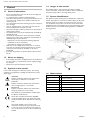
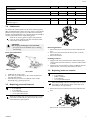
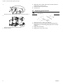
Invacare® Ultra Low Maxx by
Motion Concepts
Supplement to power wheelchair service manual
en
DEALER: Keep this manual.
The procedures in this manual MUST be performed by a qualified
technician.
Modular Power Positioning System
Service Manual
©2015 Invacare® Corporation
All rights reserved. Republication, duplication or modification in whole or in part is prohibited without prior written
permission from Invacare. Trademarks are identified by ™ and ®. All trademarks are owned by or licensed to Invacare
Corporation or its subsidiaries unless otherwise noted.
Contents
1 General . . . . . . . . . . . . . . . . . . . . . . . . . . . . . . . . . . . . . . .
1.1 General information. . . . . . . . . . . . . . . . . . . . . . . . . . . . .
1.2 Notes on shipping . . . . . . . . . . . . . . . . . . . . . . . . . . . . . .
1.3 Symbols in this manual . . . . . . . . . . . . . . . . . . . . . . . . . . .
1.4 Images in this manual . . . . . . . . . . . . . . . . . . . . . . . . . . . .
1.5 System Identification . . . . . . . . . . . . . . . . . . . . . . . . . . . .
1.6 Abbreviations . . . . . . . . . . . . . . . . . . . . . . . . . . . . . . . . .
4
4
4
4
4
4
4
2 Safety . . . . . . . . . . . . . . . . . . . . . . . . . . . . . . . . . . . . . . . . . 5
2.1 Safety and fitting instructions . . . . . . . . . . . . . . . . . . . . . . 5
3 Service . . . . . . . . . . . . . . . . . . . . . . . . . . . . . . . . . . . . . . . .
3.1 Tightening torques . . . . . . . . . . . . . . . . . . . . . . . . . . . . . .
3.2 System Review Checklist . . . . . . . . . . . . . . . . . . . . . . . . .
3.3 Inspection checklist . . . . . . . . . . . . . . . . . . . . . . . . . . . . .
3.4 Lubrication . . . . . . . . . . . . . . . . . . . . . . . . . . . . . . . . . . .
3.5 Replacing powered backrest . . . . . . . . . . . . . . . . . . . . . . .
3.6 Replacing backrest actuator . . . . . . . . . . . . . . . . . . . . . . .
3.7 Replacing postural belt . . . . . . . . . . . . . . . . . . . . . . . . . . .
6
6
6
6
7
7
7
8
4 Settings and Adjustments . . . . . . . . . . . . . . . . . . . . . . . .
4.1 Removing/Installing seat . . . . . . . . . . . . . . . . . . . . . . . . . .
4.2 Removing/Installing tilt module / lifter/tilt module. . . . . . . .
4.3 Seat depth adjustment . . . . . . . . . . . . . . . . . . . . . . . . . . .
4.4 Adjusting seat width and backrest width . . . . . . . . . . . . . .
4.5 Adjusting seat height . . . . . . . . . . . . . . . . . . . . . . . . . . . .
4.6 Setting pre-tilt . . . . . . . . . . . . . . . . . . . . . . . . . . . . . . . . .
4.7 Adjusting backrest height . . . . . . . . . . . . . . . . . . . . . . . . .
4.8 Adjusting backrest precline angle . . . . . . . . . . . . . . . . . . .
4.9 Adjusting cantilever flip-back armrest . . . . . . . . . . . . . . . .
4.10 Adjusting recline armrest . . . . . . . . . . . . . . . . . . . . . . . .
4.11 Adjusting QuadLink . . . . . . . . . . . . . . . . . . . . . . . . . . . .
4.11.1 Installing remote onto Quad Link . . . . . . . . . . . . . . . .
4.11.2 Reversing the mounting position . . . . . . . . . . . . . . . .
4.11.3 Securing the remote cable . . . . . . . . . . . . . . . . . . . . .
4.12 Adjusting footplate width . . . . . . . . . . . . . . . . . . . . . . . .
4.13 Setting drive lockout and limit switches . . . . . . . . . . . . . .
4.14 Center of Gravity (CG) Adjustments (forward and
aft) . . . . . . . . . . . . . . . . . . . . . . . . . . . . . . . . . . . . . . . .
9
9
9
9
10
10
11
11
12
12
13
13
13
13
14
15
15
15
Invacare® Ultra Low Maxx by Motion Concepts
1 General
1.1 General information
•
•
•
•
•
•
•
•
•
•
Service and maintenance work must be carried out taking this
service manual into account.
It is imperative that you observe safety information.
Information about operation or about general maintenance and
care work on the mobility device should be taken from the
operating manual.
You can find information about ordering spare parts in the spare
parts catalogue.
Only use original Invacare® spare parts. The warranty will
become invalid if other spare parts are used!
We reserve the right to make any alterations on the grounds of
technical improvements.
The mobility device may only be maintained and overhauled by
qualified personnel.
The minimum requirement for service technicians is suitable
training, such as in the cycle or orthopedic mechanics fields, or
sufficiently long-term job experience.
1.4 Images in this manual
The detailed images in this manual are given digits to identify
various components. Component numbers in text and operational
instructions always relate to the image directly above.
1.5 System Identification
Each Motion Concepts seating system is identified by a unique serial
number, which allows us to trace the production history of the system
and better equips us to address any service issues that may occur
over the lifetime of the product. The location of the serial number
identification plate varies depending on the type of positioning system
installed. There are two possible mounting locations as indicated in
the images below.
– Experience in the use of electrical measuring equipment
(multimeters) is also a requirement.
– Special Invacare training is recommended.
Alterations to the mobility device which occur as a result of
incorrectly or improperly executed maintenance or overhaul
work lead to the exclusion of all liability on the side of
INVACARE.
If you have any problems or questions please contact Invacare
Service.
1.2 Notes on shipping
•
•
If the mobility device has to be shipped back to the manufacturer
for major repairs, you should always use the original packaging
for transport.
Please attach a precise description of the fault.
1.3 Symbols in this manual
In this manual warnings are indicated by symbols. The warning
symbols are accompanied by a heading that indicates the severity
of the danger.
WARNING
Indicates a hazardous situation that could result in
serious injury or death if it is not avoided.
CAUTION
Indicates a hazardous situation that could result in
minor or slight injury if it is not avoided.
IMPORTANT
Indicates a hazardous situation that could result in
damage to property if it is not avoided.
1.6 Abbreviations
Abbreviation
Meaning
CG
=
Center of Gravity
DLO
=
Drive Lockout
ESR
=
Enhanced Shear Reduction
PES
=
Power Elevating Seat
PPS
=
Power Positioning System
STF
=
Seat-To-Floor Height
Gives useful tips, recommendations and information
for efficient, trouble-free use.
This product complies with Directive 93/42/EEC
concerning medical devices. The launch date of this
product is stated in the CE declaration of conformity.
Tools:
This symbol identifies a list of various tools,
components and items which you will need in order
to carry out certain work. Please do not attempt to
carry out the work if you do not have the listed tools
available.
4
1586649-A
Safety
2 Safety
2.1 Safety and fitting instructions
These safety instructions are intended to prevent accidents at work,
and it is imperative that they are observed.
Before any inspection or repair work
•
•
Read and observe this repair manual and the associated user
manual.
Observe the minimum requirements for carrying out the work
(see 1.1 General information, page 4 ).
Personal safety equipment
Safety shoes
The mobility device, and some of its components, are very heavy.
These parts can result in injuries to the feet if they are allowed to
drop.
•
Wear standardized safety shoes during all work.
Eye protection
It is possible that battery acid can be discharged when working on
defective batteries or when handling batteries improperly.
•
Always wear eye protection when working on any defective or
possibly defective batteries.
CAUTION!
Risk of burns from hot surfaces on the motor
– Allow the motors to cool down before commencing
work on them.
CAUTION!
Injury hazard and risk of damage to vehicle due
to improper or incomplete maintenance work
– Use only undamaged tools in good condition.
– Some moving parts are mounted in sockets with PTFE
coating (Teflon™). Never grease these sockets!
– Never use "normal" nuts instead of self-locking nuts.
– Always use correctly-dimensioned washers and
spacers.
– When reassembling, always replace any cable ties
which were cut during dismantling.
– After completing your work / before renewed start-up
of the mobility device, check all connections for tight
fitting.
– After completing your work / before renewed start-up
of the mobility device, check all parts for correct
locking.
– Only operate the vehicle with the approved tire
pressures (see technical data).
– Check all electrical components for correct function.
Note that incorrect polarity can result in damage to
the electronics.
– Always carry out a trial run at the end of your work.
Safety gloves
It is possible that battery acid can be discharged when working on
defective batteries or when handling batteries improperly.
•
Always wear acid-proof safety gloves when working on any
defective or possibly defective batteries.
General safety information and information about
fitting / removal
CAUTION!
Risk of crushing
Various components such as the drive unit, batteries,
seat etc are very heavy. This results in injury hazards to
your hands.
– Note the high weight of some components. This
applies especially to the removal of drive units,
batteries and the seat.
CAUTION!
Injury hazard if the vehicle starts moving
unintentionally during repair work
– Switch the power supply off (ON/OFF key).
– Engage the drive.
– Before jacking up, secure the vehicle by using chocks
to block the wheels.
CAUTION!
Fire and burn hazard due to electrical short-circuit
– The mobility device must be completely switched off
before removal of voltage-carrying components! To
do this, remove the batteries.
– Avoid short-circuiting the contacts when carrying out
measurements on voltage-carrying components.
1586649-A
CAUTION!
Risk of injury and damage to property, if the
maximum speed reduction on a wheelchair with
a lifter does not function correctly
The wheelchair’s control unit must reduce the maximum
possible speed as soon as the lifter is raised.
– Test the maximum speed reduction for correct
function after any maintenance work or modifications
to the wheelchair.
CAUTION!
Any changes to the drive program can affect the
driving characteristics and the tipping stability of
the vehicle
– Changes to the drive program may only be carried out
by trained Invacare specialist dealers.
– Invacare supplies all mobility devices with a standard
drive program ex-works. Invacare can only give a
warranty for safe vehicle driving behavior - especially
tipping stability - for this standard drive program.
Mark all current settings for the mobility device (seat,
armrests, backrest etc.), and the associated cable connecting
plugs, before dismantling. This makes reassembly easier. All
plugs are fitted with mechanical safety devices which prevent
release of the connecting plugs during operation. To release
the connecting plugs the safety devices must be pressed in.
When reassembling ensure that these safety devices are
correctly engaged.
5
Invacare® Ultra Low Maxx by Motion Concepts
3.2 System Review Checklist
3 Service
Following any installation, set-up and/or adjustment related
to the seating system always test the system over its full range
of positioning functions to ensure all motors, safety limits are
functioning correctly. Verify that all mounting hardware and
critical components are also installed/adjusted properly.
3.1 Tightening torques
CAUTION!
Damage can be caused to the mobility device due
to improperly tightened screws, nuts or plastic
connections.
– Always tighten screws, nuts etc to the stated tightening
torque.
– Only tighten screws or nuts which are not listed here
fingertight.
The tightening torques stated in the following list are based on the
thread diameter for the nuts and bolts for which no specific values
have been determined. All values assume dry and de-greased threads.
Thread
Tightening torque in
Nm ±10%
M4
3 Nm
M5
6 Nm
M6
10 Nm
M8
25 Nm
M10
49 Nm
M12
80 Nm
M14
120 Nm
M16
180 Nm
The following checklist is provided as a reference when conducting
a final review/inspection of the wheelchair.
•
•
•
•
•
•
•
•
•
•
•
•
•
•
•
•
Check all fasteners/mounting hardware to ensure that they have
been properly tightened.
Check the drive lockout limit is functioning.
Check the reduced speed drive (if applicable)
Check the tilt (tilt/recline) limit (if applicable).
Check the full range of tilt and recline and elevate (as applicable).
Make certain that there is no interference. Make sure that the
wheelchair is stable with the client in it over the entire range.
Check power legrest function (if applicable). Ensure there is
appropriate ground clearance in the retracted position, and
check for interference over the full range of travel.
Check all wires and cables over the complete tilt/recline/elevate
range for pulling, crushing or tight bends.
Check that the charger functions properly.
Check that the acceleration and deceleration of the wheelchair
have been programmed to levels appropriate for the user.
Check all of the wheelchair drive functions.
Check that the rod-ends on the tilt and recline actuators have
been properly pinned (if applicable).
Check the anti-tipper latching system (if applicable).
Check that the anti-tipper extensions are installed (if required).
If the front or rear anti-tippers are adjustable, check that they
have been set to the appropriate position for the user.
Test drive the wheelchair and operate the seating system.
Ensure the user manual is provided to the end user.
3.3 Inspection checklist
Item
Initially
Monthly
6 Months
Periodically
Batteries
Load test batteries (individually)
X
X
Ensure batteries are clean (free from corrosion/ moisture/ dirt)
X
X
Ensure connections are tight and clean
X
X
Electrical / Wiring Harnesses
Check for pinches or pulls in wiring (over full range of seating system)
X
X
Inspect for wear & tear damage to wires
X
X
Ensure connections are secure
X
X
Actuators (where applicable)
Ensure actuator rod ends are properly pinned
X
X
Ensure no interference/sticking during system operation (over full range of
seating system)
X
X
Inspect for excessive noise or grinding
X
X
Hardware and Components
6
Inspect mounting hardware (seating system to base)
X
X
Inspect all adjustment hardware to ensure nuts and screws are secure (i.e.
side rails, recline module, legrests/foot plates/receivers
X
X
Inspect for loose parts/rattling sounds - ensure all nuts and screws are secure
X
X
Inspect that all pivot points are operating smoothly & freely and secured
(do not overtighten)
X
X
1586649-A
Service
Item
Initially
Monthly
Check limit switch settings
X
X
Ensure DLO functions correctly
X
X
6 Months
Periodically
Limit Switches
Pivots, Glide Blocks & Track Maintenance
X
Ensure slide channel is free from dirt/dust/grime
X
X
Lightly lubricate main pivot points, using a general purpose oil (see 3.4
Lubrication, page 7 )
3.4 Lubrication
To maintain the smooth operation of the power positioning system
(PPS), periodical lubrication of the main pivot points is recommended.
Motion Concepts seating systems are pre-lubricated at the factory,
however occasional lubrication using a general purpose oil will help to
maintain optimal performance of your seating system.
Avoid the use of heavy grease or high viscosity lubricants
as this can cause a build-up of dirt and contaminates which
could reduce overall performance.
CAUTION!
Risk of injury and damage to the wheelchair
– Turn power off to the wheelchair prior to cleaning
and lubricating.
Pivot point lubrication
Removing backrest
1.
2.
3.
Remove the seat pan and disconnect the power cable from the
base.
Remove screws from the backrest tube brackets A and the
actuator bracket B.
Remove the backrest.
Installing backrest
1.
2.
Lifter module
Tilt module
1.
2.
3.
3.6 Replacing backrest actuator
Tools:
• 3 mm Allen key
• Phillips screwdriver
• 6 mm Allen key
• 13 mm open-ended spanner
Tilt/Elevate the seating system.
Use a clean rag to wipe away any dirt, residue around pivots
and along slide channels.
Lubricate main pivot points (as indicated) on the module
periodically using a general purpose oil.
When disassembling, take care of small parts such as screws
and washers. Put all small parts down so that they can be
reassembled in the right sequence.
3.5 Replacing powered backrest
Tools:
• 5 mm Allen key
• 6 mm Allen key
• 10 mm open-ended spanner
• 13 mm open-ended spanner
Align the holes of the powered backrest tubes with the upper
mounting holes in the tube brackets A and secure with hardware
as shown.
Align the lower ends of backrest actuator and ESR link with the
actuator bracket B and secure with hardware as shown.
1.
Remove the seat pan and disconnect the power cable from the
base.
2.
When disassembling, take care of small parts such as screws
and washers. Put all small parts down so that they can be
reassembled in the right sequence.
Remove screw A and backrest cover B.
1586649-A
7
Invacare® Ultra Low Maxx by Motion Concepts
3.
6.
7.
8.
Align ends of new actuator with actuator brackets and secure
with hardware as shown above.
Connect actuator to power module.
Install seat pan.
3.7 Replacing postural belt
Tools:
• 5 mm Allen key
Remove screws A, unhook clamp strap B, and remove clamp C.
4.
1.
2.
5.
8
Remove screws from the actuator brackets.
Remove actuator.
3.
4.
Loosen the screw (1) with a 5 mm Allen key.
Remove the screw (1), the washer (2), the postural belt, the
sliding bushing (3) and the sliding block (4) from the seat frame
profile (5).
Replace the postural belt.
Refit the parts in the reverse order.
1586649-A
Settings and Adjustments
4 Settings and Adjustments
4.1 Removing/Installing seat
CAUTION!
Risk of strains from lifting heavy parts!
– Use proper lifting techniques.
Depending on whether you have a tilt module or lifter/tilt-module
installed or not, there are two ways to remove and install the seat:
•
•
With the seat installed directly on the seat frame.
With the seat installed on a module or tilt wedge.
Removing seat from seat frame
Installing seat takes place in reverse order.
4.2 Removing/Installing tilt module /
lifter/tilt module
Tools:
• 10 mm open-ended spanner
Removing module
1.
2.
Remove seat. Refer to 4.1 Removing/Installing seat, page 9 .
If a tilt wedge is installed, remove it. Refer to 4.6 Setting pre-tilt,
page 11.
3.
Tools:
• 2 x 13 mm open–ended spanner
4.
5.
6.
Remove screws and washers A.
Remove module.
If a rear wiring bumper is installed, remove its screws and
washers B.
Remove bumper from module.
Installing module
1.
2.
Remove screws and washers A on both sides.
Remove seat.
Installing seat takes place in reverse order. We recommend
to use new Nyloc nuts to ensure safe locking.
Removing seat from module or tilt wedge
Tools:
• 6 mm Allen key
1.
2.
3.
4.
5.
6.
Align module to correct depth.
Insert screws and washers and tighten.
If needed, align rear wiring bumper.
Insert screws and washers and tighten.
If needed, align tilt wedge with holes on module and in the
desired orientation and install.
Align seat with holes on tilt wedge or module and install.
4.3 Seat depth adjustment
The seat depth has a major influence on the selection of
the center of gravity of the seat. This impacts its dynamic
stability. If you make a major change to the seat depth, the
center of gravity of the seat must also be adjusted. Refer
to 4.14 Center of Gravity (CG) Adjustments (forward and
aft), page 15.
Seat depth adjustments will often require further adjustments
to the legrest(s) and/or legrest receivers to compensate for
the change in seat depth.
Seat depths of 530 mm and larger will require a seat depth
extension kit.
Tools:
• 13 mm wrench
Example of tilt module
1.
2.
Example of anterior tilt
wedge
Remove screws and washers A on both sides.
Remove seat.
1586649-A
9
Invacare® Ultra Low Maxx by Motion Concepts
1.
2.
3.
4.
Tilt or lift seat for easier access.
Loosen screws of side rails A — two on each side.
Adjust side rails to desired depth.
Tighten screws.
4.4 Adjusting seat width and backrest width
Seat width adjustments are more complex than depth
adjustments and require additional adjustments/changes to
the seat frame and backrest assembly.
Remove screws A. Adjust brackets B to desired width.
6.
The Ultra Low Maxx seat frames are available in two width ranges to
accommodate a wide range of seat sizes from 405 mm up to 610 mm.
The Ultra Low seat side frames are used to adjust the width of the
seating system. Side frames are adjustable at 12.5 mm intervals per
side (left/right), which allow for 25 mm incremental width adjustments
up to a maximum range of 75 mm.
Tools:
• 3 mm Allen key
• 5 mm Allen key
• 6 mm Allen key
• 10 mm wrench
If necessary, remove screw A and replace cross plate.
The cross plate is available in two widths:
• 405–505 mm
• 505–610 mm
1.
7.
8.
9.
Reassemble brackets.
Install backrest pan in new width.
Adjust side frames to desired width.
Make sure that both sides are set to the same width.
10. Insert screws and tighten.
11. Reinstall front seat pans and adjust to new seat width.
12. Insert screws and tighten.
2.
3.
Loosen and remove screws of front seat pans A.
Remove front seat pans.
4.5 Adjusting seat height
Tools:
• 13 mm open-ended spanner
Seat height 420 mm
(only in combination
with 8.5° anterior
tilt)
On each side, loosen and remove screws of side frame parts
fore A and aft B.
4.
Low interface
bracket
Seat height 440 mm
Seat height 460 mm
Remove screws A. Remove backrest pan.
5.
High interface
bracket
10
Seat height 480 mm
1586649-A
Settings and Adjustments
1.
2.
3.
4.
5.
6.
Remove seat. Refer to 4.1 Removing/Installing seat, page 9 .
Remove tilt module or lifter/tilt module. Refer to 4.2
Removing/Installing tilt module / lifter/tilt module, page 9 .
Loosen and remove screws A.
Adjust bracket to desired height. See graphics above.
Switch to other bracket size if needed.
Insert and tighten screws.
Install tilt module or lifter/tilt module and seat.
1.
4.6 Setting pre-tilt
The seating system can be set to a predefined anterior or posterior
tilt:
•
•
•
5° anterior tilt which reduces the maximum possible tilt by 5°
10° anterior tilt which reduces the maximum possible tilt by 10°
5° posterior tilt which increases the maximum possible tilt by 5°
Remove screws and washers A.
Orientation of tilt wedge
5° anterior tilt
10° anterior tilt
2.
5° posterior tilt
Setting the tilt
CAUTION!
Risk of strains from lifting heavy parts!
– Use proper lifting techniques.
Align bottom hole of backrest pan to hole of desired height on
backrest tube:
Tools:
• 6 mm Allen key
1.
2.
3.
4.
Remove seat. Refer to 4.1 Removing/Installing seat, page 9 .
Align tilt wedge with holes on module and in the desired
orientation. See graphics above.
Insert screws and tighten.
Align seat with holes on tilt wedge and install.
4.7 Adjusting backrest height
The backrest pans are available in different heights. In addition, the
overall height can be adjusted by adjusting the gap between backrest
pan and seat.
High Back
•
•
•
3.
A = 200 mm gap
B = 175 mm gap
C = 150 mm gap
Insert screws and washers and tighten.
Matrx
The Matrx Elite TR Back shown in this section serves as an
example. Matrx Elite Deep Back and Matrx Posture Back
are adjusted the same way.
Tools:
• 5 mm Allen key
• 6 mm Allen key
• 10 mm wrench
Tools:
• 10 mm wrench
1586649-A
11
Invacare® Ultra Low Maxx by Motion Concepts
1.
1.
2.
Remove screws A. Remove backrest pan.
2.
3.
Remove top screws and washersA.
Adjust thick 6.35 mm (0.25”) washer inside backrest tube to top
hole. Align with top hole of pushbar. See detail in graphic.
Insert screws and washers and tighten.
Adjusting backrest angle to 30° precline
Tools:
• 5 mm Allen key
• 6 mm Allen key
• 10 mm wrench
• 13 mm wrench
Remove nuts and washers A and adjust hanger plate B to
desired gap height. If necessary, also adjust side plate C.
See graphics below for details on how to combine hanger plate
and side plate for which gap height.
Gap
Height
Screw Position Side
Plate
Screw Position
Hanger Plate
150 mm
1.
2.
3.
4.
Remove screws and washersA.
Adjust thick 6.35 mm (0.25”) washer inside backrest tube to
bottom hole. Align with bottom hole of pushbar. See detail in
graphic.
Insert screws and washers and tighten.
175 mm
200 mm
5.
6.
Remove screws, washers and nuts A.
Replace ESR crankarm B with precline ESR crankarm.
Insert screws, washers and nuts and tighten.
4.9 Adjusting cantilever flip-back armrest
Adjust armrest width
Tools:
• 6 mm Allen key
4.8 Adjusting backrest precline angle
Adjusting backrest angle to 8° precline
Tools:
• 13 mm wrench
12
1586649-A
Settings and Adjustments
1.
2.
3.
Remove screw A.
Adjust armrest B to desired width.
Insert and tighten screw.
Adjust armrest height
Tools:
• 13 mm open-ended spanner
3.
4.
To adjust the armrest receiver assembly to match the height
adjustment of the pivot arm assembly, loosen the two screws
B on the inside of the armrest receiver and slide the armrest
receiver up/down the recline tube to the desired height.
Retighten screws.
4.11 Adjusting QuadLink
4.11.1 Installing remote onto Quad Link
By default, the remote is mounted centered regardless of which side
of the wheelchair the remote is mounted on. The position of the
remote A on the adjustable remote tray B can nevertheless be
adapted as shown below:
1.
2.
3.
Loosen screws A.
Adjust armrest B to desired height.
Tighten screws.
Adjust armrest angle
Tools:
• 13 mm open-ended spanner
1.
2.
Right Mount Front View (For
Right Hand Use)
Left Mount Front View (For Left
Hand Use)
Loosen lock nut A.
Adjust armrest angle by adjusting thread rod with thumb nut B:
•
•
3.
To lift armrest, screw in thread rod.
To lower armrest, screw out thread rod.
Tighten lock nut.
4.10 Adjusting recline armrest
The standard recline armrest has an adjustable pivot arm to allow
height adjustments in 13 mm increments.
Tools:
• 5 mm Allen key
• 13 mm open-ended spanner
1.
If necessary, remove the adjustable remote tray from the Quad
Link by performing the following steps:
a.
b.
2.
3.
4.
5.
Loosen the two cap screws F securing the adjustable
remote tray B to the Quad Link E.
Remove the adjustable remote tray from the Quad Link.
Secure the remote to the adjustable remote tray using the four
screws C and four spacers G. Torque the screws to 3.6 Nm.
Insert the adjustable remote tray into large hole D in the Quad
Link.
Adjust the adjustable remote tray to the desired position. Refer
to Adjusting the remote position in the user manual.
Secure the remote cable. Refer to 4.11.3 Securing the remote
cable, page 14.
4.11.2 Reversing the mounting position
Perform this procedure to reverse the Quad Link from the right side
to the left or vice‐versa.
1.
2.
Remove screw A and slide the inner pivot arm up/down to the
desired height.
Reinstall screw.
1586649-A
Take note of position and orientation of mounting hardware
for reinstalling the remote assembly (remote mount, Quad
Link and remote).
13
Invacare® Ultra Low Maxx by Motion Concepts
Repositioning the remote mount
3.
This procedure applies to both fixed and adjustable height remote
mounts.
Left Mount
Right Mount
Rearrange the linkage bars to the desired position shown above.
The linkage bars will align to a different set of mounting
holes than the ones previously used.
Ensure the tab is aligned with a tab mounting hole (see
upper graphic).
4.
1.
2.
3.
4.
5.
6.
7.
Turn the adjustment lock lever D to remove the remote
mounting tube C from the remote mount E.
Loosen the three upper set screws A securing the remote
mount to the arm tube B.
Remove the remote mount.
Install the remote mount onto the opposite arm tube.
Tighten the three upper set screws to secure the remote mount
to the arm tube.
Install the remote mounting tube into the remote mount.
Turn the adjustment lock lever to secure the remote mounting
tube at the desired position.
5.
Secure the linkage bars to the front and rear portions of the
Quad Link using the four shoulder screws.
Secure the four shoulder screws to the Quad Link using the four
set screws.
Each corner mounting hole in the front or rear portion
of the Quad Link has a corresponding set screw
mounting hole. The set screw mounting hole will be
along the edge of the Quad Link near the corners.
Repositioning the remote
Repositioning the Quad Link
1.
2.
3.
1.
Remove the four set screws E securing the four shoulder screws
A to the Quad Link.
Each corner mounting hole in the front F or rear C
portion of the Quad Link has a corresponding set screw
mounting hole. The set screw mounting hole will be
along the edge of the Quad Link near the corners.
2.
Remove the four shoulder screws securing the linkage bars G to
the front and rear portions of the Quad Link.
4.
Loosen the two cap screws F securing the adjustable remote
tray B to the Quad Link E.
Remove the remote A with the adjustable remote tray attached.
Remove the two screws C securing remote to the adjustable
remote tray.
Install the remote on the opposite side of the adjustable remote
tray. Refer to 4.11.1 Installing remote onto Quad Link, page 13.
4.11.3 Securing the remote cable
To ensure proper use and operation of the quad link, the remote
cable must be properly secured.
The linkage bars will disconnect from each other and
the Quad Link.
1.
2.
3.
14
If present, secure the remote cable D to the cable bracket A.
Position the remote cable along the remote mounting tube b.
Using a tie‐wrap C, secure the remote cable to the rear of the
remote mounting tube so that the remote cable is positioned
along the inside of the tube, facing the inside of the wheelchair.
1586649-A
Settings and Adjustments
4.12 Adjusting footplate width
The footplate width is adjusted via spacers:
•
•
Add spacers to increase width.
Remove spacers to decrease width.
Tools:
• 6 mm Allen key
switch value has been set, ensure that the elevating actuator lockout
is tested. Further adjustments may be required.
Speed reduction microswitch for power elevating seats
All modular systems with power elevating seats (PES) are fitted with
a microswitch for the speed reduction. This microswitch reduces
the speed by 30% when the seat actuator is elevated beyond a
recommended 100 mm (4") limit, measured from the home (lowest)
position. The microswitch/speed reduction functions as a ‘normally
closed’ circuit. This provides fail safe operation. As soon as the seat
is elevated over the 100 mm (4") limit, the switch is opened and the
speed reduction is engaged. The microswitch is typically mounted to
the underside of the seating system and is attached to an actuator
mounting plate in either a vertical or horizontal position (depending
on the seating system). Ensure the speed reduction microswitch is
tested after installation. Further adjustments may be required.
Setting the max. back angle limit switch
1.
2.
3.
Remove screw A.
Remove or add spacers B.
Retighten screw.
4.13 Setting drive lockout and limit switches
Setting the drive lockout for tilt/recline systems
All modular systems with tilt and/or recline functions are supplied
with a drive lockout (DLO) switch. This prevents the drive motors
from operating if the backrest is positioned beyond a pre-determined
angle. The maximum drive lockout angle is 60° from the vertical
(see diagram below). After the angle has been set, ensure the drive
lockout is tested. Further adjustments may be required.
All modular systems with tilt and recline functions are available with
a max. back angle limit function. This function prevents the back
angle from extending beyond a pre-set angle. The correct max. back
angle limit differs for each installation. The limit switch should be set
so that with any combination of tilt and recline, there is no chance
of interference between the backrest of the modular system and the
wheelchair base or any accessories located at the back. The recline
angle should never extend beyond 5° from the horizontal (see graphic
below). After the back angle has been set, ensure the max. back angle
limit is tested. Further adjustments may be required.
For a tilt/recline seating system, the switch is typically mounted to
the side of the actuator module mounting bracket on the back of
the system.
For a tilt/recline seating system the DLO switch is typically mounted
to the side of the actuator module on the backrest pan.
If the drive is locked out when the switch angle is adjusted,
the tilt or recline will have to be activated again before
re-testing the drive lockout. The drive lockout will remain
engaged until the tilt or recline has been activated, regardless
of the switch angle.
The drive lockout limit should always be set to the angle
that best meets the individual needs of the user and overall
stability of the wheelchair. However, the DLO angle should
not exceed the maximum 60° backrest angle.
– Ensure base is on a level surface when adjusting limits.
Setting the power elevating seat (PES) lockout limit
switch for tilt-elevating systems
All modular systems with tilt and recline functions in combination
with a power elevating seat (PES) are fitted with a PES lockout limit
switch. This limit switch prevents the PES actuator from elevating
when the DLO is activated. The limit switch used to set the elevating
actuator lockout is identified by a WHITE colored end. After the
1586649-A
The max. back limit switch will need to be set to best meet
the needs of the user. However, the recline angle should not
be permitted to extend beyond the recommended 5°.
– Ensure base is on a level surface when adjusting limits.
4.14 Center of Gravity (CG) Adjustments
(forward and aft)
The Ultra Low Maxx power positioning system may be adjusted in
the forward and aft direction when being mounted onto a power
base. Several factors must be considered when determining the
correct position for the user, including the clients weight distribution
and body type. It is very important to ensure adequate stability is
maintained during driving, and in the various power seating positions.
When determining a suitable system for a client, it is equally important
to ensure that the user’s weight does not exceed (the lesser of)
the calculated wheelchair weight capacity or the designated power
positioning system (PPS) weight capacity. A weight capacity calculator
has been provided for reference, to calculate the total user weight
and the wheelchair weight capacity (see below).
Important information (for dealers and users)
The Ultra Low Maxx power positioning system is designed to
accommodate a wide range of user needs. Only the dealer and the
healthcare professional can ensure that the system meets the user’s
individual requirements. It is the dealer’s responsibility to ensure that
the wheelchair and the power positioning system are set up properly
and safely for the end user’s specific needs.
15
Invacare® Ultra Low Maxx by Motion Concepts
Stability
480 mm – 580 mm deep seat frame
By changing the seating position (tilting, reclining, or elevating), the
user is changing the stability characteristics of the wheelchair. It is
very important that the system is set up so that it is stable in all
seating positions. When evaluating stability, remember the following:
•
•
•
•
•
•
•
•
The Ultra Low Maxx system can be mounted onto the power
base in various fore and aft positions. Make certain that the
position selected provides the user with maximum stability over
the full range of seating positions.
Consider all personal gear and accessories (backpacks, vent
systems, extra batteries, etc.) that will be carried on the
wheelchair. For example, a loaded backpack, attached to the
back of the seating system, can significantly reduce the rearward
stability of the wheelchair. Consider the backrest being used.
For example, a recessed backrest can shift the user’s center of
gravity back and significantly reduce the rearward stability of the
wheelchair. Conversely, a thick back cushion will shift the user
forward and reduce the wheelchairs forward stability.
If using a backrest other than Invacare, check with manufacturer
to ensure it is suitable for power positioning systems.
Consider the seat cushion being used. A thick seat cushion will
raise the user’s center of gravity and reduce the wheelchairs
stability in all directions.
The Ultra Low Maxx system is equipped with drive lockouts.
Make sure this is set so as not to compromise the user’s stability
while driving.
All power bases have programmable controllers which allow
adjustment of the maximum acceleration and deceleration of the
wheelchair. Make sure that these are set to an appropriate level
for the system and for the user.
Ensure all medical conditions are considered when setting up the
wheelchair. Involuntary muscle movement such as spasming may
affect the stability of the wheelchair, especially when the seating
system is in a tilted or reclined position.
When a system is fully tilted or reclined, the front wheels of the
power base should never come off the ground. If this occurs,
you must adapt the system’s center of gravity.
Typical 480 mm setting
Typical 580 mm setting
Adjusting the center of gravity
To achieve the best overall base stability, the system depth should be
adjusted as far back as possible when the seat depth is deepened. This
will be determined by the type of legrests used.
Tools:
• 2 x 13 mm open-ended spanner
CAUTION!
Risk of strains from lifting heavy parts!
– Use proper lifting techniques.
1.
Typical system depth settings
380 mm – 480 mm deep seat frame
2.
3.
Typical 380 mm setting
16
Loosen screws and nuts and remove together with washers A.
Adjust system to desired position.
Insert screws, nuts and washers and tighten.
Typical 480 mm setting
1586649-A
Notes
Notes
Notes
Invacare Sales Companies
Australia:
Invacare Australia PTY. Ltd.
1 Lenton Place, North Rocks NSW
2151
Australia
Phone: 1800 460 460
Fax: 1800 814 367
[email protected]
www.invacare.com.au
Canada:
Invacare Canada LP
570 Matheson Blvd E. Unit 8
Mississauga Ontario
L4Z 4G4, Canada
Phone: (905) 890 8300
Fax: (905) 501 4336
United Kingdom:
Invacare Limited
Pencoed Technology Park, Pencoed
Bridgend CF35 5AQ
Tel: (44) (0) 1656 776 222
Fax: (44) (0) 1656 776 220
[email protected]
www.invacare.co.uk
Eastern Europe & Middle East:
Invacare GmbH, EDO
Kleiststraße 49
D-32457 Porta Westfalica
Tel: (49) (0)57 31 754 540
Fax: (49) (0)57 31 754 541
[email protected]
www.invacare.eu.com
Ireland:
Invacare Ireland Ltd,
Unit 5 Seatown Business Campus
Seatown Road, Swords, County Dublin
Tel : (353) 1 810 7084
Fax: (353) 1 810 7085
[email protected]
www.invacare.ie
New Zealand:
Invacare New Zealand Ltd
4 Westfield Place, Mt Wellington 1060
New Zealand
Phone: 0800 468 222
Fax: 0800 807 788
[email protected]
www.invacare.co.nz
Manufacturer:
Invacare Deutschland GmbH
Kleiststraße 49
32457 Porta Westfalica
1586649-A
2015-06-12
*1586649A*
Making Life’s Experiences Possible™