1
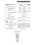
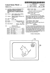
l|||l||||||||IlllllllllllllllllllllllllllllllllIIIIIlllllllllllllllllllllll
US005440351A
United States Patent [191
[11] Patent Number:
Ichino
[45]
[54]
[76]
Date of Patent:
TELEVISION WITH USER-SELECTABLE
4,272,788
RADIO SOUND
4,527,204
7/1985 Kozaki et a1.
4,627,101
2/1985
’
Inventor:
_
5,440,351
Aug. 8, 1995
6/1981 Ogita ..................................... .. 381/3
. 358/194.1
Anderson et al.
455/ 179.1
Ted Icluno, 7351 Artesla Blvd. #6,
4,688,252 8/1987 Kufta et a1. ............... .. 381/4
Buena Park, Calif. 90621
4,779,129 10/1988 Usee et a1.
5,046,107 9/1991 Iwamatsu
358/189
381/107
[211
APP1-N°-= 63,620
5,097,249
[22]
Filed:
5,142,370 8/1992 Wignot et a1. .................... .. 358/189
May 25’ 1993
R l ted U S A r ti
ea
[63]
. .
pp lea
D ta
on
3/1992 Yamamoto ..... ..
FOREIGN PATENT DOCUMENTS
a
2831014 4/1980
Continuation-impart of Ser. No. 817,137, Jan. 6, 1992,
0017017 2/1978
abandoned.
0045712 31/1982
[51]
[52]
Int. 01.6
US.
Cl. ..................................
.............................................
.. 348/729;
.. H04N
348/738;
5/60
[58]
455/ 179.1
Fleld of Search ................... .. 358/198, 184, 194.1,
358/165; 455/151.1, 174.1, 178.1, 179.1, 185.1,
OTHER PUBLICATIONS
Middleton’ Robert G‘, “Television Service Manual,”
5th Edition T Audel Indiana Olis SC
180.2, 187.1, 79; H04N 5/46, 5/60; 381/3, 4,
107, 102, 104, 101; 312/7.2; 348/729, 738, 706
References Cited
[56]
. 358/194.1
U.S. PATENT DOCUMENTS
’
‘
’
P
’
1984
P‘
49
'
Primary Examiner-James J. Groody
Asszstant Examzner-Jeffrey S. Murrell
[57]
ABSTRACT
266,502 10/1982 Heijnen ............................ .. 1314/131
279,095 6/1985 Kato et aL
‘‘‘‘ __ D14/131
A televisim‘ S?‘ with an integrated radi" tuner’ such that
simulcast radio broadcasts may be played through the
290,007
telev1s1on sound system at the viewer’s discretion. A
5/1987
Mano er a1. , _ _ _ _ ,
_ , , , ,_ D14/131
292,097 9/1987 Akita et a1.
gfalgoto -,
1n
298,534 11/1988
0
.. ...
.... .. D14/ 131
user-programmable memory provides the viewer with
---- -
the ability to store multiple television channel/radio
. . . . ..
Turner . . . . . . . . .
-
. . . . .. 1314/131
-
.
-
fr.eq“en°y ‘ilsswatlfms' A ‘6.111016. control def'we .Pro
300,633 4/1989 .Makino et a1. ........... .. 1314/131
“des the my“ “91.96 “P291119 °f Selectmg 61th“
305,024 12/1989 Nishiyori et 3L
normal television audio or radio s1mulcast sound.
2,617,878 11/1952
2,626,315
“ D14/131
Goldfus .......... ..
358/189
1/1953 Farr ........ ..
358/189
4 Claims, 7 Drawing Sheets
5
UHF
/
ANTENNA
l0
,-/2
F20
UHF SIGNALS
UHF MIXER/
VIDEO
(ALL UHF CHANNELS)
OSCILLATOR
PROCESSING
2*’
SINGLE UHF
“1421M
CHANNEL
l4
VHF SIGNALS
(ALL VHF CHANNELS)
VHF RF
AMPUFIER
SINGLE
TV CHANNEL
TV VIDEO
VHF MIXER/
OSCILLATOR TV AUDIO
25
r ---------------------------------------------- — - C- - — -:
|
23
I RADIO
‘ TV AUDIO
IANTENNA
PROCESSING
/
1
Z5 :
I
I
28
.32“
I
I
'
|
L.
4
P‘
f3,
RADIO SIGNALS
Ag)?
TUNER
1
24
$111015 RADIO
STATION
IIMPK
I
I
-
__________________________ _I"_/R_A2'2 MP1? IE°EEEEILL
'
1
1
US. Patent
Aug. 8, 1995
Sheet 7 0f 7
5,440,351
FIG. 7
X
FREQ.
38
FIGS
1047 2058 3069
FREQ. ENTER TV/RADIO
m9@w
@Wv
aha p @M
46'
1
5,440,351
TELEVISION WITH USER-SELECI‘ABLE RADIO
SOUND
This is a Continuation-In-Part of Ser. No. 07/817,137,
?led Jan. 6, 1992, now abandoned.
BACKGROUND-DESCRIPTION OF PRIOR
ART
Heretofore, only FM radio simulcasts could be substi
2
synergy between a video cassette recorder and a televi
sion set. Kozokai’s remote control device cannot be
compared with the remote control device of this inven
tion. Kozokai’s remote control device merely simpli?es
the interactions of two already interdependent video
media, rather than establishing new interactions be
tween two dissimilar and non-interdependent media.
Kozokai’s remote control device automates the steps
necessary to display a VCR signal through a television
set; it performs only mandatory actions. In contrast, a
tuted for a normal television audio program; a viewer
switch on a remote control device which causes radio
has not previously had the option of substituting an AM
sound to be substituted for television audio creates an
interaction between two different media; a new rela
radio simulcast for a television audio program. Televi
sion audio engineers have traditionally seen radio simul
casts as merely stereo versions of the original television
audio broadcast, and have either provided no simulcast
capability or the ability to substitute FM radio simul
casts for the television audio program. The similarities
between FM radio circuitry and television audio cir
cuitry, which permit FM radio signals to be ampli?ed
through pre-existing television audio circuits, have rein
tionship between the two media. This switch is not
essential to the operation of a normal television. It is
only useful when a receiver capable of decoding AM
radio transmissions is incorporated into a television set,
at which time it provides the new and unexpected result
of allowing the viewer to choose between the normal
20 television audio program and _a radio simulcast at the
touch of a button. This switch is neither obvious nor
forced this mindset. A number of inventions which
cost-effective if only FM radio simulcasts are consid
ered. Because FM simulcasts differ from the original
normal television audio program exist in the prior art;
television audio program by being in stereo, and most
however, none of these designs will accommodate AM 25 television sets provide marginal stereo separation, there
allow an FM radio simulcast to be substituted for a
radio simulcasts. By ignoring AM radio, these teachings
is no reason to provide such a switch for a television
exclude nearly all radio simulcasts, since the vast major
with FM-only simulcast capability. Even if the average
television set had widely-separated speakers and excel
lent stereo separation, the scarcity of FM radio simul
ity of all radio simulcasts are found on AM radio.
Portable units with both televisions and AM/FM
radios have been produced, but the radio of these com
casts would prevent such a switch from being cost-ef
bination units has always been separate from the televi
fective. The prior art recognizes this and provides cir
sion of the unit; no provision to substitute radio sound
cuits which automatically compare the strength of the
for television audio has been provided. The radio and
FM simulcast signal against the strength of the televi
television of these combination units have been per
sion audio signal, automatically selecting the stronger of
ceived as separate entities which happen to share a 35 the two signals. The viewer is not burdened with a
common housing.
choice between television audio and FM simulcast
It is well known in the prior art that television audio
sound, since the two are essentially identical.
circuits can be used to amplify FM radio signals; indeed,
Iwamatsu, US. Pat. No. 5,046,107 (1991) discloses a
Middleton teaches that television audio circuitry is
device which adjusts volume such that when the user
quite similar to the circuitry of an FM radio. The prior 40 switches among various audio sources, the volume re
art has made heavy use of this similarity. Wignot et al.,
mains constant. He describes a memory which stores
US. Pat. No. 5,142,370 (1992); Uee et al., US. Pat. No.
preset volume levels and associates each preset volume
4,779,129 (1988); Ogita, US. Pat. No. 4,272,788 (1981);
level with a particular device. Like Kozokai, this device
and foreign patents Gorenje, DT 2831-014 (1980); Hita
chi, 53-17017 (1978); Suzuki, 57-45712(A) (1982); and
Saitou, 57-155885(A) (1982) all use television audio
re?nes pre-existing relationships, rather than creating
45 new attributes. In contrast, a memory which can associ
ate a radio frequency with a given television channel
circuitry to amplify the radio signal. Wignot carries this
and make this radio frequency available whenever the
circuit-sharing to its logical extreme, disclosing a way
television is tuned to the channel creates a new attribute
for the television channel. It creates a new relationship
to make a television audio circuit function ef?ciently as
an FM radio receiver.
50 between the television channel and the radio frequency,
Every instance of applicable prior art known to the
applicant has either ignored the potential synergy be
with the new and unexpected result that the viewer has
a choice between the standard television audio program
tween radio sirnulcasts and television sets, or else lim~
and one or more radio simulcasts which describe the
ited itself solely to FM radio simulcasts by routing the
same event, but which differ in content among them
radio signal through television circuitry to be ampli?ed.
selves and the original television audio broadcast.
The need of the non-English-speaking person to
Television audio circuits cannot be shared with an AM
radio; the intermediate frequencies of the two signals
are too dissimilar. Besides excluding AM radio simul
casts, the prior art has the additional disadvantage of
watch a television picture while listening to a simulcast
in his or her native tongue has not heretofore been fully
addressed. Second-language simulcasts are to be found
depending on a particular television broadcast format. 60 on AM, not on FM radio. Television broadcasters have
It is unlikely that Saitou’s device will work in conjunc
tion with an HDTV television set: Saitou, along with
the entire body of applicable prior art, relies on a fortu
attempted to accommodate non-English-speaking per
sons by offering a Secondary Audio Program (SAP),
but not all languages are covered; nor is SAP offered
itous similarity between television audio circuitry and
for every program; nor is SAP available on every
FM radio that has little chance of surviving the transi 65 broadcast channel. Radio simulcasts in a number of
tion from analog to digital television.
languages exist today; the prior art has ignored them by
Kozokai et al., US. Pat. No. 4,527,204 (1985) dis
designing televisions which are either con?ned to re
closes a remote control device which facilitates the
ceiving FM radio broadcasts or which cannot receive
3
5,440,351
4
radio broadcasts at all. The present invention allows
Another object and advantage is to provide a sports
AM foreign-language simulcasts to be easily accessed,
fan with a convenient way of watching a sports event
on television while listening to a radio simulcast of the
without impairing the viewer’s ability to receive a tele
vision SAP audio broadcast.
Many sports fans would prefer to watch sports on
television while listening to the play-by-play commen
tary from their local radio announcer, but desire the
option to hear the normal television audio program
same event.
Another object and advantage is to provide a method
of quickly and easily switching back and forth between
the television audio program and the radio simulcast.
Another object and advantage is to provide this abil
when statistics are displayed or during interviews or
ity to switch between the television audio program and
replays. Again, these sports simulcasts are found on the 10 the radio simulcast using a remote control device.
AM radio band, not on FM radio. The present invention
Readers will ?nd further objects and advantages of
gives these sports fans the “best of both worlds”—they
the invention from a consideration of the ensuing de
can listen to the radio announcer for the play-by-plays;
switch to the television announcer for the replays, sta
scription and the accompanying drawings.
BRIEF DESCRIPTION OF DRAWINGS
The invention will best be understood when the ensu
ing description is taken in conjunction with the accom
tistics, and interviews; and switch back to the radio
announcer when play resumes.
The need of a viewer of alternate television formats,
such as HDTV and cable, to access AM simulcasts has
panying drawings in which:
not heretofore been addressed. By keeping the interde
FIG. 1 is a block diagram of a television (TV) set
pendency between the host television and the AM radio 20 showing the basic concepts o_f_converting signals for
to a minimum, the present invention will work with a
audio/video processing as shown in prior art.
wide variety of television sets. All that is required is a
FIG. 2 is a block diagram of a TV set in conjunction
television which eventually separates the Audio signal
from the Video signal and sends this Audio signal to the
speaker system to be reproduced.
with a radio tuner as shown in prior art.
FIGS. 3, 5 and 7 are block diagrams of a TV appara
25 tus in conjunction with a radio tuner in accordance with
the present invention.
OBJECTS AND ADVANTAGES
Accordingly, one object and advantage of the inven
tion is to provide the television viewer with a choice
between listening to the regular television audio pro
gram and a radio simulcast. The viewer would be free
to associate any television channel with any AM radio
FIGS. 4, 6 and 8 are block diagrams of a TV appara
tus in conjunction with both a radio tuner and a pro
grammable memory in the preferred embodiment of the
present invention.
FIG. 7 is a front view of a TV screen with a special
inset window which displays the radio frequency set
station, but would presumably select an appropriate
ting as it is entered by the user. The dotted rectangles
radio station which is broadcasting an alternate audio
are intended to show the location of the displayed digits
program for the television program being watched.
35 of the radio frequency setting, and will not appear on
Another object and advantage is to provide the tele
the actual display.
vision viewer with a choice between listening to a
FIG. 8 is a front view of a TV remote control device
shortwave, CB, FM, AM, or another type of radio
simulcast instead of listening to the normal television
in accordance with the present invention.
The block diagrams have been drawn to illustrate the
invention with maximum clarity, rather than to produce
the most efficient device. For instance, in practice the
audio program. This invention has the potential to sub
stitute virtually any kind of radio broadcast for a televi
sion audio program; it is not limited to AM simulcasts.
The discussion below focusses on providing AM radio
television audio signal would probably not be separated
from the video signal at the stage shown in the dia
grams. Rather, it would most likely be allowed to go
capability solely because this is where the vast majority
of simulcasts are currently to be found.
Another object and advantage is to provide the
viewer with a convenient means of storing frequently
used radio frequencies, and to provide a means of asso
45
through several stages of ampli?cation along with the
video signal and would be separated at a much later
stage than shown in the block diagrams, saving the cost
of a couple of audio ampli?ers. As another example, the
ciating each of these frequencies with a television chan
means of switching between the normal television audio
nel. This would give the user the ability to designate 50 program and a radio simulcast is depicted as a button on
which radio station, if any, is an appropriate alternative
a remote control device. In practice, this button could
audio source for a given television channel and to en
be a rocker switch, a slide switch, a toggle switch, a
sure that only this radio station would be available for
the television channel.
pushbutton with a different shape, or any type of switch
capable of selecting a single audio source from two or
Another object and advantage is to provide the
55 more audio sources. There could even be two different
viewer with a choice between listening to a radio simul
cast and the audio program of an HDTV broadcast.
Another object and advantage is to provide the
buttons or switches which accomplish this selection:
one which selects the normal television audio program
when actuated, and one which selects the radio simul
viewer with a choice between listening to a radio simul
cast when actuated.
cast and the audio program of a cable television broad 60
DETAILED DESCRIPTION OF THE
cast.
Another object and advantage is to provide the above
features in a fashion which requires a minimum of skill
and training to use.
DRAWINGS
Referring to FIG. 1, a television set/apparatus 5 is
broken into blocks to show the basic concepts of receiv
An additional object and advantage is to provide a 65 ing incoming television signals and the video/audio
non-English-speaking person with a convenient way of
processing entailed in converting these signals to a dis
listening to a radio simulcast in his native language
playable form. The system includes UHF antenna 10
while viewing the associated television picture.
which receives incoming UHF signals and sends these
5
5,440,351
6
signals to a UHF mixer/oscillator 12. Mixer/oscillator
12 contains a mixer to select a single television channel
a given AM radio frequency with a given television
channel, has been added to television set 5. As the
from the multitude of signals received, and radio fre
quency tuning circuits (not shown) to convert the
chosen channel into an intermediate frequency. The
resultant signal can be processed by the VHF circuitry,
memory 34 contains an associated simulcast radio fre
viewer changes channels, memory 34 is checked, and if
quency corresponding to the current television channel,
this simulcast radio program is automatically made
available to the viewer (i.e., AM radio tuner 30 is auto
matically tuned to this associated radio frequency). If an
and thus is sent to the VHF RF ampli?er 16.
Altemately, the VHF antenna 14 receives incoming
VHF signals and sends these signals to to the VHF RF
associated simulcast frequency does exist for the televi
sion channel, it is briefly displayed in inset window 38
ampli?er 16, which selects the desired frequency and
rejects all others. In the VHF mixer/oscillator 18 this
ampli?ed signal is converted to an intermediate fre
quency. If the signal is a UHF IF from mixer/oscillator
12, the input UHF IF is ampli?ed twice: once by the
VHF RF ampli?er 16, and again by the VHF mixer/os
on television screen 36. Whether or not an associated
simulcast frequency is available, memory 34 can be
programmed by selecting an AM radio frequency, at
which time this AM radio frequency and the currently
15 tuned television channel are stored as an association into
cillator 18.
memory 34.
Video processing 20 mainly ampli?es and synchro
Memory 34 can also optionally keep track of which
nizes the vertical and horizontal signals, and outputs
of the two audio sources was last active on a given
them to the TV picture tube. Since this video process
channel, and reactivate the same source when returning
ing is well known to the art, the system has been simpli 20 to the channel (e.g., if the view/gr is watching Channel
?ed and depicted as a block.
14 while listening to a simulcast, and decides to change
As shown in FIG. 2, a radio antenna 28, an FM radio
tuner 29, and a two-way switch 32 are added to televi
stations during a commercial break, when he/she re
turns to Channel 14 the simulcast, rather than the nor
sion set 5. The FM radio tuner 29 selects the desired
mal television audio, will be heard).
simulcast radio signal from the plurality of radio signals 25
received by the radio antenna 28 and reconstructs the
FIGS. 5 and 6 are modi?cations of the embodiments
of FIGS. 3 and 4 respectively wherein different radio
original audio signal. Since this process of selecting and
demodulating a radio signal is well known to prior art,
tuners are utilized.
FIG. 7 shows sample television screen 36 with inset
window 38 which appears when the viewer attempts to
it has been simpli?ed and depicted as a block. It is also
well known that FM radio signals can be ampli?ed
set AM radio tuner 30 of either FIG. 3 or FIG. 4 to a
using television audio circuitry; thus the signal is sent to
Television Audio Processing for ampli?cation. Switch
32 determines whether the television audio signal or the
desired frequency. Inset window 38 can also appear
when the television is tuned to channel for which an
associated simulcast frequency exists. In the interests of
economy and ease of operation, the display has been
FM radio signal is ampli?ed, picking the stronger of the
two signals. The ampli?ed signal is then sent to Televi 35 kept simple.
sion Sound System 26, to be heard by the viewer. For
FIG. 8 shows remote control device 40, which can be
clarity, and to contrast the prior art with the present
used to program AM radio tuner 30 of FIG. 3, or AM
invention, the audio processing has been segregated into
radio tuner 30 and programmable memory 34 of FIG. 4.
a single block, TV/Radio audio processing 25.
To program AM radio tuner 30, the viewer ?rst presses
As shown in FIG. 3, radio antenna 28, AM radio 40 Freq button 42 on remote control 40. Radio program
tuner 30, and two-way switch 32 are added to television
set 5. AM radio tuner 30 selects the desired simulcast
ming inset window 38 now appears on television screen
36, and the numeric keypad of remote control 40 now
radio signal from the plurality of radio signals received
by radio antenna 28, and reconstructs the original audio
serves to program AM radio tuner 30 rather than to
select a television channel. As the viewer punches in
signal. Since this process of selecting and demodulating 45 each digit of a radio frequency, the number is echoed to
a radio signal is well known to prior art, it has been
radio programming inset window 38. When the fre
simpli?ed and depicted as a block. This simulcast radio
quency is satisfactory, the viewer presses Enter button
signal is sent to AM radio signal ampli?er 24 and then to
46. In the device of FIG. 3, AM radio tuner 30 is now
Television Sound System 26 through switch 32. The
set to the selected frequency, the simulcast radio pro
television audio signal is independently ampli?ed
50
through Television Audio Processing 23 and sent to
Television Sound System 26 through switch 32. For
clarity, these two processes have been segregated into a
single block, TV/Radio Audio Processing 25. Switch
gram is played through Television Sound System 26,
the numeric keypad of remote control 40 is restored to
its normal function of selecting television channels, and
the television picture is restored to normal. In the de
vice of FIG. 4, the same thing happens, with the addi
32 ensures that only one of the two audio sources is 55 tional effect of forming a correlation between the cur
active at any given time, and allows the viewer to
change back and forth between the television audio
program and the radio simulcast. Switch 32 can be
actuated either manually or by actuating a switch on a
remote control device. No changes need be made to 60
rently tuned television channel and the selected simul
cast frequency, and entering this television channel/ra
dio frequency association into programmable memory
When Enter 46 button is pressed in the device of
FIG. 4, memory 34 is checked to see if the television
channel the set is currently tuned to already exists in
memory 34. If so, the existing entry has its radio fre
quency ?eld overwritten with the newly-entered radio
work with any television set which separates the televi~ 65 frequency. If no entry for the current television channel
sion audio signal from the television video signal.
is found, a new entry is created, consisting of the cur
FIG. 4 is the preferred embodiment of the present
rent television channel and the newly-entered radio
Television Audio Processing 23; it can be completely
normal and indistinguishable from the circuitry of a
standard television set. This independence from Televi
sion Audio Processing allows the present invention to
invention. Programmable memory 34, which correlates
frequency.
5,440,351
7
8
optionally keep track of which audio source was last
vision picture; window 38 displaying the selected radio
active on this channel. Programmable memory 34 has
the capability to store a single television channel AM
frequency is eliminated. At the same time, the numeric
radio frequency association or a number of such associa
keypad of remote control 40 is restored to normal oper
ation; that is, pressing a button or buttons of the numeric 5 tions. When the television is ?rst turned on, the viewer
keypad will now serve to select a television channel
will always receive the normal television audio pro
rather than to program a radio frequency.
gram, regardless of the contents of programmable mem
TV/Radio button 44 on remote control 40 toggles
ory 34. If the viewer attempts to switch to an AM radio
back and forth between the radio simulcast and the
simulcast using TV/Radio button 44, memory 34 is
Pressing Enter button 46 also restores a normal tele
normal television audio program. As mentioned previ~
ously, this does not have to be a button; it can be any
one of a variety of switch types.
searched to see if a radio frequency has been associated
with the channel that television 5 is tuned to. If this
television channel cannot be found in memory 34, no
action is taken. If the channel is found in memory 34,
LIST OF REFERENCE NUMERALS
the associated AM radio frequency is brie?y displayed
5. Television (TV) Set/Apparatus
10. Ultra-High Frequency (UHF) Antenna
15 in inset window 38, AM radio tuner 30 is set to the‘
associated radio frequency, and this AM radio simulcast
12. UHF Mixer/UHF Oscillator
is reproduced through Television Sound System 26.
14. Very High Frequency (VHF) Antenna
16. VHF Radio Frequency (RF) Ampli?er
normal television audio program.
Pressing TV/Radio button 44 again will restore the
18. VHF Mixer/VHF Oscillator
FIG. 7 shows television in_s_et window 38, which
appears only when the viewer is programing AM radio
tuner 30. Frequency selection is ?nalized by pressing
Enter button 46, at which time inset window 38 disap
20. Video Processing Unit (provides sync and stabil
ity to the television picture)
22. Television Picture Tube
pears and a normal television screen is restored. For the
. Television Audio System
. Radio Signal Ampli?er
. TV/Radio Audio Processing
25
device of FIG. 3, the programmed frequency is retained
even when the television set is turned off, and becomes
immediately available when the television set is turned
back on. For the device of FIG; 4, the programmed
. Television Sound System
. Radio Antenna
. FM Radio Tuner
. AM Radio Tuner
. AM/FM Radio Tuner
30
frequency is entered into memory unit 34, along with
the current television channel; additionally, AM radio
tuner 30 is tuned to the selected radio frequency, and
this simulcast radio program is reproduced through
Television Sound System 26.
. Switch
. Non-FM Radio Tuner
. Programmable Memory Unit
. Feedback from Programmable Memory Unit
FIG. 8 shows remote control device 40, which can be
35 used to program the unit of FIG. 3. Freq button 42
. Inset Window for Programming and Displaying
allows the viewer to key in a simulcast radio frequency,
using the numbers on the keypad of remote control
Radio Frequency
device 40. The viewer receives feedback by watching
. Television Screen
'
40. Remote Control Device
inset window 38, which appears when Freq button 42 is
42. Button to Program Radio Frequency
40 pressed, and which echoes the numbers punched in by
44. Button to Toggle between Television Audio and
the viewer. Pressing Enter 46 button tunes the radio to
Radio Simulcast
this selected frequency, restores a normal TV picture,
46. Button to tune the radio to the keyed-in frequency
and returns the numeric keypad of remote control de
vice 40 to normal functioning.
(FIG. 2) or to store the television channel/radio
45
frequency entry in the Memory Unit (FIG. 3)
For instance, to program AM 930, the viewer would
press Freq button 42 and then press the “9”, “3”, and
DESCRIPTION AND OPERATION OF
“0” keys on the numeric keypad of remote control 40.
INVENTION
Pressing Enter 46 button would tune radio 30 to this
FIG. 3 is the minimal embodiment of the invention,
frequency and play the radio simulcast through Televi
comprising a regular television with the addition of AM 50 sion Sound System 26. Pressing Enter 46 button also
radio tuner 30, and switch 32 to enable the viewer to
restores television screen 36 to normal: inset window 38
select between the television audio program and the
of FIG. 4, which shows which numbers have been
radio broadcast. This embodiment would be relatively
entered by the viewer, will disappear. Pressing Enter
simple and inexpensive to implement. The television
button 46 also restores the numeric keypad of remote
tuner and AM radio tuner 30 can be completely autono 55 control device 40 to normal functioning: the numeric
mous, and the radio broadcast could be available on
keypad will now select TV channels rather than pro
either a single television channel, or on all channels. A
single simulcast AM radio frequency is available at a
time; there is no way to program multiple simulcast AM
radio frequencies. Ampli?er 24 is shown preceding
switch 32 to divorce it from the television audio cir
cuitry, allowing non-FM radio signals to be accommo
dated.
gramming another radio frequency.
Pressing TV/Radio button 44 switches between the
radio simulcast and the normal television audio pro
gram, and vice-versa.
Remote control device 40 of FIG. 8 can also be used
to program memory unit 34 depicted in FIG. 4. The
viewer ?rst tunes the television to the desired channel;
As previously described, FIG. 4 is the preferred em
presses Freq button 42; keys in the simulcast radio fre
bodiment of the invention. It differs from FIG. 3 by 65 quency as described above; and ?nally presses Enter
having programmable memory 34. Programmable
button 46 on remote control device 40. The difference
memory 34 can store a single AM radio frequency along
with a single associated television channel, and can
between the two procedures is that the device of FIG.
4 must be tuned to the desired television channel prior
5,440,351
to selecting a radio frequency, since this channel will be
associated with the selected radio frequency and stored
in memory unit 34 when the Enter button 46 is pressed.
TV/Radio button 44 switches between the television
audio program and the radio simulcast, as described
above.
When television set 5 is ?rst turned on, the default
sound on every channel is the normal television audio
program. When the viewer presses TV/Radio button
44, memory 34 is searched, to see if it contains an entry
for a television channel corresponding to the currently
active channel. If no such channel is found in memory
34, the normal television audio program will continue
to play through Television Sound System 26. If a chan
nel corresponding to the current television channel is
found in memory 34, AM radio tuner 30 is set to the
associated radio frequency, and this radio broadcast is
reproduced through Television Sound System 26. An
10
setting radio 30 to a desired frequency or of storing a
television channel-radio frequency pair in memory 34
through different functions.
In another variation, Memory 34 could be either
manually or remotely programmable. It could be pro
grammed independently of AM Radio Tuner 30, or be
programmed simultaneously with AM Radio Tuner 30,
as described above in the Detailed Description of the
Drawings. Memory 34 could be programmed indepen
dently of the currently-tuned television channel, or it
could take advantage of the currently-tuned television
channel as described above in the Detailed Description
of the Drawings. Memory 34 could dispense with the
feedback loop depicted in FIG. 4, setting AM radio
Tuner 30 to an associated frequency without displaying
this frequency in Inset Window 38.
In yet another variation, Memory 34 could create
duplicate television channel/radio frequency associa
other press of TV/Radio button 44 returns the sound to
tions instead of automatically overwriting an existing
the normal television audio program.
20
association. If duplicate associations are allowed, the
While the above description contains many speci?cit
viewer would be provided with a way to scroll through
ies, these should not be construed as limitations on the
the
simulcast radio frequencies associated with a given
scope of the invention, but rather as an exempli?cation
television channel, and a way to select the desired fre
of several embodiments thereof, one being the preferred
quency.
embodiment. Many other variations are possible.
25
For example, switch 32 between the output from AM
radio tuner 30 and the output from the television tuner
could be eliminated by having two speakers-one for
the television audio, and one for the radio-and an
apparatus which ensured that only one of these sound 30
sources was dominant at any given moment.
Another variation would be to include damping or
muting circuitry to reduce the noise produced when
switch 32 selects between television and radio sound.
Another variation would be to include an FM radio
for stereo simulcast concerts in conjunction with AM
radio tuner 30.
Another variation would be to substitute a CB radio,
shortwave radio, or any other kind of radio for AM
radio tuner 30.
Another variation would be to include a CB radio,
shortwave radio, or any other kind of radio in conjunc~
tion with AM radio tuner 30.
Another variation would be to have AM radio tuner
30, and the variations on AM radio tuner 30 listed 45
In another variation, ampli?er 24 could be moved to
follow switch 32, with logic circuitry to determine
whether or not the signal should be routed through
ampli?er 24.
In another variation, ampli?er 24 could be moved to
follow switch 32. Switch 32 would eliminate the need
for logic circuitry by routing a signal from TV Audio
Processing directly to Television Sound System 26, and
routing a simulcast radio signal through a separate cir
cuit which would send the simulcast radio signal
through ampli?er 24 after which it would proceed to
Television Sound System 26.
In another variation, both ampli?er 24 and TV Audio
Processing 23 could be moved to follow switch 32. In
this variation, ampli?er 24 would lie on one circuit
leading to Television Sound System 26; TV Audio
Processing 23 would lie on separate circuit leading to
Television Sound System 26; and switch 32 would make
the appropriate connections. For instance, if normal
television audio were selected, switch 32 would com
above, manually programmable, rather than remotely
plete the circuit to Television Sound System 26 by
programmable as described in the Detailed Description
of the Drawings.
routing the television audio signal through the circuit
containing TV Audio Processing 23. If radio simulcast
sound were selected, switch 32 would route the simul
Another variation would substitute a rocker switch, a
toggle switch, or a slide switch for TV/RADIO switch 50 cast radio signal through the circuit containing ampli
44.
?er 24, thus completing the circuit to Television Sound
System 26.
Another variation would substitute any switch capa
Accordingly, the scope of the invention should be
ble of selecting between or among a plurality of audio
sources for TV/RADIO switch 44.
determined not by the embodiment(s) illustrated, but by
Another variation would break the functionality of 55 the appended claims and their legal equivalents.
I Claim:
TV/RADIO switch 44 into two separate switches; one
which selects radio simulcast sound and defeats televi
1. A television apparatus comprising a television
tuner means capable of selecting, from a plurality of TV
sion audio when actuated, and one which selects televi
sion audio and defeats radio simulcast sound when actu
signals representative of television program channels
ated.
60 received, one of said TV signals; and further capable of
Another variation would substitute a different type of
separating the Video signal of the selected television
sound replication device, such as a plasma or an electro
channel from the Audio signal of the selected television
static screen or a metal ribbon, for the television speak
channel; and still further capable, through Audio Pro
ers.
cessing means, of endowing said Audio signal with the
Yet another variation could vary the placement of 65 capability of actuating a sound replication device;
buttons 42 44 and 46 on remote control device 40, or
an AM radio tuner means capable of selecting, from a
change the labels of buttons 42 44 46. Remote control
plurality of AM radio signals received, one of said
device 40 could be redesigned to achieve the result of
AM radio signals;
11
5,440,351
12
ampli?cation means for amplifying the selected AM
an AM/FM radio tuner means capable of selecting,
radio signal which is separate and independent
from the Audio Processing of the television appa
ratus, and which endows said selected AM radio
from a plurality of AM and FM radio signal fre
quencies received, one of said frequencies from one
of the AM and FM radio signals;
ampli?cation means for amplifying the selected AM
or FM radio signal which is separate and indepen
dent from the Audio Processing of the television
signal with the capability of actuating said sound
replication device;
switching means for substituting said selected and
apparatus, and which endows said selected AM or
ampli?ed AM radio signal for the processed Audio
signal of said selected television channel, whereby
AM broadcasts can be substituted for the original
television Audio program;
control means for controlling said switching means,
FM radio signal with the capability of actuating
said sound replication device;
switching means for substituting said selected and
ampli?ed AM or FM radio signal for the processed
Audio signal of said selected television channel,
whereby a user can choose to listen to a selected
whereby selected AM or FM broadcasts can be
AM broadcast or the original television Audio
substituted for the original television Audio pro
program while watching the television picture.
gram;
2. The television apparatus of claim 1 with a non
control means for controlling said switching means,
volatile electronic memory capable storing a television
whereby a user can choose to listen to a selected
channel/AM radio frequency association and which,
when the viewer speci?es, retrieves the AM radio fre
quency associated with the currently active television
AM or FM radio broadcast or the original televi
sion Audio program while_viewing the television
picture.
4. The television apparatus of claim 3 with a non
channel and causes the radio to become tuned to this
volatile electronic memory capable of associating a
retrieved AM radio frequency, provided that a valid
AM radio frequency has been previously associated
television channel with either an AM or an FM radio
frequency and further capable of storing said television
channel/radio frequency association and which, when
with said currently active television channel, whereby
the synergistic interaction between the AM radio and
the viewer speci?es, retrieves the radio frequency asso
the television picture is facilitated by providing a means
ciated with the currently active television channel, pro
to quickly and easily tune a frequently-used radio fre
vided that a valid radio frequency has previously been
quency for a given television channel.
30 ‘associated with said currently active television channel,
3. A television apparatus comprising a television
and which further causes the radio to be set to AM
tuner means capable of selecting, from a plurality of TV
reception mode or FM reception mode as appropriate
signals representative of television program channels
received, one of said TV signals; and further capable of
separating the Video signal of the selected television
and which still further causes the radio to become tuned
to said associated radio frequency, whereby the syner
35 gistic interaction between the AM/FM radio and the
channel from the Audio signal of the selected television
channel; and still further capable, through Audio Pro
cessing means, of endowing said Audio signal with the
capability of actuating a sound replication device;
television picture is facilitated by providing a means to
quickly and easily tune a frequently-used radio fre
quency for a given television channel.
*
45
55
60
65
*
*
*
*