1
USOO5253067A
United States Patent [19]
[11] Patent Number:
Chaney et al.
[45]
[54]
CHANNEL LABELING APPARATUS FOR A
4,980,766 l2/ 1990 Vladkov .............................. .. 358/22
TELEVISION RECEIVER WHEREIN
5,191,423
GRAPHICS AND TEXT LABELS MAY BE
sELEcrEn FROM A PREPROGRAMMED
Date of Patent:
Oct. 12, 1993
3/1993 Yoshida .......................... .. 358/ 19H
FOREIGN PATENT DOCUMENTS
LIST
03917656 10/1990 European Pat. Off. .
1-268368 10/1989
[75] Inventors: John W. Chaney; James E. Hailey,
both of Indianapolis, Ind.
-
2
[73] Asslgnec
Th
Co 1
Electron-cs Inc.
lngzsggolisrliggfer
l ’
5
. .
....................... ..
N
;
. ............................... ..
31/853,
. ,
358/22,
Field of Search ............. .. ass/191.1, 192.1, 193.1,
i
[56]
'
Pages 45-4_6 of the user Manual for the NEC N968U.
’
O
P10435331
Japan .
OTHER PUBLICATIONS
[21] Appl. No.: 807,469
[22] Filed:
Dec. 16, 1991
[ss]
5,253,067
ass/194.1, 183, 22, 188
Article entitled “Bold New Gear” by M. Fleischman,
Video Magazine, Apr. 1989, pp. 36-39 and 54-55.
Service Manual for Grundig television receiver CUC
2400
Primary
Examiner-James
J. Groody
,
,
_
,
Assistant Examiner-John W. Miller
Attorney, Agent, or Firm_joseph S. Tripoli; Petcr M
Emma; “mm” F- Lemha"
[57]
-
ABSTRACT
References Cited
It is herein recognized that it is desirable that a televi
U S PATENT DOCUMENTS
sion receiver provide preprogrammed labels for many
' '
4,600,918 7/1986 Belisomi 6! al. .................. .. 340/711
417061121 11/1987 Yolmg ---------- -- 353/142
41821125 ‘g/
?llikawa 6‘ a1‘
widely-used television networks. The user has only to
Select the proper channel and then select 3 correspond.
ing preprogrammed label from a list in order to associ
ate the channel and label. In one embodiment the pre
13% 5'21 3 5x989 102:0;""""""""""""""" "358/183
programmed label is a graphically-formed logo or ser
4,872,054 9/1989 Gray eta-1...“.
‘.11’. 358/140
vice mark °f ‘he televisim‘ “Work
4,914,5l7
.. 358/l9l.1
4/l990
Duf?eld ....... ..
4,959,720 9/1990 Duf?eld e1 al. ................... 1. 358/191
4 Claims, 5 Drawing Sheets
/ 310a
@N
30011
US. Patent
Oct. 12, 1993
Sheet 2 0f5
’ 5,253,067
/2108
r
l
L
[2mm [mew]
@MINJMEL
SCGMN] [LUST
m»
PARENT (swam
:
:
:
:
mm
:
‘
\
1111
mm
@FIF
@lFlF
200a
J
ERASE LABEL
mm
\
J
FIG.2a
f 210!)
\
f
@[HIZANHNIEL [HEM]
\
@w/AMEL
mm mm
W»
:
:
:
1111
mm
@FF
WENT @wam
:
@[FF '
mm
=
*
[NHBCE
EFFBASE mm
@(DIME
\
j '
200D
J
US. Patent
Oct. 12, 1993
‘5,253,067
Sheet 3 of s
/210C
/
/
(GHAINIMEIL [MEN]
@HANNEIL
2
111]
SCLEZAN [LUST
:
MN]
SAP
PEARENT (2mm
2
:
@[FF
@IFF
MMBEL
'
x
:
U$El'%Ҥ UMBEL
[EFBASE {LABEL
\
mm _
j
FIG. 20
US. Patent
0a. 12, 1993
Sheet 4 of 5
/ 310a
FIG. 3a
5,253,067
US. Patent
Oct. 12, 1993
Sheet 5 of 5
5,253,067
/310b
/
f
a
\
U§EE3S [LABEL
300D
J
\
J
FIG. 3b
1
5,253,067
2
processor”, as used herein, are equivalent. It is also
recognized that the control function of microcomputer
110 may be performed by an integrated circuit espe
cially manufactured for that speci?c purpose (i.e., a
CHANNEL LABELING APPARATUS FOR A
TELEVISION RECEIVER WHEREIN GRAPHICS
AND TEXT LABELS MAY BE SELECTED FROM A
PREPROGRAMMED LIST
“custom chip”), and the term “controller”, as used
herein, is also intended to include such a device. Mi
crocomputer 110 receives user-initiated commands
from an infrared (IR) receiver 122 and from a “local”
keyboard 120 mounted on the television receiver itself.
IR receiver 122 receives IR transmissions from remote
control transmitter 125. Microcomputer 110 includes a
central processing unit (CPU) 112, a program memory
(ROM) 114, and stores channel-related data in a ran
This invention concerns television receivers having a
channel labelling function.
BACKGROUND OF THE INVENTION
Many modern television receivers include a channel
labelling feature in which a user is asked to enter a
suitable label for each channel. This may be done by
selecting individual letters from a running display of
letters, or by entering letters from an alphabetical key
board on a remote control unit. Such a channel labelling
feature is known from, for example, RCA CTC-l40
type television receivers manufactured by Thomson
Consumer Electronics Incorporated, Indianapolis, Ind.
s
dom-access memory (RAM) 116 RAM 116 may be
either internal to, or external to, microprocessor 110,
and may be of either the volatile or non-volatile type.
The term “RAM” is also intended to include electrical
ly-erasable programmable read only memory (EE
PROM) 117. One skilled in the art will recognize that if
Unfortunately, this process can take an inordinate
volatile memory is utilized, it may be desirable to use a
amount of time and patience on the user’s part given
suitable form of standby power to preserve its contents
when the receiver is turned off.
that modern cable television services may deliver as
many as 125 channels.
SUMMARY OF THE INVENTION
It is herein recognized that it is desirable that a televi
sion receiver provide preprogrammed labels for many
widely-used television networks. The user has only to
select the proper channel and then select a correspond
ing preprogrammed label from a list in order to associ
ate the channel and label. In one embodiment the pre
programmed label is a graphically-formed logo or ser
vice mark of the television network.
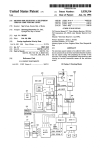
BRIEF DESCRIPTION OF THE DRAWING
FIG. 1 is a block diagram of a portion of a television
receiver suitable for implementing the invention.
Microcomputer 110 operates from a source of
standby power 145, and controls a source of operating
power 150 via a control line 151 for selectively applying
power to the remainder of the television receiver. Mi
crocomputer 110 also includes a timer 118. Microcom
puter (or controller) 110 generates a control signal for
causing tuner control unit 104 to control tuner 102 to
select a particular RF signal, in response to user-entered
control signals from local keyboard 120 and from infra
red (IR) receiver 122.
Tuner 102 produces a signal at an intermediate fre
quency (IF) and applies it to a processing unit 130 com
prising a video IF (VIF) amplifying stage, an AFT
circuit, a video detector, and a sound IF (SIF) amplify
ing stage. Processing unit 130 produces a ?rst baseband
composite video signal (TV), and a sound carrier signal.
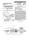
FIGS. 20-20 are illustrations of screen displays pro
The sound carrier signal is applied to an audio signal
duced in accordance with the invention.
FIGS. 30 and 3b are illustrations of channel labels 40 processor unit 135 which includes an audio detector and
may include a stereo decoder. Audio signal processor
displayed on screen.
unit 135 produces a ?rst baseband audio signal and
DETAILED DESCRIPTION OF THE DRAWING
applies it to a speaker unit 136. Second baseband com
posite video signals and second baseband audio signals
Referring to FIG. 1, a television receiver includes an
RF input terminal 100 which receives radio frequency 45 may be applied to VIDEO IN and AUDIO IN termi
nals from an external source.
(RF) signals and applies them to a tuner assembly 102.
The ?rst and second baseband video signals (TV) are
Tuner assembly 102 selects and ampli?es a particular
coupled to a video processor unit 155 (having a selec
RF signal under control of a tuner controller 104 which
provides a tuning voltage via a wire 103, and band
tion circuit not shown) Under control of controller 110,
switching signals via signal lines represented by the
50 an on-screen display processor 140 generates character
broad double-ended arrow 103', to tuner assembly 102.
signals and graphics signals, and applies them to a sec
ond input of video signal processor 155, for inclusion in
Tuner assembly 102 converts the received RF signal
to an intermediate frequency (IF) signal and provides an
IF output signal to video (V IF) and sound (SIF) ampli
?er and detector unit 130. VIF/SIF ampli?er and de
tector unit 130 ampli?es the IF signal applied to its input
the processed video signal. Electrically-erasable pro
grammable read only memory (EEPROM) 117 is cou
pled to controller 110, and serves as a non-volatile stor
age element for storing autoprogramming channel data,
and user-entered channel data.
The processed video signal at the output of video
signal processor unit 155, is applied to a Kine Driver
other input of video processor unit 155 is connected to 60 Ampli?er 156 for ampli?cation and then applied to the ‘
guns of a color picture tube assembly 158 for display.
an on-screen display and graphics processor circuit 140.
The processed video signal at the output of video signal
The detected audio signal is applied to an audio proces
processor unit 155, is also applied to a Sync Separator
sor 135 for processing and ampli?cation before being
terminal and detects the video and audio information
contained therein. The detected video information is
applied as one input of a video processor unit 155. The
unit 160 for separation of horizontal and vertical drive
applied to a speaker assembly 136.
Tuner controller 104 generates the tuning voltage 65 signals which are in turn applied to a deflection unit
170. The output signals from deflection unit 170 are
and bandswitching signals in response to control signals
applied to de?ection coils of picture tube assembly 158
applied from a system control microcomputer (PC) 110.
for controlling the de?ection of its electron beam. The
The terms “microcomputer”, controller, and “micro
3
5,253,067
television receiver described thusfar with the exception
of OSD and GRAPHICS PROCESSOR 140 is known,
for example, from the RCA CTC-l40 color television
manufactured by Thomson Consumer Electronics, Inc.,
4
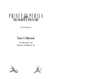
television network displayed in the upper right corner.
Data corresponding to this logo is stored in ROM and
generated by OSD and GRAPHICS PROCESSOR
unit 140. The procedure for associating a graphics logo
Indianapolis, Ind.
with a television channel is the same as that given above
The invention will now be described with reference
to the remainder of FIG. 1, the menu displays of FIGS.
for selecting a text label. That is, the user steps through
a list of preprogrammed text labels until he ?nds the
2a-2c, and the screen displays of FIGS. 3a and 3b.
proper one, for example NBC. Upon selecting NBC,
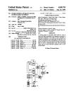
FIG. 2a shows a menu screen called up by a user
controller 110 causes OSD and GRAPHICS PROCES
wanting to enter a label for channel 11. To modify the
SOR unit 140 to substitute a preprogrammed graphics
logo, if one exists in memory, for the corresponding text
label.
A constructed and tested version of the invention
includes 108 preformed labels and memory space for 19
user-entered labels.
What is claimed is:
label, the user highlights the LABEL line by using the
+ and — keys of remote control unit 125 to move up
and down through the menu and by selecting the label
line by pressing its SELECT key. Then user then
presses the + and — keys to step through a prepro
grammed list of labels. FIG. 2b shows the prepro
grammed label NBC. If the user desires to enter the
1. A television receiver, comprising:
preprogrammed label NBC, he simply presses the SE
LECT key of remote control unit 125. If, on the other
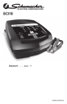
hand, the user cannot find an appropriate prepro 20
grammed label, then he steps through the list until he
?nds the label YOU ENTER. Upon selecting the YOU
means for entering data in response to operation by a
user;
memory means for storing data representative of a
preprogrammed label;
control means coupled to said memory means for
ENTER label, the user may enter his own label by
pressing the +, —-, and SELECT keys of remote con
reading said data from said memory means; and
on-screen display and graphics generator means cou
pled to said control means for producing text char
trol unit 125 until he has spelled the desired label. To
further illustrate this point, FIG. 2c shows a user
entered label USER"S LABEL, and FIG. 3b shows the
user-entered label displayed on the screen 3101) of a
television receiver 310a.
OSD and GRAPHICS PROCESSOR unit 140 of 30
acter video signals and graphics video signals for
display, said text character and graphics video
signals corresponding to said stored data;
said control means associating said stored data repre
sentative of a preprogrammed label with a televi
sion channel in response to data input by a user.
2. The apparatus of claim 1 wherein said prepro
grammed label is a network logo or service mark.
3. The apparatus of claim 1 wherein said prepro
PROCESSOR unit 140 via a digital control bus 131. 35
FIG. 1, includes the capability of producing high reso
lution graphics for display on the screen of picture tube
assembly 158, under control of controller 110. Control
ler 110 communicates with OSD and GRAPHICS
grammed label comprises text characters.
One of the capabilities of OSD and GRAPHICS PRO
CESSOR unit 140 is the ability to generate graphics
4. The apparatus of claim 1 wherein a portion of said
data entered by said user is data representative of an
alternative text label.
logos or service marks of various sizes on the screen.
FIG. 3a shows a television receiver 300a, having a
screen 3100 showing a video image with the logo a
it
45
55
65
i
t
t
#