1
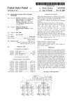
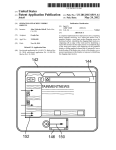
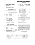
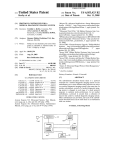
USOO8812082B2
(12) United States Patent
(10) Patent N0.2
Hajicek et al.
US 8,812,082 B2
(45) Date of Patent:
(54) AUTOMATICALLY SUPPLYING A
Aug. 19, 2014
20037060728814? 21* 2/2802 vovebllr
uc
1
0n et a .
.............. ..
604/151
PRESSURIZING UNIT OF A MEDICAL
2007/0100282 A1 *
5/2007 Small et al.
INJECTION DEVICE WITH FLUID
2008/0161757 A1 *
7/2008 Nayak et a1. .................. .. 604/82
(75) Inventors: David Hajicek, Minnetonka, MN (US);
604/151
FOREIGN PATENT DOCUMENTS
Richard Oftedahl, Jordan, MN (U S)
(73)
Assignee: ACIST Medical Systems, Inc., Eden
P
. .
MN
ralne,
_
(*)
S
(U )
_
Notlce:
_
_
_
EP
1 847 284 A1
10/2007
W0
01/74421 A1
10/2001
WO
2006/044409 A2
4/2006
wo
wo 2007/033103 A1
3/2007
W0
W0 2007/062315
5/2007
Subject to any disclaimer, the term of this
patent is extended or adjusted under 35
U'S'C' 15403) by 1413 days'
A3
OTHER PUBLICATIONS
Communication from European associate regarding responding to
the communication dated Jun. 14, 2011, under Rules 161/162, ?led
(21)
(22)
Appl' NO': 12/261’713
Filed
Oct 30 2008
.
.
(65)
,
(Continued)
Prior Publication Data
Us 2010/0113924 A1
(51)
with the European Patent Of?ce for European Patent Application No.
09744569.6-2319, dated Dec. 21, 2011, 20 pgs.
P '
May 6, 2010
Int_ CL
'
i T
5?
Ch
en
(74) Attorney, Agent, or Firm * Shumaker & Sieffert, P.A.
A61M 5/00
(2006.01)
A61M1/00
(2006.01)
(57)
A61M 5/3 6
(2006.01)
In general, this disclosure relates to techniques for automati
(52) US, Cl,
ABSTRACT
cally supplying a pressuriZing unit (e.g., syringe) that is used
CPC _ A61M 5/36 (2013.01); A61M 5/00 (201301);
(58)
E
Hind” xaml'ier
Asszstant Exammer * H1en Nguyen
with a powered medical ?uid injection device with ?uid. An
A61M1/00 (2013.01); A61M5/007 (2013.01)
example method performed by the medical ?uid injection
USPC ......................................... .. 600/432; 604/123
device includes obtaining operational state information of the
Field of Classi?cation Search
medical ?uid injection device, wherein the operational state
CPC _________ __ A61M 5/36; A61M 5/00; A61M 1/()();
information includes information other than a ?uid delivery
A61M 5/007
amount for a subsequent injection procedure. The example
USPC ........................................................ .. 600/432
method fuITher includes 11$ng the Operational state informa
See application ?le for complete search history
tion to determine whether the powered medical ?uid injection
device permits a ?uid replenishment operation for the pres
suriZing unit. If the ?uid replenishment operation is permit
ted, the method further includes automatically supplying the
(56)
References Cited
U.S. PATENT DOCUMENTS
5,573,515
6,221,045
6,626,862
6,932,242
7,128,729
A
B1
B1
B2
B2
11/1996
4/2001
9/2003
8/2005
10/2006
Wilson et a1.
Duchon et al.
Duchon et al.
Gerlach et al.
Duchon et a1.
pressuriZing unit with an amount of medical ?uid. 1f the
device includes multiple pressuriZing units, the device may
initiate an automatic ?uid replenishment procedure for one or
more of the pressuriZing units during operation.
30 Claims, 10 Drawing Sheets
US 8,812,082 B2
Page 2
(56)
References Cited
First Of?ce Action (with English Translation) and Search Report for
corresponding Chinese patent application No. 2009801446568,
dated Nov. 2, 2012, 12 pages.
OTHER PUBLICATIONS
International Preliminary Report on Patentability for international
application No. PCT/US2009/062384, dated Feb. 7, 2011, 11 pp.
Of?ce Action from Australian Application No. 2009314380, dated
May 10, 2012, 2 pp.
Reply to Written Opinion, ?led With the IPENEPO in corresponding
PCT Application No. PCT/US2009/062384, on Aug. 30, 2010 (11
Examination Report for corresponding Canadian patent application
No. 2,741,702, dated Jan. 11, 2013, 2 pages.
Of?ce Action from corresponding Korean Application No. 10-2011
7011092, With translation, dated Sep. 26, 2012, 7 pp.
Examiner’s Opinion stated in the Of?ce Action for corresponding
Japanese patent application No. 2011-534715, 1 page, Oct. 30, 2012.
Response to Examiner’s Report dated May 10, 2012, for correspond
ing Australian patent application No. 2009314380, dated May 30,
pgS)
2013, 16 pages.
Response to Examiner’ s Report dated Jan. 11, 2013, for correspond
Noti?cation of Transmittal of the International Search Report and the
Written Opinion of the International Searching Authority, or the
Declaration from corresponding PCT Application No. PCT/US2009/
ing Canadian application No. 2,741,702, dated Jul. 11, 2013.
Of?ce Action (with English Translation) for corresponding Korean
patent application No. 10-2011-7011092, dated Mar. 26, 2013, 6
062384, mailed Mar. 19, 2010 (12 pages).
pages.
“ACIST CVi Contrast Delivery System User Manual”, ACIST Medi
cal Systems, Inc., Nov. 2005, (91 pages).
* cited by examiner
US. Patent
Aug. 19, 2014
Sheet 1 0110
US 8,812,082 B2
.102
1AFIG.
US. Patent
Aug. 19, 2014
Sheet 2 0f 10
US 8,812,082 B2
mv.OE
US. Patent
Aug. 19, 2014
Sheet 3 0110
US 8,812,082 B2
2AFIG.
206
US. Patent
Aug. 19, 2014
Sheet 4 0f 10
US 8,812,082 B2
.GEmm
New
Pom
US. Patent
com
Aug. 19, 2014
mum
Sheet 5 0f 10
US 8,812,082 B2
o1N. "
(mFwN
ON.QE
SN
US. Patent
Aug. 19, 2014
Sheet 6 0f 10
US 8,812,082 B2
mva
.0EQN
US. Patent
Aug. 19, 2014
Sheet 7 0110
US 8,812,082 B2
306
304
3
FIG.3
US. Patent
Aug. 19, 2014
Sheet 8 0110
US 8,812,082 B2
N
O
\
406
400
f
416
418
408
FIG.4
US. Patent
Aug. 19, 2014
Sheet 9 0f 10
US 8,812,082 B2
RECEIVE USER INPUT
l—>
OBTAIN OPERATIONAL STATE
INFORMATION BY A PROCESSOR
r
500
f“ 501
<—
IF NECESSARY,
TERMINATE
CURRENT
REPLENISHMENT
OPERATION FOR
PRESSURIZING UNIT
502
OES OPERATIONAL STATE INFORMATIO
PERMIT REPLENISHMENT OF
PRESSURIZING UNIT?
USE STATE INFORMATION TO
K. 504
DETERMINE FLUID REPLENISHMENT
AMOUNT BY THE PROCESSOR
SUPPLY PRESSURIZING UNIT WITH
(- 506
DETERMINED FLUID AMOUNT
,- 508
INJECTOR OPERATIONAL STATE
CHANGES
FIG. 5
US 8,812,082 B2
1
2
AUTOMATICALLY SUPPLYING A
PRESSURIZING UNIT OF A MEDICAL
INJECTION DEVICE WITH FLUID
powered medical ?uid injection device includes obtaining
TECHNICAL FIELD
information other than a ?uid delivery amount for a subse
In one embodiment, an example method performed by a
operational state information of the medical ?uid injection
device, wherein the operational state information includes
quent injection procedure. The example method further
includes using the operational state information to determine
whether the powered medical ?uid injection device will per
mit a ?uid replenishment operation for a ?rst pressuriZing
unit. If the ?uid replenishment operation is permitted, the
method further includes automatically supplying the ?rst
This disclosure generally relates to the use of pressuriZing
units, such as syringes, within powered medical ?uid injec
tion devices.
BACKGROUND
medical ?uid into a patient. These devices often include one
pressuriZing unit with an amount of medical ?uid.
In one embodiment, an example medical ?uid injection
device includes a ?rst pressuriZing unit and an injector head
or more reservoirs to hold the medical ?uid, and one or more
that is con?gured to obtain operational state information of
Medical ?uid injection devices are typically used to inject
pressuriZing units to inject the medical ?uid into the patient.
For example, a contrast media powered injection device may
the device and use the operational state information to deter
mine whether a ?uid replenishment operation is permitted for
the ?rst pressuriZing unit, the operational state information
include a reservoir containing contrast media and a syringe
that is used to inject the contrast media into the patient. The
contrast media injection device may be used during certain
medical procedures, such as an angiographic or computed
including information other than a ?uid delivery amount for a
20
tomography (CT) procedure.
plies the ?rst pressuriZing unit with an amount of medical
?uid.
Many medical ?uid injection devices include one or more
syringes to inject ?uid. A syringe has a chamber for holding
the ?uid and a plunger that is moveable within the chamber.
The ?uid is typically drawn into the chamber from a ?uid
reservoir when the plunger is moved in a ?rst direction. The
subsequent injection procedure. If the ?uid replenishment
operation is permitted, the medical ?uid injection device sup
The details of one or more embodiments are set forth in the
25
accompanying drawings and the description below. Other
features, objects, and advantages will be apparent from the
description and drawings, and from the claims.
?uid is then expelled from the chamber and into the patient,
BRIEF DESCRIPTION OF DRAWINGS
via a catheter, when the plunger is moved in a second, oppo
site direction. The ?uid is delivered at a rate that may be
30
determined by a speed of movement of the plunger.
During a given medical procedure, a medical ?uid injec
FIG. 1A is a perspective diagram of one embodiment of a
powered medical ?uid injection device that may be used to
automatically supply a pressuriZing unit with ?uid.
tion device may need to deliver a determined amount of
medical ?uid. If the pressuriZing unit, such as a syringe, does
not contain a su?icient amount of ?uid for the procedure, a
clinician may need to interact with the device to initiate a ?uid
FIG. 1B is a perspective diagram of one embodiment of the
35
replenishment operation. For example, the clinician may
push a button or otherwise interact with a graphical user
interface (GUI) provided by the device to partially or com
pletely ?ll the pressuriZing unit. In other cases, the device
may be capable of calculating or otherwise determining an
amount of ?uid remaining within the pressuriZing unit, and
then supplying the pres suriZing unit with ?uid if it determines
that this remaining amount is less than the amount that is
required to perform an injection procedure for a patient.
40
45
powered medical ?uid injection device of FIG. 1A connected
to various components, including ?uid reservoirs and tubing.
FIGS. 2A-2D are various perspective diagrams of another
embodiment of a powered medical ?uid injection device that
may be used to automatically supply one or more pressuriZing
units with ?uid.
FIG. 3 is a perspective diagram of an example syringe that
may be used with a powered medical ?uid injection device,
according to one embodiment.
FIG. 4 is a perspective diagram of a patient line that may be
used with a powered medical ?uid injection device, according
to one embodiment.
SUMMARY
FIG. 5 is a ?ow diagram of a method that may be performed
by a powered medical ?uid injection device, according to one
In general, this disclosure relates to techniques for auto
matically supplying a pressuriZing unit (e.g., syringe) that is
embodiment.
50
used with a medical ?uid injection device with medical ?uid.
If the medical ?uid injection device includes multiple pres
suriZing units, the device may initiate an automatic ?uid
replenishment procedure for one or more of the pressuriZing
units during operation, as will be described in more detail
below. By automatically supplying a pressuriZing unit with
?uid at identi?ed times, the device is capable of preventing
the pressuriZing unit from running empty during a medical
procedure. The device may be capable of initiating a ?uid
replenishment operation without having to know or calculate
operation for one or more pressuriZing units.
55
DETAILED DESCRIPTION
60
powered medical ?uid injection device 100 that may be used
to automatically supply a pressuriZing unit contained within a
sleeve 108 with medical ?uid. In the embodiment of FIG. 1A,
the pressuriZing unit within sleeve 108 is a syringe. In other
embodiments, other forms of pressuriZing units may be used,
FIG. 1A is a perspective diagram of one embodiment of a
an amount of ?uid required for an injection procedure. As a
result, a user of the device, such as a clinician, may not need
to interact with the device to initiate a ?uid replenishment
cycle. In addition, there may be fewer interruptions during a
given medical procedure, and there may be opportunities to
perform a greater number of procedures in a given time period
due to higher operational ef?ciency of the device.
FIG. 6 is a conceptual diagram illustrating various opera
tional states during which time a powered medical ?uid inj ec
tion device may initiate an automatic ?uid replenishment
including other types of positive displacement pumps. Device
100 is, in some embodiments, used to inject medical ?uid,
65
such as contrast media or saline, into a patient during a medi
cal procedure, such as an angiographic or computed tomog
raphy (CT) procedure. Device 100 includes a control panel
US 8,812,082 B2
3
4
102, an injector head 104, a sleeve 108 to hold a pressuriZing
unit, a reservoir holder 110, a module 112, a patient manifold
sensor 114, and an air detector 116. Injector head 104
valve may comprise a spring-biased spool valve, but in other
embodiments, other types of valves, including check valves,
may also be used. Patient manifold sensor 114 can detect the
includes a pump 106 and also includes one or more processors
manifold valve position and report this position to injector
used to control and/ or monitor injector head 104, control
head 104 for safety purposes.
panel 102, the pressuriZing unit within sleeve 108, patient
Device 100 also includes air detector 116. Tubing that runs
from device 100 to an external catheter passes through air
manifold sensor 114, and air detector 116 of device 100.
Reservoir holder 110 is capable of holding a ?uid reservoir
that contains an amount of ?uid to be drawn into the syringe
detector 116, which is capable of detecting air bubbles or air
columns within the tubing. If air detector 116 detects a mea
sureable or otherwise signi?cant amount of air within the
during operation of device 100. For example, reservoir holder
110 may hold a reservoir of contrast media or diluent. A
tubing, it is capable of generating an alarm signal for injector
second reservoir holder (not shown) may hold a diluent (e.g.,
head 104. In such a case, a warning or alarm message may be
saline) for use in pump 106. FIG. 3 shows an example of a
displayed to the operator on control panel 102, indicating that
syringe that may be used within sleeve 108, according to one
air has been detected. In addition, in one embodiment, device
100 may automatically pause, or terminate, a ?uid injection
procedure if air detector 116 has detected air in the tubing,
such that the air is not delivered to the catheter.
Because device 100 may be used for many injections and
embodiment. Patient manifold sensor 114 may, in some
cases, be connected to a patient manifold, as will be described
in reference to FIG. 1B.
An operator of device 100, such as a clinician, may use
control panel 102 to set up various parameters and/or proto
cols to be used for a given injection procedure. For example,
the operator may interact with control panel 102 to enter
20
holder 110 becomes empty, it may need to be manually
replaced with a new (full) reservoir by the operator. In addi
tion, the syringe in sleeve 108 may need to be supplied with
injection ?uid from time to time, such that there is suf?cient
injection parameters for ?ow rate, maximum injection vol
ume, maximum injection pres sure, rise time, or other param
eters. In one embodiment, control panel 102 includes a touch
screen panel.
25
Pump 106 is capable of pumping ?uid. In one embodiment,
pump 106 is a peristaltic pump. In this embodiment, tubing
and a ?uid reservoir (not shown) are coupled to and through
the syringe has decreased or is low, the operator may initiate
a manual ?uid replenishment procedure by touching a button
on or otherwise interacting with control panel 102. By doing
30
In addition, device 100 is capable of automatically supply
35
within the syringe is moved in a ?rst direction by the motor,
?uid is drawn from the reservoir into the syringe. The syringe
within sleeve 108 is further coupled to output tubing. When
the plunger within the syringe is moved in a second, opposite
direction, ?uid is expelled out of the syringe into the output
tubing. In one embodiment, the syringe is a dual-port syringe,
such that the input tubing is coupled to one port of the syringe,
100 may determine this amount based upon volume informa
tion input by the operatorusing control panel 102. Device 100
may further determine an amount of ?uid remaining in the
40
syringe, such as by making a calculation of remaining ?uid
volume based upon amounts of ?uid injected from the
syringe. If the amount remaining in the syringe is less than a
maximum amount of ?uid to be delivered during an injection
procedure, device 100 can cause inj ector head 104 to add ?uid
45
and the output tubing is coupled to another port of the syringe.
FIG. 3 shows an example of such a dual-port syringe, which
will be described in more detail below.
Patient manifold sensor 114 is coupled to a manifold valve
amount of medical ?uid. In one such situation, device 100
may determine a maximum amount of ?uid that is to be
delivered during an injection procedure. For example, device
104. In one embodiment, injector head 104 includes a pro
cessor that drives the motor assembly.
In one embodiment, reservoir holder 110 holds a ?uid
reservoir that is coupled to input ?uid tubing. This input ?uid
tubing is coupled to the syringe, such that when the plunger
so, the operator may manually supply the syringe with ?uid
contained in the reservoir, either partially or completely.
ing the syringe, in certain situations, with a determined
a catheter. Pump 106 is driven by a motor that is part of pump
106, and the plunger within the syringe is driven by a motor
assembly, including an actuator, that is part of injector head
?uid within the syringe to perform injections for patient pro
cedures. When an operator detects that a ?uid volume within
pump 106. Pump 106 pumps ?uid from the ?uid reservoir
through the tubing towards module 112. In the example of
FIG. 1A, both pump 106 and the syringe contained within
sleeve 108 are capable of delivering ?uid from device 100 into
patient procedures, injection ?uids may need to be continu
ously replaced. For example, when the reservoir held by
50
to the syringe.
In one embodiment, injector head 104 of device 100 uti
lizes operational state information for device 100 in deter
mining whether or not a ?uid replenishment operation is
permitted for the syringe in sleeve 108. This operational state
information may comprise many different types of state infor
mation, but may include information other than an amount or
(not shown), according to one embodiment. This manifold
valve controls ?ow of ?uid from tubing coupled to either the
volume of ?uid that is to be delivered from the syringe for a
syringe in sleeve 108 or pump 106. In one embodiment, the
device 100 need not necessarily know how much ?uid may
need to be delivered from the syringe during an injection
manifold valve is coupled to output tubing from the syringe
subsequent injection procedure. That is, injector head 104 of
55
and also to tubing that runs through pump 106. Tubing also is
coupled between the manifold valve and air detector 116.
procedure in order to determine whether or not to initiate a
After passing through air detector 116, the tubing is then
utilize other operational state information in order to make
?uid replenishment operation. Instead, injector head 104 may
coupled to a patient line or catheter (not shown), such that
?uid can ultimately be delivered from device 100 to a patient.
The manifold valve held by the patient manifold sensor 1 14
such a determination.
60
is capable of controlling the ?ow of ?uid from the syringe and
operational state information may include, but are not limited
to, information related to any combination of the following
pump 106 to an external catheter. In one embodiment, the
manifold valve has a ?rst position that allows only ?uid from
the syringe to be delivered to the catheter. The manifold valve
has a second position that allows only ?uid from pump 106 to
be delivered to the catheter. In one embodiment, the manifold
Operational state information may include information
describing operating states or conditions of various portions
of a ?uid injection device, such as device 100. Examples of
65
operational states: (I) currently delivering/inj ecting ?uid
from a pressuriZing unit (e.g., “injecting”) (yes/no); (2) cur
rently delivering ?uid from a pump (yes/no); (3) armed (yes/
US 8,812,082 B2
6
5
no); (4) setup complete (yes/no); (5) air present (yes/no); (6)
FIG. 1B is a perspective diagram of one embodiment of the
powered medical ?uid injection device 100 of FIG. 1A con
valve position (e.g., spool valve) set to a speci?ed position
nected to various components, including ?uid reservoirs and
tubing. For example, FIG. 1B shows a ?rst ?uid reservoir 132
(positional value); (7) pressuriZing unit/syringe full; and (8)
auto ?uid supply mode (on/off). As these examples illustrate,
and a second ?uid reservoir 138. First ?uid reservoir 132
contains a ?rst ?uid, such as contrast media. An operator may
hang ?rst ?uid reservoir 132 on reservoir holder 110. In some
operating state information may, in some cases, have a ?nite,
relatively small number of values associated with certain
states. For example, the state of “currently delivering/inject
ing ?uid from the pressuriZing unit” can only have a value of
cases, ?rst ?uid reservoir 132 may be a glass reservoir, while
in other cases, it may be a plastic reservoir. The ?uid con
Yes or No. It is possible that some types of operational state
tained within ?rst ?uid reservoir 132 may be drawn through
tubing and into a pressuriZing unit 130 (e.g., a syringe) that
has been inserted into sleeve 108 during operation. During an
automatic replenishment operation, device 100 may auto
matically supply pressuriZing unit 130 with an amount of
?uid from ?rst ?uid reservoir 132.
information can have more than 2 values for a given opera
tional state. For example, a three-position switch may have
any of three different state values, and a valve having more
than two possible positions may also have multiple different
state values (depending on the position of the valve). The
operational state information could thus be used to de?ne a
Second ?uid reservoir 138 may contain a second ?uid, such
as saline. An operator may hang second ?uid reservoir 138 on
logic table (e.g., a set of rules) that determines, for a given
combination of operating states or conditions, whether a ?uid
a hook 137. In some cases, second ?uid reservoir 138 may be
replenishment operation is permitted, and may also automati
cally initiate such a replenishment operation. Each pressur
iZing unit (e.g., syringe, pump) that is used within the device
a plastic reservoir, such as a bag. The ?uid contained within
20
FIG. 1B also shows that a hand-control device 136 is
coupled to control panel 102 via a connector 134. In one
embodiment, hand-control device 136 may be connected to
may have its own associated operational state information.
For example, if injector head 104 uses operational state
information to determine that device 100 is currently deliv
ering ?uid from pump 106 but not from the syringe contained
in sleeve 108, injector head 104 may use this state information
to determine that it is permitted to automatically supply the
syringe with medical ?uid, if necessary (provided that the
auto ?uid supply mode parameter is set to “on”). That is, if the
syringe is not currently delivering ?uid, injector head 104
25
30
is currently full, injector head 104, of course, would not need
to initiate a ?uid replenishment procedure. But, if the syringe
35
determined amount of ?uid. In one scenario, injector head
40
In one embodiment, a known or determined amount of
?uid may be supplied to the syringe during a replenishment
operation. In one embodiment, device 100 may cause replen
ishment of the syringe when the amount remaining in the
syringe is below the maximum amount of ?uid to be delivered
during an injection procedure by a threshold amount (e. g., to
limit excessive ?uid replenishment operations). In one
embodiment, replenishing of the syringe with ?uid may occur
when the amount of ?uid remaining in the syringe is less than
a certain level (or less than a speci?ed amount of remaining
45
device to variably control the rate of ?ow of ?uid from device
100 (e.g., ?ow of ?uid out of pressuriZing unit 130). In one
embodiment, hand-control device 136 may comprise an elec
trical device. In one embodiment, hand-control device 136
may comprise a pneumatic device.
Tubing 128 is coupled to a pressure transducer 126. Pres
sure transducer 126 is also coupled to output, high-pressure
tubing 122, which may be connected to a patient line via
connector 120. When high-pressure tubing 122 is connected
to a patient line (within a patient), pressure transducer 126 is
capable of functioning as a hemodynamic monitor for the
patient. Pressure transducer 126 converts detected pressures
into electrical signals that may be monitored or otherwise
used by device 100 or another monitoring device. High-pres
sure tubing 122 also runs through air detector 116. Air detec
tor 116 is capable of detecting the presence of air (e.g., air
bubbles or columns) within ?uid that may be ?owing through
50
high-pressure tubing 122.
FIG. 1B also shows a manifold valve 124. This manifold
valve 124 is connected to high-pressure tubing 122, as well as
patient manifold sensor 114. Manifold valve 124 is capable of
controlling a ?ow of ?uid from pressuriZing unit 130 and/or
?uid), e.g., when the amount remaining in the syringe is less
than a determined percentage of the capacity of the syringe, or
less than a determined percentage of the maximum amount.
User-selectable parameters may be used to specify threshold
operator may manipulate hand-control device 136 to control
injection of ?uid from device 100. For example, the operator
may use hand-control device 136 as a variable-rate control
is not full, injector head 104 may actuate a motor/actuator
104 may decide to completely ?ll the syringe to capacity.
Thus, if the syringe is a 100 milliliter (ml) syringe and is
currently half full of medical ?uid, injector head 104 may ?ll
syringe to a full 100 ml capacity. In one scenario, injector
head 104 may only partially ?ll the syringe with ?uid.
another component of device 100 other than control panel
102.As shown in FIG. 1B, hand-control device 136 is coupled
to tubing, cabling, or wiring, which connects hand-control
device 136 to connector 134. Connector 134 may then be
connected to or disconnected from control panel 102. An
may cause the syringe to be supplied with ?uid. If the syringe
assembly coupled to the syringe to supply the syringe with a
second ?uid reservoir 138 may be drawn through tubing 128
through operation of pump 106.
55
through pump 106 to high-pressure tubing 122. For example,
amounts or determined percentages.
in one embodiment, when manifold valve 124 is in a ?rst
In one embodiment, device 100 may dynamically termi
nate a ?uid replenishment procedure of the syringe if the
operational state of device 100 changes such that a replenish
60
position, ?uid may ?ow from pressuriZing unit 130 to high
pressure tubing 122. When manifold valve 124, however, is in
a second position, ?uid may ?ow through pump 106, via
tubing 128, to high-pressure tubing 122. In one embodiment,
ment operation is no longerpermitted. For example, if, during
manifold valve 124 may allow ?uid ?ow to high-pressure
tubing 122 from only one of pressuriZing unit 130 or pump
a ?uid replenishment cycle, the operator wishes to initiate an
injection of ?uid from the syringe, injector head 104 may
terminate the ?uid replenishment cycle and begin an injection
procedure for injection of ?uid from the syringe. Additional
examples and embodiments pertaining to automated ?uid
replenishment operations will be further described in more
detail below.
106 at a time.
65
FIG. 2A is a perspective diagram of another embodiment of
a powered injection device 200 that may be used to perform
various functions and, when operable, may initiate an auto
mated ?uid replenishment operation. In FIG. 2A, device 200
US 8,8l2,082 B2
7
8
includes a ?rst primary reservoir holder 202A, a second pri
mary reservoir holder 202B, an electrical connection inter
face 206, a ?rst backup reservoir holder 208A, a second
backup reservoir holder 208B, a control panel 212, a ?rst
syringe sleeve 216A, a second syringe sleeve 216B, a ?rst
devices separate from device 200. In one embodiment, the
larger control panel looks similar to control panel 102 shown
in FIG. 1A.
Device 200 is a dual-syringe device that includes two
syringes contained within sleeves 216A and 216B. Both
syringes are capable of delivering medical ?uid to a patient.
In one embodiment, the syringe within sleeve 216A is
capable of drawing in ?uid from a ?uid reservoir coupled to
holder 202A, and the syringe within sleeve 216B is capable of
drawing in ?uid from a ?uid reservoir coupled to holder
202B. For example, these syringes may draw in ?uid during a
?uid replenishment operation. Each syringe is coupled to a
motor/ actuator assembly (not shown) that drives a plunger in
one of two directions. During a ?uid replenishment cycle, for
example, a motor/ actuator assembly of device 200 may drive
front-end assembly 218A, a second front-end assembly
218B, and a patient connection guide rod 220. In the embodi
ment of FIG. 2A, the pres suriZing units that are used to deliver
medical ?uid are syringes that are contained within sleeves
216A and 216B. Injector head 201 includes reservoir holder
202A, reservoir holder 202B, connection interface 206, res
ervoir holder 208A, reservoir holder 208B, and control panel
212. Injector head 201 further includes one or more proces
sors used to control and/ or monitor the components of inj ec
tor head 201 and other components of device 200.
Reservoir holder 202A is capable of holding a ?rst reser
a plunger within the syringe in sleeve 216A in one direction to
draw ?uid from a reservoir coupled to holder 202A into the
voir of medical ?uid, while reservoir holder 202B is capable
of holding a second reservoir of medical ?uid. In one embodi
ment, reservoir holder 202A holds a reservoir of a ?rst type of
?uid, such as contrast media, while reservoir holder 202B
holds a reservoir of a second, different type of ?uid, such as a
20
device 200 contains two distinct motor/actuator assemblies,
such that one assembly drives the syringe within sleeve 216A
while another drives the syringe within sleeve 216B. These
motor/ actuator assemblies are part of injector head 201, and
diluent (e.g., saline). Different forms of reservoirs (e.g.,
bottles, bags) may be used with reservoir holders 202A and
202B. Because device 200 may be used to inject medical ?uid
over multiple patient procedures, the reservoirs held by hold
25
ers 202A and 202B may need to be replaced over time. Typi
216A and 216B to the ?uid reservoirs and to output lines,
according to one embodiment. In one embodiment, the
device 200 additionally includes backup holders 208A and
30
202A or 202B runs empty and needs to be replaced, operator
may quickly and easily access a new ?uid reservoir from one
of backup holders 208A or 208B and attach to primary holder
202A or 202B.
200 to such an imaging device. In one embodiment, device
200 may transmit injection and/or control information to an
external imaging device via interface 206, and may receive
imaging and/or control information from the external imag
ing device via interface 206, as well.
FIG. 2A shows that device 200 also includes control panel
212. Control panel 212 is located on the top side of example
device 200. The operator may interact with control panel 212
to program various injection procedure parameters and/or
protocols that may be used for injection procedures. The
Front-end assembly 218A is associated with sleeve 216A,
and front-end assembly 218B is associated with sleeve 216B.
40
45
contents of the assembly 218A or 218B even when the door is
50
218B includes air detectors and valve components (not
shown). Air detectors are used to detect air bubbles or air
columns within the ?uid tubing that is used. The valve com
ponents are used to allow or restrict ?uid ?ow through tubing.
For example, when pinch valves are used, the valves pinch
55
ume, pressure, rise time, procedure type, ?uid information,
60
activated screen.
?uid tubing to restrict ?uid ?ow in one state, but stay open to
allow ?uid ?ow in another state. Various different forms of
valves may be used within assemblies 218A and 218B. In
addition, various different forms of air detectors (e.g., ultra
sonic, optical) may be used, as well.
In one embodiment, the input and output tubing that is
coupled to the syringe in sleeve 216A runs through front-end
assembly 218A, and the input and output tubing that is
In one embodiment, a separate, larger control panel (not
shown) may also be in communication with device 200. In
this embodiment, the larger control panel provides similar
operator functionality to that provided by control panel 212.
embodiment, each door may be made of a transparent or
translucent material, such that the operator may see inside the
closed.
In one embodiment, each front-end assembly 218A and
various injection-related information (such as ?ow rate, vol
and/ or patient information). FIG. 2A shows various user
activated buttons on the side of control panel 212. However, in
one embodiment, control panel 212 may include a touch
Output tubing from the syringe in sleeve 216A runs through
assembly 218A and out to a patient line, while output tubing
from the syringe in sleeve 216B runs through assembly 218B
and out to the patient line. Each assembly 218A and 218B
includes a door, or cover, which may be opened and closed by
the operator. For the example, the operator may open the door
when loading tubing and may be closed upon loading. In one
operator may also use control panel to set up device 200 for
use, to begin, pause, resume, or end a procedure, or to view
syringes each are dual-port syringes (such as the dual-port
syringe shown in FIG. 3). In this embodiment, one syringe
port is used for input tubing that is coupled to a ?uid reservoir,
while the second port is used for output tubing that is opera
tively coupled to an output (patient) line through assemblies
35 218A or 218B.
Device 200 includes electrical connection interface 206 to
directly or indirectly couple device 200 to an external medical
device, such as a medical imaging device. Typically, device
200, when used as a contrast media injection device, works in
conjunction with a medical imaging device. For example,
device 200 may work in conjunction with a medical imaging
device during an angiographic or CT procedure. Connection
interface 206 is used to directly or indirectly connect device
may individually be controlled or monitored by the one or
more processors included within injector head 201.
Fluid input tubing couples the syringes within sleeves
cally, an operator of device 200 manually replaces the reser
voirs on holders 202A and 202B. For operator convenience,
208B. The operator may store backup ?uid reservoirs on
holders 208A and 208B. When a reservoir on primary holder
syringe. During an injection cycle, the motor/ actuator assem
bly of device 200 may drive the plunger within this syringe in
the opposite direction to expel ?uid. In one embodiment,
coupled to the syringe in sleeve 216B runs through front-end
assembly 218B. In this embodiment, each assembly 218A
65
and 218B contains a ?rst pinch valve and a ?rst air detector
However, the larger control panel may be mounted to a rail of
coupled to the input tubing for the respective syringe, and
a bed on which a patient is lying, or may be mounted to other
further contains a second pinch valve and a second air detec
US 8,812,082 B2
10
tor coupled to the output tubing for the respective syringe.
a button or actuates a component, the greater the ?ow rate of
These components are more clearly shown in FIG. 2D and
will be discussed in more detail below.
injected ?uid from the syringe in sleeve 216A or 216B.
FIG. 2C is another perspective diagram of device 200. FIG.
2C shows a top view of device 200, according to one embodi
FIG. 2A also shows a patient connection guide rod 220.
The output tubing from syringes 216A and 216B run through
front-end assemblies 218A and 218B, respectively, and are
then coupled to a patient line, or kit (not shown). The patient
line is a single-use line, according to one embodiment, that is
used for a single patient procedure. Each patient line may be
ment.
FIG. 2C also shows doors 221A and 221B on front-end
assemblies 218A and 218B, respectively. As noted above, in
one embodiment, each of assemblies 218A and 218B include
a moveable door 221A and 221B, respectively. Door 221A
covers assembly 218A, and door 221B covers assembly
218B. In the embodiment of FIG. 2C, doors 221A and 221B
are made of a transparent, or semi-transparent, material, such
that an operator may see the contents of assemblies 218A and
218B (which are shown in more detail in FIG. 2D). Door
221A includes a handle 219A, and door 221B includes a
handle 219B. The operator may utilize handles 219A and
219B to open and close doors 221A and 221B, respectively.
connected to and disconnected from the output tubing run
ning through front-end assemblies 218A and 218B. The
patient line is connected to the output tubing via connection
guide rod 220, according to one embodiment. The patient line
may slide over connection guide rod 220 in order to become
coupled with the output tubing. In one embodiment, the
patient line includes two tubing elements, each element cor
responding to one of the output tubing elements of the syringe
in sleeve 216A or 216B. An example patient line is shown in
FIG. 4 and will be discussed in more detail below.
In one embodiment, a medical ?uid injection device, such
Doors 221A and 221B are coupled to one or more hinges 228,
20
inserted through hinges 228, according to one embodiment,
as device 200, may include a plurality of pressuriZing units,
including three or more pressuriZing units. Each of these
pressuriZing units may be included within a separate sleeve
during operation. In some cases, multiple pressuriZing units
may contain the same type of ?uid. For example, a ?rst
pressuriZing unit may contain contrast media, a second pres
suriZing unit may contain a diluent (e.g., saline), and a third
pressuriZing unit may contain contrast media. In this sce
nario, the third pressuriZing unit may comprise a backup, or
secondary, source of contrast media. In this example, the ?rst
25
30
and third pressuriZing units may both be coupled to a common
front-end assembly, such as a front-end assembly similar to
operator may choose to remove doors 221A and 221B if the
35
with front-end assemblies 218A and 218B, can be more
clearly seen. Although the doors of assemblies 218A and
218B are closed in the example of FIG. 2B, they are made of
a semi -transparent material, such that the interior pinch valve
and air detector components may be more clearly seen. FIG.
2B also shows connection ports 222 and 224. In one embodi
ment, a pressure transducer connector (such as one coupled to
connector 410 shown in FIG. 4), may be connected to con
nection port 224. The pressure transducer connector is opera
tively coupled to a pressure transducer, which measures
40
and a second air detector 236A. Input tubing from a reservoir
on holder 202A runs through air detector 230A and pinch
valve 232A and into a syringe in sleeve 216A via a ?rst
45
syringe port, according to one embodiment. Output tubing
coupled to a second syringe port of the syringe in sleeve 216A
runs through pinch valve 234A and air detector 236A and is
ing a pressure transducer to connection port 224, device 200
is capable of utiliZing and processing hemodynamic pressure
tion of one or both of syringes in sleeves 216A and 216B. For
example, the operator may push a button or otherwise interact
218A and 218B shown in more detail, according to one
embodiment. Although doors 221A and 221B are not shown
in FIG. 2D, they are made of a transparent, or semi-transpar
ent, material, such that the contents of assemblies 218A and
218B may be more clearly seen by an operator, even when
doors 221A and 221B are closed.
Front-end assembly 218A includes a ?rst air detector
230A, a ?rst pinch valve 232A, a second pinch valve 234A,
patient hemodynamic signals on the patient line. By connect
signals of a patient that are detected in the patient line.
Device 200 also includes connection port 222, which may
be connected to a hand-control device (not shown). In one
embodiment, the hand-control device is a disposable compo
nent that may be used by the operator for a single patient
procedure. The hand-control device may control the opera
to securely allow doors 221A and 221B to be freely opened
and closed by an operator. Doors 221A and 221B pivot about
an axis that runs through pivot pin 229.
In one embodiment, pivot pin 229 is screwed into place.
Pivot pin 229 may also be removed by an operator. For
example, the operator may unscrew pivot pin 229 and remove
it from front-end assemblies 218A and 218B. After pivot pin
229 has been removed, doors 221A and 221B may also be
removed from assemblies 218A and 218B. For example, the
operator wishes to clean or replace doors 221A and 221B.
FIG. 2D is a perspective view of front-end assemblies
218A or 218B.
FIG. 2B is another perspective diagram of device 200
shown in FIG. 2A. In FIG. 2B, sleeves 216A and 216B, along
which allow doors 221A and 221B to be opened and closed.
Also shown in FIG. 2C is a pivot pin 229. Pivot pin 229 is
50
then coupled an external patient line, or kit (such as the one
shown in FIG. 4). Air detector 230A is used to detect air
bubbles or columns within the input tubing, and air detector
236A is used to detect air bubbles or columns within the
output tubing. Air detectors 230A and 236A may comprise
acoustic-based, optical-based, or other forms of air detectors.
If either or both of air detectors 230A and 236A detect a
55
measurable amount of air in the input and/or output tubing,
these detectors may propagate signals to injector head 201 of
with the hand-control device to cause a motor/ actuator assem
device 200. One or more processors of inj ector head 201 may
bly to inject ?uid from the syringe in sleeve 216A, and may
process these received signals. Injector head 201 may provide
push another button or otherwise interact with the hand
control device to cause a motor/actuator assembly to inject
a warning message or alert to the operator via control panel
60
212, such that the operator may take appropriate action. Inj ec
tor head 201 may also, in one embodiment, automatically
pause or terminate any injection of ?uid from the syringe in
sleeve 216A if air has been detected in the input and/ or output
tubing, by controlling operation of the motor/ actuator assem
65
bly driving the syringe.
?uid from the syringe in sleeve 216B. Thus, if the syringe in
sleeve 216A contains contrast media, and the syringe in
sleeve 216B contains a diluent, the operator may push one
button on the hand-control device to inject contrast into the
patient line, and may push another button to inject saline. In
one embodiment, the hand-control device contains variable
rate functionality, such that the harder the operator pushes on
Pinch valve 232A controls a ?ow of ?uid from input tubing
into the syringe in sleeve 216A. Injector head 201 controls the
US 8,812,082 B2
11
12
For example, injector head 201 may obtain operational
operation of pinch valve 232A. When injector head 201 opens
state information at a given point in time to determine that
pinch valve 232A, ?uid may ?ow from the reservoir con
nected to holder 202A and into the syringe. When pinch valve
232A is closed, no ?uid ?ow is permitted within the input
device 200 is injecting ?uid from the syringe in sleeve 216A,
but is not injecting ?uid from the syringe in sleeve 216B.
Given this operational state information, injector head 201
tubing. For example, when injector head 201 is supplying the
syringe with ?uid, it may open pinch valve 232A to allow
?uid ?ow in the input tubing, but it may also close pinch valve
234A, to prohibit any ?uid ?ow in the output tubing. The
plunger within the syringe may be moved in a ?rst direction
(by the motor/actuator assembly) to supply ?uid to the
syringe. When a ?uid injection occurs, the motor/actuator
may then be able to determine that it can supply the syringe in
assembly will move the plunger within the syringe in a sec
201 need not initiate a ?uid replenishment operation, since it
determines that a supply amount would essentially be equal to
zero. If, however, the syringe is not full to capacity, injector
head 201 may supply the syringe in sleeve 216B with a
determined amount of ?uid. For example, injector head 201
may cause the syringe to be completely ?lled to capacity. Or,
injector head 201 may otherwise use operational state infor
sleeve 216B with ?uid, if necessary, given that this syringe is
not currently being used to inject ?uid. Injector head 201 may
?rst check to see if this syringe is already full, such as by
checking additional operational state information or by mak
ing a calculation. If the syringe is already full, injector head
ond, opposite direction. Injector head 201 may close pinch
valve 232A during an injection procedure, to prohibit ?uid
?ow in the input tubing. However, injector head 201 may
open pinch valve 234A, to allow ?uid ?ow in the output
tubing during such a procedure. In such fashion, injector head
201 utilizes pinch valves 232A and 234A to control ?uid ?ow
in the input and output tubing during various operations (e.g.,
replenishment and injection operations).
mation to determine an amount of ?uid to use during the ?uid
20
Injector head 201 may determine whether the syringe in
sleeve 216B is already full using a number of different
In one embodiment, pinch valves 232A and 234A are sole
noid-based pinch valves. In other embodiments, other forms
of pinch valves 232A and 234A may be used, such as pneu
matic-based valves. In one embodiment, pinch valves 232A
and 234A have default states in the closed position. Thus,
when device 200 is neither supplying ?uid into nor injecting
replenishment operation.
approaches. For example, in one scenario, injector head 201
may use operational state information to determine how much
25
?uid remains in the syringe. In another scenario, injector head
?uid from the syringe in sleeve 216A, both pinch valves 232A
201 may calculate an amount of remaining ?uid based upon
an amount of ?uid that has been injected from the syringe in
and 234A are closed. Pinch valves 232A and 234A may then
prior injection procedures, which may also be obtained from
be opened by device 200 when energy is actively applied to
pinch valves 232A and/or 234A. When no energy is applied to
pinch valves 232A and/ or 234A, they return to a default,
closed position. Thus, if there are any power failures to device
200, valves 232A and 234A will return to closed position.
operational state information of device 200. Operational state
30
device 200, including operational information, injection
parameters used, error messages, alert conditions, and any
other related information.
Using another example, injector head 201 may also gather
This may help improve the safety of device 200.
Similarly, front-end assembly 218B includes a ?rst air
detector 230B, a ?rst pinch valve 232B, a second pinch valve
234B, and a second air detector 236B. Input tubing from a
35
40
syringe port of the syringe runs through pinch valve 234B and
45
of initiating ?uid replenishment cycles for the syringes in
tion for one or both of the syringes. If a ?uid replenishment
in sleeve 216A with ?uid, but detects that the operator now
wants to initiate an injection procedure using ?uid from this
50
its processors to perform certain operations.
55
example, when a syringe delivers ?uid to a catheter in a
patient, a clinician may inject intermittent, frequent “puffs” of
60
to know an amount of ?uid that is to be injected from the
syringe in sleeve 216A or 216B for a patient injection proce
with ?uid.
contrast media from device 200 during placement of the
catheter within the patient. In this example, it may sometimes
be bene?cial to avoid, or prohibit, replenishment operations
in between these “puff” injections. Thus, a ?uid replenish
ment operation may, in some cases, only be permitted if a
dure in order to determine whether or not to allow and initiate
effective and ef?cient way by which to supply the syringes
In one embodiment, a ?uid replenishment operation may
be permitted if at least a determined amount of time has
elapsed since a prior injection of medical ?uid from one of the
pressuriZing units (e. g., syringes) in sleeve 216A or 216B. For
embodiment, such that device 200 need not necessarily need
a ?uid replenishment operation. This may provide a more
syringe, injector head 201 will stop the ?uid replenishment
operation and initiate an injection operation. During any of
these operations, injector head 201 may utilize one or more of
operation is permitted for one of these syringes, injector head
201 then initiates a ?uid replenishment operation with a deter
mined amount of medical ?uid. The operational state infor
mation includes information other than a ?uid delivery vol
ume for a subsequent injection procedure, according to one
216A or 216B with ?uid, it continually monitors the state of
device 200, according to one embodiment. If the state of
device 200 changes, injector head 201 may pause or abort a
?uid replenishment operation that is taking place. For
example, if device 200 is automatically supplying the syringe
In one embodiment, device 200 of FIGS. 2A-2D is capable
sleeves 216A and/ or 216B during different operational states
of device 200. In this embodiment, injector head 201 may
obtain operational state information for the device, such as,
for example, the type of operational state information
described with reference to FIGS. 1A-1B. Injector head 201
then is capable of using the operational state information to
determine whether it will permit a ?uid replenishment opera
more subsequent procedures to be performed. In this case,
injector head 201 may initiate a ?uid replenishment operation
for both of the syringes.
When injector head 201 is supplying the syringe in sleeve
air detector 236B, and may then be coupled to a patient line.
The components within device 218B function similarly to
those contained within device 218A as described above,
according to one embodiment.
operational state information indicating that neither of the
syringes in sleeves 216A or 216B is being used to inject ?uid
at a given time. This may be the case when an operator is using
control panel 212 to set up injection parameters for one or
reservoir connected to holder 202B runs through air detector
230B and pinch valve 232B and into a ?rst syringe port of the
syringe in sleeve 216B. Output tubing coupled to a second
information includes current and past state information about
65
determined amount of time (e.g., 30 seconds) has elapsed
since a prior injection, or “puff,” of contrast media. In some
cases, a ?uid replenishment operation may be permitted if a
US 8,812,082 B2
13
14
?uid volume in the syringe has decreased at least a deter
mined amount since a prior replenishment operation was
a connector 310, which may be connected to a ?uid reservoir
performed.
216A. For example, if connector 310 is a spike, the spike may
in holder 202A, assuming syringe 301 is loaded into sleeve
Table 1 below shows examples of a number of different
be inserted into a bottle of medical ?uid connected to holder
states of operation of device 200 during which one or more
202A. Output tubing 304 is coupled to a connector 306, which
couples output tubing 304 to a separate patient line. In one
?uid replenishment operations of the syringes in sleeves
216A and 216B may be initiated. From the examples shown
in Table 1, it is assumed that the syringe in sleeve 216A is used
for injecting contrast media and that the syringe in sleeve
216B is used for injecting saline, which is a diluent. Addi
tional states and/or operations to those listed may also be
may run through air detector 230A and pinch valve 232A
possible.
(FIG. 2D) of front-end assembly 218A, which was described
embodiment, connector 306 is a Luer-type connector.
Fluid is drawn from the ?uid reservoir into port 300 of
syringe 301 via input tubing 308. Fluid is expelled from port
302 of syringe 301 into output tubing 304. Input tubing 308
TABLE 1
STATE OF INJECTION DEVICE 200
Contrast media purge from syringe in sleeve
FLUID REPLENISHMENT
OPERATION
Supply saline to syringe in sleeve 216B
216A
Saline purge from syringe in sleeve 216B
Supply contrast media to syringe in sleeve
216A
Contrast media injection from syringe in
Supply saline to syringe in sleeve 216B
sleeve 216A
Saline injection (or KVO cycle) from syringe Supply contrast media to syringe in sleeve
in sleeve 216B
216A
Injection parameter entry/change by operator Supply contrast media to syringe in sleeve
on control panel 212
216A and/or supply saline to syringe in
sleeve 216B
Standby mode for device 200
Supply contrast media to syringe in sleeve
216A and/or supply saline to syringe in
sleeve 216B
Contrast media reservoir change by operator
Supply saline to syringe in sleeve 216B
(such as by replacing reservoir on holder
202A)
Saline reservoir change by operator (such as
by replacing reservoir on holder 202B)
Supply contrast media to syringe in sleeve
216A
In the examples of Table 1, purge operations from the
35
syringes in sleeves 216A and/or 216B occur when device 200
in more detail above, while output tubing 304 may run
through pinch valve 234A and air detector 236A. In one
is being primed, or prepared, for patient use. Thus, during
embodiment, syringe 301, along with input tubing 308, con
purge operations, device 200 is not yet connected to a patient.
nector 310, output tubing 304, and connector 306, are dispos
able, multi-use components. That is, these components may
Conversely, during injection operations from the syringes,
?uids are injected into a patient. Device 200 may also be used
40
for KVO, or “keep vessel open”, operations. A KVO opera
be used within device 200 over multiple uses or patient pro
cedures before they are disconnected from device 200 and
tion occurs when small amounts of diluent are repeatedly or
disposed of. In another embodiment, these components are
continuously injected. Also in reference to Table 1, device
200 may be in standby mode when neither syringe is being
used to inject ?uid. For example, device 200 may enter
disposable, single-use components, meaning that they are
disposed of after a single patient procedure.
45
In one embodiment, syringe 301 may also be used in device
100 (FIG. 1A). When used in device 100, connector 310
standby mode after a patient case has been ?nished, and
before the operator has entered parameters or otherwise con
?gured the device using panel 212 for a new case. In one
embodiment, the examples shown in Table 1 are based upon
would be connected to a ?uid reservoir on holder 110, and
output tubing 304 would run through patient manifold sensor
50
an assumption that only one of the contrast media or diluent is
injected at a time.
In some cases, during an automatic ?uid replenishment
operation, a user or operator may intervene by interacting
with the control panel, such as control panel 102 (FIG. 1A) or
control panel 212. For instance, an operator may choose to
55
connector 404. When assembly 401 is coupled to device 200,
60
ment. Syringe 301 may be loaded in either sleeve 216A or
216B. If syringe 301 is loaded into sleeve 216A, it may be
coupled to a ?uid reservoir connected to holder 202A (FIG.
2A), and may further be coupled to a patient line (FIG. 4).
Syringe 301 is a dual-port syringe in the example of FIG. 3.
Input port 300 is coupled to input tubing 308, and output port
302 is coupled to output tubing 304. Input tubing is coupled to
may be used with injection device 200 shown in FIGS.
2A-2C, according to one embodiment. Patient line 400
includes an assembly 401, a valve 416, a stopcock 418, and a
connector 420. Patient line 400 is used to couple device 200
with a catheter that is used to deliver medical ?uid to a patient.
Assembly 401 includes a ?rst connector 402 and a second
terminate a ?uid replenishment operation, or may choose to
modify one or more ?uid supply parameters.
FIG. 3 is a perspective diagram of an example syringe 301
that may be used within device 200, according to one embodi
114.
FIG. 4 is a perspective diagram of a patient line 400 that
connector 402 is connected with a connector for output tubing
that is coupled to one of the syringes in sleeves 216A or 216B,
while connector 404 is connected with a connector for output
tubing that is coupled to the other syringe. For example,
connector 402 may be connected to connector 306 (FIG. 3),
which is coupled to output tubing 304 for the syringe in sleeve
65
216A. Patient line 400 is a disposable kit, in one embodiment,
such that connectors 402 and 404 may be connected to and
removed from tubing connectors, such as connector 306, by
US 8,812,082 B2
15
16
the operator. In one embodiment, patient line 400 is a single
use disposable kit, such that it is connected to device 200 for
one patient use, and then subsequently disconnected and dis
carded.
mation. The operational state information may include cur
rent or prior state information, along with current or prior
operational information for device 100 or device 200. At 502,
device 100 or device 200 may determine whether the opera
tional state information permits a ?uid replenishment opera
tion for one or more pressuriZing units. For example, device
100 may determine whether such information permits a ?uid
Connector 402 is operatively coupled to tubing 406, and
connector 404 is operatively coupled to tubing 408. In one
embodiment, connector 402 is coupled to the syringe in
sleeve 216A, which contains contrast media, while connector
404 is coupled to the syringe in sleeve 216B, which contains
replenishment operation of the syringe in sleeve 108, while
device 200 may determine whether such information permits
a ?uid replenishment operation of syringe in sleeve 216A
a diluent such as saline. Thus, in this embodiment, contrast
media is injected into tubing 406 of patient line 400, while
and/or 216B. In many cases, a ?uid replenishment operation
will be allowed if a given pressuriZing unit is not currently
being used to inject or purge any ?uid.
If a ?uid replenishment operation is not permitted (such as,
diluent is injected into tubing 408. Tubing 406 and 408 are
coupled to valve 416, which, in one embodiment, comprises
an elastomeric -type valve that allows ?uid ?ow from only one
of tubing 406 and 408 to output tubing 417. In one embodi
ment, valve 416 comprises a one-way valve that allows ?uid
for example, when the pressuriZing unit is actively injecting
?ow only in the direction towards output tubing 417. Guide
or purging ?uid), device 100 or 200 terminates, if necessary,
rod 220 may help, in some cases, maintain the sterility of
any current ?uid replenishment operation for the pres suriZing
unit at 503. For example, if device 200 is currently in the
midst of a ?uid replenishment operation of the syringe in
sleeve 216A, but receives operational state information at 501
indicating that the operator wishes to proceed with an injec
connectors 402 and 404 by aligning these connectors, during
insertion, to prevent contact with non-sterile items.
As is shown in FIG. 4, tubing 408 is coupled to check valve
412 and transducer 414. In one embodiment, check valve 412
20
tion procedure using ?uid from the syringe, device 200 will
comprises a bi-directional check valve. Transducer 414 com
prises a pressure transducer in one embodiment that is
capable of measuring hemodynamic signals of a patient when
terminate the ?uid replenishment operation. If, however,
25
patient line 400 is coupled a catheter that has been inserted
into the patient. Transducer connector 410 may be coupled to
device 200, such as by way of port 224 (FIG. 2B). When
tional, new state information.
connected, hemodynamic signals generated by transducer
414 may be processed by a processor within device 200.
Output tubing 417 is coupled to stopcock 418 and to con
If, however, a ?uid replenishment operation is permitted at
30
ment, connector 420 comprises a Luer-type connector.
In one embodiment, patient line 400 may also be used with
device 100 shown in FIG. 1A. When used with device 100,
transducer connector 410 is coupled to a mating port within
device 100 (not shown), such that a processor of device 100
one or more processors of injector head 104 or injector head
201 may determine whether the pressuriZing unit (such as the
35
been injected from the pressuriZing unit, or how much ?uid is
40
At 506, device 100 or 200 supplies the pressuriZing unit
200 activates the motor/ actuator assembly coupled to the
pressuriZing unit to initiate the ?uid replenishment operation.
45
new operational state information at 501 and again determin
50
ing if a ?uid replenishment operation is permitted at check
point 502. If, for example, device 100 or 200 had begun a
replenishment operation, but new operational state informa
tion indicated that the pres suriZing unit was now to be used for
an injection, device 100 or 200 would end the ?uid replen
2A), according to one embodiment, to initiate an automatic
?uid replenishment operation. The method includes acts 500,
501, 503, 504, 506, and 508, and also includes checkpoint
example, a user or operator of device 100 may specify one or
more parameters by interacting with control panel 102 . A user
may, for instance, arm or disarm device 100, provide one or
more setup parameters, or turn on/off an auto supply mode.
A 508, the operational state of device 100 or 200 changes,
thereby causing the device to repeat the method by obtaining
performed by device 100 (FIG. 1A) or by device 200 (FIG.
502.
At 500, device 100 or device 200 may obtain user input. For
currently contained within the pressuriZing unit.
with the determined (supply) amount of ?uid. Device 100 or
port 404 may be coupled to tubing running through pump
106. In this embodiment, tubing 417 may also be coupled to,
or run through, air detector 116 of device 100.
FIG. 5 is a ?ow diagram of an example method that may be
syringe in sleeve 216A and/or 216B) is already full by using
the state information. If it is full, the determined amount
would be zero. If it is not full, device 100 or 200 may deter
mine or calculate the amount based upon how much ?uid has
may process the hemodynamic signals. Assembly 401 may
also be coupled in device 100 in this embodiment. Patient line
400 may be coupled to a manifold valve that is coupled to
patient manifold sensor 114, such that connection port 402
may be coupled to tubing from the syringe, while connection
checkpoint 502, device 100 or 200 uses the state information,
at 504, to determine an amount of ?uid (replenishment
amount) to be supplied to the pressurizing unit. For example,
nector 420 shown in FIG. 4. Stopcock 418 may be manually
manipulated by the operator to control ?uid ?ow, and may
also be connected to other external devices, such as a syringe.
Connector 420 is used to connect patient line 400 to an exter
nal catheter that may deliver ?uid to a patient. In one embodi
device 200 is not currently supplying the syringe in sleeve
216A with ?uid, no additional action may need to be taken by
device 200. Device 100 or 200 may then again obtain addi
55
ishment operation at 503.
FIG. 6 is a conceptual diagram illustrating various opera
tional states during which time device 100 (FIG. 1A) or
device 200 (FIG. 2A) may initiate a ?uid replenishment
operation for one or more pressuriZing units. FIG. 6 shows
example operational states 600, 602, 604, 606, 608, and 610.
When obtaining any operational state information, device
60 100 or device 200 may utilize one or more processors, such as
Typically, device 100 is capable of injecting ?uid only when
processors within injector head 104 or 201, to obtain infor
it is armed. Device 100 may, in one embodiment, perform
automatic ?uid replenishment operations when the auto sup
ply mode is turned on.
At 501, device 100 or device 200 may obtain operational
mation related to one or more of these operational states. For
example, operational state information may include informa
tion about a current operational state for device 100 or 200,
65
along with any other associated information. The example
state information for the device. One or more processors of
states shown in FIG. 6 provide examples of common opera
injector head 104 or injector head 201 may obtain this infor
tional states for device 100 or 200.