1
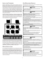
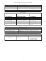
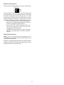
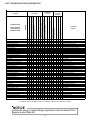
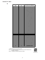
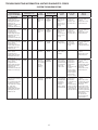
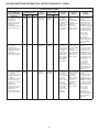
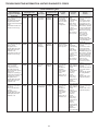
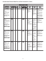
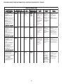
TROUBLESHOOTING INFORMATION: UNITARY DIAGNOSTIC CODES
Digit 3
Digit 2
Digit 1
Run time for last 4 cycles
is less than 3 minutes
each.
Compressor protector has
not tripped.
Low pressure and high
pressure switches are
closed.
Integrated control
module diagnostic/status
LED display shows the
indicated code.
0
3
Short Cycling
Compressor and outdoor
f
.
Compressor protector trips
four consecutive times.
Average run time between
trips is less than 15
seconds.
Integrated control
module diagnostic/status
LED display shows the
indicated code.
0
4
Locked Rotor
CMPR
SHRT
CYCLE
03
Intermittent
thermostat
demand.
Faulty
compressor
relay.
Check thermostat
and thermostat
wiring; repair/
replace as
needed.
Check
compressor
relay operation;
replace control as
needed.
Turn power OFF prior
to repair.
Fault will clear after 4
consecutive normal
cycles.
Fault may be cleared
by cycling 24VAC to
control.
Replace with correct
replacement part(s).
Minimum compressor
runt time is changed
from 30 seconds to 3
minutes.
04
Compressor
bearings are
seized.
Failed
compressor run
capacitor.
Faulty run
capacitor wiring.
Low line voltage.
Check
compressor
operation; repair/
replace as
needed.
Check run
capacitor; replace
as needed.
Check wiring;
repair/replace as
needed.
Verify line voltage
is within range
on rating plate;
contact local
utility is out of
range.
Turn power OFF prior
to repair.
Must clear fault by
cycling 24VAC to
control.
Replace with correct
replacement part(s).
05
Power is
disconnected.
Failed
compressor
protector.
Compressor not
properly wired to
control.
Check circuit
breakers and
fuses.
Check wiring
to unit; repair/
replace as
needed.
Check
compressor;
repair/replace as
needed
Check
compressor
wiring; repair/
replace as
needed.
Turn power OFF prior
to repair.
Fault will clear after 1
normal cycle.
Fault may be cleared
by cycling 24VAC to
control.
Replace with correct
replacement part(s).
06
Compressor start
winding is open.
Failed
compressor run
capacitor.
Faulty run
capacitor wiring.
Compressor not
properly wired to
control.
Faulty
compressor
wiring.
Check
compressor;
repair/replace as
needed.
Check run
capacitor; replace
as needed.
Check wiring;
repair/replace as
needed.
Turn power OFF prior
to repair.
Fault will clear after 1
normal cycle.
Fault may be cleared
by cycling 24VAC to
control.
Replace will correct
replacement part(s).
ROTOR
displays error message.
Compressor and outdoor
f
or greater than
4 hours.
Low pressure and high
pressure switches are
closed.
Integrated control
module diagnostic/status
LED display shows the
indicated code.
0
5
Open Circuit
CIRCUIT
displays error message.
Compressor and outdoor
f
.
Low pressure and high
pressure switches are
closed.
Integrated control
module diagnostic/status
LED display shows the
indicated code.
0
6
Open Start
Circuit
START
displays error message.
21