1
HEWLETT' " PACKARD
OPERATING AND SERVICE MANUAL
86222A/B
RF PLUG-IN
(Including Options 002. 004. <11'111 002/(04)
SERIAL NUMBERS
This manual applies directly to FlP Model 86222A
with serial prefix 1725A and to FlP Model 86222B
with serial prefix 1722A.
With changes described in Section VII, this manual
also applies to FlP Model 86222A prefixes 1516A,
1549A, 1606A, and 1636A; and to HP Model
86222B prefixes 1522A, 1552A, 1601A, 1604A,
and 1628A.
For additional information about serial numbers,
see INSTRUMENTS COVERED BY MANUAL in
Section 1.
COPYRIGHT
© HEWLETT"PACKARD COMPANY 1975, 1977
1400 FOUNTAIN GROVE PARKWAY, SANTA ROSA, CALIFORNIA, 95404 U.s"A"
MANUAL PART NO" 86222"90009
Microfiche Part No. 86222·90010
Printed; OCTOBER 1977
MANUAL CHANGES
r-r-
MANUAL IDENTIFICATIDNModel Number: 86222A/B
Date Printed: October 1977
Part Number: 86222·90009
This supplement contains important information for correcting manual errors and for adapting the manual to
instruments containing improvements made after the printing of the manual.
To use this supplement:
Make all ERRATA corrections
Make all appropriate serial number related changes indicated in the tables below.
86222A
r-r- Serial Prefix or Number -t-r-r- Make Manual Changes_
1725A
L
~i
I
I
862228
Serial Prefix or Number -r-r-r--: Make Manual Changes
l722A
1
] 731A
1,2
1732A
],2
]832A, ]903A
1,2,5
l74lA
1,2,3
]905A
],2,5,7
l8]5A
],2,3,4
2035A
1,2,5,7,8
]832A
],2,3,4,5
] 835A, ] 902A
1,2,3,4,5,6
1905A
1,2,3,4,5,6,7
2035A
],2,3,4,5,6,7,8
.NEWITEM
.'"
Lc;
ERRATA
Title page:
Change first two paragraphs under SERIAL NUMBERS to read: This manual applies directly to lIP Model
86222A with serial prefix] 636A and to lIP Model 86222B with serial prefix l628A,
With changes described in Section VII, this manual alsc applies to HP Model 86222A prefixes ]5l6A, ] 529A,
and l606A; and to lIP Model 86222B prefixes ]522A, ]552A, ]60]A, and ]604A,
!!>'Page ]·0, Figure r.i.
Change the part number of the scale to: 86222·20029.
Page ]-4, Table ]·1:
Change footnote 4 to: Use HP Mode] 432A power meter, sweep duration >]0 seconds.
Page ]·5, Table 1·2, under "Marker Output (power Output +3 to +13 dBm)":
Change "Amplitude Mode: 0.5 dB" to "Amplitude Mode: >0.5 dB (internally adjustable)."
Page] ·6, Table ]·3:
Change U4 (for options 002 and 002/004) to HP Part No. 86222·60055.
NOTE
Manual change supplements are revised as often as necessary to keep manuals as current and accurate as possible.
Hew let.t-Packard recommends that you periodically request the latest edition of this supplement. Free copies are available
from all HP offices. When requesting copies quote the manual identification Information from your supplement, or the model
number and print date f.rom the title page of the manuaL
20 AUGUST 1980
]6 Pages
Printed in U.S.A.
HEWLETT
PACKARD
I
I
I
I
I
I
I
I
I
I
I
I
I
I
I
I
I
I
I
I
I
I
I
I
I
I
I
I
I
I
86222·90009
Model 86222A/B
ERRATA [Cunt'd]
Page 1-8, Table 14:
Change Power Meter and Power Sensor to Power Meter and Thermistor Mount and Model numbers to HP
432A!8478B.
Page 24, Table 2-2:
Change Power Meter and Power Sensor to PowerMeter and Thermistor Mount and Model numbers to HP
432A/8478B.
Page 2-6, Paragraph 2-28:
In Figure 24, change Power Sensorto Thermistor Mount.
In EQUIPMENT list, change Power Meter model number to HP 432A, change Power Sensor to Thermistor
Mount, and model number to HP 8478B.
Page 2-7, Paragraph 2-29:
In EQUIPMENT list, change Power Meter model number to HP 432A, change Power Sensor to Thermistor
Mount, and model number to HP 8478B.
Page 3·7, Figure 3·3 (3 of 3)
Change step 3 to:
Depress LINE pushbutton switch. to turn on mainframe. With mainframe on, LINE . ' and FULL SWEEP!
START MARKER
pushbutton should light.
Change step 6 to:
Set 8620C Markers switch f.l!) to INTEN position and 3 markers should appear on oscilloscope trace as intensified
spots. Adjust oscilloscope intensity for best contrast. Set MARKER switch f.l!) to AMPL position and markers should
appear on oscilloscope trace as a pIp. Set MARKER switch f.l!) to OFF.
0
Page 3·13, FIgure 3·5:
Change callouts to indicate a 10 MHz to 2.4 GHz range.
Page 3·13, Figure 3·6:
Change callout to 0.5 dB.
Page 3·14, Figure 3·8:
In equipment setup, change Power Sensor 10 Thermistor Mount.
In EQUIPMENT list, change Power Meter model number to HP 432A, change Power Sensor to Thermistor
Mount, and model uumber to HP 8478B,
Page 3-15, Figure 3-8:
Change Model Number of BNC·To·Dual Banana Post adapter to read: "HP I01 I OA OR HP 1011OB(2 places).
Page 3-17, Figure 3-9:
In'equipment setup, change Power Sensor to Thermstor Mount.
In EQUIPMENT list, change Power Meter model number to HP 432A, change Power Sensor to Thermistor
Mount, and model number to HP 8478B.
Page 4·2, Paragraph 4-8:
Change Frequency Stability Specification to:
frequency Stability:
With Temperature: <;; ± 500 kHztC.
With 10% Line Voltage Change: <;; ± 20 kHz.
With 3 : 1 Load SWR, All Phases: <;; ± 10kHz.
With 10 dB Power Levei Change: <;; ± 100 kHz.
I
I
I
I
I
I
I
I
I
I
I
I
I
I
I
I
I
I
Model 86222A/B
General Information
862226 RF PLUG·IN
SCALE FOR 8620A/C
86222-90029
~}
~p=J========::1)
RF TEST CABLE
86290-20032
RESISTIVE BARREL
(86222B ONLY)
5061-1015
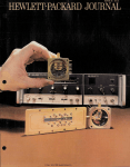
Figure i-i. Modei 86222B RF Plug-In with Accessories Supplied
1-0
I
I
I
I
I
I
I
I
I
I
I
I
I
I
I
I
I
I
I
I
I
I
I
I
I
I
I
I
I
I
I
I
General Information
Model 86222A/B
SECTION I
GENERAL INFORMATION
1-1. INTRODUCTION
1-10.
1-2. This Operating and Service manual contains
information required to install, operate, test, adjust,
and service the Hewlett-Packard Model 86222A/B
RF Plug-in. Fignre 1-1 shows the instrument and
accessories supplied. This section covers instrument
identification, description, options, accessories,
specifications, 'and other basic information.
1-11. BEFORE APPLYING POWER maker sure
the instrument's ac input is set for the available ac
line voltage, that the correct fuse is installed, and
that all normal safety precautions have been taken.
(See Warnings below.)
1-3. Supplied with this manual is an Operating Information Supplement. The Supplement is a copy
of the first three sections of the manual, and
should be kept with the instrument for use by the
operator,
Instruction manual symbol: The apparatus will be marked with this symbol when
it is necessary for the user to refer to the
instruction manual in order to protect the
apparatus against damage.
1-4. Also listed on the title page of this manual is
a Microfiche part number. This number can be
used to order 4 x 6-inch microfiche transparencies
of the manual. Each microfiche contains up to 60
photo-duplicates of the manual pages. The microfiche package also includes the latest Manual
Changes supplement as well as all pertinent Service
Notes.
1-12.
7
..L
I
1-9. This product and related documentation
must be reviewed for familiarization with safety
markings and instructions before operation. This
product has been manufactured and tested in accordance with Hewlett-Packard standards.
Indicates dangerous voltages .
Earth Terminal
I
The WARNING sign denotes a
hazard. It calls attention to a
procedure, practice, or the like,
which, if not correctly performed
or adhered to, could result in injury or loss of life. Do not proceed beyond a WARNING sign
until the indicated conditions are
fully understood and met.
The CAUTION sign denotes a
hazard. It calls attention to an
operating procedure, practice, or
the like which, if not correctly
performed or adhered to, could
result in damage to or destruction of part or all of the equipment. Do not proceed beyond a
CA UTION sign until the indicated conditions are fully understood and met.
1-6. Instrument specifications are listed in Table
1-1. These specifications are the performance standards or limits against which the instrument is
tested. Table 1·2 lists supplemental characteristics.
Supplemental characteristics arc not specifications
but are typical characteristics included as additional information for the user.
1-8. General
Safety Symbols
WARNING
1-5. SPECIFICATIONS
1·7. SAFETY CONSIDERATIONS
Operation
1-13.
Service
1-14. Although this instrument has been manufactured in accordance with international safety
standards, this manual contains information, cautions, and warnings which must be followed to
insure safe operation. Service should be performed
only by qualified service personnel, and the following warnings should be observed.
1-1
Model 86222A/B
General Information
I
WARNINGS
I
[~~~!!?~~
is set to the voltage
Any maintenance or repair of the
opened instrument under voltage should
be avoided as much as possible, but if
necessary, should be carried out only by
skilled persons who are aware of the hazard involved.
Capacitors inside the instrument may
still be charged even if the instrument
has been disconnected from its source of
supply.
Ensure that only fuses with the required
rated current and of the specified type
(normal blow, time delay, etc.) are used
for replacement. The use of repaired
fuses and the short-circuiting of fuseholders must be avoided.
If it is suspected that the protection has
been impaired, the instrument must be
made inoperative and be secured against
any unintended operation.
If the mainframe is to be energized via
an auto-transformer (for voltage reduction) make sure the common terminal
is connected to the earthed pole of the
power source.
BEFORE SWITCHING ON THE MAINFRAME, the protective earth terminals
of the instrument must be connected to
the protective conductor of the mains
power cord. The mains plug shall only
be inserted in a socket outlet provided
with a protective earth contact. The protective action must not be negated by
the use of an extension cord (power
cord) without a protective conductor
(grounding). Grounding one conductor
of a two conductor outlet is not sufficient protection.
Any interruption of the protective
(grounding) conductor (inside or outside the instrument) or disconnecting
the protective earth terminal could
make this instrument dangerous.
BEFORE SWITCHING ON THE MAINFRAME, ensure that mainframe's ac
1-2
input
power source.
(cont'd)
of the ac
BEFORE SWITCHING ON THE MAINFRAME, ensure that the ac line fuse is
of the required current rating and type
(normal-blow, time delay, etc).
1-15.
INSTRUMENTS COVERED BY MANUAL
1-16. Attached to the instrument is a serial number plate (Figure 1-2). The serial number is in two
parts. The first four digits and the letter are the
serial number prefix: the last five digits are the
suffix. The prefix is the same for all identical instruments; it changes only when a change is made
to the instrument. The suffix, however, is assigned
sequentially and is different for each instrument.
The contents of this manual apply to instruments
with the serial number prefix(es) listed under
SERIAL NUMBERS on the title page.
.
SERIAL NUMBER
r
PREFIX
\
SU FFIX
Figure 1-2. Typical Serial Number Plate
1-17. An instrument manufactured after the
printing of this manual may have a serial number
prefix that is not listed on the title page. This
unlisted serial number prefix indicates the instrument is different from those described in this manual. The manual for this newer instrument is accompanied by a yellow Manual Changes supplement. This supplement contains "change information" that explains how to adapt the manual to the
newer instrument.
1-18. In addition to change information, the supplement may contain information for correcting
errors in the manual. To keep this manual as current and accurate as possible, Hewlett-Packard
General Information
Model 86222A/B
recommends that you periodically request the
latest Manual Changes supplement. The supplement for this manual is identified with this manual's print date and part number, both of which
appear on the manual's title page. Complimentary copies of the supplement are available from
Hewlett-Packard.
1-19. For information concerning a serial number prefix that is not listed on the title page or in
the Manual Changes supplement, contact your
nearest Hewlett-Packard office.
1-20.
DESCRIPTION
1-21. The HI' Model 86222A/B is designed as a
plug-in for the Model 8620C mainframe. The mainframe and 86222A/B RF Plug-in make up a solidstate sweep signal source with a frequency range of
10 MHz to 2.4 GHz in one continuous sweep. The
Model 86222B provides intensity or amplitude
crystal markers at 1, 10, or 50 MHz intervals. Intensity markers are compatible with most CRT display units, including the HI' Model 8755A Frequency Response Test Set and HI' Model 8410B
Network Analyzer. Front panel connector
MARKER EXT INPUT provides the capability of
generating markers using an external source.
1-22. The RF output of the instruments is controlled by the front panel POWER LEVEL control.
Power can be leveled, externally or internally,
across the band using a conventional power sampling and feedback technique. The automatic level
control (ALC) switch selects the mode of leveling
either internal (INT), external (EXT), or power
meter (MTR). A front panel ALC EXT INPUT connector and ALC GAIN control are provided to use
with an external leveling loop. When the UNLEVELED light is on, it indicates that the leveling
loop is open over a portion of the swept band.
BNC connectors on the rear panel allow for external FM signal inputs and a IV IGHz FREQ REF
output.
1-23.
OPTIONS
lation information is provided in Appendix A. See
Table 1-3 for parts required to install Option 002.
1-27.
Option 004
1-28. The 86222A/B Option 004 moves the RF
OUTPUT connector from the front panel to the
rear panel. Installation information is provided in
Appendix B. Installation of the Option 004 requires the parts listed in Table 1-3.
Option 002/004
1-29.
1-30. The 86222A/B Option 002/004 provides a
rear panel RF OUTPUT connector with a zero to
70 dB step attenuator in the RF signal line. Installation information is provided in Appendix C. Installation of the Option 002/004 requires the parts
listed in Table 1-3.
1-31.
ACCESSORIES SUPPLIED
1-32. Figure I-I shows the HI' Model 86222A/B
RF Plug-in, the dial scale (HI' Part No. 8622220029) to be mounted in the 8620AIC mainframe,
the RF Test cable (HI' Part No. 86290-20032 for
testing and troubleshooting the RF section, and
a Resistive Barrel (HI' Part No. 5061-1015) for
simultaneous RF BLANKING and 86222B Intensity Marker operation (supplied with 86222B
only).
1-33.
EQUIPMENT REQUIRED BUT NOT
SUPPLIED
1-34. To have a complete operating sweep oscillator unit, the Model 86222A/B RF Plug-in must
be installed in an HI' Model 8620C mainframe. HI'
Model 8620A mainframes with serial prefixes
1332A and below require a modification for HI'
Model 8410B Network Analyzer compatibility
over multi-octave sweeps.
NOTE
All 86222A/B operation and maintenance procedures in this manual are set
up using the HI' Model 8620C mainframe. The procedures also apply to the
8620A mainframe, but the controls are
different.
1-24. Options for the Model 86222A/B RF Plugin are available to (1) include a 70-dB built-in attenuator, (2) route the RF OUTPUT connector to
the rear panel, (3) combine the 70 dB built-in attenuator and rear panel RF OUTPUT connector.
1-35.
1-25. Option 002
1-26. Option 002 provides a front panel zero to
70 dB step attenuator in the RF signal line. Instal-
1-36. Service Accessories
1-37. Service Accessories for the 86222A/B RF
Plug-in are available for convenience in aligning and
EQUIPMENT AVAILABLE
1-3
Model 86222A/B
General Information
Table 1·1. Specifications for 86222A/B in 8620C
SPECIFICATiONS
Residual AM (100 kHz Bandwidth): ;;'50 dB below
maximum power.
FREfiUENCY'
Frequency Range:
Calibrated: 10 MHz to 2.4 GHz.
Equivalent Source SWR:
SWR: ,;;; 1.5:1.
Impedance: 50 ohms nominal.
Frequency Accuracy (25'C):'
CWMode: 3 ,;;; ± 10 MHz.
All Sweep Modes (Sweep Time> 0.1 See):
~±
15 MHz.
MODULATION'
Frequency Stability:
With Temperature: ~ ± 500 kHzt C.
With 10% Line Voltage Change: ,;;; ± 20 kHz.
Witb 3: 1 Load SWR, All Phases: ,;;; ± 10 kHz.
With 10 dB Power Level Change: ,;;; ± 100 kHz.
External FM:
Maximum Deviations for Modulation Frequencies:
DC to 100 Hz: ± 75 MIIz.
100 Hz to 1 MIIz: ± 5 MIIz.
1 MIIz to 2 MIIz: ± 2 MHz.
Residual FM in 10kHz Bandwidth (FM·NORM.PL
Switch in NORM position):
CW Mode: ,;;; 5 kHz peak.
External AM:" 5
ON/OFF Ratio: ;;, 30 dB.
Symmetry: 40/60 at > + 10 dBm output power.
Attenuation for +6 volt input: ;;, 30 dB.
POWE R 0 UTPUT'
Power Level (For calibrated frequency range at 25'C):
Maximum Leveled Power:';;' +13 dBm (20 mW).
Power Level Accuracy (Internally Leveled):
,;;; ± 1 dB (Includes Flatness)
Power Variation:
Internally Leveled: 2 ,;;; ± 0.25 dB.
Externally Leveled: 7
Crystal Detector: ,;;; ± 0.1 dB.
Power Meter: 4 ,~± 0.1 dB.
Option 002: ,;;; 0.33 dB ± 0.016 dB/IO dB.
MARKERS (86222B Only)" z
0
6
Marker Generator Accuracy (at 25'C with Power Gutput +3 to +13 dBm):
Center Frequency Accuracy: ± 5 x 10'6
Spurious Signals (below fundamental at specified
maximum leveled power, 25'C):'
Harmonics: > 25 dB.
Non-Harmonics:
0.01'-2.3 GHz: ;;, 30 dB.
2.3'-2.4 GHz: ;;, 25 dB.
1
Internal AM (At Maximum Leveled Power):
1 kIlz Square-wave ON/OFF Ratio: ;;, 30 dB.
RF Blanking ON/OFF Ratio: ;;, 30 dB.
Marker Frequency Range (Power Output +3 to
+13 dBm):
50 and 10 MHz Markers: 10 MIIz to 2.4 GIIz.
1 MHz Marker: 10 MHz to 1 GHz.
o
Unless otherwise noted, all specifications are at 0 to 55 C with plug-in installed in an 8620C mainframe.
2 See also the Supplernental Characteristics, Table 1·2.
3 Approach desired frequency from Iow-Irequenov end of band.
4 Use lIP Model 435A power meter. Sweep duration> 10 seconds.
5Specific requirements for compatibility with HP 8755A.
to external AM input.
± 6V. 27.8 kHz square wave MODULATOR DRIVE output connected
686222B markers will not operate when sweeping from a high frequency to a low frequency.
7 Excludes coupler and detector variation.
1·4
General Information
Model 86222A/B
Table 1-2. Supplemental Characteristics for 86222A/B Installed in 8620C
SUPPLEMENTAL CHARACTERISTICS
NOTE: Values in this table are not specifications but are typical characteristics included for user
information.
FREllUENCY
Frequency Accuracy in Remote Programmed Mode:
Typically ±6 MHz.
linearity:
Correlation between frequency and SWEEP 0 UT
voltage: ± 2 MHz.
Frequency Orilt:
Drift ± 100 kHz per ten minutes after one hour
warm-up.
Frequency Reference Output:
1 Volt/GHz i 0.01 V.
MARKERS (86222B Only)
External Marker Frequency Range:
(Power Output +3 to +13 dBm)
-10 to 0 dBm External Input Power: 10 MHz to
1.0 GHz.
-10 to +10 dBm External Input Power: 1.0 to
2.4 GHz (over limited power range).
Marker Width (around center frequency with Power
Output +3 to +13 dBm):
50 MHz Marker: ±300 kHz
10 MHz Marker: ,200 kHz
1 MHz Marker: ±75 kHz
External Marker: ±300 kHz
POWER OUTPUT
Maximum leveled Power:
Typically < +15 dBm.
Power Variation (Across any 50 MHz portion between
30 MHz and 2.3 GHz):
Typically ±O.05 dR
Stability with Temperature Change:
Typically ±0.02 dB(C.
Temperature Stability (Power Output +3 to +13 dBm):
50 MHz Marker: ~100 Hz!"C.
10 MHz Marker: ±20 Hzt C.
1 MHz Marker: ±2 Hz(C.
Marker Output (Power Output +3 to +13 dBm):
-n- Mode: +3 Volts.
L J Mode: --3 to v-S Volts.
Amplitude Mode: 0.5 dB.
Spurious Signals (dB below fundamental):
Harmonics: Typically ;;>30 dB at +10 dBm.
Non-Harmonics:
10 MHz to 2.3 GHz at +10 dBm:
Typically > 40 dB.
2.3 to 2.4 GHz at +10 dBm:
Typically ;··35 dB.
Broadband Noise (100 kHz Bandwidth):
Noise Level: -c:; -",,70 dBm.
GENERAL
Crystal Input:
Approximately -10 to -100 mV for specified leveling at maximum rated output; for use with negative polarity detectors such as HP Model 780series Directional Detectors, and HP Model 423A
Crystal Detector.
Net Weight: 2.5 kg(5.5 pounds).
MOOUlATION
Shipping Weight: 4 kg (9 pounds).
Sensitivity:
FM Mode (FM-NORM-PL switch in FM position):
Typically -20 MHz/Volt.
Phase-Lock Mode (FM-NORM-PL switch in PL
position): Typically --6 MHz/Volt
Dimensions: Height 12.7 em (5 inches):Width: 14.7 em
(5-13/16 inches); Depth 30.5 em (12 inches).
External AM:
Frequency Response:
Typically 150 kHz.
Options:
Option 002: Zero to 70 dB attenuator.
Option Q04: Rear Panel RF OUTPUT.
1-5
General Information
Model 86222A/B
Table 1 -3 Parts Required for 86222A/B Options
Option
002
Reference
Designator
Al (86222A only)
Al (86222B only)
(86222A only)
(86222B only)
W8
W13
86222-60029
86222·60020
86222-00015
86222-00013
86222·20026
08558-60003
0370-1103
86222·20021
86222-20022
W8
86222-20019
U4
004
HP Part No.
Description
Front Panel Board Assembly
Front Panel Board Assembly
Panel: Front Upper
Panel: Front Upper
Attenuator Bushing
70 dB Step Attenuator
Knob, Pointer
RF Cable: Directional Detector to Attenuator
RF Cable: Attenuator to RF OUTPUT
RF Cable: Directional Detector to Rear Panel
RFOUTPUT
0021004
Al (86222A only)
Al (86222B only)
(86222A only)
(86222B only)
U4
W8
W13
86222-60029
86222·60020
86222·00015
86222-00013
86222·20026
08558-60003
0370·1103
86222-20021
86222·20023
troubleshooting the mainframe and RF Plug-in.
The service accessories kit contains a plug-in extender cahle, extender hoards, adjustment tool, and
RF'.service cables (see Figure 1-3). The service
accessories kit may be obtained from HewlettPackard by ordering Service Accessories Part No.
08620-60030.
1-38. Model 8755A/182C Swept Amplitude
Analyzer and Oscilloscope
1-39. The Model 8620C/86222A/B Sweeper is
compatible with the Hewlett-Packard Model
8755A Swept Amplitude Analyzer. For all swept
amplitude measurements, the 27.8 kHz squarewave modulation is applied directly the the 8620C
rear-panel EXT AM connector. This eliminates the
need for an external modulator, thus providing
maximum available power to a test setup. Section
HI contains techniques and instructions for using
the 8755A for testing and measuring microwave
devices.
Front Panel Board Assembly
Front Panel Board Assembly
Panel: Front Upper
Panel: Front Upper
Attenuator Bushing
70 dB Step Attenuator
Knob, Pointer
RF Cable: Directional Detector to Attenuator
RF Cable: Attenuator to Rear Panel RF OUTPUT
also available using an HP 423A Crystal Detector.
Section III contains detailed instructions for using
the external power leveling systems.
1-42. Model 841 OB/8411 A Network Analyzer
1-43. The Model 8620C/86222A/B Sweeper provides multi-octave phase/gain measurement capability with the Hewlett-Packard Model 8410B Network Analyzer System. The combination of the
Model 8410B Network Analyzer, the Model 8411A
Frequency Converter, and an appropriate display
plug-in forms a phasemeter and a ratiometer for
direct phase and amplitude ratio measurement of
RF voltages. These measurements can be made on
single frequencies and on swept frequencies from
110 MHz to 2.4 GHz. The interfacing between the
8410B and the 8620C/86222A/B sweeper permits
the 8410B to phase lock over the 110 MHz to
2.4 GHz range.
1-44. RECOMMENDED TEST EQUIPMENT
1-40. Power Meters and Crystal Detectors
1-41. The Hewlett-Packard Model 435A Power
Meter may be used for external leveling of the
Model 86222A/B Plug-in. External leveled power is
1-6
1-45. Equipment required to maintain the Model
86222A/B is listed in Table 1-4. Other equipment
may be substituted if it meets or exceeds the critical specifications listed in the table.
General Information
Model 86222A/B
Item
Name
Part No.
Use
08620-60032
Moves RF Plug-in outside mainframe for alignment
or service
1
Extender Cable
2
RF Service Cable
(2 each)
8120-1578
Allows troubleshooting RF circuits
3
Adjustment Tool
8830-0024
Fits miniature adjustment slot on potentiometers
4
RF Connector, straight
adapter. SMA jack to
SMA jack (2 each)
1250·1158
Adapts RF Service cables from plug to jack
5
Service Board
6
18 Pin Extender Board
08620-60037
5060·2041
Allows probing RF Section interface or programming connector during performance test or
troubleshooting
Extends mainframe boards for troubleshooting
Figure 1-3. Service Accessories Kit, HP Part No. 08620-600:JO
1-7
Model 86222AjB
General Information
Table 1-4. Recommended Test Equipment (1 of 2)
Instrument
Critical Specifications
Recommended
Model
Use*
Sweep Oscillator
8620A is only substitution.
HP 8620C
P,A,T
Spectrum Analyzer
Frequency Range: 10 MHz to 2.4 GHz
HP 8555A/8552BI
141T
P
Oscilloscope with DualTrace Vertical Amplifier
and 10: 1 probes
Vertical Amplifier: Dual Trace with 10: 1 probes.
Bandwidth: 20 MHz minimum
Vertical Sensitivity: 5 mV IDiv
Horizontal Sweep Rate: 1 /ls!Div minimum
HP 182C/1801A!
1820C
P,A,T
DC Digital Voltmeter
Range: -50V to +50V
Accuracy: ±0.006%
Input Impedance: 10 megohms minimum
HP 3490A
P,A,T
Power Splitter
Frequency: 10 MHz to 2.4 GHz
Attenuation in each arm: 6 dB
HP 11667A
P
Service Boards**
(See Figure 1-3)
HP 08620-60037
T
Extender Cable**
(See Figure 1-3)
HP 08620·60032
T
Adjustment 1'001**
(See Figure 1.3)
HP 8830-0024
A
Crystal Detector
Frequency: 10 MHz to 2.4 GHz
SWR: <1.2 to 2.4 GHz
Polarity: Negative
HP 423A
P, A
Power Meter and Power
Sensor
Frequency: 10 MHz to 2.4 GHz
Range: +10 dBm to -20 dBm
HP 435A/8482A
Pl A
3 dB Attenuator
Attenuation: 3 dB ± 0.3 dB
Frequency: Dc to 2.4 GHz
HP 8491A, Opt. 003
P
10 dB Attenuator
Attenuation: 10 dB ±0.5 dB
Frequency: Dc to 2.4 GHz
HP 8491A, Opt. 010
P,A,T
20 dB Attenuator
Attenuation: 20 dB ±0.5 dB
Frequency: Dc to 2.4 GHz
HP 8491A, Opt. 020
BNC Tee
Connectors: 1 male and 2 female
HP 1250-0781
P,A,T
Swept Amplitude Analyzer and Oscilloscope
Mainframe
Frequency Range: 15 MHz to 2.4 GHz
HP 8755A/182T
A
Detectors
Frequency Response: 15 MHz to 2.4 GHz
Error: <1.3 dB
Impedance: 50 ohms
HP 11664
A
* P = Performance Test; A "" Adjustments; T '" Troubleshooting
** These parts are included in Service Accessories Kit No. 08620-60030
1-8
Model 86222A/B
General Information
Table 1·4. Recommended Test Equipment (2 of 2)
Instrument
**
Critical Specifications
Recommended
Model
Use'
Impedance: 50 ohms
Connectors: SMA to SMA (Figure 1-3)
HP 8120·1578
T
RF Connector Adapter**
SMA jack 'to SMA jack (Figure 1-3)
HP 1250-1158
T
18~Pin
(See Figure 1·3)
HP 5060-2041
T,A
Function Generator
Frequency: 10 Hz to 2.1 MHz
Output: 12V peak-to-peak square-wave
HP 3310A
P,A
RMS Voltmeter
Scale: RMS volts
Range: 0 to -70 dB
Accuracy: ±5%
Frequency Range: 10 Hz to 100 kHz
HP 3400A
P
DC Power Supply
Range: 0 to 10 Vdc
Current: 0.1 Amp
HP 6213A
P
Adjustable AC Line
Transformer
Output: 100 to 150 Vac
Power: 150 watts
General Radio MT32
P
Directional Coupler
Coupling: 20 dB
Directivity: >25 dB
SWR all ports: <1. 3
HP 778D
P, T
Frequency Counter
Range: 1 MHz to 2.4 GHz
HP 5340A
P,A,T
Cable
2·ft long,'BNC connectors
HP 11086A
P
50 Ohm Load
Impedance: 50 Ohms
ENe, Male Connector
HP 11593A
A
Adjustable Short
Type N, Male connector
Microlab FXR
50·6 MN
P
RF Service Cable
*
**
Extender Board**
P '" Performance Test; A "" Adjustments;
'r "" Troubleshooting
These parts arc included in Service Accessories Kit No. 08620-60030.
1-9/1·10
Installation
Model 86222AjB
SECTION II
INSTALLATION AND INCOMING INSPECTION TESTS
2-1. INSTALLATION
2-2. This section provides installation instructions
for Model 86222AjB RF Plug-in and its accessories.
It also includes information about initial inspection
and damage claims, preparation for using the RF
Plug-in and packaging, storage and shipment, and
incoming inspection.
2-3. INITIAL INSPECTION
2-4. Inspect the shipping container for damage. If
the shipping container or cushioning material is
damaged, it should be kept until the contents of
the shipment have been checked for completeness
and the instrument has been checked mechanically
and electrically. The contents of the shipment
should be as shown in Figure 1-1, and procedures
for checking electrical operation are given in Section IV. If the contents are incomplete, if there is
mechanical damage or defect, or if the RF Plug-in
does not pass the performance tests, notify the
nearest Hewlett-Packard office. If the shipping container is damaged, or the cushioning material shows
signs of stress, notify the carrier as well as the
Hewlett-Packard office. Keep the shipping materials for carrier's inspection. The HP office will
arrange for repair or replacement without waiting
for claim settlement.
2-5. PREPARATION FOR USE
2-6. Power Requirements
2-7. When the Model 86222AjB RF Plug-in is
properly installed, it obtains all power through the
rear interface connector from the HP Model
8620AjC Sweep Oscillator mainframe.
2-8. Interconnections
2-9. For the Model 86222A/B RF Plug-in to operate, it must be plugged into an 8620A or 8620C
mainframe. Connection is made by pushing the RF
Plug-in into the mainframe so that the plug-in
interface connector PI mates with the mainframe
connector.
2-10. Mating Connectors
2-11. The mating connectors for the HP Model
86222A/B RF Plug-in are shown in Table 2-1. This
table identifies the mating connector for each front
and rear panel connector on the RF Plug-in and gives
theHPPartNo.and part numbers of alternate sources.
2-12. Operating Environment
2-13. Temperature. The instrument may be oper0
ated in temperatures from 00 C to +55 C.
2·14. Humidity. The instrument may be operated
in environments with relative humidity up to 95%.
However, the instrument should also be protected
from temperature extremes which cause condensation within the instrument.
2-15. Altitude. The instrument may be operated at
altitudes up to 4572 meters (15,000 feet).
2-16. Frequency Scale Installation
2-17.
NOTE
If R F Plug-in is installed in mainframe,
it must be removed to install frequency
scale. See R F Plug-in removal instructions in Paragraph 2-20.
To install frequency scale, proceed as follows:
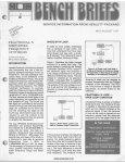
a. Disengage mainframe front-panel latch
handle, shown in Figure 2-1, by pushing downward
on handle while pushing inward lightly on top of
front paneL
b. Swing front panel forward and down to
position shown in Figure 2-2.
c. Depress mainframe front-panel BAND select lever, shown in Figure 2-1, to rotate frequency
scale drum until desired scale position is accessible.
NOTE
The frequency scale for the 86222A/B
RF Plug-in may be installed in any frequency scale drum position. If necessary
to remove a frequency scale, exert a
pressure OUTWARD, away from drum,
on right-hand edge of scale.
d. Insert frequency scale so key (a 1j16-inch
long, 1/2 inch wide protrusion) on left end of scale
2-1
Model 86222A/B
Installation
Table 2-1. Model 86222A/B Mating Connectors
Connector
on
Instrument
J1 MARKER EXT INPUT (86222B only)
Mating Connector
Industry Identification
Type ENe, male connector
UG-88IU
Alternate Sources
HP Part No.
1250-0256
AmphenoI31-202-1021
Bendix 12638-3
J2 MARKER OUTPUT
(86222B only)
Specialty Connector 28P118-1
J4 ALC EXT INPUT
J5 FM
J6 FREQ REF
J3 RF OUTPUT
Type N, male connector
UG-21GIU
1250-0882
Bendix 30481-2
Specialty Connector 25P117-2
J3 Rear RF OUT
(Option 0021004)
DETAIL VIEW OF MAINFRAME
FRONT-PANEL LATCH
HANDLE
(SHOWN IN LOCKED POSITION)
FRONT-PANEL LATCH HANDLE
(SHOWN IN DISENGAGED POSITION)
BAND
SELECT
LEVER
Figure 2-1. Installation of Frequency Scale and lIF Plug-in
2-2
Installation
Model 86222AjB
fits into notch in roller on left-hand edge of drum
(see Figure 2-2).
e.
To prevent damage to frequency pointers
when bandswitch drum is rotated, make
certain that frequency scale is firmly in
place and flush with band drum edges.
Push inward on right-hand edge of frequency scale to snap it into place on frequency
scale drum.
f. Return front panel to upright (closed)
position, and, while pushing inward lightly on top
of front panel, re-engage front-panel latch handle
by pushing it upward to lock positions as shown in
Figure 2-1, inset view.
b. Position latch handle located on left side
of RF Plug-in so it is perpendicular to front panel.
Portion of handle with rectangular cut-out should
be facing forward and portion with notch should
be facing rear of RF Plug-in.
c. Slide RF Plug-in into mainframe towards
rear of compartment. RF Plug-in latch handle will
engage a locking pin, shown in Figure 2-1, inside
mainframe and exposed portion of latch handle
will start to move downward.
d. Push latch handle downward, while still
pushing inward on RF Plug-in, until latch handle is
flush with front panel.
2-20. Removal. To remove RF Plug-in, proceed as
follows:
a. Push inward on top of latch handle and
pull forward and up on bottom of latch handle.
2-18. RF Plug-in Installation and Removal
2-19. Installation. To install RF Plug-in proceed as
follows:
a. If mainframe power is ON, press mainframe LINE switch to OFF position.
BAND INDICATOR
NOTCH
b. When exposed portion of latch handle is
in a position perpendicular to RF Plug-in front
panel, it is disengaged from locking pin (Figure
2-1) and RF Plug-in may be removed by pulling
forward on latch handle.
FREOUENCYSCAlEORUM
DEPRESSION
Figure 2··2. Mainframe Front Panel in Open Position
2-:3
Installation
Model 86222AjB
2-21. Installation of Options
2-22. To install or remove options, refer to the installation instructions in the appendixes for the
applicable options.
prefixes 1332A and below, order the 8620A
Mainframe Modification Kit, HP Part Number
08620-60099. Service Note 8620A-6A explains the
modifcation,
2-25. INCOMING INSPECTION TESTS
2-23. MODIFICATIONS
2-24. Unmodified 8620A mainframes, which include prefixes 1332A and below, will not operate
for continuous multi-octave frequency measurements with the HP Model 8410B Network Analyzer. To modify 8620A mainframes with serial
2-26. The following procedures test selected specifications to determine that the instrument is functioning properly for the requirements of incoming
inspection. The recommended test equipment is
listed in Table 2-2. Equipment that meets or exceeds the critical specifications may be substituted.
Table 2-2. Recommended Test Equipment for Incoming Inspection Tests
Instrument
Critical Specifications
Recommended
Model
Sweep Oscillator
8620A Is only substitution.
HP 8620C
Oscilloscope with DualTrace Vertical Ampli-
Vertical AmplIfier: Dual trace with 10:1 probes
Bandwidth: 20 MHz minimum
HP 182C/1801Aj1820C
fier and 10: 1 probes
Vertical Sensitivity: 5 mV IDiv
Horizontal Sweep Rate: 1 j1sjDiv minimum
Frequency Counter
Range: 1 MHz to 2.4 GHz
HP 5340A
Power Meter and
Power Sensor
Frequency: 10 MHz to 2.4 GHz
Range: +10 dBm to -20 dBm
HP 435A/8482A
Crystal Detector
Frequency: 10 MHz to 2.4 GHz
SWR: <1.2 to 2.4 GHz
Polarity: Negative
HP 423A
Power SplItter
Frequency: 10 MHz to 2.4 GHz
HP 11667A
Attenuation in each arm: 6 dB
10 dB Attenuator
Attenuation: 1.0 dB ± 0.5 dB
Frequency: De to 2.4 GHz
HP 8491A, Option 01.0
3 dB Attenuator
Attenuation: 3 dB to.3 dB
HP 8491A, Option 003
Frequency: Dc to 2.4 GHz
2-27. Frequency Range and Accuracy
SPECIFICATION:
Frequency range: 10 MHz to 2.4 GHz
Frequency accuracy (at 25'C ambient):
±10 MHz CW mode. (Approach desired CW frequency from low-frequency end of
band.)
±15 MHz All Sweep Modes (Sweep Time >0.1 sec.)
DESCRIPTION:
The CW mode is checked at three frequencies across the band to determine if the RF
signal is within frequency tolerance. Start-stop sweep is then selected and the frequency
at each end-point is checked.
2-4
Installation
Model 86222A/B
INCOMING INSPECTION TESTS
2-27. Frequency Range and Accuracy (Cont'd]
SWEEP
OSCILLATOR
RF
PLUG·IN
FREQUENCY COUNTER
INI"UT
10dB
ATTENUATOR
Figure 2-3. Frequency Range and Accuracy Test Setup
EQUIPMENT:
SW<1ep Oscillator. .
RF Plug-in . . . .
Frequency Counter .
10 dB Attenuator
PROCEDURE:
a.
Connect equipment as shown in Figure 2-3. Connect frequency counter through a
10 dB attenuator to the 86222A/B RF OUTPUT connector. Press 8620C LINE
switch to the ON position.
b.
Set controls as follows:
8620C
START MARKER Pointer
STOP MARKER Pointer .
MODE
.
1 kHz SQ WV-OFF (Rear panel)
86222A/B
RF . . .
POWER LEVEL
ALC Switch
FM-NORM-PL .
HP
HP
HP
HP
8620C
86222A/B
5340A
8491A, Option 010
0.02 GHz
2.4 GHz
MANUAL
OFF
ON
+13 dBm
INT
NORM
c.
Allow equipment to warm up for 30 minutes. Press 8620C CW pushbuttons. Set
frequency counter to measure frequencies from .01 GHz to 2.4 GHz.
d.
Set CW pointer to .01 GHz. Frequency counter should indicate 10 MHz ±10 MHz.
e.
Set CW pointer to 1.2 GHz. Frequency counter should indicate 1.2 GHz ±.01 GHz.
f.
Set CW pointer to 2.4 GHz. Frequency counter should indicate 2.4 GHz ± .01 GHz.
g.
Press FULL SWEEP pushbutton. Set MANUAL control fully counterclockwise. Frequency counter should indicate 20 MHz ± 15 MHz.
h.
Set MANU AL control fully clockwise. Frequency counter should indicate 2.4 GHz
± .015 GHz.
2-5
Model 86222A/B
Installation
INCOMING INSPECTION TESTS
2-28.
Power Level and Variation Test
SPECIFICATION: Maximum Leveled Power (25"C):;;;' +13 dBm.
Power Variation (at maximum leveled power): Internally Leveled: ±0.25 dB.
DESCRIPTION:
Maximum leveled power is measured by a power meter. Power level variations with internalleveling are eheeked. The power variations are measured with a power meter.
SWEEP
OSCILLATOR
nii--- - . .
1_::.".__-,="
POWER
METER
RF
PLUG IN
--i1
H
~-~
,00111
RF
INPUT
OUTPUT
10 dB
ATTENUATOR
POWER
SENSOR
T
Figure 2-4. Internal Leveling Test Setup
EQUIPMENT:
Sweep Oscillator
RF Plug-in .
Power Meter
Power Sensor
10-dB Attenuator
PROCEDURE:
a.
HP
HP
HP
HP
HP
8620C
86222A/B
435A
8482A
849lA, Option 010
Allow 30 minutes warm-up time. Set controls as follows:
8620C
2-6
START MARKER Pointer
STOP MARKER Pointer.
CW Pointer
.
MODE
.
RF BLANKING-OFF (Rear panel).
10 MHz
2.4 GHz
1.2 GHz
MANUAL
RF BLANKING
86222A/B
RF .
ALC
ON
INT
b.
Connect equipment as shown in Figure 2-4.
c.
Set 86222A/B POWER LEVEL to maximum leveled power (UN LEVELED light
out).
d.
Manually tune 8620C from full CCW to full CW, slowly enough for power meter
to respond. Note maximum and minimum power readings.
Model 86222A/B
Installation
INCOMING INSPECTION TESTS
2-28.
Power Level and Variation Test (Cont'd)
e.
2-29.
Difference between maximum and minimum power readings should be ";;0.5 dBm.
Minimum reading should not be lower than +3 dBm.
Internal Amplitude Modulation Test
SPECIFICATION:
All tests are referenced to the 86222A/B RF OUTPUT power set to the specified maximum power of +13 dBm.
Internal AM: RF Blanking (selected by 8620C RF BLANKING-OFF switch) ON/OFF
ratio> 30 dB.
DESCRIPTION:
Internal AM is checked for RF blanking on/off ratio. The on/off ratio is determined by
power level measurement in the RF BLANKING and OFF conditions.
SPECTRUM ANALYZER
RF
OUTPUT
Figure 2-5. Internal Amplitude Modulation Test Setup
EQUIPMENT:
Sweep Oscillator
RF Plug-in .
Power Meter
Power Sensor
Spectrum Analyzer
PROCEDURE:
a.
Connect equipment as shown in Figure 2-5. Allow 30 minutes warm-up time.
b.
Set controls as follows:
Sweep Oscillator:
START MARKER Pointer . . . .
MARKER SWEEP Pushbutton
RF BLANKING-OFF (Rear Panel)
MODE . .
TRIGGER
.
1.2 GHz
Depressed (On)
OFF
AUTO
EXT
RF Plug-in:
RF . . .
ALC
FM-NORM-PL .
ON
INT
NORM
Spectrum Analyzer:
BANDWIDTH
.
SCAN WIDTH
.
2 dB LOG-I0 dB LOG-LINEAR
10 kHz
20 MHz/DIV
10 dB LOG
HP 8620C
HP 86222A/B
HP 435A
HP 8482A
HP 8555A/8552B/141T
2-7
Installation
Model 86222A/B
INCOMING INSPECTION TESTS
2-29.
Internal Amplitude Modulation Test (cont'd)
c.
Adjust 86222A/B POWER LEVEL for maximum leveled power.
d.
Adjust spectrum analyzer to center RF carrier on display.
e.
Set LOG REF LEVEL on spectrum analyzer to top graticule line.
f.
Set 8620C RF BLANKING-OFF switch to RF BLANKING and note the difference
in power level (ON/OFF ratio). The ON/OFF ratio should he greater than 30 dB.
2-30. Marker Range Test (862228 Only)
SPECIFICATION:
Marker Frequency Range:
10 and 50 MHz Markers: 10 MHz to 2.4 GHz
1 MHz Marker: 10 MHz to 1 GHz.
DESCRIPTION:
Marker frequency range is determined by using an oscilloscope and crystal detector to
display the markers.
_-----i
SWEEP
OSCILLATOR
,--- -
t9)
~
RF
PLUG-IN
MARKER
OUTPUT
Z-AXIS INPUT
H-------------------...
-:l
,l
SWEEP
OUT
OSCILLOSCOPE
W
HQRIZ
INPUT
RF
OUTPUT
VERT
INPur
10 dB
ATTENUATOR
CRYSTAL
OE"fECTOR
Figure 2-6. Marker Range Test Setup
EQUIPMENT:
Sweep Oscillator
RF Plug-in . .
Oscilloscope
Crystal Detector
10-dB Attenuator
PROCEDURE:
a.
Connect equipment as shown in Figure 2-6. Set 8620C LINE switch to ON and
allow 30 minutes warm-up time.
b.
Set controls as follows:
2-8
HP
HP
HP
HP
HP
8620C
86222B
182C/1802A/1820C
423A
8491A, Option 010
Model 86222AjB
Installation
INCOMING INSPECTION TESTS
2-30. Marker Range Test (86222B Only) (cont'd)
8620C
CW Pointer
LiF Pointer
MODE . .
TRIGGER
TIME-SECONDS Switch
TIME-SECONDS Vernier.
RF BLANKING-OFF
86222B:
RF
....
POWER LEVEL
ALC . . . .
MARKER FREQ MHz
MARKER MODE
FM-NORM-PL. . . .
c.
100 MHz
160 MHz
AUTO
INT
1 to .01
Fully Clockwise
RF BLANKING
ON
+13 dBm
INT
50
J"L
NORM
NOTE
The oscilloscope display consists of the selected Li F pointer frequency
swept symmetrically around the selected CW point of frequency. For
example, with the CW pointer at 100 MHz and a LiF of 100 MHz, the
display is from 50 MHz to 150 MHz. To determine the frequency
range of the markers, the first and last good markers should each be
centered on the oscilloscope display, and either the CW pointer frequency setting read directly, or the 8620C put in CW mode and the
output frequency read with a frequency counter.
Press 8620C LiF pushbutton and adjust LiF to display from 2 to 8 markers on oscilloscope display. Adjust oscilloscope intensity for best marker contrast.
d.
Slowly adjust 8620C CW control to display from 10 MHz to 2.4 GHz and ensure
50 MHz markers are present and stable over the full calibrated frequency range.
e.
Set MARKER FREQ MHz switch to 10 and adjust LiF to display between 2 and 8
markers on oscilloscope display.
f.
Slowly adjust 8620C CW control to display from 10 MHz to 2.4 GHz and ensure
10 MHz markers are present and stable over the full calibrated frequency range.
g.
Set MARKER FREQ MHz switch to 1 and adjust Li F to display between 2 and 8
markers on oscilloscope display.
h.
Slowly adjust 8620C CW control to display from 10 MHz to 1 GHz and ensure 1 MHz
markers are present and stable up to 1 GHz.
2-9
Model 86222AjB
Installation
2-31.
STORAGE AND SHIPMENT
2-32. Environment
2-33. The instrument may be stored or shipped in
environments within the following limits:
2-36. Other Packaging. The following general instructions should be used for re-packaging with
commercially available materials:
a.
Wrap instrument in heavy paper or plastic.
(If shipping to Hewlett-Packard office or service
Temperature
Humidity
Altitude
'"
--40'C to +75'C
Up to 95% relative
15240 meters (50,000 feet)
center, attach tag indicating type of service required, return address, model number, and full
serial number.)
The instrument should also be protected from
temperature extremes which cause condensation
within the instrument.
b. Use strong shipping container. A doublewall carton made of 350-pound test material is
adequate.
2-34. Packaging
2-35. Original Packaging. Containers and materials
identical to those used in factory packaging are
available through Hewlett-Packard offices. If the
instrument is being returned to Hewlett-Packard
for servicing, attach a tag indicating the type of service required, return address, model number, and
full serial number. Also, mark the container FRAGILE to assure careful handling. In any correspondence, refer to the instrument by model number
and full serial number.
2-10
c. Use enough shock-absorbing material (3
to 4-inch layer) around all sides of instrument to
provide firm cushion and prevent movement inside
container. Protect control panel with cardboard.
d.
Seal sbipping container securely.
e. Mark sbipping container FRAGILE to
assure careful handling.
f. In any correspondence, refer to instrument by model number and full serial number.
Operation
Model 86222AjB
SECTION III
OPERATION
3-1_
INTRODUCTION
3-2. This operating section explains the function
of the controls and indicators of the Model
8G222AjB RF Plug-in. It describes typical operating modes in a measurement system.
3-3. PANEL FEATURES
3-4. Front and rear panel features are described
in Figures 3-1 and 3-2. Description numbers match
the numbers on the illustration.
3-5.
OPERATOR'S CHECKS
3-G. The Operator's Checks (Figure 3-3) allow
the operator to make a quick evaluation of the instrument's main function prior to use. These
checks assume that the 8G222AjB RF Plug-in is
installed in an 8620C Sweep Oscillator mainframe.
The checks cover the RF Plug-in and mainframe;
therefore, if the correct indications are not obtained, trouble may be in either of the units. If the
RF Plug-in is suspected, follow the troubleshooting
chart in Section VIII to isolate the problem.
3-7.
OPERATING INSTRUCTIONS
3-8. General Operating Procedure
3-9. Figure 3-4 shows general operating procedures with the Model 8620Cj86222AjB Sweep
Oscillator connected in a typical measurement test
setup. Many other applications are possible but are
not shown because the general operating procedure
is the same.
3-12.
3-13. Power may be leveled externally using a
power splitting tee (or directional coupler) and
crystal detector. This leveling system uses a power
splitting tee to sample the RF output signal and a
crystal detector to produce a de voltage proportional to RF signal level. The detector voltage is
compared with an internal reference voltage, and
the difference voltage changes the output power
level to keep it constant at the output. Instead of a
power splitting tee, a directional coupler may be
used to sample the RF signal for the leveling loop.
Directional couplers are usually narrow band,
whereas the power splitting tee is flat over a wide
frequency range. The advantage of a directional
coupler is that it does not have a G-dB loss like the
power splitting tee, therefore a higher maximum
leveled power output may be obtained. To place
the crystal detector leveling loop in operation, use
the test setup and procedures in Figure 3-8.
3-14.
Internal Leveling
3-11. The most convenient method of RF output
leveling is internal leveling. A portion of the RF
output is coupled out of a direction detector, producing a de voltage proportional to the RF output
signal. This detected de voltage is applied to the
automatic leveling control circuit (ALC). The
Operator's Checks in Figure 3-3 are performed in
the internal leveling mode.
External Power Meter Leveling
3-15. Power leveling can be obtained with a power
meter and power splitting tee or directional coupIer as shown in Figure 3-9. A sample of the RF
output signal is routed to a power meter to produce
a de voltage proportional to the RF signal level.
The de voltage is applied to the 86222A/B ALC
circuits and compared with an internal reference
voltage _ A difference voltage is produced and
amplified by the ALC amplifier before being applied, as modulator drive, to the Modulator-Mixer
Ul. The modulator drive controls the output of
the Modulator-Mixer to maintain a constant power
level.
3·16.
3-10.
External Crystal Detector Leveling
External FM
3-17. The 8G222AjB RF output signal can be
frequency modulated using an external modulating
signal applied to the 86222AjB FM input connector. The external FM function provides a means of
obtaining an output frequency that varies under
the control of an external modulating signal. A
positive going voltage causes output frequency to
decrease while a negative going voltage causes output frequency to increase.
3-1
Model 86222A/B
Operation
3-18.
Phase Lock Operation
3-19. The 86222A/B RF output (CW) signal may
be phase-locked using an external phase-lock signal
applied to the 86222A/B FM input connector. The
phase-lock function provides a means of obtaining
a very stable CW frequency by transferring the
frequency stability of the reference oscillator to
the source. If the CW frequency starts to drift, the
phase difference between the CW frequency and
the reference frequency (reference oscillator) is
detected, producing a de voltage. The de voltage is
a correction signal which restores the CW frequency to its previous point. Stability of this CW
frequency is determined by the stability of the
reference oscillator.
3-20.
OPERATOR'S MAINTENANCE
3-21. Power circuits for the Model 8G222A/B are
fused in the mainframe. See the 8G20C Operating
and Service Manual for fuse replacement.
FRONT PANEL FEATURES
Figure 3-.1. Front Panel Controls, Connectors and Indicators (l 0/2)
3-2
Operation
Model 86222A/B
FRONT PANEL FEATURES
o
•
RF ON-OFF switch. Turns RF power on and off.
o
e
UNLEVElEO lamp. Lights if POWER LEVEL is
o
o
o
MARKER FREQ MHz switch (862228 only).
G
MARKER EXT INPUT 8NC connector (862228
only). Input for external marker frequency source.
Maximum signal input 1 volt RMS.
Lights
in LrMODE when marker is coincident with RF
OUTPUT frequency. Enables accurate selection of
CW frequency,
ALC switch. Selects INT (internal), EXT (external), or MTR (power meter) power leveling modes.
CD
Selects 50, 10 or 1 MHz internal crystal markers.
EXT position selects markers generated from an
external frequency source.
MARKER OUTPUT lamp (86222B only).
ALC GAIN control. Adjust ALC leveling amplifier
gain when system is using an external leveling
loop. Rotates clockwise to increase ALe loop gain .
set too high to permit leveling over sweep range
selected.
o
4)
This is useful when zeroing power meter.
ALC SLOPE control. Compensates for high Irequency power losses in external RF cables by
attenuating power at lower frequencies. This compensation provides a leveled RF signal output. The
OFF position removes all compensation.
CD
CD
FREII CA L control. provides fine frequency
calibration for 86222AiB RF Plug-in.
RF OUTPUT connector. Type-N 50-ohm RF
output connector.
•
POWER LEVEL control. Adjusts RF power output. Rotate clockwise to increase output
MARKER OUTPUT BNC Connector (862228
only), Output for intensity markers to Z·AXIS
input of display unit.
G)
pOWE~r.
latch Handle. Aids in installing and removing
RF Plug-in. After installing, handle locks to hold
RF' Plug-in in place.
MARKER MODE switch (86222B only). Selects
amplitude (AMPL), negative intensity (L.I'), or
positive intentsity ( I L ) marker modes. Off
position switches markers off.
ALC EXT INPUT BNC connector. Input for
external leveling from power meter or crystal
detector" Sensitivity -10 to '--100 millivolts,
NOTE
The front panel changes when
Option 002 or 004 is added. See
Appendix A, B, or C for these
front panel features.
Figure 3-1. Front Panel Controls, Connectors and Indicators (2 of 2)
3-3
Model 86222AjB
Operation
REAR PANEL FEATURES
o
•
Interface Connector. Provides interconnection
between 8620C mainframe and 86222AjB RF
Plug-in.
FM-NORM-Pl switch, Operates in conjunction
with FM input connector to provide optimum performance for either normal sweep (NORM), frequency modulation (FM), or phase lock (PL) oper-
ation. If FM or PL modes of operation are not
being used, switch should be in NORM.
o
o
FREll REF BNC connector. Provides approximately +1 voltjGHz frequency reference signal.
FM BNC connector. Input connector for FM
modulation signal or phase locking error signal.
Figure 3-2. Rear Panel Controls and Connectors
3-4
Operation
Model 86222A/B
OPERATOR'S CHECKS
FRONT
REAR
Figure 3·3. Operator's Checks (1 of 3)
3-5
Model 86222A/B
Operation
OPERATOR'S CHECKS
SWEEP
OSCILLATOR
RF
PLUG·IN
OSCILLOSCOPE
10 dB
ATTENUATOR
CRYSTAl
DETECTOR
' - - - -....[ ] : : J I - - - - - - - - - < u : > - - - - - J
EQUIPMENT:
Sweep Oscillator
RF Plug-in
Oscilloscope
Crystal Detector
10-dB Attenuator
"
lIP 8620C
lIP 86222A/B
lIP l82C/180lA/1820C
lIP 423A
lIP 849lA, Option 010
NOTE
All procedures are written for the 8620C Sweep Oscillator. These
same procedures will apply to the 8620A with proper attention to
to different switches.
PROCEDURE:
1.
Connect equipment as shown in test setup.
2.
Set controls as follows:
8620C:
BAND •
. . . . . . . . . . . . . . . . . . . . . . . . . . . . 0.01-2.'1 GlIz
START MARKER pointer. " Left-hand end mark on scale
CW MARKER pointer •
.
Middle mark on scale
STOP MARKER pointer •
.. Right-hand end mark on scale
MARKERS.
OFF
MODE • . . . . . . . . . . . . . . . . . . . . . . . . . . . . . . . . . . AUTO
Figure 3-3. Operator's Checks (2 of 3)
3-6
Operation
Model 86222A/B
OPERATOR'S CHECKS
8620C (Cont'd):
TRIGGER. .
,
INT
TIMt~-SECONDS. .
,
0.1 to 0.01
TIME-SECONDS Vernier
Clockwise
Rear Panel 1 kHz SQ WV/OFF •
OFF
Rear Panel DISPLAY BLANKING/OFF • . . DISPLAY BLANKING
Rear Panel RF BLANKING/OFF. .
_.. OFF
4&
86222A/B:
RFO·············································oo
POWER LEVEL
Fully clockwise
ALCe
INT
SLOPE • . . OFF
Rear Panel FM-NORM-PL. "'"
NORM
MARKERS MODE (86222B only)
OFF
MARKERS FREQ MHz (86222B o;;Ty) 4)
_
50
CD
m
3.
Depress LINE pushbutton switch •
to turn on mainframe. With mainframe on, LINE . '
START MARKER. ' and STOP MARKER. pushbuttons should light.
4.
Check that the instrument is sweeping correctly. This is indicated by continuous signallevel line below zero-volt de level on oscilloscope.
5.
UN LEVELED light •
may be lit. If UNLEVELED light is lit, reduce output power by
86222A/B POWER LEVEL control
counterclockwise until UNLEVELED light goes
out. This is adjustment point for maximum leveled power. Oscilloscope trace should be
leveled. (Refer to Figures 3-5 and 3-6 for typical oscilloscope display of unleveled and
leveled RF power output.
6.
Set 8620C MARKERS Switch 6) to INTEN position and marker should appear on oscilloscope trace as intensity spot. Adjust oscilloscope intensity for best contrast. Set MARKER
switch to AMPL position and marker should appear on oscilloscope trace as a pip. Set
MARKER switch to OFF.
CD
86222B ONLY:
7.
Press 8620C lIF pushbutton. and lIF and CW •
pushbuttons should light. Disconnect BNC cable from Z-AXIS OUTPUT
and connect it to MARKER OUTPUT connector
Set MARKERS MODE switch. to I..J and adjust lIF control
for
between 2 to 8 markers on oscilloscope display. Markers should appear on oscilloscope as
intensity spots. Adjust oscilloscope intensity for best contrast. Set MARKERS MODE
switch to -"- and markers should appear as dropouts on the oscilloscope trace. Set
MARKERS MODE switch to AMPL and markers should appear as pulses. Changing
MARKERS FREQ MHz switch 4) position should change marker frequency.
CD .
ED
0
Figure 3-3. Operator's Checks 3 ol3)
3-7
Model 86222A(B
Operation
TYPICAL SWEEP OPERATION
FRONT
REAR
Figure 3-4. Typical Sweep Operation (I of 5)
3-8
Operation
Model 86222A/B
TYPICAL SWEEP OPERATION
SWEEP
OSCILLATOR
SWEPT AMPLITUDE
BLANKING
RF
PLUG-IN
ANALYZERI
OSCILLOSCOPE
Z_AXiS
INPUT
0.0_.u.
1111 I
1111 '
DEVICE
UNDER TEST
A
H
DETECTOR
POWER
SPLITTER
DETECTOR
nn
MODULATOR
DRIV,
27';"kriz
REFERENCE
NOTE
The device under test may be any microwave device such as an amplifier, a broadband or narrowband f Iter, or isolator. The following
procedure describes generally how to set up the sweeper operation.
EQUIPMENT:
HP 8620C
HP 86222A/B
HP 8755A/182C
HP 11664A
HP 11667A
Sweep Oscillator
RF Plug-in
Swept Amplitude Analyzer/Oscilloscope
Detectors (2 required)
Power Splitter
PROCEDURE:
1.
Connect equipment as shown in test setup.
2.
Set controls as follows:
8620C:
BAND. .
01 - 2.4 GHz
START MARKER pointer • . . . . . . . . . . . Left-hand mark on scale
Middle mark on scale
CW MARKER pointer
Right-hand end mark on scale
STOP MARKER pointer
G
G
_..
Figure 3-4. Typical Sweep Operation (2 of 5)
3-9
Model 86222A/B
Operation
TYPICAL SWEEP OPERATION
8620C (cont'd)
MARKERS •
... . . . . . . . . . . . . . . . . . . . . . . . . . . . . . . . . . .. OFF
MODE • . . . . . . . . . . . . . . . . . . . . . . . . . . . . . . . . . . . . . . . . AUTO
TRIGGER •
.
INT
TIME-SECONDS
0.1 to 0.01
TIME-SECONDS Vernier • . . . . . . . . . . . . . . . . . . . . . . . Clockwise
DlSPLAY BLANKING/OFF Rear Panel • . . DlSPLAY BLANKING
1 kHz SQ WV/OFF Rear Panel
OFF
RF BLANKING/OFF Rear Panel Ell)
OFF
G
€D
86222A/B:
RF • . . . . . . . . . . . . . . . . . . . . . . . . . . . . . . . . . . . . . . . . . . . . . ON
POWER LEVEL
Fully clockwise
G
~e···········································~
G
SLOPE-OFF
FM-NORM-PL Rear Panel
MARKER MODE (86222B only) •
MARKER FREQ MHz (86222B only)
ED ............................
CD
OFF
FM
OFF
50
8755A CHANNEL A:
dB/DIV (Sensitivity). . . . . . . . . . . . . . . . . . . . . . . . . . . . . . . . ... 10
DlSPLA Y ... " . . . . . . . . . . . . . . . . . . . . . . . . . . . . . . . . .. Press in R
OFFSET dB
+15
OFFSET
OFF
3.
Depress LINE pushbutton switch. to turn on mainframe. The LINE switch and FULL
SWEEP •
pushbutton should light, indicating FULL SWEEP mode is selected. In sweep
mode, a ramp sweep voltage is supplied through SWEEP OUT front panel connector •
to
display equipment.
4.
Adjust 86222A/B POWER LEVEL control
for desired power level on oscilloscope.
(For some measurements, such as flatness, POWER LEVEL is set so UNLEVELED lamp
G
•
is ofL)
Figure 3-4. Typical Sweep Operation (3 of 5)
3-10
Operation
Model 86222A/B
TYPICAL SWEEP OPERATION
NOTE
Normal operation requires a sweep from low frequency to high frequency. However, the Model 8620C will also sweep from high to low
frequency by setting START MAR KER pointer •
to high-frequency
side of sweep and setting STOP MAR KER pointer at low-frequency
side of sweep. This operation is possible only when 86222B markers are
not used.
5.
For normal sweep-mode operation, set 8620C MOD}; switch •
to AUTO and the sweep
signal is obtained from internal sweep oscillator. This is the only position of the MODE
switch that allows TRIGGER •
and TIME
switches to operate. However, if an
external sweep source is used, set MODE switch to EXT position. The EXT SWEEP is
routed through rear-panel PROGRAMMING connector •
to MODE switch EXT position.
If it is necessary to sweep band manually, set MODE to MANUAL position and adjust
MANUAL control • . In MANUAL position, a tuning voltage is supplied through SWEEP
OUT front-panel connector
to display instrument.
G
CD
6.
For normal sweep operation, set 8620C TRIGGER switch •
to INT position. This provides automatic repetitive sweep. If a single sweep is to be viewed, press TRIGGER switch
to SINGLE position and release. Repeat this for each single sweep. TRIGGER EXT position
connects trigger input circuit to rear-panel EXT TRIGGER connector
LINE position
allows sweep to be triggered by line frequency.
e.
G to desired range, and adjust vernier control. to
7.
Set 8620C TIME-SECONDS switch
desired sweep time.
8.
When operating witch the HI' 8755A, the 8620C rear-panel mSpLAY BLANKING/OFF
switch •
is normally set to DISPLAY BLANKING and a hlanking pulse is supplied
through Z-AXIS/MKR/pEN LIFT output connector •
to the Swept Amplitude Analyzer
Z-AXIS INPUT. For 86222B operation with the HI' 8755A, MARKER OUTPUT connector
•
is normally used to supply harmonic intensity markers to the swept Amplitude Analyzer Z-AXIS INPUT. Both display blanking and intensity marker operation may be used
simultaneously if the equipment is connected as shown in the partial test setup below.
NOTE
The Resistive Barrel (5061-1015) is supplied with the 86222B.
Figure 8-4. Typical Sweep Operation (4 of 5)
3-11
Model 86222A/B
Operation
TYPICAL SVVEEP OPERAT!ON
BNC TEE
TOMPd?55A
Z·AXtS INPUT
..
RESiSTIVE
BARREL
9.
The MODULATION DRIVE from 8755A must be connected directly to rear-panel EXT AM
connector
This provides the required modulation without using an external modulator and its accompanying losses.
ED .
10. Adjust 182C Oscilloscope controls for display of reference signal. (With CHANNEL A OFFSET dB thumbwheel switches set at +15 dB, losses in the Power Splitter and 10-dB Attenuator are compensated for and reference signal should be near center graticule. This position
may be used as a zero reference level for measurements such as insertion loss, ON/OFF ratio,
and spurious signals.)
11. Press DISPLAY pushbutton. The oscilloscope display is the output of device under test.
Press dB/DIV 5 or 1 as required to increase sensitivity and obtain better resolution.
12. Press DISPLAY A/R to display signal level of A in dB minus signal level of R in dB
(AdS - R dS = A/R).
13. A marker is added to the sweep by selecting correct position of 8620C MARKER slide
switch • . Set MARKER slide switch to INTEN position. Marker should appear as highintensity dot on trace of display instrument by intensity modulating the Z-axis. Intensity
modulation signal is available at rear-panel Z-AXIS output • .
14. Pressing LlF pushbutton switch •
lights both LlF and CW •
controls. Center frequency
is selected by CW control •
and indicated by location of white pointer •
on top dial.
Amount of deviation from selected CW frequency is set by LlF control. The LlF scale. is
short scale directly above LlF control.
86222BONLY:
49
15. Harmonic crystal intensity markers are selected when the MARKER MODE switch
is in
the ~ position. They are normally used with the 8620C in the LlF mode, with a LlF
selected which displays from 2 to 8 markers on the CRT screen. Harmonic marker frequency
selection is made with the MARKER FREQ MHz switch
e.
Figure 3-4. Typical Sweep Operation (5 of 5)
3-12
Operation
Model 86222A/B
0.4 dB
2.0 GHz
6.2 GHz
Figure 3-5. Unleueled RF Power Output
Figure :i-(;. Leveled RF Power Output
o VOC
t
POWER
OUTPUT
ALC LOOP
OSCILLATION
l-
.
--'
Figure 3-7. Oscillations with ALe Loop Gain Too High
a.rs
Operation
Model 86222A/B
EXTERNAL CRYSTAL DETECTOR LEVELING
SEE
PROCEDURE
STEP 1.
SWEEP
OSCILLATOR
POWEn
METEFl
OSCILLOSCOPF
r,···:,
I,. •
RF
PLUG-IN
I
II ........
•
POWER
SENSOR
BNC
rEE
(\
7
\ ...j
EU(~CRYSfAl
jOcJB
An
Dt H:CTOR
10dB
AfTENLJAlOR
UATOR
.,--_--{c J__
I U:VEL"ED
I POWFJ1
'-
./
EQUIPMENT:
Sweep Oscillator. . . . . . . . . . . . . . . . . . . . . . . . . . . . . . . . .. HP 8620C
RF Plug-in
HP 86222A/B
Oscilloscope
" HP 182C/1802A/1820C
Power Meter
HP 435A
Crystal Detector
HP 423A
Power Splitter
HP 11667A
10-dB Attenuator (2 required)
HP 8491A, Option 010
Power Sensor
HP 8482A
BNC TEE
HP 1250-0781
PROCEDURE:
1.
NOTE
Crystal output signal must be between -10 mVdc and -100 mVdc.
Connect equipment as shown in test setup.
Figure 3-8. External Crystal Detector Leveling (l of 3)
3-14
()UTPLJ~
Model 86222A/B
Operation
EXTERNAL CRYSTAL DETECTOR LEVELING
NOTE
Between 10 MHz and 50 MHz there are resonant spikes that might be as
high as 3 dB in the envelope of the RF feedthrough to the video output.
These resonances are a function of the load impedance (including cable
lengths) seen by the detector. During external leveling at 10 to 50 MHz,
the resonant spikes may be damped out by insertion of the circuit
shown below in the test setup. The circuit may be inserted in the line to
the EXT INPUT of the RF Plug-in.
HP10110A
BNG(MITO
OUAl BANANA POST
HP 10110A
BNG TEE
HP 1250-0781
-=-=-
3.m
TO
EXT
INPUT
1000 pF
I
L_-T-_J
I
SEE DETAil A
DETAil A
2.
Set controls as follows:
8620C:
START MARKER _
Left-hand end frequency selected
Right-hand end frequency selected
STOP MARKER .. _
_
_
__
OFF
MARKERS
MODE
AUTO
TRIGGER
INT
TIME-SECONDS Vernier
Fully clockwise
. . . . . . .. OFF
1 kHz SQ WAVE/OFF Rear Panel
DISPLA Y BLANKING/OFF Rear Panel
DISPLAY BLANKING
Figure 3-8. External Crystal Detector Leveling (2 of 3)
3-15
Model 86222A/B
Operation
EXTERNAL CRYSTAL DETECTOR LEVELING
86222A/B:
RF OUTPUT
POWER LEVEL
ALC
ALC GAIN
FM-NORM-PL Rear Panel
. . . . . . . . . . . . . . . . . . . . . . . . . .. ON
Fully clockwise
EXT
Fully clockwise
NORM (Normal)
3.
Press 8620C LINE pushbutton switch to turn-on mainframe. The LINE switch and FULL
SWEEP pushbutton should light. indicating FULL SWEEP mode is selected.
4.
Adjust ALC GAIN and POWER LEVEL controls fully clockwise for maximum RF power
OUTPUT and maximum ALC loop gain. One of the conditions shown in Figures 3-5 or 3-6
should be displayed on oscllloscope. If trace is unleveled (or partially leveled) as shown in
Figure 3-5 and UNLEVELED lamp is on, turn POWER LEVEL control counterclockwise
until trace is level (see Figure 3-6). If ALC loop is too high, oscillations may occur as shown
in Figure 3-7. To remove oscillations, reduce ALC loop gain by turning ALC GAIN control
counterclockwise.
5.
To use leveled RF power output for testing external equipment, make connection at point
marked "Leveled Power Output".
Figure 3-8. External Crystal Detector Leveling (3 of 3)
3-16
Operation
Model 86222A/B
EXTERNAL POWER METER LEVELING
SWEEP
OSCILLATOR
RF
PLUG-IN
POWER
METER
~~~;:;~~~;jJ------------jI'" •
OSCILLOSCOPE
POWER
SENSOR
POWER
SPLITTER
10d8
INF'UT
CRYS TAL
A TTEN·
DETECTOR
UATOR
I LEVELW
POWER
'------------<C,~::n--------------_{[.=rJ__ __ AOU':'U'~
EQUIPMENT:
Sweep Oscillator. . . . . . . . . . . . . . . . . . . . . . . . . . . . . . . . .. HP 8620C
RF Plug-in
HP 86222A/B
Oscilloscope
HP 182C/1802A/1820C
Power Meter
HP 435A
Power Sensor
HP 8482A
Crystal Detector
, . HP 423A
10-dB Attenuator
HP 8491A, Option 010
Power Splitter
HP 11667A
NOTE
For power meter leveling, sweep rates should be slower than 10 sec/
sweep to ensure proper leveling due to the slow response of the power
sensor.
PROCEDURE:
1.
Connect equipment as shown in test setup.
2.
Set controls as follows:
8620C:
START MARKER
STOP MARKER
MARKER
MODE
Left-hand end frequency selected
Right-hand end frequency selected
OFF
AUTO
Figure 3-9. External Power Meter Leveling (1 of 2)
3-17
Model 86222A/B
Operation
EXTERNAL POWER METER LEVELING
8620C (cont.'d):
TRIGGER
TIME-SECONDS
TIME-SECONDS Vernier
1 kHz SQ WAVE/OFF Rear Panel
DISPLAY BLANKING/OFF Rear Panel
86222A/B:
RF OUTPUT
POWER LEVEL
ALC
ALC-GAIN
FM-NORM-PL Rear Panel
INT
100 --10
Fully clockwise
OFF
DISPLAY BLANKING
. . . . . . . . . . . . .. ON
Fully clockwise
MTR (Power Meter)
, Fully clockwise
NORM (Normal)
3.
Press 8620C LINE pushbutton switch to turn-on mainframe. The LINE switch and FULL
SWEEP pushbutton should light, indicating FULL SWEEP mode is selected.
4.
Select range on power meter to obtain indication near top third of meter scale.
5.
Adjust 86222A/B POWER LEVEL control counterclockwise until leveling across band
occurs as shown in Figure 3-6. If' oscillations appear on trace as shown in Figure 3-7, turn
ALC GAIN control counterclockwise. With proper leveling across the band, the 86222A/B
UNLEVELED light should be out.
6.
To use leveled RF power output for testing external equipment, make connection at point
marked "Leveled Power Output".
Figure 3-9. External Power Meter Leveling (2 of 2)
:3-18