1
Disassembly
Preparation
•
•
•
•
THOROUGHLY CLEAN OFF ALL OUTSIDE DIRT, ESPECIALLY FROM AROUND FITTINGS
AND HOSE CONNECTIONS, BEFORE YOU REMOVE THE GEAR.
Drain the steering gear assembly.
Remove input and output shaft connections per 1.1 and 2.1, Page 11 and 14.
Remove the supply and return lines from the gear, and immediately plug all port holes
and fluid lines.
WARNING: THIS STEERING GEAR WEIGHS APPROXIMATELY 112 POUNDS, 51
KG, DRY. EXERCISE CAUTION WHEN YOU REMOVE, LIFT, OR CARRY IT. DO
NOT POUND THE UNIVERSAL JOINT OR INPUT SHAFT COUPLING ON OR OFF
THE INPUT SHAFT. INTERNAL DAMAGE TO THE STEERING GEAR CAN
RESULT.
•
•
•
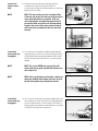
Remove the steering gear from the vehicle and take it to a clean surface (a piece of
wrapping paper makes an excellent disposable top)
Clean and dry the gear before you start to disassemble it.
As you disassemble the gear, clean all parts in clean, petroleum-based solvent, and
blow them dry only.
WARNING: SINCE THEY ARE FLAMMABLE, BE EXTREMELY CAREFUL WHEN
USING ANY SOLVENT. EVEN A SMALL EXPLOSION OR FIRE COULD CAUSE
INJURY OR DEATH. WARNING: WEAR EYE PROTECTION AND BE SURE TO
COMPLY WITH OSHA OR OTHER MAXIMUM AIR PRESSURE REQUIREMENTS.
CAUTION: Never steam clean or high-pressure wash hydraulic steering components. Do not force or abuse closely fitted parts.
•
•
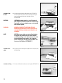
Keep each part separate to avoid nicks and burrs.
Discard all seals, O-rings, and gaskets removed from the gear. Replace them with new
parts only.
Disassembly
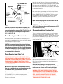
position gear &
sector shaft
CAUTION
remove protector
boot & dirt and
water seal
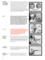
TIMING MARK
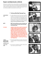
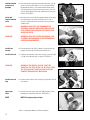
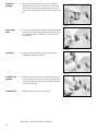
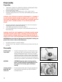
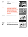
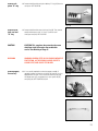
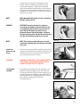
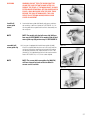
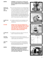
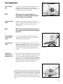
1. Position the steering gear firmly in a vise with the gear’s worm
shaft/input shaft (16) in a horizontal direction. Prepare for fluid
drainage and unplug fluid line ports. Rotate worm shaft/input
shaft with an 11/16 inch or 3/4 inch 12 point socket or box end
wrench, through the gear travel several times to purge hydraulic
fluid from the unit. Then position the timing mark located on the
end of the sector shaft (48) to a vertical direction. SEE FIGURE 40.
CAUTION: Clamp only against housing mounting
bosses or attach a plate to the mounting bosses for
this purpose. Do not clamp against the body of
housing.
Figure 40
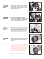
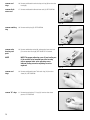
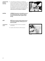
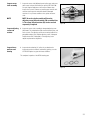
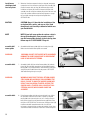
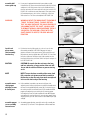
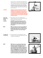
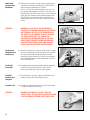
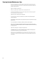
2. Remove protector boot (60), grease fitting (61) and the dirt and
water seal (26) from the trunnion cover (25). SEE FIGURE 41.
Discard boot and seal.
Figure 41
20