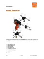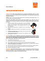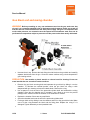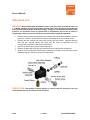
1
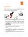
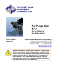
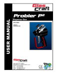
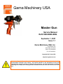
Gama Machinery USA
Master Gun
Service Manual
Ref # NR-00008-ENG
September 1, 2007
Issue 1.1
Gama Machinery USA, Inc.
55 LaFrance Ave
Bloomfield, NJ 07003
Phone: 973-429-5600
Fax: 973-429-5601
Copyright 2007, Gama-USA
http://www.gama-usa.com
Before installing the Master Gun and starting it up, carefully read all the technical and safety
documentation included in this manual. Pay special attention to the information to know and
understand the operation and the conditions of use of the gun. All of the information is aimed at
enhancing User Safety and avoiding possible breakdowns derived from the incorrect use of the
Gun.
Service Manual
WARRANTY
GARRAF MAQUINARIA, S. A. (hereinafter “GAMA”) provides this LIMITED WARRANTY (hereinafter “Warranty”) to the
original purchaser (hereinafter “Customer”) covering this equipment and the original GAMA manufactured accessories
delivered with the equipment (hereinafter “Product”) against defects in material or workmanship of the Product (hereinafter
“Defect” or “Defective”) for a period of two (2) years from the date of first purchase as shown on the original GAMA invoice
(hereinafter “Warranty Period”).
If during the Warranty Period under normal use, the Product is suspected by Customer to be Defective in material or
workmanship, it is Customer’s responsibility to contact GAMA and return the Product to GAMA as directed by GAMA, freight
prepaid. If GAMA determines that the Product is Defective and that such Defect is covered by this Warranty, GAMA will
credit Customer for the reasonable freight charges incurred by Customer in returning the Defective Product to GAMA, and
GAMA (or its authorized agent) will, at GAMA’s option, repair or replace the Product, subject to the following:
Original Invoice: The original invoice must be kept as proof of the date of first sale and the Product serial number. The
Warranty does not cover any Product if the Original Invoice appears to have been modified or altered, or when the serial
number on the Product appears to have been altered or defaced.
Product Maintenance: It is the Customer’s responsibility to maintain the Product properly. See your maintenance schedule
and owner’s manual for details. The Warranty does not cover an improperly maintained Product.
Non-GAMA Components and Accessories: Non-GAMA manufactured components and accessories that are used in the
operation of the Product are not covered by this Warranty. Such components and accessories shall be subject to the
warranty offered to the Customer, if any, by the original manufacturer of such component or accessory.
Other Warranty Exclusions: The Warranty does not cover any Product that GAMA determines has been damaged or fails to
operate properly due to misuse, negligence, abuse, carelessness, neglect, or accident. By way of example only, this
includes:
•
Normal wear an tear.
•
Improper or unauthorized installation, repair, alteration, adjustment or modification of the Product.
•
Use of heating devices, pumping equipment, dispensers, or other parts or accessories with the Product that have
not been approved or manufactured by GAMA.
•
Failure to follow the operating instructions and recommendations provided by GAMA.
•
Cosmetic damage.
•
Fire, flood, “acts of God,” or other contingencies beyond the control of GAMA.
THE WARRANTY DESCRIBED HEREIN IS THE EXCLUSIVE REMEDY FOR THE CUSTOMER AND IS IN LIEU OF ALL OTHER
WARRANTIES, EXPRESS, IMPLIED, STATUTORY OR OTHERWISE, AND THE IMPLIED WARRANTIES OF MERCHANTABILITY AND
FITNESS FOR A PARTICULAR PURPOSE AND ALL OTHER WARRANTIES ARE HEREBY DISCLAIMED. TO THE FULLEST EXTENT
PERMITTED BY LAW, GAMA SHALL NOT BE RESPONSIBLE, WHETHER BASED IN CONTRACT, TORT (INCLUDING, WITHOUT
LIMITATION, NEGLIGENCE), WARRANTY OR ANY OTHER LEGAL OR EQUITABLE GROUNDS, FOR ANY CONSEQUENTIAL,
INDIRECT, INCIDENTAL, LOST PROFITS, SPECIAL, PUNITIVE OR EXEMPLARY DAMAGES, WHETHER TO PERSON OR PROPERTY,
ARISING FROM OR RELATING TO THE PRODUCT, EVEN IF GAMA HAS BEEN ADVISED OF THE POSSIBILITY OF SUCH LOSSES OR
DAMAGES.
Non-Warranty Service by GAMA: If GAMA determines that the suspected Defect of the Product is not covered by this
Warranty, disposition of the Product will be made pursuant to the terms and conditions of GAMA’s written estimate on a time
and materials basis.
Continuing Warranty for Products Repaired or Replaced under Warranty: Following the repair or replacement of a Product
covered by this Warranty, such Product will continue to be subject to the original Warranty for the remainder of original
Warranty Period or for three (3) months from the repair or replacement date, whichever is longer.
No Rights Implied: Nothing in the sale, lease or rental of any Product by GAMA shall be construed to grant any right, interest
or license in or under any patent, trademark, copyright, trade secret or other proprietary right or material owned by anyone;
nor does GAMA encourage the infringement of same.
Exclusive Warranty: This writing is the final, complete, and exclusive expression of the Warranty covering the Product. Any
statements made by GAMA, its employees or agents that differ from the terms of this Warranty shall have no effect. It is
expressly understood that Customer’s acceptance of this Warranty, by performance or otherwise, is upon and subject solely
2/23
1.1 Issue
Ref. NR-00008-ENG
Service Manual
to the terms and conditions hereof, and any additional or different terms and conditions proposed or expressed by Customer
or anyone, whether in writing or otherwise, are null and void unless specifically agreed to in writing by an Officer of GAMA.
3/23
1.1 Issue
Ref. NR-00008-ENG
Service Manual
SAFETY AND HANDLING
This chapter contains important information on the safety, handling and use of your GAMA
MASTER series gun.
Before installing the Master gun and starting it up, carefully read all the
technical and safety documentation included in this manual. Pay special
attention to the information to know and understand the operation and the
conditions of use of the unit. All of the information is aimed at enhancing
User Safety and avoiding possible breakdowns derived from the incorrect use
of the gun.
WARNING! establishes information to alert on a situation that might cause serious injuries if
the instructions are not followed.
PRECAUTION! establishes information that indicates how to avoid damage to the gun or
how to avoid a situation that could cause minor injuries.
NOTE is relevant information on a procedure being carried out.
Careful study of this manual will enable the operator to know the characteristics of the gun and the
operating procedures. By following the instructions and recommendations contained herein, you
will reduce the potential risk of accidents in the installation, use or maintenance of the gun; you will
provide a better opportunity for incident-free operation for a longer time, greater output and the
possibility of detecting and resolving problems fast and simply.
Keep this Service Manual for future consultation of useful information at all times. If you lose this
manual, ask for a new copy from your GAMA local distributor or directly contact Gama Machinery
USA, INC.
Important Safety Information
The master gun has been designed and built for the application of polyurea chemical systems,
polyurethane foam chemical systems and some two-component epoxy systems.
WARNING: The design and configuration of the gun do not allow its use in potentially
explosive atmospheres or the pressure and temperature limits described in the technical
specifications of this manual to be exceeded.
Always use liquids and solvents that are compatible with the unit. In the event of doubt, consult the
GAMA technical service.
When working with the gun, it is recommended that the operator wear suitable clothing and
elements of personal protection, including, without limitation, gloves, protective goggles, safety
footwear and face masks. Use breathing equipment when working with the gun in enclosed spaces
or in areas with insufficient ventilation. The introduction and follow-up of safety measures must not
be limited to those described in this manual. Before starting up the gun, a comprehensive analysis
must be made of the risks derived from the products to be dispensed, the type of application and
the working environment.
4/23
1.1 Issue
Ref. NR-00008-ENG
Service Manual
To prevent possible injury caused by incorrect handling of the raw materials
and solvents used in the process, carefully read the safety data sheet
provided by your supplier.
Deal with the waste caused according to current regulations.
To avoid damage caused by the impact of pressurized fluids, do not open any
connection or perform maintenance work on components subject to pressure
until the pressure has been completely eliminated.
Use suitable protection when operating, maintaining or being present in the
area where the equipment is functioning. This includes, but is not limited to,
the use of protective goggles, gloves, shoes and safety clothing and
breathing equipment.
The equipment includes components that reach high temperatures and can
cause burns. Hot parts of the equipment must not be handled or touched
until they have cooled completely.
To prevent serious injury through crushing or amputation, do not work with
the equipment without the safety guards installed on the moving parts. Make
sure that all the safety guards are correctly reinstalled at the end of the repair
or maintenance work of the equipment
5/23
1.1 Issue
Ref. NR-00008-ENG
Service Manual
CHARACTERISTICS
* Internal mixture due to high pressure
* Automatic cleaning with pressurised air
* No solvents needed
* Mechanical spraying
* Exterior lubrication of the mix chamber
Approximate weight: 1 Kg / 2.2 lbs
Dimensions: H 19 cm / W 10 cm / L 19 cm
TECHNICAL SPECIFICATIONS
Maximum working pressure: ______________________ 210 Kgf/cm2 (20.6 MPa) / 3000 psi
Air pressure required: ________________________ 6-8 Kgf/cm2 (0.6-0.8 MPa) / 85-114 psi
Maximum production ratio 1:1: _______________________________ 18 Kg/min / 40 lb/min
Minimum production ratio 1:1:_______________________________ 1.5 Kg/min / 3.3 lb/min
Opening force @ 6 bar:____________________________________________ 90 Kg / 200 lb
Closing force @ 6 bar: ____________________________________________ 93 Kg / 205 lb
Approximate air consumption @ 6 bar (50 cycles/min): _______________ 307 litres/minute
6/23
1.1 Issue
Ref. NR-00008-ENG
Service Manual
GENERAL DESCRIPTION
For better knowledge of the elements forming the MASTER series gun, the main components and
their description are shown. For more precise identification, see the Components Manual ref. NR00004-ENG
1.
2.
3.
4.
5.
6.
7.
8.
9.
10.
7/23
Gun block unit
Polyol input block unit
Plastic/metal sealing kit
Polyol filter body
Polyol manual valve
Isocyanate input block unit
Isocyanate filter body
Isocyanate manual valve
Mix chamber
Trigger
1.1 Issue
Ref. NR-00008-ENG
Service Manual
11. Diffuser
12. Blocking device
8/23
1.1 Issue
Ref. NR-00008-ENG
Service Manual
INSTALLATION AND START-UP
PRECAUTION: When working with the gun or performing maintenance work on it, wear
suitable protection in accordance with the recommendations and specifications provided by
the product suppliers.
GAMA provides a series of tools and accessories that are necessary for assembling the gun. The
tool kit is made up of the following elements:
Metal brush, tube spanner, chuck, pliers for snap rings, spanner, set of allen keys, tube for
extension of pneumatic connection, tube of grease, nozzle stopper, greasing stopper, grease gun,
flexible pipe for air connection, fast plug, bits for cleaning, operations manual and component parts
ID manual.
1. Close the manual valves by turning them to the full clockwise
position. The manual valves control the flow of each product to the
chamber and are located on the Isocyanate input block and the
Polyol input block.
2. Press the safety stop and turn it clockwise to set it to the blocking
position.
3. Fit the air supply pipe and connect it to the connector on the rear of
the gun.
4. Connect the Isocyanate hose (red terminal) to the connection on the
Isocyanate input block (letter A).
5. Connect the Polyol hose (blue terminal) to the connection on the
Polyol input block. (letter R).
NB.: The product hoses are identified in red and blue, allowing the user to rapidly recognise
them. The red corresponds to the Isocyanate hose and the blue to the Polyol hose. To avoid
connection errors, the coupling connections of the Isocyanate and Polyol hoses are different
sizes, which makes it impossible to swap connections.
6.
7.
8.
9.
Connect the air supply to the gun.
Pressurise the gun and make sure there are no leaks.
Pull the trigger several times to check the correct movement of the mixing chamber.
Check that the pressure in the machine and the temperature of the heaters and the hoses is
correct (see the Machine Service Manual).
10. Open the manual valves of each product by turning them to the full counter clockwise position.
11. Press the safety stop and turn it counter clockwise to set it to the spray position.
12. Perform a test projection in a vessel
WARNING: Before performing maintenance, repair or cleaning work, press the safety stop
and turn it clockwise to set it to the blocking position, close the manual valves completely
and disconnect the air supply to avoid possible accidents.
9/23
1.1 Issue
Ref. NR-00008-ENG
Service Manual
The gun is designed with the flexibility to have the air input in the rear or at the base of the gun
handle. To make the change, do the following:
13. Disconnect the air pipe from the rear.
14. Unscrew the fitting at the rear of the gun.
15. Unscrew the existing plug at the base of the handle.
16. Screw the plug into the rear of the gun. Use Teflon tape or sealing paste to prevent air leaks.
17. Fit the air connection extension (optional) to the base of the handle. Use Teflon tape or sealing
paste to prevent air leaks.
18. Connect the air pipe.
10/23
1.1 Issue
Ref. NR-00008-ENG
Service Manual
SHUTDOWN PROCEDURES
1.
2.
3.
4.
5.
Close the manual valves of each product by turning them to the full clockwise position.
To eliminate the pressure from the gun, pull the trigger and project the gun until the projection
fan starts to reduce.
Press the safety stop and turn it clockwise to set it to the blocking
position
Disconnect the air supply from the gun.
Remove the cap and lubricate the mixing chamber with the grease
gun supplied in the tool kit; this action will prevent the cleaning air of
the gun from reacting with the ISOCYANATE product and avoiding
crystallization which may damage the chamber and cap.
NB.: The use of injecting lubrication into the gun at the end of the day will avoid
maintenance time, as it will not be necessary to remove the chamber each day to clean it.
PRECAUTION: To avoid possible contamination by the product remains deposited in the
components of the gun, do not exchange the Isocyanate parts with the Polyol parts. The gun
has the Isocyanate side identified with the letter A.
If the product hoses are pressurized, follow the Shutdown Procedures
indicated in the Machine Service Manual.
11/23
1.1 Issue
Ref. NR-00008-ENG
Service Manual
MAINTENANCE
To obtain maximum output from your MASTER gun, it is necessary to periodically perform certain
maintenance operations.
To prevent possible injury caused by incorrect handling of the raw materials
and solvents used in the process, carefully read the safety data sheet
provided by your supplier.
Deal with the waste caused according to current regulations.
To prevent serious damage caused by the impact of pressurised fluids, never
open a connection or perform maintenance work on components subject to
pressure until all pressure has been eliminated.
Use suitable protection when operating, maintaining or being present in the
area where the equipment is functioning. This includes, but is not limited to,
the use of protective goggles, gloves, shoes and safety clothing and
breathing equipment.
The equipment includes components that reach high temperatures and can
cause burns. Hot parts of the equipment must not be handled or touched
until they have cooled completely.
To prevent serious injury through crushing or amputation, do not work with
the equipment without the safety guards installed on the moving parts. Make
sure that all the safety guards are correctly reinstalled at the end of the repair
or maintenance work of the equipment
12/23
1.1 Issue
Ref. NR-00008-ENG
Service Manual
Gun block unit and mixing chamber
WARNING: Before proceeding to carry out maintenance work on the gun, make sure that
the unit is at a complete standstill, that all the buttons and the general switch are turned off
and that the unit is disconnected from the main power supply. The gun is a component that
works under pressure; no connection must be opened and maintenance work must not be
performed on components subject to pressure until the pressure has been totally eliminated.
•
Unscrew the air cap. Remove the bolts fixing the side blocks to the gun block and carefully
separate both blocks from the gun. Clean the contact surfaces using a cloth dampened in
gun-cleaning solvent.
PRECAUTION: Use wooden or plastic utensils or a brass brush for cleaning. Do not use
metal utensils that can scratch the contact surfaces.
•
Remove the gun block mounting bolts and separate the gun block by sliding it over the
chamber. To eliminate the residual product, clean the gun block unit using a cloth
dampened with gun cleaning solvent and a brass brush. Remove the o-ring.
•
Use a spanner to lock the end of the pneumatic cylinder shaft and unthread the mixing
chamber. Clean the mix chamber and, if necessary, use a brush to go over the product
passage holes. Make sure that the chamber is not scratched or marked.
•
Replace the chamber if there are any small faults.
•
Screw the chamber back onto the end of the pneumatic cylinder shaft.
•
Fit the gun block unit by sliding it over the chamber and fix it to the gun with the bolts. Make
sure to fit the o-ring between the block and the fixing plate. Replace the o-ring if it is
damaged. Tighten alternately to avoid possible leaks.
•
13/23
1.1 Issue
Ref. NR-00008-ENG
Service Manual
•
14/23
Fit the side blocks to the gun block with the corresponding bolts. Tighten alternately to
avoid possible leaks. Screw on the Air Cap. The gun is now ready for service.
1.1 Issue
Ref. NR-00008-ENG
Service Manual
Side block unit
WARNING: Before performing maintenance work on the gun, make sure that the unit is at
a complete standstill, that all of the buttons and the main switch are turned off and that the
unit is disconnected from the main power supply. The gun is a component that works under
pressure; no connection must be opened and no maintenance work must be done on
components subject to pressure until the pressure has been completely eliminated.
•
Remove the side block mounting bolts on the Polyol side and carefully separate it from the
gun block. Clean the contact surfaces using a cloth dampened in gun-cleaning solvent.
•
Unscrew the filter housing and remove the seal and the filter screen. Carefully clean the
filter with gun cleaning solvent and check that the mesh is completely free from
contaminants. Replace the filter screen as required.
•
Remove the check valve retainer from the side block.
•
Remove the parts and clean with gun cleaning solvent or replace them as required.
•
Clean all of the components meticulously to eliminate the remains of product using a cloth
dampened with gun cleaning solvent and a brass brush.
PRECAUTION: Use wooden or plastic utensils or a brass brush for cleaning. Do not use
metal utensils that can scratch the contact surfaces.
15/23
1.1 Issue
Ref. NR-00008-ENG
Service Manual
•
Reassemble the check valve and side seal assembly. For the model with the plastic seal, fit
the plastic seal cap in the retainer; fit the spring and then the check valve assembly.
•
In the model with a metal seal, you must fit the spring and the check valve into the retainer.
To facilitate assembly, use a little grease to fit the o-ring in the metal seal cap; make sure
that it is not damaged and replace it if necessary. Press the metal seal cap into the retainer
until the o-ring is fitted in its groove.
•
Hand-tighten the plastic/metal seal and retainer into the side block. If you use a spanner,
do not over tighten the retainer more than 1/4 of a turn.
PRECAUTION: Do not tighten the check valve retainer excessively. Tightening more than
1/4 of a turn can damage the plastic/metal check valve and cause leaks.
•
Check the wear on the plastic/metal seal, by measuring the distance that it stands out from
the cap housing. If the seal is worn, knocked or scratched, it can cause leaks. Replace the
seal if it stands out less than 1.65 mm / 1/16 inch.
•
To check whether the plastic/metal check valve is damaged as a result of excessive
tightening, make sure the separation between the support face of the side block and the
bottom of the cap housing, once fitted, is 0.46 mm / 1/64 inch. If the separation is smaller,
the check valve must be replaced.
•
Assemble the screen screw and screw it into the side block.
•
Fix the Polyol side block onto to the gun block with the corresponding bolts. Tighten
alternately to avoid possible leaks.
•
Perform the same steps with the side block on the Isocyanate side.
•
The gun is now ready for service.
16/23
1.1 Issue
Ref. NR-00008-ENG
Service Manual
Trigger and valve
WARNING: Before performing maintenance work on the gun, make sure that the unit is at
a complete standstill, that all of the buttons and the main switch are turned off and that the
unit is disconnected from the main power supply. The gun is a component that works under
pressure; no connection must be opened or maintenance work done on components subject
to pressure until the pressure has been completely eliminated.
•
Remove the side blocks and carefully separate them from the gun block. Clean the contact
surfaces using a cloth dampened in gun cleaning solvent.
•
If the gun has the air inlet on the rear (standard) disconnect the air pipe and the connection.
•
If the inlet is at the base of the handle (optional), unscrew the cap from the rear of the gun.
•
Remove the retention ring and take out the pin fixing the trigger.
•
Unscrew the nut of the trigger valve.
•
Remove the trigger valve and carefully hold the end of the trigger shaft with pliers to
remove it from its housing. The trigger shaft has a spring inside it; make sure you don't lose
it.
•
Check the o-rings of the trigger valve and the trigger shaft. Replace them if they are
damaged. Apply a little grease to facilitate the fitting.
•
Remove the existing cap at the bottom of the housing at the rear of the gun.
•
The trigger valve seat is housed at the bottom. Insert a punch with a maximum diameter of
6 millimetres in the rear, and use a hammer to tap on the base of the seat until it is
completely out of the housing.
•
Make sure the housing is clean, and apply a layer of grease on the inside.
17/23
1.1 Issue
Ref. NR-00008-ENG
Service Manual
•
Slide the seat of the trigger valve in the housing, make sure that the edge is on the outside.
•
Insert the trigger valve in the housing, taking special care not to damage the o-rings. You
will note a certain resistance caused by the interference of the seals with the wall of the
housing. Insert it until you see the first lines of the thread.
•
Screw in the cap, using sealing paste to prevent air leaks.
•
Fit the air connection and hose on the rear of the gun. If the gun has the air inlet on the
base of the handle, screw the cap into the inlet on the rear, using sealing paste to prevent
air leaks.
•
Insert the spring on the trigger shaft and insert this inside the trigger valve.
•
Tighten the trigger valve nut until it is fitted. Do not tighten excessively.
•
Fit the trigger with the pin and fix it with the retention ring.
•
Fix the product input blocks to the gun block with the corresponding bolts. Tighten
alternately to avoid possible leaks.
•
The gun is now ready for service.
18/23
1.1 Issue
Ref. NR-00008-ENG
Service Manual
Cylinder block and blocking device
WARNING: Before performing maintenance work on the gun, make sure that the unit is at
a complete standstill, that all of the buttons and the main switch are turned off and that the
unit is disconnected from the main power supply. The gun is a component that works under
pressure; no connection must be opened or maintenance work done on components subject
to pressure until the pressure has been completely eliminated.
•
Remove the side blocks and carefully separate them from the gun block.
•
Clean the contact surfaces with a cloth dampened in gun cleaning solvent.
•
Unscrew the bolt fixing the clamp on the rear of the gun.
•
Remove the retaining ring from the cylinder using the snap ring pliers.
•
Pull hard on the safety stop to remove the whole unit from the cylinder. Also remove the
plunger spring.
•
Check the state of the o-ring seal on the end cap. Replace it if it is damaged.
•
Apply a little grease to facilitate the placement of the o-ring.
•
Loosen the two set screws on the safety stop. Remove the stop pin and the stop spring
from the device.
•
Remove the end cap from the stop pin.
•
Remove the lip seal from the end cap and replace it if it is damaged. Apply a little grease to
facilitate the fitting.
•
Pay attention to the correct installation of the lip seal: The seal lips must face forward.
•
Fit the end cap onto the stop pin. Slide the spring and the safety stop onto the stop pin.
Tighten the two set screws making sure that they are perfectly aligned with the flats on the
end of the stop pin. Make sure that the blocking device is well-fitted.
19/23
1.1 Issue
Ref. NR-00008-ENG
Service Manual
•
Insert the spring in the rear housing of the plunger. Insert the end cap into the cylinder bore
by pressing until it passes the insertion groove of the retention ring.
•
Fit the retention ring using snap ring pliers.
WARNING: To assure that the end cap is well-fitted, make sure that the retention ring is
perfectly fitted in the fixing groove. To avoid possible errors in assembly, avoid approaching
the cylinder block when applying pressure to the gun after cleaning, repair or maintenance
operations.
•
Fit the clamp and fix it with the bolt to the rear of the gun.
•
Fix the side blocks to the gun block with the corresponding bolts.
•
Tighten alternately to avoid possible leaks.
•
The gun is now ready for service.
20/23
1.1 Issue
Ref. NR-00008-ENG
Service Manual
Pneumatic cylinder
WARNING: Before performing maintenance work on the gun, make sure that the unit is at
a complete standstill, that all of the buttons and the main switch are turned off and that the
unit is disconnected from the main power supply. The gun is a component that works under
pressure; no connection must be opened or maintenance work done on components subject
to pressure until the pressure has been completely eliminated.
•
Unscrew the air cap. Remove the side blocks from the gun block. Clean the contact
surfaces using a cloth dampened with gun cleaning solvent.
•
Remove the gun block from the gun by sliding it over the chamber. To eliminate the
remains of product, clean the gun block unit using a cloth dampened with gun cleaning
solvent. Remove the o-ring.
•
Use a spanner to lock the end of the pneumatic cylinder shaft and unthread the mixing
chamber. Clean the mixing chamber and, if you consider it necessary, use a brush to go
over the passage holes.
•
Remove the cylinder clamp.
•
Using the snap ring pliers, remove the retaining ring holding the end cap.
•
Pull hard on the blocking device to remove the whole unit from the cylinder bore. Also
remove the spring and the piston assembly from inside the cylinder.
•
Using the snap ring pliers, remove the snap ring from the piston shaft and separate it from
the piston.
•
Check the state of the o-rings of the shaft and piston. Replace them if they are damaged.
Apply a little grease to facilitate the fitting.
•
Fit the piston by sliding it onto the shaft taking special care not to damage the o-rings. Fit
the retention ring.
•
Fit the piston assembly into the cylinder bore.
•
Insert safety stop assembly into the cylinder bore until it passes the insertion groove of the
retention ring.
21/23
1.1 Issue
Ref. NR-00008-ENG
Service Manual
•
Fit the retention ring using the snap ring pliers.
WARNING: To Warranty that the cylinder block is well-fitted, make sure that the retention
ring is perfectly fitted in the fixing groove. To avoid possible errors in assembly, avoid
approaching the end cap when applying pressure to the gun after cleaning, repair or
maintenance operations.
•
Install the cylinder clamp.
•
Hand-tighten the mix chamber while holding the end of the pneumatic cylinder with a
spanner.
•
Assemble the gun block by sliding it over the chamber and fix it to the gun with the bolts.
Make sure to fit the o-ring between the block and the fixing plate and replace it if it is
damaged. Tighten alternately to avoid possible leaks.
•
Assemble the side blocks to the gun block with the corresponding bolts. Tighten alternately
to avoid possible leaks. Screw on the diffuser.
•
The gun is now ready for service.
22/23
1.1 Issue
Ref. NR-00008-ENG
Service Manual
CONTENT
Important Safety Information_____________________________________________________ 4
Gun block unit and mixing chamber ______________________________________________ 13
Side block unit ______________________________________________________________ 15
Trigger and valve ____________________________________________________________ 17
Cylinder block and blocking device_______________________________________________ 19
Pneumatic cylinder ___________________________________________________________ 21
23/23
1.1 Issue
Ref. NR-00008-ENG