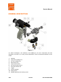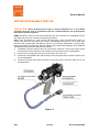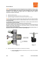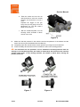
1
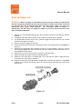
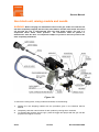
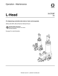
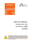
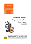
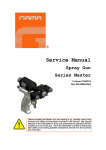
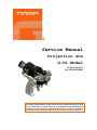
Service Manual
Projection Gun
G-DI Model
1.4 Issue 23/03/11
Ref. NR-00029-ENG
Before installing and operating the G-DI gun, carefully read the technical
and safety documentation in this manual. Special attention should be paid
to the information in order to know and understand the handling and
conditions of use of the Unit. All of the information is aimed at enhancing
User Safety and avoiding possible faults due to incorrect use of the Unit.
Service Manual
WARRANTY
GARRAF MAQUINARIA, S. A. (hereinafter “GAMA”) grants this LIMITED WARRANTY to the original
buyer (hereinafter the “Client”) for the unit and the original accessories given with the unit (hereinafter the
“Product”) against any fault in the design, materials or manufacture of the Product at the time of the first
purchase by the user and for a duration of two (2) years thereafter.
If during the period of guarantee and under normal conditions of use, the Product should stop working
properly due to faults in the design, the materials or the manufacture, the authorised distributor in the
country where the Product has been purchased or the GAMA technical service will repair or replace the
Product in accordance with what is established in the following
CONDITIONS
a) The validity of this guarantee will be subject to the presentation of the original invoice issued by
the GAMA authorised distributor for the sale of the Product along with the Product handed over
for repair or replacement, which must show the date of purchase and the serial number. GAMA
reserves the right to refuse to give the guarantee service when the indicated data fail to appear
on the invoice or have been modified after the purchase of the Product.
b) The repaired or replaced Product will continue to maintain the original guarantee during the time
remaining until its end, or for three (3) months after the repair date, if the remaining period of the
guarantee were shorter.
c) This guarantee will not be applied to the faults in the Product caused by its faulty installation, the
natural wear and tear of the components, any use other than that considered normal for this
Product or which should fail to strictly comply with the instructions of use provided by GAMA; due
to accident, carelessness, adjustments, alterations or modifications of the Product not authorised
by GAMA or due to the use of accessories, heating devices, pumping equipment and/or
dispensers that have not been approved or manufactured by GAMA.
d) The guarantee applicable to the components and accessories forming part of the Product and
which have not been made by GAMA will be limited to the guarantee offered by the original
manufacturer thereof.
GAMA WILL NOT RECOGNISE ANY EXPRESS ORAL OR WRITTEN GUARANTEES OTHER THAN THIS PRINTED LIMITED
GUARANTEE. ALL IMPLICIT GUARANTEES, INCLUDING, WITHOUT LIMIT, ADAPTATION FOR A SPECIFIC USE, ARE SUBJECT
TO THE DURATION OF THIS WRITTEN GUARANTEE. GAMA DOES NOT ASSUME ANY KIND OF COMMITMENT OR
RESPONSIBILITY FOR ALL POSSIBLE DAMAGE OR EXPENSE CAUSED BY FAULTS IN THE OUTPUT OF THE PRODUCT, ITS
WORKING OR THE DISPENSING OF MATERIAL THROUGH THE PRODUCT, INCLUDING, WITHOUT LIMITATION, ALL
EXPENSES CAUSED BY DAMAGE TO PEOPLE OR PROPERTY. EQUALLY, GAMA WILL IN NO CASE ACCEPT LIABILITY FOR
THE LOSS OF SPECULATIVE PROFITS OR COMMERCIAL LOSSES. ALL REPAIRS OR REPLACEMENT OF FAULTY PRODUCTS
WILL CONSTITUTE THE COMPREHENSIVE FULFILMENT OF GAMA'S OBLIGATIONS WITH RESPECT TO THE CLIENT. GAMA IN
NO WAY GUARANTEES THE IDEALNESS OR SUITABILITY OF ITS PRODUCT FOR ANY PURPOSE OR SPECIFIC APPLICATION.
All of the information provided on components which have not been manufactured by GAMA and which is
based on reports received from the original manufacturer, though considered precise and reliable, is
provided without any guarantee or responsibility of any explicit or implicit kind.
All concession, sale or financial leasing of the Product by GAMA in no case explicitly or implicitly
constitutes any authorisation, acceptance or concession for the use of any rights or patents, nor does it
encourage, nurture or back their infringement.
The restrictions on the guarantee suppose no limitation on the legal rights of the consumer established in
applicable national legislation, nor do they affect any rights derived from the bargain and sale agreement
between the consumer and supplier.
2/28
1.4 Issue
Ref. NR-00029-ENG
Service Manual
All of the information provided in this Service Manual has been included in the confidence that it
is true, although it does not constitute any responsibility or implicit or explicit guarantee. GAMA
reserves the right at any time without forewarning to make all necessary improvements and
modifications to this Service Manual in order to rectify any possible typographical errors,
increase the information contained and enter the changes made to the characteristics and
performances of the gun.
SAFETY AND HANDLING
This chapter contains important information on safety, handling and the use of your GAMA G-DI
series gun.
Before installing and operating the G-DI gun, carefully read the technical
and safety documentation in this manual. Special attention should be paid
to the information in order to know and understand the handling and
conditions of use of the gun. All of the information is aimed at enhancing
User Safety and avoiding possible faults due to incorrect use of the gun.
A WARNING! establishes information for alerting you on the situations which could
cause serious injury if the instructions are not followed.
A PRECAUTION! establishes information which indicates how to avoid damage to the
gun and how to avoid a situation which could cause minor injuries.
A NOTE is relevant information on the procedure being carried out.
Careful study of this manual will help you to become more acquainted with the gun and the
procedures. Following the instructions and recommendations here will reduce the potential risk
of accidents in installing, using or maintaining the gun, and will give you the problem-free
operation for a longer time, greater output and the possibility of detecting and resolving
problems quickly and simply.
Keep this Service Manual for consultation and useful information at any time. If you lose the
manual, ask for a new copy from your local GAMA distributor or make direct contact with Garraf
Maquinaria, S. A.
WARNING: The gun's design and configuration do not allow it to be used in potentially
explosive atmospheres or to exceed the pressure and temperature limits described in the
technical specifications of this manual.
Always use liquids and solvents that are compatible with the unit. In the event of doubt, consult
the GAMA technical service.
3/28
1.4 Issue
Ref. NR-00029-ENG
Service Manual
When working with the gun, it is essential to dress suitably and use personal protection
equipment, including the unlimited use of gloves, protective goggles, safety footwear and face
masks. Use breathing equipment when working with the gun in enclosed or insufficiently
ventilated atmospheres. The introduction and monitoring of safety measures must not be limited
to those described in this manual. Before starting to use the gun, a rigorous analysis must be
made of the risks derived from the products to be dispensed, the type of application and the
working environment.
The gun forms part of the projection equipment, which is why all safety measures must be taken
that are provided for the start-up use of the equipment, in addition to all specific measures for
the use of the gun.
Carefully read the safety data sheet provided by your supplier to prevent
any possible injury caused by incorrect handling of the raw materials and
solvents used in the process.
Deal with all waste caused according to current regulations.
To prevent serious damage caused by the impact of fluids under
pressure, never open a connection or do maintenance work on
components subject to pressure until you are sure that all pressure has
been eliminated.
Use suitable protection when operating, maintaining or simply being in
the area where the equipment is working. This includes, but is not limited
to, the use of protective goggles, gloves, shoes and safety clothes and
breathing equipment.
The equipment includes components which reach high temperatures and
may cause burns. The hot parts of the unit must not be handled or
touched until they have completely cooled.
To prevent serious injury caused by crushing or amputations, do not work
with the equipment if the moving part safety protections are not duly
installed. Make sure that all safety protections are correctly fitted after
carrying out repair or maintenance work on the equipment
4/28
1.4 Issue
Ref. NR-00029-ENG
Service Manual
CHARACTERISTICS
The new G-DI gun with a mechanical self-cleaning system has been designed for professional
appliers, giving a better mixing quality than any other gun on the market in applying Polyureas,
chemical systems for polyurethane foaming and some two-component epoxy systems.
It is exceptionally versatile. Its special configuration offers the possibility of working with flows of
0.5 Kg/minute to 18 Kg/minute and achieving different fan shapes and widths. Thus giving great
precision and maximum finishing quality in “in situ” and industrial applications.
The G-DI model is light, perfectly balanced and easy to maintain thanks to the new GAMA entry
block, fast-connecting and disconnecting.
* High-pressure internal mixture
* Mechanical automatic cleaning
* No solvents required
* Airless spraying
* Automatic greasing of the mix chamber
Approximate weight: 1.4 Kg
Dimensions: H 20 cm / W 10 cm / L 21 cm
SPECIFICATIONS
Maximum working temperature: _____________________________________ 90º C /194º F
Maximum working pressure: _______________________ 270 Kgf/cm2 (26.5 MPa) / 3840 psi
Minimum working pressure required: ____________________ 7 Kgf/cm2 (0.7 MPa) / 100 psi
Maximum production ratio 1:1: _______________________________ 18 Kg/min / 44 lb/min
Minimum production ratio 1:1: ______________________________ 0.5 Kg/min / 1.1 lb/min
Opening force @ 7 Kgf/cm2: _______________________________________ 190 Kg / 364 lbf
Closing force @ 7 Kgf/cm2: _______________________________________ 190 Kg / 364 lbf
Approximate air consumption @ 7 Kgf/cm2 (50 cycles/min): ____________ 60 litres/minute
5/28
1.4 Issue
Ref. NR-00029-ENG
Service Manual
GENERAL DESCRIPTION
Figure. 1
For better knowledge of the elements of the G-DI gun, the main components and their
description are shown. For a more precise identification, see the Components Manual ref. NR00028.
1.
2.
3.
4.
5.
6.
7.
8.
9.
10.
11.
6/28
Mixhead
Polyol side cartridge unit
Iso side cartridge unit
Block fixture bolt
Polyol manual valve
Isocyanate manual valve
Entry block fixture bolt
Trigger
Air flow regulator
Safety device
Needle adjustment nut blocking screw
1.4 Issue
Ref. NR-00029-ENG
Service Manual
Before continuing with the following procedures, familiarise yourself with the parts of the mix
head, so that you know the part referred to when you read this manual.
Figure .2
1.
2.
3.
4.
5.
6.
7.
8.
9.
10.
11.
12.
13.
14.
15.
Cartridge housing
Cartridge seal
Filter
Non-return
Diffuser
PCD nut
PCD
Module nut
Mixing module
Entry block seals
Coupling block
Rear closing seal
Rear closing seal nut
Needle
Needle adjustment nut
7/28
1.4 Issue
Ref. NR-00029-ENG
Service Manual
INSTALLATION AND START-UP
PRECAUTION: When working with the gun or doing maintenance on it, all suitable
protection must be used in accordance with the recommendations and specifications
given by the product suppliers.
GAMA provides a series of tools and accessories that are necessary for assembling the gun
(KT-00004-00). The unit comprises the following elements:
Metal brush (KT-00013-01), tube spanner (KT-00013-02), chuck (KT-00013-09), pliers for
seeger rings DIN 472 (KT-00013-04), sockets (HT-00038/39/40/41/42/43), set of Allen keys
(KT-00011-06), grease tube (OR-00012), pipe for air connection (MA-00027), fast plug (RA00109), fast plug pin (RA-00110), drills for cleaning (see Components Manual), Service Manual
(NR-00029) and Components Manual (NR-00028).
1. Completely close the manual valves by turning them clockwise. The manual valves control
the input flow of each product to the chamber and are located on the Coupling Block.
2. Connect the air supply pipe to the connector at the rear of the gun.
3. Connect the Isocyanate hose (red terminal) to the Isocyanate input connector (letter A) on
the Coupling Block.
4. Connect the Polyol hose (blue terminal) to the Polyol input connector (letter R) on the
Coupling Block.
Figure .3
8/28
1.4 Issue
Ref. NR-00029-ENG
Service Manual
NOTE: The product hoses have been distinguished with red and blue in order to allow
them to be rapidly identified. The red corresponds to the Isocyanate hose and the blue
corresponds to the Polyol hose. However, to avoid connection errors, the coupling
connectors of the Isocyanate and Polyol hoses are of different sizes to make it
impossible to swap the connections.
5.
6.
7.
Open the manual air valve.
Pressurise the unit and make sure there are no leaks in the gun.
Squeeze the trigger several times to make sure the needle moves correctly.
NB: The G-DI Gun gives an excellent mixing quality and a perfect fan, when the remains
of the two mixed chemical products are totally eliminated from the mix chamber with the
self-cleaning needle.
It is absolutely essential that when the needle closes, it makes perfect contact with the
internal spherical surface of the PCD.
To achieve a suitable contact, the G-DI Gun has an adjustment system.
Pay special attention when adjusting, for excessive contact can cause early wear and
damage to the needle. Little contact can leave product remains in the cavity, causing
incorrect mixture and fan deformation.
The approximate size that should protrude from the needle tip module (measurement ”A”
dimension) is 2.2 mm for 0.98 and 2.4 mm for 1.25 (see Figure. 4).
Figure. 4
8.
Figure .5
Adjust the needle in the firing position as indicated in the following:
a. Unscrew the Needle Regulation Nut Blocking Screw by turning it anti-clockwise
as show the Figure .5.
9/28
1.4 Issue
Ref. NR-00029-ENG
Service Manual
b. Take the socket and turn the nut
(anti-clockwise to move the needle
forward, and clockwise to move it
back.
Squeeze the trigger of the gun
every time you are going to turn the
adjustment nut. This will make it
easier to turn the nut.
c.
With the needle adjusted, turn the
blocking screw clockwise to block
the nut once more.
Figure. 6
9.
Make sure that the pressure in the machine and the temperature of the heaters and the
hoses are correct (see the Machine Service Manual).
10. Completely open the manual valves of each product by turning them anti-clockwise.
11. Press the safety device and turn it anti-clockwise to set it to the working position.
NB: The G-DI Gun has two positions, one for standstill or blocking and the other for
working. In the standstill position, the needle is drawn back, but still blocks the chemical
product outlet holes. In the working position, the needle is drawn back, leaving the
product holes free.
Figure. 7
10/28
Figure. 8
1.4 Issue
Ref. NR-00029-ENG
Service Manual
When it stops projecting, always turn the safety device to the blocking position to avoid
any kind of accidental damage when handling the gun.
12. Check the air regulator. Turn it anti-clockwise for an airflow that cleans any remains of
product that might be at the tip of the PCD and on the needle. Excessive air will distort the
projection fan. To completely close the air, turn it clockwise.
13. Carry out a test projection in a vessel.
WARNING: Before doing maintenance, repair or cleaning work, press the safety device
and turn it clockwise to leave it in blocking position, always remove the Coupling Block
from the gun, completely close the manual product input valves and disconnect the air
supply to avoid any possible accidents.
STOPPING METHOD
When stops are made of over 30 minutes, the non-return units of each product must be
checked and cleaned, as well as the filters, chamber and PCD. (See the Maintenance section
on page 17).
Perform the following steps to ensure correct operation:
1. Perform the Unit Standstill Method with the procedure indicated in the Machine Service
Manual.
2. Completely close the manual valves of each product by turning them clockwise.
3. To eliminate the pressure from the gun, press the trigger and project with the gun until the
projection fan begins to narrow.
4. Press the safety device and turn it clockwise to leave it in standstill or blocked position (see
Figure. 8, page 10).
5. Remove the coupling block from the gun. Use a cloth dampened with solvent to clean the
contact surfaces and the seals of the coupling block.
6. Remove the non-return unit and filter from the Polyol side on the mixing block. Clean the
unit with gun-cleaning solvent and also the block housing (see Figure. 19, page 18).
7. Remove the non-return unit and filter from the Isocyanate side on the mixing block. Clean
the unit with gun-cleaning solvent and also the block housing (see Figure. 19, page 18).
8. Remove the filters. Clean them carefully with gun-cleaning solvent, making sure that the
mesh is completely free of product remains. Clean and dry the housing well.
PRECAUTION: To avoid spilling the rest of the product which has accumulated in the
side cartridges onto the floor, always remove the coupling block and the side cartridges
on a waste vessel.
11/28
1.4 Issue
Ref. NR-00029-ENG
Service Manual
9.
Remove the diffuser and the PCD nut, turn them
anti-clockwise with your hand and clean them with
gun-cleaning solvent (see Figure. 9).
10. Remove the PCD and clean it with gun-cleaning
solvent (see Figure. 10).
Pay special attention in cleaning the interior
spherical area.
To facilitate the removal of the PCD, squeeze the
gun trigger 2 or 3 times. If it can not be removed by
hand, use some pliers to hold it and pull it out.
Figure. 9
Figure. 10
11. Unscrew the module tightening nut by turning it anti-clockwise.
12. Remove the mixing module from its housing and clean it with gun-cleaning solvent
If the product holes are blocked, clean them with the drills supplied along with the module
(see Figure. 11).
Clean the conic housing of the module on the head
using paper dampened with gun-cleaning solvent.
Do not use metal elements to clean the conic
housing, a scratch on the surface could cause it to
close badly with the module and this might cause
leaks of the chemical products.
To facilitate the removal of the module, squeeze
the gun trigger 1 or 2 times for the needle to move
back and forward. This movement will enable the
module to be removed from its conic housing. Now
pull on it with your hand to remove it from the
needle.
Figure. 11
13. Clean the part of the needle that protrudes from the mixhead with a paper dampened with
gun-cleaning solvent.
14. Refit all of the components and put the coupling block in the gun.
The gun is ready to go back into operation.
12/28
1.4 Issue
Ref. NR-00029-ENG
Service Manual
At the end of the working day, the state of the needle must be checked (See the
Maintenance section). Complete steps “1” to “11” above and perform the following
operations:
1.
2.
3.
Remove the safety device by pressing it and turning it anti-clockwise.
Remove the spring in the head of the pneumatic cylinder (see Figure. 12).
Turn the closing seal nut anti-clockwise until it no longer presses on the seal (see Figure.
13).
Figure. 12
4.
Figure. 13
Insert the end of the socket wrench into the hexagon of the needle and insert a socket in
the hexagon of the plunger shaft to prevent it from turning (see Figure. 14 and Figure. 15).
Turn anti-clockwise until the needle is completely removed from its housing.
Figure. 14
13/28
Figure. 15
1.4 Issue
Ref. NR-00029-ENG
Service Manual
5.
6.
7.
8.
Remove the needle and make sure there are no solid parts adhered to the needle, clean
with gun-cleaning solvent.
Loosen the rear seal nut completely by turning it anti-clockwise (see Figure. 16).
Clean the conic housing of the nut with paper dampened in gun-cleaning solvent. Do not
use metal elements to clean the conic housing, a scratch on the surface could cause it to
close badly with the module and this might cause leaks of the chemical products.
Remove the rear closing seal and clean it with gun-cleaning solvent or replace it if it is very
worn (see Figure. 16).
Clean the conic housing of the seal on the head using paper dampened with gun-cleaning
solvent. Do not use metal elements to clean the conic housing, a scratch on the surface
could cause it to close badly with the module and this might cause leaks of the chemical
products.
Figure. 16
9.
Refit all of the components and put the coupling block in the gun.
The gun is ready to go back into operation.
14/28
1.4 Issue
Ref. NR-00029-ENG
Service Manual
INSTALLATION OF THE MIXING MODULE AND PCD
1. Put the gun in a support or a vice where it can be held firmly, to be able to clean it with your
two hands without it moving.
2. Make sure that the conic housing of the mix head is clean and that its surface is not
damaged.
3. Put “GAMA” grease on the threads of the tightening nut of the module and in the threaded
housing of the mix head.
4. Insert the module on the tip of the needle, bearing in mind that the metal positioning pin is in
line with the non-turning hole of the mix head.
5. Press the front of the mixing module with your hand while squeezing the trigger for the
needle to move back.
6. The module positioning pin must have been inserted in the non-turning hole of the mixhead.
7. Without releasing the trigger, fit the tightening nut of the module, turning it clockwise.
8. Screw on the nut by hand as far as possible. Now using a socket, tighten the nut clockwise.
Release the trigger and make sure the needle moves forward. Squeeze the trigger 2 or
3 times to make sure that the needle moves backward and forward correctly.
9. Make sure that the rear closing seal nut it tight, if not, turn it clockwise.
BEWARE: Take special care when tightening the module and the rear closing seal nuts
with a socket.
Excessive tightening could mean that the pneumatic cylinder will not have sufficient
force to be able to move the needle. If it is too loose, it might cause leakage from the
mixing module.
10. Place the PCD in the module and press until the interior side comes into contact with the
front of the module.
If you have fitted a PCD for a flat fan, remember to turn the groove to the preferred
projection position (see Figure. 17 and Figure. 18).
Figure. 17
15/28
Figure. 18
1.4 Issue
Ref. NR-00029-ENG
Service Manual
11. Hand tighten the tightening nut of the PCD, clockwise. Make sure the groove does not move
out of position while tightening.
12. Adjust the needle as indicated in point 8 of Installation and Start-up (see page 9).
13. Hand fit the diffuser, turning it clockwise
14. Follow the instructions of points 9 to 13 of the Installation and Start-up (see page 10 and
page 11).
16/28
1.4 Issue
Ref. NR-00029-ENG
Service Manual
MAINTENANCE
To get the most out of your G-DI gun, certain periodical maintenance operations must be
carried out.
Carefully read the safety data sheet provided by your supplier to prevent
any possible injury caused by incorrect handling of the raw materials and
solvents used in the process.
Deal with all waste caused according to current regulations.
To prevent serious damage caused by the impact of fluids under
pressure, never open a connection or do maintenance work on
components subject to pressure until you are sure that all pressure has
been eliminated.
Use suitable protection when operating, maintaining or simply being in
the area where the equipment is working. This includes, but is not limited
to, the use of protective goggles, gloves, shoes and safety clothes and
breathing equipment.
The equipment includes components which reach high temperatures and
may cause burns. The hot parts of the unit must not be handled or
touched until they have completely cooled.
To prevent serious injury caused by crushing or amputations, do not work
with the equipment if the moving part safety protections are not duly
installed. Make sure that all safety protections are correctly fitted after
carrying out repair or maintenance work on the equipment
17/28
1.4 Issue
Ref. NR-00029-ENG
Service Manual
Side cartridge unit
WARNING: Before carrying out maintenance work on the gun, make sure that the unit
has been completely stopped, that all of the push buttons and the main switch are turned
off and that the unit is disconnected from the main power supply. The gun is a
component which works under pressure.
No connection must be opened or
maintenance work be done on component subject to pressure until the pressure has
been completely eliminated.
1.
Perform the Unit Standstill Method with the procedure indicated in the Machine Service
Manual.
2. Completely close the manual valves of each product by turning them clockwise.
3. To eliminate the pressure from the gun, press the trigger and project with the gun until the
projection fan begins to narrow.
4. Disconnect the air supply from the gun.
5. Press the safety device and turn it clockwise to leave it in blocked position (see Figure. 8,
page 10).
6. Unscrew the Isocyanate side cartridge by turning it anti-clockwise, remove it from its
housing (see Figure. 19). Clean the housing with gun cleaning solvent and make sure no
loose particles remain inside.
7. Remove the non-return unit and clean it with gun-cleaning solvent.
8. Remove the filter and clean it with gun cleaning solvent.
9. Make sure the mesh filter is not obstructed. If you see that the mesh is obstructed over
more than 20% of its surface, replace it.
10. Make sure the holes of the filter holder cartridge are not blocked by remains of crystallised
product. If you should see any dirt, clean the communicating drill holes with a drill and a
brass brush.
Figure. 19
18/28
1.4 Issue
Ref. NR-00029-ENG
Service Manual
PRECAUTION! Use wooden or plastic utensils or a brass brush for cleaning. Do not
use metal utensils that can scratch the surface.
11. Check the cartridge seal. Replace it if it is worn or damaged.
12. Grease all of the components and refit them in the cartridge.
13. Screw the isocyanate cartridge unit into its housing until it blocks. Make sure it is correctly
tightened to avoid product leaks.
14. Do the same with the polyol cartridge.
15. Carry out the projection procedure indicated in the section on Installation and Start-up (see
page 8).
16. Start the gun.
19/28
1.4 Issue
Ref. NR-00029-ENG
Service Manual
Gun block unit, mixing module and needle
WARNING: Before carrying out maintenance work on the gun, make sure that the unit
has been completely stopped, that all of the push buttons and the main switch are turned
off and that the unit is disconnected from the main power supply. The gun is a
component which works under pressure.
No connection must be opened or
maintenance work be done on component subject to pressure until the pressure has
been completely eliminated.
Figure .20
To remove the mixing block, mixing module and needle, do the following:
1.
2.
3.
Perform the unit Stopping method with the procedure given in the Machine Service
Manual.
Completely close the manual valves of each product by turning them clockwise.
To eliminate the pressure from the gun, press the trigger and project with the gun until the
projection fan begins to narrow.
20/28
1.4 Issue
Ref. NR-00029-ENG
Service Manual
4.
5.
6.
Press the safety device and leave it in blocked position.
Remove the coupling block.
Use a cloth dampened with solvent to clean the contact surfaces and the seals of the
coupling block.
PRECAUTION: To avoid spilling the rest of the product which has accumulated in the
side cartridges onto the floor, always remove the coupling block and the side cartridges
on a waste vessel.
7.
8.
9.
10.
11.
12.
13.
Remove the diffuser and the PCD nut by turning them anti-clockwise with your hand and
clean them with gun-cleaning solvent (see Figure. 9 page 12).
Remove the PCD and clean it with gun-cleaning solvent (see Figure. 10 page 12).
Pay special attention in cleaning the interior spherical area.
To facilitate the removal of the PCD, squeeze the gun trigger 2 or 3 times. If it can not be
removed by hand, use some pliers to hold it and pull it out.
Unscrew the module tightening nut by turning it anti-clockwise (see Figure. 11 page 12).
Remove the mixing module from its housing and clean it with gun-cleaning solvent (see
Figure. 11 page 12).
If the product holes are blocked, clean them with the drills supplied along with the module.
Clean the conic housing of the module in the head with paper dampened in gun cleaning
dissolvent. Do not use metal elements to clean the conic housing, a scratch on the surface
could cause it to close badly with the module and this might cause leaks of the chemical
products.
To facilitate the removal of the module, squeeze the gun trigger 1 or 2 times for the needle
to move backwards and forwards. This movement will enable the module to be removed
from its conic housing. Now pull on it with your hand to remove it from the needle.
Disconnect the air supply from the gun.
Remove the non-return and filter units of both products (see Figure. 19 page 18). Clean
the non-return units and the corresponding housings with gun-cleaning solvent. Fit the
non-return units, the filters, the seals and the cartridge housing in separate vessels with
gun cleaning solvent.
Remove the safety device by pressing it and turning it anti-clockwise (see Figure. 12, page
13).
WARNING! Squeezing the trigger accidentally when the safety device has been
removed from the pistol may cause serious injuries.
14. Remove the spring in the pneumatic cylinder head (see Figure. 12 page 13).
15. Turn the rear seal nut clockwise until it no longer presses on the seal (see Figure. 13 page
13).
16. Insert the tip of the socket wrench into the hexagon of the nut and insert a socket in the
hexagon of the plunger shaft to prevent it from turning. Turn anti-clockwise until the needle
is completely unscrewed from its housing (see Figure. 14 and Figure. 15 page 13).
17. Remove the mixing block by loosening the screw that fixes it to its support and remove the
o-ring.
21/28
1.4 Issue
Ref. NR-00029-ENG
Service Manual
18. Completely unscrew the nut of the rear closing seal by turning it clockwise (see Figure. 16,
page 14).
Clean the conic housing of the nut with paper dampened in gun cleaning solvent. Do not
use metal elements to clean the conic housing, a scratch on the surface could cause it to
close badly with the module and this might cause leaks of the chemical products.
19. Remove the rear closing seal and clean it with gun cleaning solvent or replace it if it is very
worn.
20. Clean the mixing block with gun cleaning solvent.
PRECAUTION! The module and the rear seal with the mixing block are closed with a
precision cone. Take particular care when cleaning these components to avoid damaging
their surface finish. Use wooden or plastic utensils or a brass brush for cleaning. Do not
use metal utensils that could scratch the contact surfaces.
21. Before reassembling the whole unit, it is important to make sure that all of the components
are clean and free of any defect, make sure there is no damage to any of the components
before continuing with the assembly.
22. Insert the rear closing seal in the mixing block and hand tighten the retention nut at the
rear of the block without tightening excessively.
23. Fit the o-ring and fix the mixing block to the gun support with the bolt.
24. Insert the needle in its housing using the air cylinder piston and tighten it using the tube
socket. Insert a socket in the hexagon of the plunger shaft to prevent it from turning
25. Fit the spring in the pneumatic cylinder head.
26. Fit the safety device. Press and turn the device clockwise to set it to its blocking position.
27. Fit the non-return units and the filter bolt.
28. Fix the gun in a support or a vice where it can be held firmly, to be able to handle it with
your two hands without it moving.
29. Connect the air supply.
30. Put “GAMA” grease on the threads of the module tightening nut and in the threaded
housing of the mixhead.
31. Insert the module on the tip of the needle, making sure the metal positioning pin is in line
with the non-turning hole of the mixhead.
32. Press the front of the mixing module with your hand while squeezing the trigger, so that the
needle moves back.
33. The module positioning pin must have been inserted in the non-turning hole of the
mixhead.
34. Without releasing the trigger, fit the module tightening nut, turning it clockwise.
35. Tighten the nut by hand as far as you can. Now using a socket, tighten the nut clockwise.
36. Release the trigger and make sure the needle moves forward. Squeeze the trigger 2 or 3
times to make sure that the needle moves backward and forward correctly.
37. Make sure that the rear closing seal nut is tight, if not turn it clockwise with a spanner.
22/28
1.4 Issue
Ref. NR-00029-ENG
Service Manual
WARNING: Take particular care when tightening the module nut and the rear closing
seal nut with the socket.
Excessive tightening can result in the pneumatic cylinder not having sufficient force to
move the needle. If it is too loose, it might cause leakage from the mixing module.
38. Fit the PCD on the module and press until the interior side makes contact with the front of
the module.
If you have fitted a PCD for flat fan, remember to turn the groove to the preferred projecting
position (see Figure. 17 and Figure. 18, page 15).
39. Fit the tightening nut of the PCD by hand, turning it clockwise. Make sure the groove does
not move out of position while tightening.
40. Make sure that the length that stands out of the chamber needle is correct, otherwise it
must be adjusted (see Figure. 4, page 9).
Adjust the needle as indicated in point 8 of Installation and Start-up (see page 9).
41. Fit the diffuser by hand, turning it clockwise.
42. Fit the seals of the coupling block in place and fix it to the gun mixing block.
43. Follow the instructions of points 9 to 13 of the Installation and Start-up (see page 10 and
11).
23/28
1.4 Issue
Ref. NR-00029-ENG
Service Manual
Trigger and valve
WARNING: Before carrying out maintenance work on the gun, make sure that the unit
has been completely stopped, that all of the push buttons and the main switch are turned
off and that the unit is disconnected from the main power supply. The gun is a
component which works under pressure.
No connection must be opened or
maintenance work be done on component subject to pressure until the pressure has
been completely eliminated.
Figure. 21
1.
2.
3.
4.
5.
6.
7.
Remove the coupling block.
Use a cloth dampened with solvent to clean the contact surfaces and the seals of the
coupling block.
Disconnect the air hose supply.
Unscrew the trigger stop bolt (see Figure. 21).
This bolt limits the trigger and also works as a stopper of the air circuit, it is important to
remember it when reassembling.
Remove the retention ring, the pin and the trigger (see Figure. 21).
Unscrew the trigger valve nut (see Figure. 21).
Remove the valve. The valve has a spring inside it, take care not to lose it (see Figure.
21).
24/28
1.4 Issue
Ref. NR-00029-ENG
Service Manual
8.
9.
10.
11.
12.
13.
14.
15.
16.
17.
Check the valve o-rings. Replace them if they are damaged. Apply a little grease to make it
easier to assemble.
Make sure the housing is clean and apply a small layer of grease inside.
Check the state of the spring, and replace it if it is worn.
Insert the spring in the valve and the whole unit in the housing, taking special care not to
damage the o-rings. You will note a certain resistance caused by the interference of the
seals with the housing wall. Insert it until you see the first rows of the thread.
Screw down the nut using sealing paste to avoid air leaks. Do not tighten excessively.
Fit the trigger with the pin and hold it with the retention ring.
Place Teflon on the tip of the bolt limiting the trigger and screw it into the handle.
Fit the connection connector and the air hose to the rear of the gun.
Fit the coupling block as described in the section on assembling the gun block unit and the
mixing chamber.
Start the gun.
25/28
1.4 Issue
Ref. NR-00029-ENG
Service Manual
Pneumatic cylinder
WARNING: Before carrying out maintenance work on the gun, make sure that the unit
has been completely stopped, that all of the push buttons and the main switch are turned
off and that the unit is disconnected from the main power supply. The gun is a
component which works under pressure.
No connection must be opened or
maintenance work be done on component subject to pressure until the pressure has
been completely eliminated.
Figure. 22
1. Remove the safety device by pressing it and turning it anti-clockwise (see Figure. 12, page
13).
WARNING! Accidentally squeezing the trigger when the gun safety device has been
removed can cause serious injury.
26/28
1.4 Issue
Ref. NR-00029-ENG
Service Manual
2. Remove the spring in the pneumatic cylinder head (see Figure. 12, page 13).
3. Insert the end of a socket wrench in the hexagon of the needle and turn it anti-clockwise
until the needle is completely unscrewed from its housing (see Figure. 14 and Figure. 15,
page 13).
4. Unscrew the bolt fixing the sleeve pin at the rear of the gun (see Figure. 22, page 26).
5. Remove the retention ring that positions the cylinder head with pliers for removing seeger
rings (see Figure. 22, page 26).
6. Remove the pneumatic cylinder head (see Figure. 22, page 26).
7. Check the state of the closing seal of the cylinder block. Replace it if it is damaged.
Apply a little grease to make it easier to assemble.
8. Pull hard on the plunger to remove the whole unit from the cylinder sleeve. Also remove the
plunger spring (see Figure. 22, page 26).
9. Check the state of the rod seals and the plunger seal. Replace any that are damaged.
Apply a little grease to make it easier to assemble.
10. Refit all of the components.
Figure. 23
WARNING: To guarantee the fixture of the cylinder head, make sure the
retention ring is perfectly housed in the fixing groove (see Figure. 23). To
avoid any possible error in assembly, avoid approaching the cylinder
block when pressure is applied to the gun after performing any cleaning,
repair or maintenance work.
27/28
1.4 Issue
Ref. NR-00029-ENG
Service Manual
CONTENT
Warranty ______________________________________________________ 2 Safety and Handling ____________________________________________ 3 Characteristics _________________________________________________ 5 Specifications__________________________________________________ 5 General Description _____________________________________________ 6 Installation and Start-up _________________________________________ 8 Stopping method ______________________________________________ 11 Installation of the Mixing Module and PCD _________________________ 15 Maintenance __________________________________________________ 17 Side cartridge unit _________________________________________________________ 18 Gun block unit, mixing module and needle ______________________________________ 20 Trigger and valve _________________________________________________________ 24 Pneumatic cylinder ________________________________________________________ 26 Content ______________________________________________________ 28 28/28
1.4 Issue
Ref. NR-00029-ENG