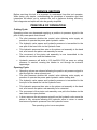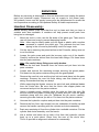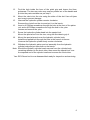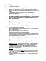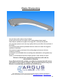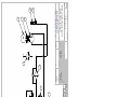
1
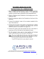
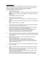
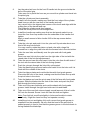
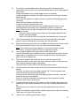
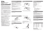
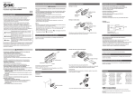
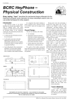
Beef Head/Loin Cutter
Model RC35
INSTRUCTION MANUAL
Imported by:
Licensed distributor
Designation:
Model No:
Specifications:
Air/Oil Intensifier
RC50
Type:
Height:
Width:
Depth:
Weight:
3410
570mm
500mm
227mm
35.33Kg
Hydraulic Circuit:
157Bar/2200Psi
Shell Helix ATF III or equivalent
6.5-7.85Bar/90-110Psi
Pneumatic Circuit:
Serial No:
Test Date:
Manufacture Date:
Manufactured By:
Argus Realcold Ltd
PO Box 12-519
9 Prescott Street, Penrose
Auckland, New Zealand
Ph
++64 9 526 5757
Fax ++64 9 526 5755
Supplied
TABLE OF CONTENTS
SAFETY INSTRUCTIONS
1
NOTICE TO OPERATORS
2
INSTRUCTIONS FOR COMMISSIONING
3
SERVICE SECTION
4
PRINCIPLE OF OPERATION:
Cutting Cycle:
Opening Cycle:
SERVICING:
Handtool Disassembly:
Servicing:
Reassembly:
4
4
4
5
5
7
9
APPENDIX 1
13
Parts List RC35-1113
Parts Diagram RC35-1113
Parts List RC35-1114
Parts Diagram RC35-1114
Order Form
14
15
16
17
18
APPENDIX 2
19
Maintenance:
Check Daily:
Check Weekly:
Routine Maintenance:
20
20
21
22
APPENDIX 3
23
Blade Sharpening
24
APPENDIX 4
25
Recommended Spare Parts
26
APPENDIX 5
27
Circuit Schematic
28
Argus Realcold Ltd, PO Box 12-519, 9 Prescott Street, Penrose, Auckland, New Zealand
Phone +64-9-526 5757, Fax +64-9-526 5755, Email : [email protected] , www.argus.co.nz
Issue Date: 17-2-2005
Revision Number: 2.0
Revision Date: 19-6-2006
SAFETY INSTRUCTIONS FOR REALCOLD HAND TOOLS
As a designer, manufacturer, and supplier of plant and equipment Argus
Realcold Ltd has provided plant, equipment, and all relevant information to
ensure the safe use in accordance with the New Zealand Health and Safety in
employment Act 1992.
The “CE” marked machines provided by Argus Realcold Ltd also meet the EC
machinery directive 98/37/EC and any other relevant EC directive. It is the
responsibility of the owner to ensure that the machine is used safely in
accordance with the instructions and for the purpose that the machine was
designed for.
The hand tools that we supply, with the exception of the RC33, are designed for
two-handed operation and include the following:
RC20
Sheep Light Duty Scissor
RC21
Sheep Hock Cutter
(Various blade options available)
RC22
Hydraulic Sheep Hock/Horn/Neck Cutter
RC25
Hydraulic Heavy Duty Sheep/Goat/Deer Hock/Horn Cutter
RC30
Hydraulic Beef Hock/Horn Cutter, Hog Head Cutter
(Various blade options available)
RC31
Pneumatic Sheep & Lamb Brisket Opener
RC33
Pneumatic Wool Shear
RC35
Hydraulic Beef Loin/Head Cutter
(Various blade options)
RC45
Hydraulic Heavy Duty Beef Horn Cutter
RC50
Air/Oil Intensifier
Argus Realcold Ltd, PO Box 12-519, 9 Prescott Street, Penrose, Auckland, New Zealand
Phone +64-9-526 5757, Fax +64-9-526 5755, Email : [email protected] , www.argus.co.nz
1
NOTICE TO OPERATORS, MAINTENANCE,
AND CLEAN-UP PERSONNEL
OPERATORS
Stop using a defective or malfunctioning tool immediately. Report the
problem or defect immediately to your supervisor for removal of tool from
service.
Do not attempt to make repairs yourself; do not tamper with a defective or
malfunctioning tool.
Do not attempt to free a jammed or blocked tool yourself.
Remove power from the tool when the tool is left unattended or is not in use.
Never tie-down, bypass, or alter the triggers or safety switches of the tool.
Wear safety glasses when operating this tool.
Do not activate switches of the tool unless you intend to operate and use the
tool.
Do not allow unauthorised individuals to operate the tool.
Never place fingers, hands, or other parts of your body in the cutting path of the
tool.
This tool is capable of causing severe injury or death if misused.
CLEAN-UP PERSONNEL
Shut off all power and disconnect all hydraulic and air hoses from the tool
before performing clean up.
Take extreme care near sharp blades.
MAINTENANCE PERSONNEL
Shut off all power and disconnect all hydraulic and air hoses from the tool
before making repairs, performing maintenance, and before replacing or
sharpening blades.
Do not use substitute parts or use other than genuine Argus Realcold brand
parts.
Use extreme care when testing or operating the tool.
Argus Realcold Ltd, PO Box 12-519, 9 Prescott Street, Penrose, Auckland, New Zealand
Phone +64-9-526 5757, Fax +64-9-526 5755, Email : [email protected] , www.argus.co.nz
2
RC35 BEEF HEAD/LOIN CUTTER
INSTRUCTIONS FOR COMMISSIONING
1. Mount a suitable spring balancer unit with a weight range from
30Kg to 40Kg near the operating station, in an appropriate
position to ensure ease of operation for the suspended tool.
2. Attach a Stainless steel D-shackle to the hanging eye on the
blade pivot bolt.
3. Attach the balancer cable to the D-shackle at the front of the
hand tool.
4. Connect the hydraulic hoses to the couplers supplied at the
rear of the hand tool.
5. Connect the air hoses to the airlines on the hand tool, making
sure that air pressure is supplied to the RED hoses, and the
GREEN hoses are connected to the signal line.
6. Connect the power pack and operate the tool a few times to
purge any air from the hand tool and hydraulic hoses.
7. Tie the hydraulic hoses and air lines together and arrange
them so that they are out of the way of the operator.
Note: The use of cable ties for this can cause the air lines to
pinch preventing the hand tool from operating correctly.
We recommend using electrical tape instead.
Your RC35 Hand tool is now ready for service.
Argus Realcold Ltd, PO Box 12-519, 9 Prescott Street, Penrose, Auckland, New Zealand
Phone +64-9-526 5757, Fax +64-9-526 5755, Email : [email protected] , www.argus.co.nz
3
SERVICE SECTION
Before servicing this tool it is important to understand how this tool operates.
While being very simple, understanding the principles of operation and their
interaction will assist you to maintain the tool to optimum working efficiency.
Fault diagnosis and repair will also be greatly simplified.
PRINCIPLE OF OPERATION:
Cutting Cycle:
Operating valves are depressed supplying a positive air pressure signal to the
pilot of the power pack control board.
•
The pilot pressure shuttles the control valve allowing main supply air
pressure to operate the power pack hydraulic valve.
•
The hydraulic valve opens and hydraulic pressure is transmitted to the
rear port of the hand tool via the hydraulic hose.
•
This hydraulic pressure then acts on the piston rod assembly in the hand
tool, and causes the piston rod assembly to move.
•
The movement of the piston rod assembly is now transmitted to the
blades via cam links and the blades close.
•
Hydraulic pressure will build to 150 bar/2200 PSI as soon as cutting
pressure is exerted, causing the blades to cut through the animal’s
appendage.
Opening Cycle:
•
Operating valves are released allowing the positive air pressure signal to
vent through the valve exhaust port.
•
The pilot pressure shuttles the control valve allowing main supply air
pressure to operate the power pack hydraulic valve closing side.
•
The hydraulic valve opens and hydraulic pressure is transmitted to the
front port of the hand tool via the hydraulic hose.
•
This hydraulic pressure then acts on the piston rod assembly in the hand
tool, and causes the piston rod assembly to be retracted.
•
The movement of the piston rod assembly now pulls the blades via the
cam links to the open position.
•
A timer removes the air pressure signal from the hydraulic valve once the
piston is fully retracted allowing the hydraulic valve to return to centre
and remove hydraulic pressure from the hydraulic hoses.
The operating cycle is now complete.
4
SERVICING:
Before any servicing is attempted on this tool disconnect and unplug the power
pack from electrical supply. Disconnect any air supply to the power pack.
All hydraulic hoses and air supply hoses must be disconnected to render the
tool inoperative according to Occupational Safety & Health requirements.
Handtool Disassembly:
Before starting please make sure that the tool is clean and that you have a
suitable work area available. A container will help prevent small parts from
being lost or damaged.
1.
Mount the tool in a vice; use the flat sides of the pistol grip. Take care to
use soft jaws and a rag to prevent damaging handle.
Note: Jaws may be easily made up from wood or plastic with a section
recessed to capture the pistol grip. This prevents the tool from
tipping in the vice and is particularly useful for larger tools.
2.
Cut the zip tie securing the paired airline to the D-handle, taking care not
to cut the airline.
3.
Loosen the grub screw and push the two-way valve out of the handle.
Carefully remove the airlines from the hose barb fittings. Put these items
into the parts container.
Note: Be careful, these fittings are easily broken.
4.
Remove the bolt and D-handle from the clevis and put them into the
parts container.
5.
Loosen and remove the remaining screws securing the guard plates.
Put these into the parts container along with the guard plates.
6.
Remove the cam link nuts and the pivot bolt nuts and place into the parts
container. Remove the cam link bolts taking care that blades do not
swing. Remember that they are sharp!
7.
While supporting the blades remove the pivot bolt and withdraw blades
from the clevis tube. Be sure that the clevis tube slipper plates are
recovered and put into the parts container.
8.
Using a suitable punch, carefully drive the yoke pin from the yoke. Be
sure to recover the plastic clevis plug for reuse and put it into the parts
container along with the yoke pin. Withdraw the pin punch carefully,
removing the cam links as you do so. Put them into the parts container.
9.
Unscrew the hydraulic couplers and put them into the parts container.
10.
Remove the four 6mm cap screws from the underside of handle cap and
remove the handle cap along with the cylinder and clevis assembly.
11.
Drain any remaining oil from the cylinder into a suitable container. Put the
cylinder and clevis assembly onto the bench.
12.
Use a scriber and steel rule to mark a line from the hydraulic cylinder
body up to a point about 15mm from the rear of the clevis tube.
This is to provide an alignment reference for reassembly.
5
13.
Find the hole inside the bore of the pistol grip and loosen the 6mm
grubscrew. The two-way valve may now be pushed out of the handle and
put into the parts container as per step 3.
14.
Mount the clevis into the vice using the sides of the slot. Use soft jaws
and a rag to prevent damage.
15.
Unscrew the hydraulic cylinder counter clockwise.
Remove the clevis from the vice and put it on the bench.
16.
Insert a #1 Phillips screwdriver through the hole at the front of the piston
rod, and a #3 Phillips screwdriver through the hole in the yoke.
Loosen and remove the yoke.
17.
Screw the hydraulic cylinder head into the special tool.
Mount the special tool into the vice, using the flat sides to grip it.
18.
Mount the special wrench over the hydraulic cylinder body.
Install the supplied bolt through the hole in the wrench to secure.
Unscrew the hydraulic cylinder body counter clockwise.
19.
Withdraw the hydraulic piston and rod assembly from the hydraulic
cylinder body and put them both on the bench.
Note: Should the hydraulic cylinder head unscrew from the cylinder body,
remaining attached to the clevis tube, then mount the special tool over
the exposed end of the cylinder head and unscrew the clevis tube.
Your RC35 hand tool is now disassembled ready for inspection and servicing.
6
Servicing:
1.
Clean all parts thoroughly.
2.
Visually inspect all parts for any signs of wear or damage.
3.
Blades: Look particularly for nicks in cutting edge. These will quickly
develop into cracks if left unattended, leading to dangerous failure of the
blade.
The blades may be touched up according to the maintenance
instructions in appendix 2.
If regrinding it is critical that the blade angles are maintained.
This will ensure that your blades maintain peak cutting efficiency.
Argus Realcold offers a blade sharpening service. You will find this
service to be very cost effective in maintaining your hand tool at
peak cutting efficiency.
4.
Seals may be easily removed by hooking them from their locating
grooves.
Take care not to damage the bronze piston and cylinder head.
The seals should be replaced each time the tool is serviced.
Use only genuine Argus Realcold seals for replacement.
These are available in a convenient seal kit:
Part number: 110-302105-A
5.
Cylinder Body: Inspect for damage.
Small nicks or scratches can be polished out with fine (240 grit or finer)
wet and dry sandpaper.
More severe damage will require replacement.
Be aware that even insignificant appearing damage will cut and damage
the piston seals, causing premature seal failure.
External damage may also be far from cosmetic. It can cause distortion
of the cylinder bore, which will damage seals and/or cause them to leak.
It may also damage the bronze piston.
6.
Piston Rod Assembly: Inspect for damage. Small nicks and scratches
may be polished out with fine (240 grit or finer) wet and dry sandpaper.
More severe damage will require replacement.
Be sure to keep the piston rod clean during service.
Be aware that even insignificant appearing damage will cut and damage
the cylinder head seals, causing premature seal failure.
7.
Pivot bolts and nuts: Inspect for damage or wear. If the pivot bolts are
noticeably grooved from operational wear, they should be replaced.
The Nylok blade pivot nut should not be reused more than once.
The nylon locking insert deforms and loses its ability to hold the nut
securely with repeated reuse.
8.
Cam links: Inspect for damage or wear. If the holes are elongated then
replace the cam links.
Check for wear by inserting a new pivot bolt and yoke pin into the hole.
They should be a sliding fit with minimal slop. If the hole is loose then
replace the cam link.
Check for straightness with a steel rule. If at all bent, then replace the
cam links.
7
9.
Yoke and Yoke Pin: Inspect for damage or wear.
If the holes are elongated then replace the yoke.
If the yoke pin is visibly worn or grooved then replace it.
Check for wear by inserting a new yoke pin into the holes.
It should be a sliding fit with no slop.
A little tight is ok.
If the holes are loose then replace the yoke and pin.
10.
Slipper plates: Inspect for damage or wear.
If the plates are noticeably worn or grooved then replace them.
11.
Two Way Valve:
Unscrew cover.
Withdraw valve spool and spring.
Remove O-rings from valve spool.
Clean all parts thoroughly.
Install new O-rings onto the valve spool.
Install spring into valve body.
Apply a little air tool oil to the O-rings on the valve spool and insert it
through the spring and into the valve body.
Reinstall the cover nut over the valve spool and tighten it onto the valve
body.
8
Reassembly:
Before starting, make sure that all parts are clean and free of oil and grease.
Make sure that the bore of the handle and cap assembly is clean free from
oxides. All replacement parts and/or serviced parts should be
procured/completed and ready to hand.
1.
Install New Piston Seals.
A piece of plastic strapping can assist to pull the seals into place over the
piston.
Make sure that the seals are located properly in their grooves and are
not twisted.
Apply a suitable lubricant to the seals.
2.
Install New Cylinder Head Seals.
Use a blunt instrument (not a screwdriver) to push the seal fully into its
groove.
Make sure that the seal is located properly in its groove. It should float a
little.
Apply a suitable lubricant to the seals.
3.
Take the piston and rod assembly with its new seal in place and push it
into the cylinder body with a twisting motion.
4.
Install the hydraulic cylinder head into the special tool, and mount the
tool into the vice again as you did during disassembly.
Carefully install the piston rod through the cylinder head and seals.
Screw the cylinder body onto the cylinder head and tighten.
Clean any excess grease from the front of the piston rod.
5.
Apply a small amount of blue Loctite 243 to the male threads of the yoke.
Turn the hydraulic cylinder over, install the yoke into the hydraulic piston
rod and tighten.
6.
Mount the clevis into the vice by its flat sides again and screw the
hydraulic cylinder onto it.
Mount the special wrench over the hydraulic cylinder body.
Install the supplied bolt through the hole in the wrench to secure.
Tighten the cylinder clockwise onto the clevis tube until the alignment
marks scribed earlier line up.
7.
Mount the handle in the vice as you did during disassembly, using rags
to prevent damage.
8.
Insert the paired air hose into the 9.0mm hole at the back of the pistol
grip.
Push the red hose onto hose barb marked “IN”. Push the green hose
onto the remaining unmarked hose barb.
Coat the brass valve body with food grade grease and push it into the
socket at the front of the handle.
Push it in until the retaining nut seats against the aluminium handle.
Secure with the 6mm grub screw from inside the bore of the handle.
9
9.
Lay the paired air hose for the front D-handle into the groove inside the
bore of the pistol grip.
Take care not to pinch the hose as you mount the cylinder and clevis into
the pistol grip.
10.
Take the cylinder and clevis assembly.
Install it into the handle, making sure that the front edge of the cylinder
head lines up with the rear face of the handle and cap.
Lay a steel rule in the slipper plate recess of the clevis and align with the
mating face of the handle and cap.
The hydraulic cylinder ports face upward.
Check the cover p hoto for correct alignment.
11.
Install the handle cap making sure that two dot punch marks line up.
Insert the four 6mm cap screws from the underside of the handle and
tighten.
Apply a small amount of blue Loctite 243 to the cap screws before
installing.
12.
Take the yoke pin and push it into the yoke until it protrudes about one
third of the way into the slot.
You may need to rotate the piston rod and yoke with a large flat
screwdriver to align the yoke hole with the access hole in the clevis tube.
13.
Take the cam links and liberally coat the yoke end with food grade
grease.
Insert one cam link into the yoke from the right side of the tool with the
raised side of the fork facing downward.
14.
Take the second cam link and insert it into the yoke from the left side of
the tool with the raised side of the fork facing upward.
15.
Push the yoke pin through the links fully until seated.
Take the plastic plug removed earlier and install it into the hole until it is
flush with the outside of the clevis.
16.
Take the slipper plates and coat both sides with food grade grease.
Place into the front of the clevis, making sure that the holes line up with
the pivot holes in the clevis.
17.
Take the blades and coat the pivot area of the flat face with food grade
grease. Slide the blades into the front of the clevis and push the pivot
bolt through the holes to secure.
18.
Take one of the cam link bolts and coat the shank with food grade
grease. Install through the right hand side cam link and blade.
19.
Take one of the cam link nuts and apply a small amount of blue Loctite
243 into the threads. Screw it onto the cam link bolt and tighten.
Note: Cam link bolt must float slightly in holes and be able to rotate
freely. If tight the hand tool may not operate correctly.
20.
Install the pivot nut and tighten fully until excess food grade grease is
expelled from the assembly. Be sure that the head of the pivot bolt is
seated properly in its slot, and that the grease groove in the bolt shank is
facing towards the blade tips.
10
21.
To achieve correct blade tension this step must be followed strictly.
Gradually loosen the pivot nut until the blades start to slide easily against
each other.
Grasp both blades from outside edge and move together.
A light resistance should be felt while moving, but no sticking or binding
should be felt.
Use a second spanner to tighten the jam nut while still holding the pivot
nut firmly.
Check that the blades still slide freely.
If it does not then loosen the jam nut.
Loosen the pivot nut a little at a time, retightening the pivot nut and
checking blade movement until a satisfactory tension is attained.
Note: If the pivot is too tight the blades will not open properly when the
tool is used.
If the pivot is too loose animal matter will be trapped between the
blades causing damage.
Also if too loose the pivot bolt will be overstressed and may break.
22.
Take the remaining cam link bolt and coat the shank with food grade
grease. Install it through the remaining cam link and blade.
23.
Take the remaining cam link nut and apply a small amount of blue Loctite
243 into the thread. Screw it onto the cam link bolt and tighten.
Note: Cam link bolt must float slightly in holes and be able to rotate
freely. If tight the hand tool may not operate correctly.
24.
Take the guard plates and screw them to the clevis tube.
Use the D-handle screw installed loose to locate the front hole of the top
plate while you install the 6mm screw through the hose clip and guard
plate, but do not tighten yet.
25.
Take the D–handle and install the 8mm screw through the hole.
Screw the handle to the top of the clevis with the socket for the two way
valve facing toward the right, and tighten.
Use a little blue Loctite 243 on the threads of the screws.
26.
Insert the paired air hose into the 9.0mm hole from the left side of the D–
handle.
Push the red hose onto hose barb marked “IN”. Push the green hose
onto the remaining unmarked hose barb.
Coat the brass valve body with food grade grease and push it into the
socket at the top of the handle.
Push it in until the retaining nut seats against the aluminium handle.
Secure it with a 6mm grub screw.
27.
Lay the paired air hose from the bottom of the D–handle flat against the
underside of the handle and secure it near the mounting base with a zip
tie.
Place the air hose under the hose clip and tighten the 6mm screw to
secure.
A pair of combination pliers will be useful to prevent the clip from rotating.
Take care not to pinch the air hose.
28.
Tighten the remaining guard plate screws.
11
29.
Apply a small amount of Loctite 569 hydraulic sealer to one of the
hydraulic elbows. Screw it into the rear port on the hydraulic cylinder.
Tighten it until elbow is pointing rearward, parallel with the centreline of
the hand tool.
Apply a small amount of Loctite 569 hydraulic sealer to the remaining
thread of the hydraulic elbow.
Take one of the male hydraulic couplers
Screw it onto the hydraulic elbow and tighten.
30.
Apply a small amount of Loctite 569 hydraulic sealer to the remaining
hydraulic elbow. Screw it into the front port of the hydraulic cylinder.
Tighten it until elbow is pointing to the right side of the tool and rearward.
Screw a female hydraulic coupler loosely onto the elbow, and tighten the
elbow until the hydraulic coupler nut just clears the rear hydraulic elbow.
Remove the female hydraulic coupler and apply a small amount of
Loctite 569 hydraulic sealer to the remaining thread of the hydraulic
elbow.
Screw the female hydraulic coupler back onto the hydraulic elbow and
tighten.
Check the parts container and bench for any missing parts now.
Your RC35 hand tool is now ready to be returned to service.
Reinstall as per installation instructions at the front of the manual and test for
correct operation.
12
Appendix 1
Appendix 1
Parts Diagram and Ordering Form
Argus Realcold Ltd, PO Box 12-519, 9 Prescott Street, Penrose, Auckland, New Zealand
Phone +64-9-526 5757, Fax +64-9-526 5755, Email : [email protected] , www.argus.co.nz
13
RC35 BEEF HEAD SCISSOR
RC35-1113
ITEM NO.
1
1.1
1.2
1.3
1.4
2
3
4
5
6
7
8
8.1
8.2
8.3
8.4
9
10
11
12
13
14
15
16
17
18
19
20
21
22
23
24
25
26
QTY.
1
1
1
1
1
1
2
1
1
2
1
1
1
4
1
2
1
1
1
1
2
2
2
1
2
4
2
2
2
1
2
1
1
2
PART N0.
110-302101-A
110-302102-A
110-302103-A
110-302104-A
110-302105-A
120-353001-A
120-353002-A
130-304101-A
130-304102-A
130-304103-A
140-355104-A
150-306101-A
150-306102-A
800-CSM620-304
150-306103-A
800-RP4X45-304
150-356104-A
160-357101-A
160-357102-A
160-357103-A
160-307104-A
160-307105-A
170-358101-A
180-134021902
180-AA90-0606
180-KQ2H04-00
180-QVV-M06
180-QVV-F06
190-209508-A
800-2-MP-4
800-BHM612-304
800-BHM812-304
800-BHM820-304
800-GSM66-304
DESCRIPTION
HYDRAULIC CYLINDER COMPLETE
HYDRAULIC CYLINDER BODY
HYDRAULIC CYLINDER HEAD
PISTON & ROD ASSY
HYDRAULIC CYLINDER SEAL KIT
CLEVIS TUBE
SLIPPER PLATE S/S
YOKE
YOKE PIN
CAM LINK
SCISSOR BLADE HEAD
PISTOL GRIP COMPLETE
PISTOL GRIP ONLY
CAP SCREW M6x20 304
HANGER RING ONLY
ROLL PIN M4x45 304
D-HANDLE
PIVOT BOLT
PIVOT NUT
PIVOT NUT
CAM BOLT
CAM NUT
SAFETY GUARD PLATE
TUBE CLIP
HYDRAULIC ELBOW MALE
STRAIGHT CONNECTOR 4mm
HYDRAULIC COUPLER MALE
HYDRAULIC COUPLER FEMALE
PILOT VALVE
4mm TWINLINE
M6x12 BUTTON HEAD SCREW 304
M8x12 BUTTON HEAD SCREW 304
M8x20 BUTTON HEAD SCREW 304
M6x6 GRUB SCREW
12
11
3
10
13
21
25
24
9
15
23
23
14
16
RC35 BEEF HEAD SCISSOR
RC35-1113
13
5
4
6
8
2
1.4 1.2
1.4
17
1.3
7
20
22
19
20
1.1
18
RC35 BEEF LOIN SCISSOR
RC35-1114
ITEM NO.
1
1.1
1.2
1.3
1.4
2
3
4
5
6
7
8
8.1
8.2
8.3
8.4
9
10
11
12
13
14
15
16
17
18
19
20
21
22
23
24
25
26
QTY.
1
1
1
1
1
1
2
1
1
2
1
1
1
4
1
2
1
1
1
1
2
2
2
1
2
4
2
2
2
1
2
1
1
2
PART N0.
110-302101-A
110-302102-A
110-302103-A
110-302104-A
110-302105-A
120-353001-A
120-353002-A
130-304101-A
130-304102-A
130-304103-A
140-355103-A
150-306101-A
150-306102-A
800-CSM620-304
150-306103-A
800-RP4X45-304
150-356104-A
160-357101-A
160-357102-A
160-357103-A
160-307104-A
160-307105-A
170-358101-A
180-134021902
180-AA90-0606
180-KQ2H04-00
180-QVV-M06
180-QVV-F06
190-209508-A
800-2-MP-4
800-BHM612-304
800-BHM812-304
800-BHM820-304
800-GSM66-304
DESCRIPTION
HYDRAULIC CYLINDER COMPLETE
HYDRAULIC CYLINDER BODY
HYDRAULIC CYLINDER HEAD
PISTON & ROD ASSY
HYDRAULIC CYLINDER SEAL KIT
CLEVIS TUBE
SLIPPER PLATE S/S
YOKE
YOKE PIN
CAM LINK
SCISSOR BLADE LOIN
PISTOL GRIP COMPLETE
PISTOL GRIP ONLY
CAP SCREW M6x20 304
HANGER RING ONLY
ROLL PIN M4x45 304
D-HANDLE
PIVOT BOLT
PIVOT NUT
PIVOT NUT
CAM BOLT
CAM NUT
SAFETY GUARD PLATE
TUBE CLIP
HYDRAULIC ELBOW MALE
STRAIGHT CONNECTOR 4mm
HYDRAULIC COUPLER MALE
HYDRAULIC COUPLER FEMALE
PILOT VALVE
4mm TWINLINE
M6x12 BUTTON HEAD SCREW 304
M8x12 BUTTON HEAD SCREW 304
M8x20 BUTTON HEAD SCREW 304
M6x6 GRUB SCREW
12
11
3
10
13
21
25
24
9
15
23
23
RC35 BEEF LOIN SCISSOR
RC35-1114
14
16
13
5
4
6
8
2
1.4 1.2
1.4
17
1.3
20
7
22
19
20
1.1
18
?
9 Prescott Street
PO Box 12-519
Penrose, Auckland
New Zealand
Ph 09 526 5757
Fax 09 526 5755
[email protected]
Order Number
Date
Tool
Serial Number
Customer Order Form
Name
Address
Phone
Contact Person
Qty
Part Number
Description
Shipping Instructions:
Ship to Address
Attention
Level of Urgency
Normal
Urgent
18
Appendix 2
Appendix 2
Maintenance
Argus Realcold Ltd, PO Box 12-519, 9 Prescott Street, Penrose, Auckland, New Zealand
Phone +64-9-526 5757, Fax +64-9-526 5755, Email : [email protected] , www.argus.co.nz
19
Maintenance:
Please read this section thoroughly and make sure that these maintenance
checks are carried out routinely as specified.
Adherence to this maintenance schedule will ensure that you enjoy long and
trouble free service from your hand tool.
Before any servicing is attempted on this tool, disconnect and unplug from air
supply. All hydraulic hoses and air supply hoses must be disconnected to
render the tool inoperative according to Occupational Safety & Health
requirement.
Check Daily:
1. Clean the hand tool thoroughly before inspecting.
2. Visually inspect the hand tool for any obvious damage to components,
and for loose components.
Anything that you find at this stage must be remedied immediately.
The hand tool may need to be removed from service to affect remedy.
3. Look for oil leaking past the front of the cylinder head seal.
If there is oil present then the cylinder head seal is bypassing and must
be replaced.
4. Check pivot bolt tension as per step 21 in the reassembly instructions.
One of the cam bolts will need to be removed to facilitate this.
Remove the other once the pivot bolt has been properly adjusted and
apply grease to the blades around the cam bolt holes and to the shank of
the cam bolts before reinstalling.
5. Apply food grade grease to lubrication points.
Use a small hand held grease gun to apply grease to the pivot bolt. Apply
until grease is expelled from between the blades.
6. Use a spray grease to apply grease to the yoke and yoke pin area.
7. Wipe off excess grease before returning the hand tool to service.
8. Check the oil level in the hydraulic power pack (where applicable).
It should be between ½ and ¾ of the way up the sight glass mounted on
the tank. Refill as necessary.
Check the oil for colour and cleanliness at the same time.
If the oil has a milky appearance then it is water contaminated and must
be changed immediately.
Refer to your power pack manual for instructions.
9. Reconnect the hand tool and check that all couplers and fittings are tight.
10. Reconnect the air supply and test for correct operation.
These checks are to be performed on a daily basis, or prior to the start of
each shift where more than one shift operates each day.
20
Check Weekly:
This maintenance is best performed in the workshop.
1. Remove the blades and cam links from the hand tool as per the
instructions for disassembly.
2. Thoroughly clean the clevis, cam links, blades, and wear plates.
The grease used for lubrication becomes dry and hard, building up a
layer of dried grease after repeated exposure to heat from the sterilising
process.
3. Visually inspect the hand tool for any obvious damage to components,
and for loose components.
Check all fasteners for tightness.
Anything that you find at this stage must be remedied immediately.
4. Check the yoke pin, cam links, and cam bolts for wear as per the
instructions for servicing.
If they are loose or obviously worn then replace them now.
5. Check the blades for sharpness or edge damage.
Should they be d ull or damaged then sharpen them as per the
sharpening instructions in appendix 3.
Sharpen both blades evenly.
6. Apply grease to the cam links and reassemble them to the tool as per the
instructions for reassembly.
7. Apply grease to the pivot faces of the blades and wear plates.
Reassemble them to the tool as per the instructions for reassembly.
Make sure to tension the pivot bolt correctly.
8. Wipe off excess grease before returning the hand tool to service.
9. Reconnect the hand tool and check that all couplers and fittings are tight.
10. Reconnect the air supply and test for correct operation.
These checks are to be performed on a weekly basis, or approximately
every 40 hours of service where more than one shift operates each day.
21
Routine Maintenance:
Except where daily or weekly checks require replacement of wear items, the
hand tool should be fully stripped and serviced once every six months.
Wear items that should be replaced at this six month service are:
•
•
•
•
•
•
•
•
110-302105-A
130-304103-A
130-304102-A
160-357101-A
160-357102-A
160-357103-A
160-307104-A
160-307105-A
Seal kit
Cam link
Yoke pin
Pivot bolt
Pivot bolt nut
Pivot bolt jam nut
Cam bolt
Cam nut
All other components should be assessed for serviceability at this time and
replaced as necessary, as per the servicing instructions in the service section of
this manual.
Other factors which may necessitate a full service prior to this six month interval
include but are not limited to:
•
•
•
•
Power pack oil found to be dirty
Power pack oil found to be water contaminated
Blades damaged (i.e., accidental cutting onto the gambol)
Other damage caused by dropping or striking of the tool
Following the discovery of any of these occurrences the hand tool must be
removed from service, stripped, and thoroughly assessed for damage.
22
Appendix 3
Appendix 3
Blade Sharpening
Argus Realcold Ltd, PO Box 12-519, 9 Prescott Street, Penrose, Auckland, New Zealand
Phone +64-9-526 5757, Fax +64-9-526 5755, Email : [email protected] , www.argus.co.nz
23
Blade Sharpening
Use a linisher with a belt of about 240grit.
Linish gently along the full length of the cutting edge primary angle.
Take care to maintain the angle of the edge (40°), and also the profile.
Use only light pressure as heat may rapidly build up and affect the hardness of
the blade.
It is recommended that the polished finish be restored to retain the hygiene
qualities of the blade.
Use a stone to apply a witness to the cutting edge and remove the burr
created by linishing.
If a linisher is not available then a sanding drum attached to a die-grinder may
be used.
Under no circumstance should an angle grinder or disc sander be used.
Failure to follow these sharpening instructions will void the
manufacturer’s warranty.
Argus Realcold Ltd offer a blade reconditioning service that will restore
your blades to the original condition, which you will find to be very cost
effective in maintaining your blades at peak efficiency.
Argus Realcold Ltd, PO Box 12-519, 9 Prescott Street, Penrose, Auckland, New Zealand
Phone +64-9-526 5757, Fax +64-9-526 5755, Email : [email protected] , www.argus.co.nz
24
Appendix 4
Appendix 4
Recommended Spare Parts
Argus Realcold Ltd, PO Box 12-519, 9 Prescott Street, Penrose, Auckland, New Zealand
Phone +64-9-526 5757, Fax +64-9-526 5755, Email : [email protected] , www.argus.co.nz
25
Recommended Spare Parts
The following is a list of spare parts that we recommend your engineering
department to keep in stock at all times.
Having these parts on hand will assist you to maintain your tool in good working
order, and ensure that you avoid down time while waiting for parts delivery
should your hand tool require repair.
This list is a minimum recommendation for parts to support one unit in the field.
Where more than one tool is in service, quantities held in stock should be
adjusted accordingly.
Qty
Part Number
Description
2
110-302105-A
HYDRAULIC CYLINDER SEAL KIT
2
120-303002-A
SLIPPER PLATE S/S
1
130-304101-A
YOKE
2
130-304102-A
YOKE PIN
4
130-304103-A
CAM LINK
2
140-355104-A
SCISSOR BLADE HEAD
2
160-357101-A
PIVOT BOLT
4
160-357102-A
PIVOT NUT
4
160-357103-A
PIVOT JAM NUT
4
160-307104-A
CAM BOLT
4
160-307105-A
CAM NUT
10
180-3X1.5-N70
VALVE O RING
4
180-KQ2H04-00
PNEUMATIC STRAIGHT
2
180-QVV-F06
COUPLING SCREW TYPE FEMALE
2
180-QVV-M06
COUPLING SCREW TYPE MALE
2
190-209508-B
PILOT VALVE
4
190-209602-A
PILOT VALVE COVER NUT
4
190-209603-A
VALVE SPRING
800-2-MP-4
HOSE
5m
Argus Realcold Ltd, PO Box 12-519, 9 Prescott Street, Penrose, Auckland, New Zealand
Phone +64-9-526 5757, Fax +64-9-526 5755, Email : [email protected] , www.argus.co.nz
26
Appendix 5
Appendix 5
Circuit Schematic
Argus Realcold Ltd, PO Box 12-519, 9 Prescott Street, Penrose, Auckland, New Zealand
Phone +64-9-526 5757, Fax +64-9-526 5755, Email : [email protected] , www.argus.co.nz
27
ITEM
1
2
3
4
5
6
7
8
9
10
11
12
13
14
15
15
1
6mm
A
B
5
T
4
8
6
COPYRIGHT: THIS DOCUMENT IS THE
PROPERTY OF ARGUS REALCOLD LTD
IT MUST NOT BE COPIED OR THE CONTENTS
PASSED ON TO ANY THIRD PARTY WITHOUT
THE WRITTEN CONSENT OF THE COMPANY
HYDRAULIC HOSE
12.7mm ID
21.0Mpa/3000Psi RATED
A
B
2
EB
P
EA
DESCRIPTION
OPERATING SWITCHES, 3/2 N/NP SPRING RETURN
LOGIC VALVE, "AND" FUNCTION 0.3sec
OPERATING VALVE 5/2 SPRING RETURN
PNEUMATIC TIMER
HYDRAULIC VALVE 5/2 OPEN CENTRE
PRESSURE RELIEF VALVE
RETURN FILTER
TEST POINT
FILLER/STRAINER/BREATHER
ELECTRIC MOTOR
DRIVE COUPLING
HYDRAULIC PUMP
SIGHT LEVEL/TEMP GUAGE
OVER TEMP SWITCH
HAND TOOL CYLINDER D/A HYDRAULIC
PNEUMATIC SUPPLY
6.7Bar/100Psi
3
Q.A
MFG
APPV'D
CHK'D
DRAWN
B EAST
M ROBINS
NAME
UNLESS OTHERWISE SPECIFIED:
DIMENSIONS ARE IN MILLIMETERS
SURFACE FINISH:
TOLERANCES:
LINEAR:
ANGULAR:
SIGNATURE
FINISH:
7
9
DATE
MATERIAL:
16-2-2005
16-2-2005
PART NO OLD
DEBUR AND
BREAK SHARP
EDGES
12
11
REVISION A
14
13
SCALE:1:1
SHEET 1 OF 1
RC22-CIRC
A3
CIRCUIT DIAGRAM
RC22, RC30, RC35, RC45
PART NO.
TITLE:
DO NOT SCALE DRAWING
M
10