1
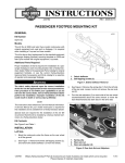
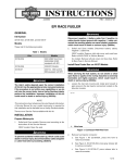
-J04530
REV. 2014-01-17
FOOTPEGS WITH WEAR TIP
Slipstream peg kits: On the following models ONLY, the wear
tip may be removed from Slipstream so the peg can be
mounted for passenger and/or highway peg use:
GENERAL
Kit Number
50039-10, 50500025, 50500030, 50500035, 50500262, 5069508, 50500441
Models
For model fitment information, see the P&A Retail Catalog or
the Parts and Accessories section of www.harley-davidson.com
(English only).
•
Sportster® models: 2004 and later models
•
Dyna® models: 2006 and later models
•
VRSC™ models: 2007 and later models
•
Softail® and Touring models: All models
•
Models with Highway Pegs: All models (does not fit with
Whiskers adjustable Highway Peg Bar Part Number:
50855-09, 50865-09).
1.
See Figure 2. Install footpeg to clevis and insert spring
washer (flat side toward clevis), clevis pin and retaining
ring. Wear tip must point down.
2.
If the footpeg is secured by a screw and nut, refer to the
appropriate service manual for torque specifications.
Installation Requirements
Loctite® 243 Threadlocker and Sealant - Blue (Part No. 9964297) to install replacement wear tips.
The rider's safety depends upon the correct installation
of this kit. Use the appropriate service manual procedures.
If the procedure is not within your capabilities or you do
not have the correct tools, have a Harley-Davidson dealer
perform the installation. Improper installation of this kit
could result in death or serious injury. (00333a)
Wear Tip Replacement
NOTE
Refer to the service manual for the wear tip orientation.
1.
Remove existing wear tip from footpeg.
This instruction sheet references service manual information.
A service manual for your model motorcycle is required for this
installation and is available from a Harley-Davidson Dealer.
2.
Apply 2 or 3 drops of Loctite 243 Threadlocker and Sealant
(Blue) to the threads of the new wear tip and install to the
footpeg.
Kit Contents
3.
For Kits 50039-10, 50695-08, 50500262: Tighten wear
tip to 6-9 ft-lbs (8.1-12.2 Nm).
NOTE
See Figure 3 and Table 1.
For Kits 50500025, 50500030, 50500035, 50500441:
Tighten wear tip to 14-16 ft-lbs (19.0-21.7 Nm).
REMOVAL
1.
See Figure 1. Remove retaining ring (5), spring washer
(4) and clevis pin to remove footpeg (1).
is03254a
INSTALLATION
2
5
4
Footrests must fold up and toward rear of motorcycle if
struck. Failure to set footrests to fold up and back could
result in death or serious injury. (00366a)
1
3
NOTE
Slipstream peg kits: Wear tip should face toward the rear of
the vehicle when installed (see last page for pictorials).
1.
2.
3.
4.
5.
Footpeg
Clevis
Clevis pin
Spring washer
Retaining ring
Figure 1. Footpeg Remove\Install (generic footpeg shown)
-J04530
Many Harley-Davidson® Parts & Accessories are made of plastics and metals which can be recycled.
Please dispose of materials responsibly.
1 of 2
is05203
Table 1. Service Parts
Item
1
Description (Quantity)
Part Number
Footpeg assembly, billet, right 50696-08
(For kit 50695-08)
Footpeg assembly, billet, right 50068-10
(For kit 50039-10)
Footpeg assembly, right (For Not Sold Separately
kit 50500025, 50500030,
50500035, 50500262,
50500441)
2
Footpeg assembly, billet, left 50750-08
(For kit 50695-08)
Footpeg assembly, billet, left 50097-10
(For kit 50039-10)
Footpeg assembly, left (For
kit 50500025, 50500030,
50500035, 50500262,
50500441)
Figure 2. Correct installation (generic footpeg and wear
tip)
3
Not Sold Separately
Wear tip (Buell part number) C0255.02A8
(Kit 50695-08 and 50500262
only)
Wear tip (Kit 50039-10 only) 50891-10
SERVICE PARTS
Wear tip (Kit 50500025 only) 50500022
is05202a
Wear tip (Kit 50500030 only) 50500023
1
Wear tip (Kit 50500035 only) 50500024
2
Wear tip (Kit 50500441 only) 50500438
4
Retaining ring, (Not
Shown)(Kits 50695-08,
50500030, 50500035)
11308
3
Figure 3. Service Parts: Footpegs and Wear Tip (Kit
50695-08 shown)
-J04530
2 of 2