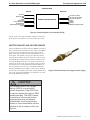
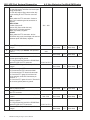
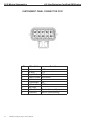
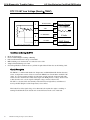
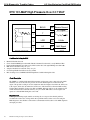
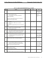
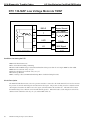
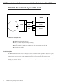
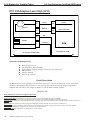
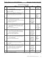
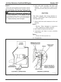
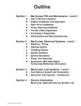
1
4.3 liter Emission Certified GM Engine
General Information–0A
SECTION 0A
GENERAL INFORMATION
IMPCO Technologies Engine Service Manual
1
0A–General Information
FUEL SYSTEMS CAUTIONS
4.3 liter Emission Certified GM Engine
•
Proper service and repair are important to the
safety of the service technician and the safe reliable operation of all engines. The service procedures recommended and described in this service manual are effective methods of performing
service and repair. Some of these procedures
require the use of tools specially designed for
the purpose.
If part replacement is necessary, the replacement
part must be of the same part number or equivalent part. Do not use a replacement part of
lesser quality. In the case of replacement parts
for the emission control system use only genuine
OEM replacement parts.
Before using a replacement part, service procedure, or a tool which is not recommended by the
engine manufacturer, it must first be determined
that neither personal safety nor the safe operation of the engine will be jeopardized by the
replacement part, service procedure or the tool
selected.
Special service tools shown in this service
manaual that have tool product numbers beginning with “J” or “BT” are available for world
wide distribution from:
o Kent-Moore Tools
o 28635 Mound Road
o Warren, MI. 48092
o 1-800-345-2233
CAUTION: Do not smoke, carry lighted tobacco, or
use a lighted flame of any type when working on or
near any fuel related component. Highly flammable
air-fuel mixtures may be present and can be ignited
causing personal injury.
CAUTION: Do not allow propane to contact the
skin. Propane is stored in the fuel tank as a liquid.
When propane contacts the atmosphere, it immediately expands into a gas, resulting in refrigeration
that can cause severe burns.
CAUTION: Do not allow propane to accumulate in
areas below ground level such as in a service pit
or underground ventilation systems. Propane is
heavier than air and can displace oxygen, creating a
dangerous condition.
It is important to note that this manual contains various
Warnings, Cautions and Notes that must be carefully observed in order to reduce the risk of personal injury during
service or repair. Improper service or repair may damage the
engine or render it unsafe or fail to make the engine emissions compliant. It is also important to warn of all hazardous
consequences that might result from careless treatment of the
engine. Failure to observe these items could influence terms
of the warranty.
!
WARNING
•
•
•
•
Special Tools which are required to service the
LPG fuel system are listed below
Failure to heed could result in death,
injury or property damage.
o
o
Hand held diagnostic scanner
ITK-1 Fuel pressure test kit
The tools are available from:
!
CAUTION
Less severe than WARNING, but has
the potential to cause injury or damage. Also used to notify of situations
that could lead to eventual failure,
injury or damage.
IMPORTANT: Denotes situations which could influence
safety or proper performance of the vehicle or component.
NOTICE: Significant item of information.
To reduce the chance of personal injury and/or property damage, the following instructions must be carefully observed.
2
IMPCO Technologies Engine Service Manual
IMPCO Engine System Division
7100 East 15 Mile Road
Sterling ‘Heights, MI. 48312
1-586-276-4333
ENGLISH AND METRIC FASTENERS
!
CAUTION
Late model engines use a combination
of English and Metric fasteners. The
components affected are the starter
motor, engine mounts, and flywheel
housing mounting. Other components
may also have a combination of fasteners, always verify that the proper
fasteners are used whenever removing
or replacing any components.
4.3 liter Emission Certified GM Engine
General Information–0A
Air Valve Vacuum (AVV): The vacuum signal taken from below the air valve assembly and above the throttle butterfly.
ADP: Adaptive Digital Processor.
Air/Fuel Ratio: The amount of air and fuel in the air fuel mixture, which enters the engine, shown in a ratio.
Analog Voltmeter: A meter that uses a needle to point to a value on a scale of numbers usually of the low impedance type; used
to measure voltage and resistance.
Aromatics: Pertaining to or containing the six-carbon ring characteristic of the benzene series. Found in many crude oils.
Backfire: Combustion of the air/fuel mixture in the intake or exhaust manifolds. A backfire can occur if the intake or exhaust
valves are open when there is a mis-timed ignition spark.
Benzene: An aromatic (C6H6). Sometimes blended with gasoline to improve antiknock value. Benzene is toxic and suspected of
causing cancer.
Bi-Fueled: A vehicle equipped to run on two fuels at the same time such as a fumigated diesel.
Blow-By: Gases formed by the combustion of fuel and air, which ordinarily should exert pressure only against the piston crown
and first compression ring. When rings do not seal, these gases (blowby) escape down the side of the piston into the crankcase.
BTU: British Thermal Unit. A measurement of the amount of heat required to raise the temperature of 1lb. of water 1 degree F.
Butane: An odorless, colorless gas, C4H10 found in natural gas and petroleum. One of the five LP gases.
CAFE: Corporate Average Fuel Economy.
CARB: California Air Resources Board.
Carbon Monoxide (CO): A chemical compound of a highly toxic gas that is both odorless and colorless.
Carburetor: An apparatus for supplying an internal-combustion engine a mixture of vaporized fuel and air.
Cathode Ray Tube: A vacuum tube in which cathode rays usually in the form of a slender beam are projected on a fluorescent
screen and produce a luminous spot.
Circuit: A path of conductors through which electricity flows before it returns to its source.
Closed Loop Operation: Applies to systems utilizing an oxygen sensor. In this mode of operation, the system uses oxygen sensor
information to determine air/fuel ratio. Adjustments are made accordingly and checked by comparing the new oxygen sensor to previous signals. No stored information is used.
CNG: Compressed Natural Gas.
CKP: Crankshaft Position Sensor
CMP: Camshaft Position Sensor
Conductor: A material, normally metallic, that permits easy passage of electricity.
Contaminants: Impurities or foreign material present in fuel.
Control Module: One of several names for a solid state microcomputer which monitors engine conditions and controls certain
engine functions; i.e. air/fuel ratio, injection and ignition time, etc.
Converter: A LPG fuel system component containing varying stages of fuel pressure regulation combined with a vaporizer.
Cryogen: A refrigerant used to obtain very low temperatures.
Current: The directed flow of electrons through a conductor. Measured in amps.
Dedicated Fuel System: A motor fuel system designed to operate on only one fuel type.
Diaphragm: A thin, flexible membrane that separates two chambers. When the pressure in one chamber is lower than in the
other chamber, the diaphragm will move toward the side with the low pressure.
Diaphragm Port: The external port located at the fuel inlet assembly and connected to the vacuum chamber above the air valve
diaphragm.
Digital Volt/Ohm Meter (DVOM): A meter that uses a numerical display in place of a gauge and is usually of the high impedance type.
DTC: Diagnostic Trouble Code
DST: Diagnostic Scan Tool.
DVOM: Digital volt/ohmmeter.
ECT: Engine Coolant Temperature.
ECM : Electronic Control module
IMPCO Technologies Engine Service Manual
3
0A–General Information
4.3 liter Emission Certified GM Engine
EFI: Electronic Fuel Injection. A fuel injection system, which uses a microcomputer to determine and control the amount of fuel,
required by, and injected into, a particular engine.
EGR: Exhaust gas recirculation.
EPA: Environmental Protection Agency: A regulating agency of the Federal government which, among other duties, establishes
and enforces automotive emissions standards.
Ethanol: Grain alcohol (C2H5OH), generally produced by fermenting starch or sugar crops.
Evaporative Emissions Controls: An automotive emission control system designed to reduce hydrocarbon emissions by trapping
evaporated fuel vapors from the fuel system.
Excess Flow Valve: A check valve that is caused to close by the fuel when the flow exceeds a predetermined rate.
FTV: Fuel Trim Valve.
FFV: Flexible Fuel Vehicle.
Firing Line: The portion of an oscilloscope pattern that represents the total amount of voltage being expended through the secondary circuit.
FMVSS: Federal Motor Vehicle Safety Standards.
FPP: Foot Pedal Position Sensor
Fuel Injector:, a spring loaded, electromagnetic valve which delivers fuel into the intake manifold, in response to electrical from
the control module.
Fuel Lock: A solenoid-controlled valve located in the fuel line to stop the flow when the engine stops or the ignition switch is
off.
Gasohol: 10 percent ethanol, 90 percent gasoline. Often referred to as E-10.
Gasoline: A motor vehicle fuel that is a complex blend of hydrocarbons and additives. Typical octane level is 89.
Greenhouse Effect: A scientific theory that suggests that excessive levels of carbon dioxide from the burning of fossil fuels is
causing the atmosphere to trap heat and cause global warming.
HD 10: A fuel of not less than 80% liquid volume propane and not more than 10% liquid volume propylene.
HD 5: A fuel of not less than 90% liquid volume propane and not more than 5% liquid volume propylene.
HDV: Heavy Duty Vehicle.
Hg: Chemical symbol for mercury. Used in reference to vacuum (in. of Hg).
Hydrocarbon: A chemical compound made up of hydrogen and carbon (HC). A major pollution emission of the internal combustion engine. Gasoline and almost all other fuels are hydrocarbons.
Hydrostatic Relief Valve: A pressure relief device installed in the liquid propane hose on a propane fuel system.
IAT: Intake Air Temperature
Ideal Mixture: The air/fuel ratio at which the best compromise of engine performance to exhaust emissions is obtained.
Typically 14.7:1.
Ignition Reserve: The difference between available voltage and the required voltage.
ILEV: Inherently Low Emission Vehicle.
IMPCO: Imperial Machine Products Company. IMPCO Technologies, Inc. A manufacturer of both LPG and Gasoline fuel systems.
Impedance: A form of opposition of AC current flow (resistance) measured in ohms.
Insulation: A nonconductive material used to cover wires in electrical circuits to prevent the leakage of electricity and to protect
the wire from corrosion.
Intercept: An electrical term for a type of splice where the original circuit is interrupted and redirected through another circuit.
ITK: IMPCO Test Kit
Knock: Sound produced when an engine’s air/fuel mixture is ignited by something other than the spark plug, such as a hot spot
in the combustion chamber. Can be caused by a
fuel with an octane rating that is too low or maladjusted ignition timing. Also called detonation or ping.
Lambda Sensor: A feedback device, usually located in the exhaust manifold, which detects the amount of oxygen present in exhaust gases in relation to the surrounding atmosphere.
LDV: Light Duty Vehicle.
4
IMPCO Technologies Engine Service Manual
4.3 liter Emission Certified GM Engine
General Information–0A
Lean Mixture: An air to fuel ratio above the stoichiometric ratio; too much air.
LEV: Low Emission Vehicle.
Limp-in or Limp-home: This term is used to describe the drivability characteristics of a failed computer system
Liquified Petroleum Gas (LPG): A fuel commonly known as propane consisting mostly of propane (C3H8), derived from the
liquid components of natural gas stripped out before the gas enters the pipeline, and the lightest hydrocarbons produced
during petroleum refining. Octane level is 107.
LPG: Liquified Petroleum Gas.
M85: A blend of gasoline and methanol consisting of 85% methanol and 15% gasoline.
Measurements of Pressure: 1 PSI=2.06 Hg (mercury) = 27.72” H2O (water column). At sea level atmospheric pressure is 29.92”
Hg.
Methanol: Known as wood alcohol (CH3OH), a light, volatile, flammable alcohol commonly made from natural gas.
Misfire: Failure of the air/fuel mixture to ignite during the power stroke.
Mixer: Fuel introduction device that does not include a throttle plate.
MPFI: Multi-Point Fuel injection. A fuel injection system that uses one injector per cylinder mounted on the engine to spray fuel
near the intake valve area of combustion chamber.
MTBE: Methyl Tertiary Butyl Ether. Oxygenate add to gasoline to reduce harmful emissions and to improve the octane rating.
Multi-fuel System: A motor fuel system designed to operate on two different fuels, such as LPG and gasoline.
Natural Gas: A gas formed naturally from buried organic material, composed of a mixture of hydrocarbons, with methane
(CH4) being the dominant component.
NGV: Natural Gas Vehicle.
Nox: See Oxides of Nitrogen.
Octane Rating: The measurement of the antiknock value of a motor fuel.
OEM: Original Equipment Manufacturer, the vehicle manufacturer.
Open-Loop: An operational mode during which control module memory information is used to determine air/fuel ratio, injection timing, etc., as opposed to actual oxygen sensor input.
Orifice: A port or passage with a calibrated opening designed to control or limit the amount of flow through it.
Oscilloscope: An instrument that converts voltage and frequency readings into traces on a-cathode ray tube (also see Cathode
Ray Tube).
Oxides of Nitrogen: Chemical compounds of nitrogen bonded to various amounts of oxygen (Nox). A chief smog forming-agent.
Oxygen Sensor: An automotive fuel system that produces a signal in accordance with the oxygen content of the exhaust gas.
(See Lambda Sensor).
Oxygenate: MTBE, ethanol and methanol. Oxygenates are added to gasoline to increase the oxygen content and therefore reduce
exhaust emissions.
Ozone: A radical oxygen module (O3) that is found in the upper atmosphere and filters out ultraviolet radiation from the sun.
Ground level ozone is formed by Nox, during the formation of photochemical smog.
Particulates: Microscopic pieces of solid or liquid substances such as lead and carbon that are discharged into the atmosphere by
internal combustion engines.
Positive Crankcase Ventilation (PCV): An automotive emission control system designed to reduce hydrocarbon emissions by
routing crankcase fumes into the intake manifold rather than to the atmosphere.
Pressure Differential: The differential between atmospheric pressure and intake manifold (referred to as vacuum) pressure.
Pressure Regulator: A device to control the pressure of fuel delivered to the fuel injector(s).
Primary Circuit: The low-voltage or input side of the ignition coil.
Propane: An odorless, colorless gas, C3H8, found in natural gas and petroleum.
PTV: Pressure Trim Valve
Reactivity: Refers to the tendency of an HC in the presence of Nox and sunlight to cause a smog-forming reaction. The lighter
the HC, the lower reactivity tends to be.
Regulator: An assembly used to reduce and control the pressure of a liquid or vapor.
Resistance: The opposition to the flow of current in an electrical circuit. Measured in ohms.
IMPCO Technologies Engine Service Manual
5
0A–General Information
4.3 liter Emission Certified GM Engine
Rest Pressure: Fuel pressure maintained within the system after engine shutdown.
Rich Mixture: An air to fuel ratio below the stoichiometric ratio; too much fuel.
SAE: Society of Automotive Engineers.
Secondary Circuit: The high-voltage output side of the ignition coil.
SEFI or SFI: Sequential Electronic Fuel Injection or Sequential Fuel Injection.
Sensors: Devices that provide the control module with engine information as needed to properly control engine function.
Spark Line: The portion of an oscilloscope pattern that represents the time during which the air/fuel mixture is being burned in
the combustion chamber.
Splice: An electrical term for the joining of two or more conductors at a single point.
Stoichiometric Ratio: An ideal fuel/air ratio for combustion in which all of the fuel and most of the oxygen will be burned.
Sulfur Oxides: Chemical compounds where sulfur is bonded to varying numbers of oxygens, produced by the combustion of
gasoline or any other fuel that contains sulfur. As sulfur oxides decompose in the atmosphere, they combine with water to
form sulfuric acid.
System Pressure: The fuel pressure maintained in the system during normal engine operation.
Tap: An electrical term for a type of splice where the original circuit is not interrupted.
TBI: Throttle Body Injection. Any of several injection systems that have the fuel injector(s) mounted in a centrally located throttle body.
Throttle Body: Controls engine RPM by adjusting the engine manifold vacuum to the mixer. Consists of housing shaft, throttle
liner and butterfly valve.
TLEV: Transitional Low Emission Vehicle.
TMAP: Combined Air Inlet and Manifold Pressure Sensor.
Toluene: A liquid aromatic hydrocarbon C7H8.
TPS: Throttle Position Sensor.
ULEV: Ultra Low Emission Vehicle.
Vaporization: A process in which liquid changes states into gas.
Venturi Air Valve Vacuum (VAVV): An amplified air valve vacuum signal coming from the venturi area of the mixer, directly
exposed to airflow before the addition of vaporized LPG.
Volt/Ohmmeter (VOM): A combination meter used to measure voltage and resistance in an electrical circuit. Available in both
analog and digital types. May be referred to as AVOM and DVOM.
Voltage: The electrical pressure that causes current to flow in a circuit. Measured in volts.
Voltage Drop: A lowering of the voltage in a circuit when resistance or electrical load is added.
Xylene: C6H4 (CH3)2. Any of three toxic flammable oily isomeric aromatic hydrocarbons that are dimethyl homologues of benzene and are usually obtained from petroleum or natural gas distillates.
ZEV: Zero Emission Vehicle.
6
IMPCO Technologies Engine Service Manual
4.3 liter Emission Certified GM Engine
Maintenance–OB
SECTION OB
MAINTENANCE
IMPCO Technologies Engine Service Manual
1
OB–Maintenance
4.3 liter Emission Certified GM Engine
MAINTENANCE
V-BELT SYSTEMS
The maintenance of the engine and its related components is
critical to the life of the engine and optimum performance
during its useful life. All engines require a certain amount of
maintenance. The suggested maintenance requirements are
contained in this section. Industrial engines operate in various environments from extremely dusty environments, to hot
and cold temperature environments and clean environments.
The recommended schedule is a recommended guide line for
the owner and servicing agency to follow, however certain environmental operating conditions may require more frequent
inspection and maintenance. In addition the owner may have
installed additional equipment to the equipment which may
also increase the requirements for service on certain components. Therefore the owner and servicing agent should review
the operating condition of the equipment and determine if
more frequent inspections and maintenance cycles maybe
required.
Check the belt tension by pressing down on the midway point
of the longest stretch between two pulleys. The belt should
not depress beyond 13mm (1/2 inch). If the depression is
more than allowable adjust the tension. Do not over tighten
the tension of the belt. Over tightening may cause overload
on the bearings and pulleys of the drive belt components.
!
WARNING
When performing maintenance on the
engine, shut off the engine and disconnect the battery negative cable to
avoid injury or damage to the engine.
The engine installed in this equipment may use one or both
accessory drive belt configurations. The drive belt may be
incorporated to drive the water pump, alternator and addition
pumps or devices. It is important to note, the drive belt is an
integral part of the cooling and charging system and should
be inspected at a minimum according to the maintenance
schedule in this section and in extremely hot and dirty environments more often.
When inspecting the belts check for:
•
Cracks,
•
Chunking of the belt,
•
Splits
•
Material hanging loose from the belt
•
Glazing, hardening
If any of these conditions exist the belt should be replaced
with an OEM replacement belt.
2
IMPCO Technologies Engine Service Manual
!
WARNING
Alcohol or Methanol base antifreeze or
plain water are not recommended for
use in the cooling system at anytime.
SERPENTINE BELT SYSTEM
Serpentine belts utilize a spring-loaded tensioner which keeps
the belt properly adjusted. Serpentine belts should be checked
according to the maintenance schedule in this section.
IMPORTANT:
The engine manufacturer does not recommend the use of
“belt dressing” or “anti slipping agents” on either belt configuration.
COOLING SYSTEM
It is important to remember that the cooling system of this
engine be maintained properly to insure the longevity of the
engine. Maintenance of the cooling system is critical to not
only the engine but the fuel system as well. Because the LPG
vaporizer is connected into the cooling system low coolant
levels and restricted or plugged radiator cores can impact the
performance of the fuel system. Therefore proper maintenance of the cooling system should include removing dust,
dirt and debris from the radiator core on regular intervals. To
properly maintain the cooling system follow the recommend
maintenance schedule in this section.
Cooling system inspections should be performed as prescribed when inspecting the cooling system check for the following:
•
Plugged or restricted radiator core clean with compressed air, blow dust and debris from the core and
the fan shroud
•
Check the radiator cap to insure proper sealing if
damage replace
4.3 liter Emission Certified GM Engine
•
!
Check for coolant leaks at the radiator tank seams
WARNING
Do not remove the cooling system
pressure cap when the engine is hot.
Allow the engine to cool and then remove the cap slowly allowing pressure
to vent. Hot coolant under pressure
may discharge violently
Maintenance–OB
ENGINE ELECTRICAL SYSTEM
MAINTENANCE
The engine electrical system incorporates computers to control certain functions of the equipment. The electrical system
connections and ground circuits require good connections.
Follow the recommended maintenance schedule in this section to maintain optimum performance. When inspecting
the electrical system check the following:
•
Check battery connection clean and insure that
connectors are tight.
•
Check battery for cracks or damage to the case
replace if necessary.
•
Check Positive and Negative cables for corrosion,
rubbing, chaffing and insure tight connections at
both ends.
•
Check engine wire harness for rubbing, chaffing,
pinching, and cracks or breaks in the wiring.
•
Check engine harness connectors, check to
insure fitted and locked by pushing the connector
together then pull on the connector halves to
insure they are locked.
•
Check ignition coil wire for hardening, cracking,
arcing, chaffing, separation, split boot covers and
proper fit.
•
Check spark plug wires for hardening, cracking,
chaffing, separation, split boot covers and proper
fit.
•
Replace spark plugs at the required intervals per
the recommended maintenance schedule
IMPORTANT:
•
The engine manufacturer and the fuel system supplier do not
recommend the use of “stop leak” additives to repair leaks in
the cooling system. If leaks are present the radiator should be
removed and repaired.
Check to insure all electrical components are
securely mounted and retained to the engine or
chassis.
•
Check to insure any additional electrical devices
installed by the owner are properly installed in the
system.
•
Check the MIL, charging, and oil pressure lights
for operation by starting the engine and checking
that the light illuminates for the prescribe period
of time before turning out.
and inlet joints repair or replace as necessary
•
Check for leaks at the radiator hose connections,
tighten hose clamps if necessary
•
Check Radiator hoses for swelling, separation,
cracks deterioration in the hoses, or hardening, if
any of these conditions exist the hose should be
replaced with the OEM replacement parts
•
Check coolant level if low add with 50/50 mixture,
Do not add plain water
•
Replace coolant per the recommended schedule at
the end of this section
Checking the Coolant Level
1. Check coolant level in coolant recovery tank. Add
specified coolant as required.
If the radiator requires repair insure that the radiator core
repairs did not result in a significant reduction in the cooling
capacity of the radiator.
The engine manufacturer recommends the cooling system
be filled with a 50/50 mixture of ethelyene glychol anitfreeze
and water.
This GM industrial engine can utilize any type of permanent
antifreeze or any brand antifreeze solution that meets GM
Specification 1825M or 1899M which will not damage aluminum parts.
IMPCO Technologies Engine Service Manual
3
OB–Maintenance
ENGINE CRANKCASE OIL
OIL RECOMMENDATION
Prior to changing the oil, select oil based on the prevailing
daytime temperature in the area in which the equipment will
be operated. The chart in figure 1 is a guide to selecting the
proper crankcase oil.
IMPORTANT:
Oils containing “solid” additives, non-detergent oils, or low
quality oils are not recommended by the engine manufacturer.
4.3 liter Emission Certified GM Engine
CHECKING/FILLING ENGINE OIL LEVEL
!
CAUTION
Overfilled crankcase (oil level being to
high) can cause an oil leak, a flucuation or drop in the oil pressure and
rocker arm “clatter” on engines. The
overfill condition results in the engine
crankshaft splashing and agitating
the oil, causing it to foam (become
aereated). The aereated oil causes the
hydraulic lifters to “bleed down”. This
results in rocker arm clatter and loss of
engine performance due to valves not
opening properly.
IMPORTANT;
Care must be taken when checking engine oil level. Oil
level must be maintained between the “ADD” mark and the
“FULL” mark on the dipstick. To ensure that you are not getting a false reading, make sure the following steps are taken
before checking the oil level.
Figure 1 Engine Oil Viscosity Recommendation
USE OF SUPPLEMENTAL ADDITIVES
Use of the oils recommended by the engine manufacturer
already contains a balanced additive treatment. The uses of
supplemental additives which are added to the engine oil by
the customer are not necessary and may be harmful. The
engine manufacturer, fuels system suppliers and engine distributors do not review, approve or recommend such products.
SYNTHETIC OILS
Synthetic oils have been available for use in industrial engines for a relatively long period of time. Synthetic oils may
offer advantages in cold temperature pumpability and high
temperature oxidations resistance. However, synthetic oils
have not proven to provide operational or economic benefits
over conventional petroleum-based oils in industrial engines.
Their use does not permit the extension of oil change intervals.
4
IMPCO Technologies Engine Service Manual
1. Stop engine if in use
2. Allow sufficient time (approximately 5 minutes) for the
oil to drain back into the oil pan
3. Remove the dipstick. Wipe with a clean cloth or paper
towel and reinstall. Push the dipstick all the way into the
dipstick tube.
4. Remove the dipstick and note the oil level.
5. Oil level must be between the “FULL” and “ADD”
marks.
4.3 liter Emission Certified GM Engine
Maintenance–OB
6. Check sealing ring on drain plug for any damage, replace
if necessary, wipe plug with clean rag, wipe pan sealing
surface with clean rag and re-install plug into the pan.
Tighten to specification.
7. Fill crankcase with oil.
8. Start engine and check for oil leaks.
9. Dispose of oil and filter in a safe manner.
Figure 2 Engine Oil Dip stick (Typical)
6. If the oil level is below the “ADD” mark, proceed to Step
7 and 8, and reinstall the dipstick into the dipstick tube.
7. Remove the oil filler cap from the valve rocker arm cover
8. Add the required amount of oil to bring the level up to but
not over the “FULL” mark on the dipstick
FUEL SYSTEM INSPECTION AND
MAINTENANCE
PROPANE FUEL SYSTEM
The Propane fuel system installed on this industrial engine
has been designed to meet the emission standard applicable
for this equipment for 2004 model year. To ensure compliance to these standards follow the recommended maintenance
schedule contained in this section.
9. Reinstall the oil filler cap to the valve rocker arm cover
and wipe any excess oil clean.\
INSPECTION AND MAINTENANCE OF THE
FUEL STORAGE CYLINDER
CHANGING THE ENGINE OIL
IMPORTANT:
When changing the oil, always change the oil filter.
1. Start the engine and run until it reaches normal operating
temperature.
IMPORTANT:
Change oil when engine is warm from operation as it flows
more freely, carrying away more impurities.
2. Stop engine.
IMPORTANT:
Engine oil will be hot. Use protective gloves to prevent burns.
Engine oil contains chemicals which may be harmful to your
health avoid skin contact.
The fuel storage cylinder should be inspected daily or at the
beginning of each operational shift for any leaks, external
damage, adequate fuel supply and to insure the manual service valve is open. Fuel storage cylinders should always be
securely mounted, inspect the securing straps or retaining
devices for damage insure that all locking devices are closed
and locked. Check to insure that the fuel storage cylinder is
positioned with the locating pin in the tank collar on all horizontally mounted cylinders this will insure the proper function of the cylinder relief valve.
When refueling or exchanging the fuel cylinder check the
quick fill valve for thread damage. Insure the o-ring is in
place, check the o-ring for cracking, chunking or separation,
replace if damaged before filling. Check the service line
quick coupler for any thread damage. Insure the o-ring is in
place, check the o-ring for cracking, hardening, chunking or
separation. Replace if damaged.
IMPORTANT:
3. Remove drain plug and allow the oil to drain.
4. Remove and discard oil filter and it sealing ring.
5. Coat sealing ring on the new filter with clean engine oil,
wipe the sealing surface on the filter mounting surface to
remove any dust, dirt or debris. Tighten filter securely
(follow filter manufacturers instructions). Do not overtighten.
When refueling the fuel cylinder, wipe clean both the female
and male connection with a clean rag prior to filling. This
will prevent dust, dirt and debris from being introduced to the
fuel cylinder and prolong the life of the fuel filter.
IMPCO Technologies Engine Service Manual
5
OB–Maintenance
INSPECTION AND REPLACEMENT OF THE
FUEL FILTER
The Propane system on this emission certified engine utilizes
an in-line replaceable fuel filter element. This element should
be replaced, at the intervals specified in the recommended
maintenance schedule. When inspecting the fuel filter check
the following:
• Check for leaks at the inlet and outlet fittings, using a
soapy solution or an electronic leak detector, if leaks are
detected make repairs
• Check to make sure filter is securely mounted.
• Check filter housing for external damage or distortion, if
damaged replace fuel filter
To replace the filter use the following steps:
1. Move the equipment to a well ventilated area and insure
all external ignition sources are not present.
2. Start the engine.
3. With the engine running close the manual valve.
4. When the engine runs out of fuel turn OFF the key when
the engine stops and disconnect the battery negative cable.
IMPORTANT:
A small amount of fuel may still be present in the fuel line,
use gloves to prevent burns, wear proper eye protection. If
liquid fuels continues to flow from the connections when
loosened check to make sure the manual valve is fully closed.
5. Slowly loosen the inlet fitting and disconnect.
6. Slowly loosen the outlet fitting and disconnect.
7. Remove the filter housing form the equipment.
IMPORTANT: The fuel cylinder manual valve contains
an “Excess Flow Check Valve” open the manual valve
slowly to prevent activating the “Excess Flow Check
Valve”.
15. Check for leaks at the inlet and outlet fittings, and the
filter housing end connection using a soapy solution or an
electronic leak detector, if leaks are detected make repairs.
LOW PRESSURE REGULATOR
MAINTENANCE AND INSPECTION
IMPORTANT:
The Low Pressure Regulator (LPR) components have been
specifically designed and calibrated to meet the fuel system
requirements of the emission certified engine. The regulator
should not be disassembled or rebuilt. If the LPR fails to operate or develops a leak the LPR should be replaced with the
OEM recommended replacement parts.
When inspecting the regulator check for the following items:
• Check for any fuel leaks at the inlet and outlet fittings.
• Check for any fuel leaks in the regulator body.
• Check the inlet and outlet fittings of the coolant supply
lines for water leaks.
• Check the coolant supply lines for hardening, cracking,
chaffing or splits. If any of these conditions exist replace
coolant lines.
• Check coolant supply hose clamp connections, ensure
they are tight.
8. Check for contamination.
• Check the to ensure the Pressure Trim Valve (PTV)
mounting bolts are secure.
9. Tap the opening of the filter on a clean cloth.
• Check PTV for external damage.
10. Check for debris.
11. Check canister for proper mounting direction.
12. Reinstall the filter housing to the equipment.
13. Tighten the inlet and outlet fittings to specification.
14. Open the manual valve.
6
4.3 liter Emission Certified GM Engine
IMPCO Technologies Engine Service Manual
• Check PTV electrical connection to ensure the connector
is seated and locked.
• Check to ensure the regulator is securely mounted.
4.3 liter Emission Certified GM Engine
CHECKING/DRAINING OIL BUILD-UP IN
THE LOW PRESSURE REGULATOR
During the course of normal operation oil or “heavy ends”
may build inside the secondary chamber of the Low Pressure
Regulator (LPR). These oil and heavy ends may be a result
of poor fuel quality, contamination of the fuel supply chain,
or regional variation of the fuel make up. If the build up
of oil becomes significant this can affect the performance
of the secondary diaphragm response. The Recommended
Maintenance Schedule found in this section recommends that
the oil be drained periodically.
IMPORTANT:
Draining the regulator when the engine is warm will help the
oils to flow freely from the regulator.
To drain the LPR use the following steps:
1. Move the equipment to a well ventilated area and ensure
no external ignition sources are present.
Maintenance–OB
13. Remove the receptacle and reinstall the LPR with the two
retaining bolts and tighten to specifications.
14. Reinstall the outlet fitting and secure with the previously
removed locking pin.
15. Reconnect the PTV electrical connection push connector
until lock “Click”, pull on the connector to ensure it is
locked, connect the vacuum line.
16. Reconnect the outlet hose and secure the hose clamp.
17. Reinstall the fuel inlet line and tighten connection to
specification.
18. Slowly open the manual service valve.
IMPORTANT:
The fuel cylinder manual valve contains an “Excess Flow
Check Valve” open the manual valve slowly to prevent activating the “Excess Flow Check Valve”.
2. Start the engine.
19. Check for leaks at the inlet and outlet fittings using a
soapy solution or an electronic leak detector, if leaks are
detected make repairs. Check coolant line connections to
ensure no leaks are present.
3. With the engine running close the manual valve.
20. Start engine recheck for leaks at the regulator.
4. When the engine runs out of fuel turn OFF the key when
the engine stops and disconnect the battery negative cable.
21. Dispose of any drained material in safe and proper manner.
IMPORTANT:
A small amount of fuel may still be present in the fuel line,
use gloves to prevent burns, wear proper eye protection. If
liquid fuels continues to flow from the connections when
loosened check to make sure the manual valve is fully closed.
AIR FUEL MIXER/THROTTLE
CONTROL DEVICE MAINTENANCE
AND INSPECTION
IMPORTANT:
5. Slowly loosen the inlet fitting and disconnect.
6. Loosen the hose clamp at the outlet hose fitting and
remove the hose.
7. Remove and retain the locking pin in the outlet fitting and
remove the outlet fitting from the LPR
8. Disconnect PTV connection and disconnect the vacuum
hose.
9. Remove the two LPR mounting bolts and retain.
The Air Fuel Mixer components have been specifically designed and calibrated to meet the fuel system requirements of
the emission certified engine. The mixer should not be disassembled or rebuilt. If the mixer fails to operate or develops
a leak the mixer should be replaced with the OEM recommended replacement parts.
When inspecting the mixer check for the following items:
• Check for any fuel leaks at the inlet fitting.
10. Place a small receptacle in the engine compartment.
• Check the fuel inlet hose for cracking, splitting or chaffing, replace if any of these condition exist.
11. Rotate the LPR to 90° so that the outlet fitting is pointing
down into the receptacle and drain the LPR.
• Check to ensure the mixer is securely mounted.
12. Inspect the secondary chamber for any large dried
particles and remove.
• Check air inlet hose connection and insure clamp is tight,
check inlet hose for cracking, splitting or chaffing, replace if any of these condition exist.
IMPCO Technologies Engine Service Manual
7
OB–Maintenance
• Check air cleaner element according to the
Recommended Maintenance Schedule found in this section.
• Check fuel line to Throttle body mounted Fuel Trim
Valve (FTV) for cracking, splitting or chaffing, replace if
any of these condition exist.
• Check Throttle body return action to ensure throttle shaft
is not sticking repair if necessary.
• Check FTV electrical connection to ensure connector is
fully seated and locked.
• Check for leaks at the throttle body and intake manifold.
• Check Throttle cable for damage, rubbing, and kinking
and free movement repair if necessary.
EXHAUST SYSTEM AND CATALYTIC
CONVERTER INSPECTION AND
MAINTENANCE
IMPORTANT:
The exhaust system on this emission certified engine contains
an Exhaust Gas Oxygen Sensor (EGO) which provides feed
back to the ECM on the amount of oxygen present in the exhaust stream after combustion. The measurement of oxygen
in the exhaust stream is measured in voltage and sent to the
ECM. The ECM then makes corrections to the fuel air ratio
to ensure the proper fuel charge and optimum catalytic performance. Therefore it is important that the exhaust connections remain secured and air tight.
IMPORTANT:
The EGO sensor is sensitive to silicone or silicone based
products. Do not use silicone sprays or hoses which are assembled using silicone lubricants. Silicone contamination can
cause severe damage to the EGO.
When inspecting the Exhaust system check the following:
• Check the exhaust manifold at the cylinder head for leaks
and that all retain bolts and shields (if used) are in place.
• Check the manifold to exhaust pipe fasteners to ensure
they are tight and that there are no exhaust leaks repair if
necessary.
• Check EGO electrical connector to ensure connector
is seated and locked, check wires to ensure there is no
cracking, splits chaffing or “burn through” repair if necessary.
8
IMPCO Technologies Engine Service Manual
4.3 liter Emission Certified GM Engine
• Check any exhaust pipe extension connector for leaks
tighten if necessary
• Visually inspect converter to insure muffler is securely
mounted and tail pipe is properly aimed.
• Check for any leaks at the inlet and outlet of the converter
4.3 liter Emission Certified GM Engine
Maintenance–OB
CERTIFIED ENGINE MAINTENANCE REQUIREMENTS
Install
Date
General Maintenance Section
Visual check for leaks
Check engine oil level
Check coolant level
Change engine oil and filter
Check Fuel system for leaks
Inspect Accessory Drive belts
Inspect electrical system
Inspect all vacuum lines and fitting
Inspect all fuel lines and fitting
Engine Coolant Section
Check coolant level
Clean debris from radiator core
Change coolant
Inspect coolant hoses for cracks,
swelling or deterioration
Engine Ignition System
Inspect Battery case for damage
Inspect battery cables
Check all electrical connectors
Check ignition timing and adjust
Replace spark plugs
Check spark plug wires
Fuel System Maintenance
Replace fuel filter
Inspect lock off for leaks
Ensure lock off closing
Test LPG/Gas regulator pressure
Inspect LPR for oil build up
Inspect LPR for coolant leaks
Check air induction system for leaks
Check manifold for vacuum leaks
Check FTV electrical connection
Check throttle shaft for sticking
Check injector & rails for leaks
Inspect air cleaner
Replace filter element
Engine Exhaust System
Inspect exhaust manifold for leaks
Inspect exhaust piping for leaks
Inspect catalyst inlet and outlet
Check HEGO sensor connector
Daily
250
500
Interval Hours
750 1000 1250
1500
1750
2000
X
X
X
Every 100 hours or 60 days of operation
Prior to any service or maintenance activity
X
X
X
X
X
X
Every 100 hours or 60 days of operation
X
X
X
X
X
X
X
X
X
X
X
X
X
X
X
X
X
X
Annually or every 2000 hours
Annually or every 2000 hours
X
X
X
X
X
Every 200 hours, or every 100 hours in dusty environment
Annually, or Bi-annually in dusty environments
X
X
X
X
The maintenance schedule represents manufacturers recommended maintenance intervals to maintain
proper engine/equipment function. Specific state and federal regulations may require equipment operators
to conduct comprehensive engine/equipment inspections at more periodic intervals than those specified
above. This maintenance schedule has no regulatory value and should not be considered representative
of any state or federal engine/equipment maintenance requirement.
IMPCO Technologies Engine Service Manual
9
OB–Maintenance
10
IMPCO Technologies Engine Service Manual
4.3 liter Emission Certified GM Engine
4.3 liter Emission Certified GM Engine
Fuel System Operation–1A1
SECTION 1A1
LPG FUEL SYSTEM OPERATION
IMPCO Technologies Engine Service Manual
1
1A1–Fuel System Operation
4.3 liter Emission Certified GM Engine
IMPCO SPECTRUM LPG FUEL SYSTEM
Tank Pressure
Fuel Cylinder
Regulated Pressure
Mil
Light
Intake Air
Fuel Filter
Air/Fuel Mixture
Exhaust Gas
Electric
Lockoff
Low
Pressure
PTV Regulator
Air Cleaner
Engine Control Module
Mixer
TPS
TMAP
Throttle Body
Speed control
motor
FTV
FPP
ENGINE
ECT
Distributor
(Timing)
Oil Pressure
Crankshaft
Sensor
o2
Catalytic Muffler
Figure 1 Typical Fuel System Schematic
2
IMPCO Technologies Engine Service Manual
4.3 liter Emission Certified GM Engine
DESCRIPTION AND OPERATION OF
THE FUEL SYSTEMS
PROPANE FUEL SYSTEM
The primary components of the propane fuel system are the
fuel storage tank, low pressure regulator (LPR), fuel mixer
module with throttle control device, electric fuel lock-off solenoid, engine control module (ECM) fuel trim valve (FTV)
pressure trim valve (PTV) and Three Way Catalytic (TWC)
converter. The system operates at pressures which range from
355.60 mm (14.0 inches) of water column up to 21.5 BAR (312
psi). Figure 1 Typical Fuel System Schematic.
Fuel System Operation–1A1
SERVICE LINE
Propane flows from the fuel tank to the electric lock via the
service line. The service line is connected to the tank utilizing a quick coupler. The other end of the service line is connected to a “bulkhead connector” mounted on the equipment
sheet metal. This bulkhead connector allows for a safe means
of passing through the equipments engine compartment sheet
metal and into the engine compartment. If a bulkhead connector is used a pressure relief device is mounted in the service line or the connector itself to prevent over pressurization
of the service line. The service line is made of high pressure
hose with special material or possibly tubing which is compatible with the LPG fuel and should always be replaced with
an OEM supplied part.
!
LPG FUEL TANK
Propane is stored in the fuel tank as a liquid. The approximate pressure of the fuel in the tank is 16.5 bar (240 psi)
when the tank is full at an ambient temperature of 27° C
(81°F). The boiling point, (temperature at which the liquid
fuel becomes vapor) is approximately -40° C (-40° F). When
the fuel changes from liquid to vapor the fuel expands and
creates pressure inside the tank. When the tank service valve
is opened the pressure inside the tank forces the liquid fuel
out though the pick up tube located near the bottom of the
fuel cylinder. Because the Propane is stored under pressure
the tank is equipped with a safety valves which are normally
set at 25.8 bar (375 psi) to prevent tank rupture due to overpressurization of the cylinder. The service valve mounted in
the end of the cylinder controls the flow of fuel from the tank.
By turning the handle to its “open” position, fuel flows out of
the tank and into the service line. The service valve is also
equipped with a safety feature called an “excess flow check
valve”. This feature reduces the flow from the service valve
in the event of a rupture of the fuel line or any down stream
1. Liquid Outage valve w/quick
disconnect coupling
11. Vapor Withdrawal Tube
(when applicable)
2. Filler Valve
12. 80% Limitor Tube
3. Pressure Relief Valve
13. Fuel Level Float
4. Liquid Outage Fill Check Valve
14. Liquid Withdrawal Tube
CAUTION
The bulkhead assembly should never
be removed and a service line run
throught the sheet metal.
FUEL FILTER
Propane fuel like all other motor fuels is subject to contamination from outside sources. Refueling of the equipments
tank and removal of the tank from the equipment can inadvertently introduce dirt and other foreign matter into the fuel
system. It is therefore necessary to filter the fuel prior to
entering the fuel system components down stream of the tank.
An inline fuel filter has been installed in the fuel system to
remove the dirt and foreign matter from the fuel. The inline
filter is replaceable as a unit only. Maintenance of the filter
is critical to proper operation of the fuel system and should be
replaced as defined in the Maintenance Schedule, SECTION
0B. In severe operating condition more frequent replacement
of the filter may be necessary.
Fuel Flow
5. Fuel Gauge
Figure 3 Inline Fuel Filter
ELECTRIC LOCK OFF
component.
Figure 2 Typical Propane Cylinders
The Electric Lock Off device is an integrated assembly. The
electric lock assembly is a 12 volt normally closed valve. The
solenoid is mounted to the valve body. When energized the
solenoid opens the valve and allows the Propane fuel to flow
through the device. The valve opens during cranking and run
IMPCO Technologies Engine Service Manual
3
1A1–Fuel System Operation
4.3 liter Emission Certified GM Engine
cycles of the engine. The lock off supply voltage is controlled
by the engine control module (ECM).
is to regulate a specific amount of venture vacuum to the atmospheric side of the secondary diaphragm. By introducing
vacuum to the top side of the secondary diaphragm during
regulator operation the amount of fuel being delivered to the
mixer can be “trimmed” or reduced to allow for correction
to the air fuel ratio for closed loop fuel control. The solenoid
receives a reference signal from the ECM which causes the
solenoid to be pulsed fast or slow depending on the amount of
fuel to be trimmed.
!
CAUTION
The LPR is an emission control device. Components inside the regulator are specifically calibrated to meet
the engine emissions requirements
and should never be disassembled or
rebuilt. If the LPR fails to operate, replace with an OEM replacement part.
Figure 4 Electric Fuel Lock Off
LOW PRESSURE REGUALTOR (LPR)
The LPR is a combination vaporizer, pressure regulating device. The LPR is a negative pressure two stage regulator that
is normally closed when the engine is not running. When the
engine is cranking or running a partial vacuum is created in
the fuel line which connects the regulator to the mixer. This
partial vacuum opens the regulator permitting fuel to flow to
the mixer.
Propane fuel enters the primary port of the LPR and passes
through the primary jet and into the primary/exchanger chamber. As the propane passes through the heat exchanger the
fuel expands and creates pressure inside the chamber. The
pressure rises as the fuel expands when the pressure rises
above 10.34 kpa (3.5 psi), sufficient pressure is exerted on the
primary diaphragm to cause the diaphragm plate to pivot and
press against the primary valve pin thus closing off the flow
of fuel. This action causes the flow of fuel into the regulator to be regulated. When the engine is cranking, sufficient
vacuum will be introduce into the secondary chamber from
the mixer drawing the secondary diaphragm down onto the
spring loaded lever and opening the secondary valve allowing vaporized fuel to pass to the mixer. Increased vacuum in
the secondary chamber increases the downward action on the
secondary lever causing it to open wider allowing more fuel
to flow to the mixer.
The regulator utilized on this emission certified engine is
equipped with a unique Pressure Trim Valve (PTV) which
is directly mounted to the regulator. This solenoid is a 12
volt normally closed solenoid. The function of this solenoid
4
IMPCO Technologies Engine Service Manual
Figure 5 Low pressure regulator
AIR FUEL MIXER
The air valve mixer is an air-fuel metering device and is
completely self-contained. The mixer is an air valve design,
utilizing a relatively constant pressure drop to draw fuel into
the mixer from cranking to full load. The mixer is mounted
in the air stream ahead of the throttle control device.
When the engine begins to crank it draws in air with the air
valve covering the inlet, negative pressure begins to build.
This negative pressure signal is communicated to the top of
the air valve chamber through 4 vacuum ports in the air valve
4.3 liter Emission Certified GM Engine
assembly. A pressure/force imbalance begins to build across
the air valve diaphragm between the air valve vacuum chamber and the atmospheric pressure below the diaphragm. The
air valve vacuum spring is calibrated to generate from 101.6
mm (4.0 inches) of water column at start to as high as 355.60
mm (14.0 inches) of water column at full throttle. The vacuum being created is referred to as Air Valve Vacuum (AVV).
As the air valve vacuum reaches 101.6mm (4.0 inches) of
water column, the air valve begins to lift against the air valve
spring. The amount of AVV generated is a direct result of the
throttle position. At low engine speed the air valve vacuum
is low and the air valve position is low thus creating a small
venturi for the fuel to flow. As the engine speed increases the
AVV increases and the air valve is lifted higher thus creating
a much larger venturi. This air valve vacuum is communicated from the mixer venturi to the LPR secondary chamber
via the low pressure fuel supply hose. As the AVV increases
in the secondary chamber the secondary diaphragm is drawn
further down forcing the secondary valve lever to open wider.
Fuel System Operation–1A1
Figure 6 Air Fuel Mixer
The mixer is equipped with a low speed mixture adjustment
which is retained in a tamper proof housing. The mixer has
been preset at the factory and should not require any adjustment. In the event that the idle adjustment should need to
be adjusted refer to the Fuel System Repair section of this
manual.
!
CAUTION
The air/fuel mixer is an emission
control device. Components inside
the mixer are specifically calibrated to
meet the engines emissions requirements and should never be disassembled or rebuilt. If the mixer fails to
operate replace with an OEM replacement part.
Figure 7 Pressure Trim Valve and Fuel Trim Valve
THROTTLE CONTROL DEVICE
Drive By Cable
Engine speed control is maintained by the amount of pressure
applied to a foot pedal located in the operator’s compartment.
A cable is utilized to connect the foot pedal to the throttle
shaft in the engine compartment. A coil spring mounted to
the pedal and the throttle shaft will keep the throttle shaft
in a “normally closed” position. When the foot pedal is depressed the throttle shaft is rotated opening the “butterfly” in
the venturi of the throttle body allowing more air and fuel to
enter the engine. When the ECM detects that the engine has
reached maximum governed speed or requires adjustment for
load, the ECM will correct the throttle plate position by overIMPCO Technologies Engine Service Manual
5
1A1–Fuel System Operation
riding the throttle shaft with the electronic governor.
The air fuel mixer is attached to the throttle control device
or “throttle body assembly” which is then connected to the
intake manifold of the engine. The Throttle body maintains
control of engine speed by increasing or decreasing the opening angle of the throttle blade in the throttle body bore thus
increasing or decreasing the fuel air mixture to the engine.
The throttle blade shaft is connected to a spring loaded cable
connector which is connected to the foot pedal in the operator’s compartment. The shaft incorporates a return spring
to insure the blade position returns to idle when the operator
removes his foot from the pedal. Also attached to the throttle
shaft is a Throttle Position Sensor (TPS), which provides
a signal to the ECM to indicate the throttle blade angle for
speed control and load control as well as emission control. On
the end opposite the TPS is the Foot Pedal Position (FPP) sensor which operates the foot pedal override command.
4.3 liter Emission Certified GM Engine
THREE WAY CATALYTIC MUFFLER
The emission certified engine has been designed and calibrated to meet the emission standards in effect for 2004. To help
meet the emission requirements the vehicle has been equipped
with a Three Way Catalytic (TWC) muffler. The catalyst
muffler is a three way catalyst, sound damping and spark arresting unit. Besides controlling the noise created from the
combustion process, and preventing sparks from escaping
from the exhaust system the most important function is treating the exhaust gases which are created from the combustion
process. The three-way catalyst consists of a honeycomb
coated with a mixture of platinum, palladium, and rhodium.
The hot gases flow through the catalyst sections where an oxidation and reduction reactions take place. These chemical reactions reduce the amount of CO, HC and NOX in the engines
exhaust. The exhaust gas then flows through the outlet.
Also mounted to the throttle control device is an integrated
electronic governor. The throttle control is maintained by a
foot pedal located in the operator’s compartment and connected to the throttle control device by a cable. The governor
is controlled by the ECM and has no external adjustments.
When the ECM determines load adjustment or maximum engine speed has been achieved the governor overrides the foot
pedal and corrects the throttle plate position.
Also mounted on throttle body assembly is the Fuel Trim
Valve (FTV). The FTV is a 12 volt normally closed solenoid
valve. During closed loop operation the ECM sends a pulse
signal to the FTV to open to allow more or less fuel to be
introduced below the throttle blade to correct the air fuel mixture for proper emission control.
Foot Pedal Position
Sensor
Throttle Position
Sensor
Figure 9 Three way catalytic converter
ENGINE CONTROL MODULE
Governor Motor
Figure 8 Throttle control device “LPG Drive by cable
throttle body assembly”
6
IMPCO Technologies Engine Service Manual
To obtain maximum effect from the catalyst and accurate
control of the air fuel ratio the emission certified engine
is equipped with an onboard computer or Engine Control
Module (ECM). The ECM is a 32 bit controller which receives input data from sensors fitted to the engine and fuel
system and then outputs various signals to control engine
operation.
One specific function of the controller is to maintain “closed
loop fuel control”. Closed loop fuel control is accomplished
when the Heated Exhaust Gas Oxygen sensor (HEGO)
mounted in the exhaust system sends a voltage signal to the
controller. The controller then calculates any correction that
may need to be made to the air fuel ratio. The controller then
outputs signals to PTV or the FTV or both mounted in the
fuel system to change the amount of fuel being delivered from
the regulator or mixer or to the engine.
4.3 liter Emission Certified GM Engine
Fuel System Operation–1A1
LPG ECM
INPUTS
O2 Sensor
Throttle Position
RPM
Timing
Oil Pressure
Coolant Temperature
Air Temperature
Manifold Absolute Pressure
Battery
OUTPUTS
Pressure Trim Valve
Fuel Trim Valve
Electric Lockoff Valve
Governor Speed Control
Timing
Ignition
Gauges
Malfunction Indicator Lamp
ENGINE CONTROL MODULE
Figure 10 LPG Engine control module (ECM)
The controller also performs diagnostic functions on the fuel
system and notifies the operator of engine malfunctions by
turning on a Malfunction Indicator Light (MIL) mounted
in the dash. Malfunctions in the system are identified by a
Diagnostic Trouble Code number. In addition to notifying the
operator of the malfunction in the system the controller also
stores the information about the malfunction in its memory.
A technician can than utilize a computerized diagnostic scan
tool to retrieve the stored diagnostic code and by using the
diagnostic charts in this manual determine the cause of the
malfunction. In the event a technician does not have the
computerized diagnostic tool, the MIL light can be used to
identify the diagnostic code. By following specific steps
the technician can activate the “blink” feature and count the
number of blinks to determine the diagnostic code number to
locate the fault in the system.
!
CAUTION
The Heated Exhaust Gas Oxygen
Sensor (HEGO) is an emissions
control component. If the HEGO fails
to operate, replace only with an OEM
replacement part. The HEGO sensor
is sensitive to silicone and silicone
based products and can become
contaminated. Avoid using silicone
sealers or hoses treated with silicone
lubricant in the air stream or fuel supply lines.
HEATED EXHAUST GAS OXYGEN SENSOR
The Heated Exhaust Gas Oxygen Sensor (HEGO) is mounted
in the exhaust system downstream of the engine. The HEGO
is used to measure the amount of oxygen present in the exhaust stream and communicate that to the ECM via an electrical signal. The amount of oxygen present in the exhaust
stream indicates whether the fuel air ratio is to rich or to lean.
If the HEGO sensor signal indicates that the exhaust stream
is to rich the ECM will decrease or lean the fuel mixture during engine operation, if the mixture is to lean the ECM will
richen the mixture. The ECM continuously monitors the
HEGO sensor output if a rich or lean condition is present for
an extended period of time and the ECM cannot correct the
condition the ECM will set a diagnostic code and turn on the
MIL light in the dash.
Figure 11 Heated Exhaust Gas Oxygen Sensor
(HEGO)
IMPCO Technologies Engine Service Manual
7
1A1–Fuel System Operation
4.3 liter Emission Certified GM Engine
ENGINE
"Input"
Exhaust
Gas Oxygen
Sensor
(HEGO) to
ECM
"Output"
PTV OR
FTV pulses
increases or
decreases
fuel delivery
to the
engine
ECM Calaculates
the change and
commands PTV
OR FTV signals
to increase or
decrease
Figure 12 Propane Closed Loop Control Schematic
8
IMPCO Technologies Engine Service Manual
4.3 liter Emission Certified GM Engine
Fuel System Operation–1A2
SECTION 1A2
GASOLINE FUEL SYSTEM OPERATION
IMPCO Technologies Engine Service Manual
1
1A2–Fuel System Operation
4.3 liter Emission Certified GM Engine
IMPCO 4.3 LITER MPFI FUEL SYSTEM
AIR FUEL MIXTURE
Fuel Tank
FRESH AIR
EXHAUST GASES
Mil
Light
GASOLINE RETURN
Gasoline
Fuel Pump
GASOLINE FUEL PRESSURE
GASOLINE FUEL PUMP PRESSURE
Fuel Filter
Engine Control
Module
Pressure
Regulator
Air
Induction
Air Cleaner
TPS
TMAP
Throttle Body
FPP
Speed
control motor
Manifold
Injector
(MPFI) System
ECT
Sensor
ENGINE
Distributor
(Timing)
Crankshaft
Sensor (RPM)
Oil Pressure
HEGO
Catalytic
Muffler
Figure 1 Gasoline Multi-Port Fuel Injection System
2
IMPCO Technologies Engine Service Manual
4.3 liter Emission Certified GM Engine
GASOLINE MULTI POINT FUEL INJECTION
SYSTEM (MPFI)
The primary components of the Gasoline Multi Point Fuel
Injection (MPFI) fuel system are the gasoline fuel tank, electric fuel pump, fuel filter, fuel rails, fuel pressure regulator,
fuel injector, O2 sensor, engine control unit and three way
catalytic muffler.
GASOLINE FUEL STORAGE TANK
Fuel System Operation–1A2
FUEL RAIL AND PRESSURE REGULATOR
The fuel flows from the fuel filter to the fuel rails where the
fuel is regulated. During engine operation the regulator
maintains the proper amount of fuel pressure to the top of the
injector. During lower RPM operation excess fuel at the top
of the injector is bypassed and returned to the fuel tank for
recirculation.
The Fuel pressure regulator has no adjustments and is integrated into the fuel rail assembly. The fuel rail also contains
a Schrader valve which is utilized to test the regulated pressure of the fuel system.
The gasoline fuel storage tank location may very on equipment applications. The fuel tank may be integrated into the
chassis frame or may be a stand alone vessel mounted on the
equipment. For precise location for the equipment application
refer to the OEMs vehicle manual.
GASOLINE FUEL PUMP
The Gasoline is stored as a liquid in the fuel tank and is
drawn into the fuel system by a 12 volt electric fuel pump.
Depending on the vehicle application the fuel pump may be
mounted in the fuel tank or as a stand alone component. In
either case the fuel pump will receive a signal from the ECM
at Key On to prime the fuel system for approximately 2 seconds prior to start. Priming of the fuel system provides for a
quicker start, when the engine begins to crank.
!
CAUTION
The fuel pump is an emissions control component. If the fuel pump fails
to operate, replace only with an OEM
replacement part. The fuel pump is
calibrated to supply the correct amount
of fuel to the injectors. Replacing the
pump with anything other than the
OEM replacement could cause damage to the fuel system and or damage
to the fuel tank.
FUEL FILTER
After the fuel is drawn into the fuel pump the fuel then flows
through the gasoline fuel filter. The fuel filter will trap small
particles as the fuel passes through the filter to remove debris
and prevent injectors from becoming damaged. Maintenance
of the fuel filter is required as indicated in the Recommended
Maintenance Schedule. A more frequent replacement of the
filter may be required if the equipment operates in a dusty or
dirty environment.
Pressure Test Port
Pressure
Regulator
Fuel Rail Assy
Figure 2 Gasoline Fuel Rail Assembly
FUEL INJECTOR
The fuel supply is maintained on the top of the injector by
the fuel pressure regulator. The injector is fed a “pulse”
signal through the wire harness which causes the injector to
open. During regular operating conditions the ECM controls
the opening and duration of opening of the injector. During
lower RPM operation the injector signals or “pulses” are less
frequent then when the engine is operating at higher RPMs.
The certified engine has been calibrated to deliver the precise
amount of fuel for optimum performance and emission control.
THROTTLE CONTROL DEVICE
Drive By Cable
Engine speed control is maintained by the amount of pressure
applied to a foot pedal located in the operator’s compartment.
A cable is utilized to connect the foot pedal to the throttle
shaft in the engine compartment. A coil spring mounted to
the pedal and the throttle shaft will keep the throttle shaft in a
“normally closed” position. When the foot pedal is depressed
the throttle shaft is rotated opening the “butterfly” in the venturi of the throttle body allowing more air to enter the engine.
When the ECM detects that the engine has reached maximum
governed speed or requires adjustment for load, the ECM will
correct the “blade position by overriding the throttle shaft
with the electronic governor.
IMPCO Technologies Engine Service Manual
3
1A2–Fuel System Operation
4.3 liter Emission Certified GM Engine
The Throttle Control device or “throttle body assembly” is
connected to the intake manifold of the engine. The Throttle
body maintains control of engine speed by increasing or decreasing the opening angle of the throttle blade in the throttle
body bore thus increasing or decreasing the intake air to the
engine. The throttle blade shaft is connected to a spring
loaded cable connector which is connected to the foot pedal in
the operator’s compartment. The shaft incorporates a return
spring to insure the blade position returns to idle when the
operator removes his foot from the pedal. Also attached to
the throttle shaft is a Throttle Position Sensor (TPS), which
provides a signal to the ECM to indicate the throttle blade
angle for speed control and load control as well as emission
control. At the opposite end of the throttle shaft (cable end) is
the Foot Pedal Position (FPP) sensor which indicates the position of the throttle pedal.
flow through the catalyst sections where an oxidation and reduction reactions take place. These chemical reactions reduce
the amount of CO, HC and NOX in the engines exhaust. The
Exhaust gas then flows through the outlet.
Also mounted to the throttle control device is an integrated
electronic governor. The throttle control is maintained by a
foot pedal located in the operator’s compartment and connected to the throttle control device by a cable. The governor
is controlled by the ECM and has no external adjustments.
When the ECM determines load adjustment or maximum
engine speed has been achieved the governor overrides the
throttle shaft and corrects the throttle blade position.
Figure 4 Three Way Catalytic Converter
Foot Pedal Position
Sensor
Throttle Position
Sensor
Governor Motor
Figure 3 Throttle Control Device “Drive By Cable
Throttle Body Assembly”
THREE WAY CATALYTIC MUFFLER
The emission certified engine has been designed and calibrated to meet the emission standards in effect for 2004. To help
meet the emission requirements the vehicle has been equipped
with a three way catalytic muffler. The catalyst muffler is
a three way catalyst, sound damping and spark arresting
unit. Besides controlling the noise created from the combustion process, and preventing sparks from escaping from the
exhaust system the most important function is treating the
exhaust gases which are created from the combustion process.
The three-way catalyst consists of a honeycomb coated with a
mixture of platinum, palladium, and rhodium. The hot gases
4
IMPCO Technologies Engine Service Manual
ENGINE CONTROL UNIT
To obtain maximum effect from the catalyst and accurate
control of the air fuel ratio the emission certified engine is
equipped with an onboard computer or Engine Control Unit
(ECM). The ECM is a 32 bit controller which receives in-put
data from sensors fitted to the engine and fuel system and
then out-puts various signals to control engine operation.
One specific function of the controller is to maintain “closed
loop fuel control”. Closed loop fuel control is accomplished
when the exhaust gas oxygen sensor (EGO) mounted in the
exhaust system sends a voltage signal to the controller. The
controller then calculates any correction that may need to be
made to the air fuel ratio. The controller then changes the
amount of fuel being delivered to the engine by changing the
pulse frequency to the injector. The controller also performs
diagnostic functions on the fuel system and notifies the operator of malfunctions by turning on a Malfunction Indicator
Light (MIL) mounted in the dash. Malfunctions in the system
are identified by a Diagnostic Code number. In addition to
notifying the operator of the malfunction in the system the
controller also stores the information about the malfunction in
its memory. A technician can than utilize a computerized diagnostic tool to retrieve the stored diagnostic code and by using the diagnostic charts in this manual determine the cause
of the malfunction. In the event a technician does not have
the computerized diagnostic tool the MIL light can be used to
identify the diagnostic code.
By following specific steps the technician can activate the
4.3 liter Emission Certified GM Engine
Fuel System Operation–1A2
GASOLINE ECM
INPUTS
O2 Sensor
Throttle Position
RPM
Timing
Oil Pressure
Coolant Temperature
Air Temperature
Manifold Absolute Pressure
Battery
OUTPUTS
Gasoline Fuel Pump
Governor Speed Control
Gasoline Fuel Injector
Timing
Ignition
Gauges
Malfunction Indicator Lamp
ENGINE CONTROL MODULE
Figure 5 Gasoline Engine Control Module (ECM)
“blink” feature and count the number of blinks to determine
the diagnostic code number to locate the fault in the system.
HEATED EXHAUST GAS OXYGEN SENSOR
The Heated Exhaust Gas Oxygen Sensor (HEGO) is mounted
in the exhaust system downstream of the engine. The HEGO
is used to measure the amount of oxygen present in the exhaust stream and communicate that to the ECM via an electrical signal. The amount of oxygen present in the exhaust
stream indicates whether the fuel air ratio is to rich or to lean.
If the HEGO sensor signal indicates that the exhaust stream
is to rich the ECM will decrease or lean the fuel mixture by
reducing the signals to the injectors during engine operation,
if the mixture is to lean the ECM will richen the mixture or
increase the pulse to the injectors. The ECM continuously
monitors the HEGO sensor output if a rich or lean condition
is present for an extended period of time and the ECM cannot
correct the condition the ECM will set a diagnostic code and
turn on the MIL light in the dash.
!
Figure 6 Heated Exhaust Gas Oxygen Sensor (Hego)
CAUTION
The Heated Exhaust Gas Oxygen
Sensor (HEGO) is an emissions
control component. If the HEGO fails
to operate, replace only with an OEM
replacement part. The HEGO sensor
is sensitive to silicone and silicone
based products and can become
contaminated. Avoid using silicone
sealers or hoses treated with silicone
lubricant in the air stream or fuel supply lines.
IMPCO Technologies Engine Service Manual
5
1A2–Fuel System Operation
4.3 liter Emission Certified GM Engine
ENGINE
"Output"
Injector
pulse
increases or
decreases
fuel delivery
to the
engine
"Input"
Heated
Exhaust
Gas Oxygen
Sensor
(HEGO) to
ECM
ECM Calculates
the change and
commands
injector signal to
increase or
decrease
Figure 7 Gasoline Closed Loop Control Schematic
6
IMPCO Technologies Engine Service Manual
4.3 liter Emission Certified GM Engine
LPG Fuel System Diagnostics–1B1
SECTION 1B1
LPG SYSTEM DIAGNOSIS
IMPCO Technologies Engine Service Manual
1
1B1–LPG Fuel System Diagnostics
4.3 liter Emission Certified GM Engine
LPG Fuel System Diagnosis
this procedure, verify that the vehicle has a sufficient quantity of fuel and that liquid fuel is being delivered to the LPR.
Also, ensure that the manual shut off valve on the LPG tank
is fully opened and that the excess flow valve has not been
activated.
Tools Required:
•
7/16 Open end wrench (for test port plugs)
•
Straight Blade screw driver
•
DVOM (GM J 39200, Fluke 88 or equivalent).
Duty Cycle Monitoring Tool
•
IMPCO Fuel System Analyzer (FSA), or DVOM (GM J
39200, Fluke 88 or equivalent).
Diagnostic Scan Tool
•
IMPCO hand held Diagnostic Scan Tool (DST).
Figure 1 Low Pressure Regualtor Assembly
Pressure Gauges
Fuel System Description
The Engine Control Module (ECM) receives information
from various engine sensors in order to control the operation
of the fuel control solenoid valves (FTV) and the low-pressure
lock-off (LPL) solenoid. The LPL solenoids prevent fuel flow
unless the engine is cranking or running. LPG is stored in
the tank and delivered under pressure to the system as a liquid. During key on, the LPL receives a two (2) second prime
pulse from the ECU which allows LPG to flow from the tank
through fuel filter and fuel lines to the low pressure regulator
(LPR) at pressures up to 21.5 BAR (312 psi).
In the (LPR) the fuel is vaporized and the pressure reduced
in two stages. The first stage reduces the pressure to approximately 20.68 kilopascals (3.0 psi). The second stage reduces
the pressure to approximately negative 38.1 mm (1.5”) of water column.
The fuel is then drawn from the secondary chamber of the
LPR by the vacuum generated by air flowing through the
mixer. This vacuum signal is also used to generate lift for
the mixer air valve. This vacuum signal is most commonly
referred to as air valve vacuum. In the mixer, the fuel mixes
with the air entering the engine. This air/fuel mixture is then
drawn into the engine for combustion.
Diagnostic Aids
This procedure is intended to diagnose a vehicle operating on
LPG. If the vehicle will not continue to run on LPG, refer to
Hard Start for preliminary checks. Before proceeding with
2
IMPCO Technologies Engine Service Manual
•
Water Column Gauge / Manometer (GM 7333-6 or
equivalent).
•
0-10 PSI Gauge
Test Description
The numbers below refer to step numbers on the diagnostic
table.
5.
This step will determine if the PTV and FTV and fuel
supply system are functioning properly. The vacuum on
the secondary test port will be approximately –1.0 “ to
–2.0” w.c.
6.
This step checks the base mechanical LPR output pressure by disabling all fuel control devices.
9.
This step checks for proper air valve operation.
19.
This determines if fuel is available from the fuel tank
supply system.
4.3 liter Emission Certified GM Engine
LPG Fuel System Diagnostics–1B1
LPG Fuel System Diagnosis
Step
Action
Value(s)
1
Were you referred to this procedure by a DTC diagnostic chart?
__
2
Perform the On Board Diagnostic (OBD) System
Check.
__
Are any DTCs present in the ECM?
3
Verify that the LPG fuel tank has a minimum of 1/4
tank of fuel, that the manual valve is open and the
tank quick connect is fully engaged
Yes
No
Go to Step 3
Go to Step 2
Go to the applicable DTC
Table
Go to Step 3
__
__
Go to Step 4
4
Does the vehicle have fuel?
1. Connect a water column gauge or a manometer to the secondary test port of the low pressure regulator (LPR).
2. Start the engine and allow it to reach operating
temperature.
__
Does the engine start and run?
5
With the engine idling, observe the pressure reading for the LPR secondary pressure.
Disconnect the PTV & FTV electrical connectors.
Note: This action may cause a DTC to be set by
the ECU
2. With the engine idling observe the pressure
reading on the secondary test port.
Go to Step 6
Go to Fuel
Control System
Diagnosis
Go to Step 7
Go to Step 26
Go to Step 22
Go to Step 12
Go to Step 9
-1.0” to
-2.0” w.c.
1.
Inspect the air intake stream between the mixer
assembly and the throttle body for leaks.
2. Inspect the fuel hose connection between the
LPR and mixer assembly for damage or leakage.
3. Inspect the vacuum hoses to the FTV solenoid.
__
Was a problem found and corrected?
8
Go to Step 25
1.
Is the fuel pressure WITHIN the specified range?
7
Go to Step 8
-1.0” to
-2.0” w.c.
Does the fuel pressure fluctuate rhythmically
OUTSIDE the specified range?
6
Go to Step 5
1.
Connect a water column gauge or a manometer to the secondary test port of the low pressure regulator (LPR).
2. Crank the engine and observe the pressure
reading for the LPR secondary pressure.
Does the fuel pressure indicate a vacuum is present?
__
IMPCO Technologies Engine Service Manual
3
1B1–LPG Fuel System Diagnostics
9
10
4.3 liter Emission Certified GM Engine
1. Remove Air induction hose to the mixer
2. Observe the air valve for movement while the
engine is cranking.
Note: Movement of the air valve will be minimal at
cranking speeds.
Does the air valve move when the engine is
cranked?
1. Inspect the air intake stream to the mixer assembly
and the throttle body for vacuum leaks.
2. Inspect the vacuum hoses from the mixer to the
PTV solenoids for proper connection and condition.
__
Go to Step 10
Go to Step 26
Go to Step 24
Go to Step 26
Go to Step 12
Go to Step 22
Go to Step 13
Go to Step 14
Go to Step 16
Go to Step 15
Go to Step 23
Go to Step 23
Go to Step 17
__
Was a problem found and repaired?
11
Go to Step 11
Inspect the fuel hose connection between the LPR
and the mixer assembly for damage or leakage.
__
Was a problem found and repaired?
12
1.
Connect a 0-10 psi gauge to the primary test
port of the low pressure regulator (LPR).
2. Crank the engine and observe the pressure
reading for the LPR primary pressure.
2.0 – 4.0 psi
Is the fuel pressure ABOVE the specified value?
13
14
1. Turn OFF the ignition.
2. Disconnect the LPL connector.
3. Install a test light between the pins of the LPL
connector.
4. Crank the engine. The test light should illuminate.
Does the test light illuminate?
Using a DVOM, check the resistance of the low
pressure lock-off (LPL).
__
12 - 24 Ω
Is the resistance within the specified range?
15
1. Turn the ignition OFF.
2. Close the manual shut-off valve on the LPG
tank.
CAUTION: When disconnecting LPG fuel lines, liquid LPG may be present. Perform this step in a well
ventilated area.
__
3. Loosen the fuel inlet hose fitting at the inlet of
the LPL.
Was fuel present when the fitting was loosened?
4
IMPCO Technologies Engine Service Manual
4.3 liter Emission Certified GM Engine
16
1. Turn OFF the ignition.
2. Connect the test light to chassis ground and
probe pin A of the LPL connector.
3. Crank the engine. The test light should illuminate.
LPG Fuel System Diagnostics–1B1
__
Go to Step 20
Go to Step 21
Go to Step 19
Go to Step 23
Does the test light illuminate?
17
18
19
1. Remove the LPG fuel filter / LPL.
2. Remove the filter from the LPL.
3. Empty the contents of the inlet side of the LPG
fuel filter onto a clean surface.
4. Inspect the contents of the LPG fuel filter for an
excessive amount of foreign material or water.
If necessary, locate and repair the source of
contamination.
5. Verify the LPG fuel filter is not restricted or
plugged.
Was a problem found?
The fuel supply system or hoses are plugged or restricted, locate and repair the problem.
__
__
__
Go to Step 26
Is the action complete?
Replace the fuel filter. Refer to Fuel Filter Replacement.
__
__
Is the action complete?
Go to Step 26
20
Repair the open in the lock-off ground circuit.
__
21
Is the action complete?
Repair the open in the lock-off power (OEM fuel pump)
circuit.
Go to Step 26
__
Is the action complete?
22
Replace the low pressure regulator (LPR). Refer to
Low Pressure Regulator Replacement.
Replace the lock-off. Refer to Low Pressure Lockoff (LPL) Replacement.
__
Replace the mixer assembly. Refer to Fuel Mixer
Replacement.
Is the action complete?
__
Go to Step 26
__
Is the action complete?
24
__
Go to Step 26
Is the action complete?
23
__
__
Go to Step 26
__
__
Go to Step 26
IMPCO Technologies Engine Service Manual
5
1B1–LPG Fuel System Diagnostics
25
4.3 liter Emission Certified GM Engine
The fuel supply system is operating normally, if a
failure of the control solenoids is suspected. Refer
to Fuel Control System Diagnosis.
1.
Install the test plug in the LPR secondary
chamber.
2. If you were sent to this routine by another diagnostic chart, return to the previous diagnostic
procedure.
26
Is the action complete?
1. Disconnect all test equipment
2. Install the primary and secondary test port
plugs.
3. Start the engine.
4. Using an approved liquid leak dtector, check the
test port plugs.
__
__
System OK
__
__
System OK
Is the action complete?
6
IMPCO Technologies Engine Service Manual
4.3 liter Emission Certified GM Engine
LPG Fuel System Diagnostics–1B1
FUEL CONTROL DIAGNOSIS
STEP
1
ACTION
VALUE(S)
YES
Were you referred to this procedure by another diagnostic chart?
Go to Step
2
NO
Perform the On-Board Diagnostic (OBD)
System check
3
4
Has the Fuel Ssytem diagnosis been performed?
1. Connect the Diagnostic Scan tool.
2. Start the engine and allow it to reach operating temperature
3. With the engine idling, observe the duty
cycle reading of the PTV on the scan tool
OR
Back probe the PTV connector. Connect a
duty cycle monitoring tool at the PTV connector as follows:
IMPCO FSA:
Yellow clip to pin B
Green Clip (not used for this test)
Red clip to 12V battery positive
Black Clip to battery negative
DVOM:
Back probe the PTV connector. Set the
DVOM for duty cycle percentage and connect
between pin B and battery negative ground.
6
Is the PTV duty cycle ABOVE the specified
value ?
1. Raise the engine speed to approximately
2500 RPM or greater
2.Observe the duty cycle reading of the PTV
Is the PTV duty cycle withing the specifed
range?
Go to Step
3
Go to Fuel system
Diagnosis
Go to Step
4
Go to Step
6
Go to Step
5
Go to Step
7
Go to Step
6
Go to Step
7
Go to Step
9
20% - 80%
Is the PTV duty cycle within the specified
range?
5
2
Go to Applicable
DTC Table
Are any DTC’s present in the ECM
3
Go to Step
80%
20% - 80%
IMPCO Technologies Engine Service Manual
7
1B1–LPG Fuel System Diagnostics
7
1. Connect the Diagnostic Scan tool.
2. Start the engine and allow it to reach operating temperature
3. With the engine idling, observe the duty
cycle reading of the FTV on the scan tool
OR
Back probe the FTV connector. Contect a
duty cycle monitoring tool at connector as
follows:
IMPCO FSA:
Yellow clip ot pin B
Green Clip (not used for this test)
Red clip to 12V battery positive
Black Clip battery negative
DVOM:
Back probe the FTV connector. Set the
DVOM for duty cycle percentage and connect
between pin B and battery negative.
4.3 liter Emission Certified GM Engine
20% - 80%
Is the FTV duty cycle within the specifed
range?
8
9
Is the FTV duty cycle ABOVE the specified
value ?
1. Connect the negative lead of the DVOM to
a know good engine ground
2. Using the positive lead of the DVOM Backprobe Pin B at the PTV connector
Go to Step
12
Go to Step
9
Go to Step
12
Go to Step
10
Go to Step
16
Go to Step
11
Go to Step
17
Go to Step
19
Go to Step
14
Go to Step
13
Using the DVOM measure the resistance at
the PTV terminals
1. Connect the negative lead of the DVOM to
battery negative
2. Using the positive lead of the DVOM Backprobe Pin B at the FTV connector
Was the FTV voltage within the specified
range?
8
8
1. Turn the engine OFF
2. Disconnect the ECU connector C001
3. Disconnect the PTV electrical connector
4. Check the PTV ground circuit terminal
A for continuity to the ECU connector pin
number 2.
5. Check the PTV ground circuit in Terminal A
for short to ignition power or ground.
Was the resistance measured within specification?
12
Go to Step
12.6 V to 15.1 V
Was a problem found?
11
24
80%
Was the PTV voltage within the specified
range?
10
Go to Step
IMPCO Technologies Engine Service Manual
16.0 –24.0
12.6 V to 15.1 V
4.3 liter Emission Certified GM Engine
13
1. Turn the engine OFF
2. Disconnect the ECU connector C001
3. Disconnect the FTV electrical connector
4. Check the FTV ground circuit terminal A for
continuity to the ECU connector pin 2
5. Check the FTV ground circuit in Terminal A
for short to ignition power or ground.
Was a problem found?
14
Using the DVOM measure the resistance at
the FTV terminals
1. Return the fuel system to normal operating
condition.
2. Observe the duty cycle reading
3. Raise the engine speed to approximately
2500 RPM
Is the duty cycle in the specified range?
22
20
Go to Step
21
Go to Step
Go to Step
21
Go to Step
Go to Step
21
Go to Step
15
Go to Step
21
Go to Step
15
Go to Step
21
Go to Step
Go to Step
21
Go to Step
Go to Step
25
Go to Step
22
Go to Step
21
Go to Step
23
Go to Step
21
Go to Step
20% - 80%
Check all vacuum hoses and mixer connections for leakage.
Was a problem found?
23
Go to Step
Replace the fuel trim valve (FTV). Refer to
Fuel Trim Valve (FTV) Replacement.
Is this action complete?
21
18
Replace the pressure trim valve (PTV). Refer
to Pressure Trim Valve (PTV) Replacement.
Is this action complete?
20
Go to Step
Check the fuel hose to the FTV for kinks,
obstruction or leakage
Was a problem found?
19
18
Check the vacuum hose to the PTV for kinks,
obstruction or leakage
Was a problem found?
18
Go to Step
Repair the open or damaged circuit?
Is this action complete?
17
16
Replace the Engine Control Unit (ECU).
Refer to Engine Control Unit (ECU) replacement
Is this action complete?
16
Go to Step
16.0 –24.0
Was the resistance measured within specification?
15
LPG Fuel System Diagnostics–1B1
Replace Mixer
Is this action complete
IMPCO Technologies Engine Service Manual
9
1B1–LPG Fuel System Diagnostics
24
4.3 liter Emission Certified GM Engine
The fuel control system is operating normally.
Refer to Symptoms Diagnosis
1. Disconnect all test equipment
2. If you were sent to this routine by another
dianostic chart, retune to the previous diagnostic procedure,
System OK
Is this action complete
25
1. Disconnect all test equipment
2. Start the engine
3. Using a liquid leak detection solution leak
check any fuel system repairs made.
System OK
Is this action complete
10
IMPCO Technologies Engine Service Manual
4.3 liter Emission Certified GM Engine
LPG Fuel System Diagnostics–1B2
SECTION 1B2
GASOLINE SYSTEM DIAGNOSIS
IMPCO Technologies Engine Service Manual
1
1B2–LPG Fuel System Diagnostics
4.3 liter Emission Certified GM Engine
GASOLINE FUEL SYSTEM
DIAGNOSIS
This procedure is intended to diagnose a vehicle operating on
Gasoline. If the vehicle will not continue to run on Gasoline,
refer to Hard Start for preliminary checks. Before proceeding
with this procedure, verify that the vehicle has a sufficient
quantity of fuel.
GASOLINE INJECTION
SYSTEMS
Tools Required:
ECM
O-2
SENSOR
•
J 34730-1 or equivalent
•
J 37287 or equivalent
COO1
23456
01 78
FUEL
PRESSURE
GAUGE
PRESSURE
REGULATOR
Diagnostic Scan Tool
•
IMPCO fuel system Diagnostic Scan Tool (DST).
Test Description
FUEL
SUPPLY
The numbers below refer to step numbers on the diagnostic
table.
FUEL
PUMP
FUEL RETURN
LINE
4.
Connect fuel pressure gage as shown in illustration.
Wrap a shop towel around the fuel connection to absorb
any small amount of fuel leakage that may occur when
installing the gage. With ignition “ON” and the fuel
pump running pressure should be 284-325 kPa (41-47
psi). This pressure is controlled by spring pressure
within the regulator assembly.
6.
When the engine is idling, manifold pressure is low
(High Vacuum) and is applied to the pressure regulator
diaphragm. Vacuum will offset spring pressure and
result in a lower pressure. Fuel pressure at idle will
vary somewhat depending on barometric pressure but,
should be less then the pressure noted in step 4.
11.
Fuel pressure that drops off during acceleration or
cruise may cause a lean condition and result in a loss
of power, surging or misfire. This condition can be
diagnosed using the Diagnostic Tool. If the fuel in the
system is very lean the Heated Exhaust Gas Oxygen
(HEGO) will stop toggling and output voltage will drop
below 300 mV. Also injector pulse will increase.
14 .
Fuel pressure below 284 kPa (41 psi) may cause lean
condition and may set a DTC. Driveablity conditions
can include hard starting cold, hesitation, and lack of
power or misfire.
15.
Restricting the fuel return pipe cause the fuel pressure
to build above the regulated pressure. With battery
voltage applied to the pump, pressure should rise above
325 kPa (47 psi) as the valve in the return pipe is partially closed.
INJECTOR
FUEL
TANK
Figure 1 Gasoline Injection Systems
FUEL SYSTEM DESCRIPTION
The Engine Control Module (ECM) receives information
from various engine sensors in order to control the operation
of the fuel injectors. The electric fuel pump prevents fuel
flow unless the engine is cranking or running. During key
on, electric fuel pump receives a two (2) second prime pulse
from the ECM which allows Gasoline to flow from the tank
through fuel filter and fuel lines to the fuel rails where the
pressure is regulated. With Ignition “ON” and fuel pump running pressure should be 284-325 kPa (41-47 psi).
When the engine is idling, manifold pressure is low (high
vacuum) and is applied to the pressure regulator diaphragm.
Vacuum will offset the spring pressure and result in very low
fuel pressure. Fuel pressures at idle will vary somewhat depending on barometric pressure but, should be less then pump
pressure.
Unused fuel is returned to the fuel tank by a separate return
fuel line.
The fuel pump pressure test port is located on the fuel rail.
NOTICE: Do not allow the pressure to exceed
414 kPa (60 psi) as damage to the regulator
may result.
Diagnostic Aids
17.
2
IMPCO Technologies Engine Service Manual
Fuel pressure above 325 kPa (47 psi) may cause a rich
4.3 liter Emission Certified GM Engine
LPG Fuel System Diagnostics–1B2
starting, followed by black smoke and a strong sulphur smell
in the exhaust.
18.
This test is to determine if the high fuel pressure is due
to a restricted fuel return pipe or a faulty fuel pressure
regulator.
21.
The pressure regulator may be fitted with a screen
which is designed to trap contaminants introduced during engine assembly. If dirty it can be removed with a
small pick and discarded without potential harm to the
regulator.
23.
A system that does not hold pressure is caused
by one of the following.
•
•
•
•
26.
Leaking fuel pump check ball
Leaking fuel feed hose
Leaking valve/seat within the pressure
regulator
Leaking injector
•
Remove the fuel rail but leave the lines connected
•
Lift the fuel rail out just enough to leave injector nozzle’s in the ports.
CAUTION
!
To reduce the risk of fire or personal
injury that may result form fuel spray
on the engine, make sure fuel rails is
positioned over injector port and injector retaining clips are intact.
•
Pressurize the fuel system and observe
injector nozzles.
A leaking injector can best be determined by checking for a fouled or saturated spark plug(s). If a leaking
injector can not be determined by a fouled or saturated
plug the following procedure should be used.
Gasoline Fuel System Diagnosis
Step
Action
Value(s)
1
Were you referred to this procedure by a DTC diagnostic chart?
__
2
Perform the On Board Diagnostic (OBD) System
Check.
__
Are any DTCs present in the ECM?
3
Verify that the Gasoline fuel tank has a minimum of
1/4 tank of fuel,
5
Connect a fuel pressure gage at the Schrader
Valve located on the fuel rail
2. Ignition “ON” fuel pump will run.
3. Note the pressure
4. Turn ignition off pressure may vary slightly then
hold steady
No
Go to Step 3
Go to Step 2
Go to the applicable DTC
Table
Go to Step 3
__
Does the vehicle have fuel?
4
Yes
__
Go to Step 4
1.
285-325 kPa
(41-47 psi)
Go to Step 5
Go to Step 10
Go to Step 6
Go to Step 22
Is pressure within specified values
Did the fuel pressure hold study after the pump
stopped?
IMPCO Technologies Engine Service Manual
3
1B2–LPG Fuel System Diagnostics
6
4.3 liter Emission Certified GM Engine
1.
Start engine allow it to warm to normal operating temperature at idle
2. Fuel pressure noted in step 4 should drop.
Did pressure drop by the specified value?
7
Disconnect the vacuum hose from the pressure
regulator
2. With the engine idling, apply 12-14 inches of
vacuum to the pressure regulator, pressure
should drop.
21-69 kPa (310 psi)
1.
Go to Step 8
Go to Step 9
21-69 kPa (310 psi)
Locate and repair loss of vacuum to the pressure regulator.
Is the action complete?
9
Go to Step 7
1.
Did the pressure drop by the specified value?
8
Go to 27
__
Go to Step 27
Replace pressure regulator
Go to Step 27
__
10
Is the action complete?
Is pressure less then specified value?
285-325 kPa
(41-47 psi)
11
12
Go to Step 14
Go to Step 11
Go to Step 12
Go to Step 14
Go to Step 27
Go to Step 13
1. With the fuel pressure gage installed
2. Start engine and accelerate with load
Is pressure less then specified value?
1. Check for restricted fuel filter
2. Check for restricted fuel supply line from pump
285-325 kPa
(41-47 psi)
Was a problem found?
13
1. Replace fuel pump
__
14
Is this action Complete?
With the ignition “OFF”
1. Install a 10 amp fused jumper to the B+
2. Slowly pinch the fuel return line
3. Pressure should rise
NOTE: Do not exceed 414 kPa (60 psi)
Did Pressure rise?
4
IMPCO Technologies Engine Service Manual
Go to Step 27
325 kPa (47
psi)
Go to Step 9
Go to Step 15
4.3 liter Emission Certified GM Engine
15
LPG Fuel System Diagnostics–1B2
1. Check for restricted fuel pump strainer
2. Check for leaking fuel supply line from
pump
3. Check to ensure fuel pump is correct
Was a problem found?
16
1.
Go to Step 27
Go to Step 16
Replace fuel pump
__
17
18
Is this action Complete?
Is pressure greater then specified value
1.
2.
3.
4.
5.
19
Disconnect the fuel return hose at the fuel
rail
Attach a length of hose to the return pipe at
the rail
Place the other end of the hose in an approved Gasoline container
Turn ignition “OFF” for 10 seconds
Turn ignition “ON”
Is pressure within specified value?
The fuel return hoses are plugged or restricted, locate and repair the problem.
Go to Step 27
285-325 kPa
(41-47 psi)
Go to Step 15
285-325 kPa
(41-47 psi)
Go to Step 19
__
Go to Step 20
__
Go to Step 27
20
Is the action complete?
Check for restricted engine return pipe
__
Was a problem found?
21
22
23
Go To Step 21
Remove pressure regulator and check for restriction
__
Go to Step 27
Go to Step 9
Was a problem found?
Fuel Pressure is within spec but does not hold
pressure
__
Go to Step 23
__
Go to Step 24
Go to Step
25
Go to Step 27
Go to Step 13
1.
2.
3.
4.
5.
6.
24
Go to Step 27
Install J 37287 fuel line shut off adapter or
suitable valve to close off fuel supply
Make sure valve is open
With the ignition “OFF”
Install a 10 amp fused jumper to the B+
Pressure should rise
Disconnect the jumper and close valve
__
Did pressure hold?
Check for leaking fuel pump supply line.
__
Was there a problem found?
IMPCO Technologies Engine Service Manual
5
1B2–LPG Fuel System Diagnostics
25
4.3 liter Emission Certified GM Engine
Open valve in fuel pressure pipe
Reconnect test jumper and wait for pressure to
build
Disconnect jumper and close valve in fuel pressure
pipe
__
Go to Step 9
Go to Step 26
Does Pressure hold
1. Locate and correct leaking injectors
26
27
Go to Step 27
Is the action complete?
1. Disconnect all test equipment
2. Install the test port cap.
3. Start the engine.
4. Verify engine is in closed loop and no MIL is on.
Is the action complete?
6
IMPCO Technologies Engine Service Manual
__
__
__
System OK
__
4.3 liter Emission Certified GM Engine
System Diagnostics–1B4
SECTION 1B4
SYSTEM DIAGNOSIS
IMPCO Technologies Engine Service Manual
1
1B4–System Diagnostics
4.3 liter Emission Certified GM Engine
LPG SYMPTOM DIAGNOSIS
Symptom Diagnosis
Important Preliminary Checks
Checks
Before Using This Section
Action
Before using this section, you should have performed On Board Diagnostic
Check and determined that:
1. The Control Module and MIL (Malfunction Indicator Lamp) are
operating correctly.
2. There are no Diagnostic Trouble Codes (DTCs) stored, or a DTC
exists but without a MIL.
LPG Fuel System Check
Several of the following symptom procedures call for a careful visual and
physical check. The visual and physical checks are very important. The
checks can lead to correcting a problem without further checks that may save
valuable time.
1. Verify the customer complaint.
2. Locate the correct symptom table.
3. Check the items indicated under that symptom.
4. Operate the vehicle under the conditions the symptom occurs. Verify
HEGO switching between lean and rich.
IMPORTANT!
Normal HEGO switching indicates the LPG fuel system is in closed
loop and operating correctly at that time.
Visual and Physical Checks
5. If a scan tool is available, take a snapshot under the condition that
the symptom occurs. Go to Engine Scan Tool Data List to verify normal
sensor values and parameters.
• Check all ECM system fuses and circuit breakers.
•
Check the ECM ground for being clean, tight and in its proper location.
•
Check the vacuum hoses for splits, kinks and proper connections.
•
Check thoroughly for any type of leak or restriction.
•
Check for air leaks at all the mounting areas of the intake manifold
sealing surfaces.
•
Check for proper installation of the mixer module assembly.
•
Check for air leaks at the mixer assembly.
•
Check the ignition wires for the following conditions:
•
−
Cracking
−
Hardness
−
Proper routing
−
Carbon tracking
Check the wiring for the following items:
−
•
2
Proper connections, pinches or cuts.
The following symptom tables contain groups of possible causes for each
symptom. The order of these procedures is not important. If the scan tool
readings do not indicate the problems, then proceed in a logical order,
easiest to check or most likely to cause first.
IMPCO Technologies Engine Service Manual
4.3 liter Emission Certified GM Engine
System Diagnostics–1B4
Intermittent
Checks
Action
DEFINITION: The problem may or may not turn ON the Malfunction Indicator Lamp (MIL) or store a Diagnostic Trouble
Code (DTC).
Preliminary Checks
• Refer to Important Preliminary Checks.
•
Faulty Electrical Connections or
Wiring
•
Do not use the DTC tables. If a fault is an intermittent, the use of the DTC
tables may result in the replacement of good parts.
Faulty electrical connections or wiring can cause most intermittent problems.
•
Check the suspected circuit for the following conditions:
•
−
Faulty fuse or circuit breaker
−
Connectors poorly mated
−
Terminals not fully seated in the connector (backed out)
−
Terminals not properly formed or damaged
−
Terminal to wires poorly connected
−
Terminal tension insufficient.
Carefully remove all the connector terminals in the problem circuit in order
to ensure the proper contact tension. If necessary, replace all the connector
terminals in the problem circuit in order to ensure the proper contact tension.
•
Operational Test
Intermittent Malfunction Indicator
Lamp (MIL)
Loss of DTC Memory
Checking for poor terminal to wire connections requires removing the
terminal from the connector body.
If a visual and physical check does not locate the cause of the problem, drive the
vehicle with a scan tool. When the problem occurs, an abnormal voltage or scan
reading indicates the problem may be in that circuit.
The following components can cause intermittent MIL and no DTC(s):
•
A defective relay, Control Module driven solenoid, or a switch that can cause
electrical system interference. Normally, the problem will occur when the
faulty component is operating.
•
The improper installation of electrical devices, such as lights, 2-way radios,
electric motors, etc.
•
The ignition secondary voltage shorted to a ground.
•
The Malfunction Indicator Lamp (MIL) circuit or the Diagnostic Test Terminal
intermittently shorted to ground.
• The Control Module grounds.
To check for the loss of the DTC Memory:
1.
Disconnect the TMAP sensor.
2.
Idle the engine until the Malfunction Indicator Lamp illuminates.
The ECU should store a TMAP DTC. The TMAP DTC should remain in the
memory when the ignition is turned OFF. If the TMAP DTC does not store and
remain, the ECM is faulty.
Additional Checks
.
IMPCO Technologies Engine Service Manual
3
1B4–System Diagnostics
4.3 liter Emission Certified GM Engine
No Start
Checks
Action
DEFINITION: The engine cranks OK but does not start.
Preliminary Checks
• Refer to Important Preliminary Checks.
Control Module Checks
• If a scan tool is available:
•
Sensor Checks
Fuel System Checks
Ignition System Checks
4
Check for proper communication with both the ECM
•
Check the 3A inline fuse in the ECM battery power circuit. Refer to
Engine Controls Schematics.
•
Check battery power, ignition power and ground circuits to the ECM.
Refer to Engine Control Schematics. Verify voltage and/or continuity for
each circuit.
•
Check the TMAP sensor.
•
Check the Magnetic pickup sensor (RPM).
.
Important: A closed LPG manual fuel shut off valve will create a no start
condition.
•
Check for air intake system leakage between the mixer and the throttle
body.
•
Verify proper operation of the low pressure lock-off solenoids.
•
Verify proper operation of the fuel control solenoids.
•
Check the fuel system pressures. Refer to the LPG Fuel System
Diagnosis.
•
Check for proper mixer air valve operation.
Note: LPG being a gaseous fuel requires higher secondary ignition system
voltages for the equivalent gasoline operating conditions.
•
Check for the proper ignition voltage output with J 26792 or the
equivalent.
•
Verify that the spark plugs are correct for use with LPG (R42LTS)
•
Check the spark plugs for the following conditions:
−
Wet plugs
−
Cracks
−
Wear
−
Improper gap
−
Burned electrodes
−
Heavy deposits
•
Check for bare or shorted ignition wires.
•
Check for loose ignition coil connections at the coil.
IMPCO Technologies Engine Service Manual
4.3 liter Emission Certified GM Engine
Engine Mechanical Checks
Important: The LPG Fuel system works on a fumigation principle of fuel
introduction and is more sensitive to intake manifold leakage than the
gasoline fuel supply system.
•
Exhaust System Checks
System Diagnostics–1B4
•
•
Check for the following:
−
Vacuum leaks
−
Improper valve timing
−
Low compression
−
Bent pushrods
−
Worn rocker arms
−
Broken or weak valve springs
− Worn camshaft lobes.
Check the exhaust system for a possible restriction:
−
Inspect the exhaust system for damaged or collapsed pipes
−
Inspect the muffler for signs of heat distress or for possible
internal failure.
Check for possible plugged catalytic converter. Refer to Restricted
Exhaust System Diagnosis
IMPCO Technologies Engine Service Manual
5
1B4–System Diagnostics
4.3 liter Emission Certified GM Engine
Hard Start
Checks
Action
DEFINITION: The engine cranks OK, but does not start for a long time. The engine does eventually run, or may
start but immediately dies.
Preliminary Checks
• Refer to Important Preliminary Checks.
Sensor Checks
Fuel System Checks
Ignition System Checks
•
•
Make sure the vehicle’s operator is using the correct starting procedure.
Check the Engine Coolant Temperature sensor with the scan
tool. Compare the engine coolant temperature with the ambient air
temperature on a cold engine. IF the coolant temperature reading is
more than 5 degrees greater or less than the ambient air temperature
on a cold engine, check for high resistance in the coolant sensor circuit.
Refer to DTC 111
•
Check the Crankshaft Position (CKP) sensor.
• Check the Throttle position (TPS) and Foot Pedal Position (FPP) sensor.
Important: A closed LPG manual fuel shut off valve will create an extended
crank OR no start condition.
•
Verify the excess flow valve in the LPG manual shut-off valve is not
tripped.
•
Check mixer module assembly for proper installation and leakage.
•
Verify proper operation of the low pressure lock-off solenoids.
•
Verify proper operation of the PTV and FTV.
•
Check for air intake system leakage between the mixer and the throttle
body.
•
Check the fuel system pressures. Refer to the Fuel System Diagnosis.
Note: LPG being a gaseous fuel requires higher secondary ignition system
voltages for the equivalent gasoline operating conditions.
•
Check for the proper ignition voltage output with J 26792 or the
equivalent.
•
Verify that the spark plugs are correct for use with LPG (R42LTS)
•
Check the spark plugs for the following conditions:
−
Wet plugs
−
Cracks
−
Wear
−
Improper gap
−
Burned electrodes
−
Heavy deposits
•
Check for bare or shorted ignition wires.
•
Check for moisture in the distributor cap if applicable.
•
Check for loose ignition coil connections.
Important:
1. If the engine starts but then immediately stalls, check Crankshaft Position
(CKP) sensor.
2. Check for improper gap, debris or faulty connections.
6
IMPCO Technologies Engine Service Manual
4.3 liter Emission Certified GM Engine
Engine Mechanical Checks
Important: The LPG Fuel system works on a fumigation principle of fuel
introduction and is more sensitive to intake manifold leakage than the
gasoline fuel supply system.
•
Exhaust System Checks
System Diagnostics–1B4
•
•
•
Check for the following:
−
Vacuum leaks
−
Improper valve timing
−
Low compression
−
Bent pushrods
−
Worn rocker arms
−
Broken or weak valve springs
−
Worn camshaft lobes. Ref
Check the intake and exhaust manifolds for casting flash.
Check the exhaust system for a possible restriction:
−
Inspect the exhaust system for damaged or collapsed pipes
−
Inspect the muffler for signs of heat distress or for possible
internal failure.
Check for possible plugged catalytic converter. Refer to Restricted
Exhaust System Diagnosis.
IMPCO Technologies Engine Service Manual
7
1B4–System Diagnostics
4.3 liter Emission Certified GM Engine
Checks
Action
DEFINITION: A surging or jerking that follows engine speed, usually more pronounced as the engine load
increases which is not normally felt above 1500 RPM. The exhaust has a steady spitting sound at idle, low speed,
or hard acceleration for the fuel starvation that can cause the engine to cut-out.
Preliminary Checks
• Refer to Important Preliminary Checks.
Ignition System Checks
• Start the engine.
Engine Mechanical Checks
Fuel System Checks
Additional Check
8
•
Wet down the secondary ignition system with water from a spray bottle,
and look/listen for arcing or misfiring as you apply water.
•
Check for proper ignition output voltage with spark tester J 26792.
•
Check for a cylinder misfire.
•
Verify that the spark plugs are correct for use with LPG (R42LTS)
•
Remove the spark plugs in these cylinders and check for the following
conditions:
•
Insulation cracks
•
Wear
•
Improper gap
•
Burned electrodes
•
Heavy deposits
•
Visually/Physically inspect the secondary ignition for the following:
•
Ignition wires for arcing, cross-firing and proper routing
•
• Ignition coils for cracks or carbon tracking
Perform a cylinder compression check.
•
Check the engine for the following:
−
Improper valve timing
−
Bent pushrods
−
Worn rocker arms
−
Worn camshaft lobes.
−
Broken or weak valve springs.
•
•
Check the intake and exhaust manifold passages for casting flash.
Check the fuel system - plugged fuel filter, low fuel pressure, etc. Refer to
LPG Fuel System Diagnosis.
•
Check the condition of the wiring to the low pressure lock-off solenoid.
Check for Electromagnetic Interference (EMI).
•
EMI on the reference circuit can cause a missing condition.
•
Monitoring the engine RPM with a scan tool can detect an EMI.
•
A sudden increase in the RPM with little change in the actual engine
RPM, indicates EMI is present.
•
If the problem exists, check the routing of the secondary wires and
the ground circuit.
IMPCO Technologies Engine Service Manual
4.3 liter Emission Certified GM Engine
Hesitation, Sag, Stumble
System Diagnostics–1B4
Checks
Action
DEFINITION: The vehicle has a momentary lack of response when depressing the accelerator. The condition can
occur at any vehicle speed. The condition may cause the engine to stall if it’s severe enough.
Preliminary Checks
Refer to Important Preliminary Checks.
Fuel System Checks
• Check the fuel pressure. Refer to LPG Fuel System Diagnosis.
Ignition System Checks
Additional Check
•
Check for low fuel pressure during a moderate or full throttle acceleration.
If the fuel pressure drops below specification, there is possibly a faulty
low pressure regulator or a restriction in the fuel system.
•
Check the Manifold Absolute Pressure (MAP) sensor response and
accuracy.
•
Check LPL electrical connection
•
Check the mixer air valve for sticking or binding.
•
Check the mixer module assembly for proper installation and leakage.
• Check the PTV and FTV.
Note: LPG being a gaseous fuel requires higher secondary ignition system
voltages for the equivalent gasoline operating conditions. If a problem is
reported on LPG and not gasoline, do not discount the possibility of a LPG
only ignition system failure and test the system accordingly.
•
Check for the proper ignition voltage output with J 26792 or the
equivalent.
•
Verify that the spark plugs are correct for use with LPG (R42LTS)
•
Check for faulty spark plug wires
•
Check for fouled spark plugs.
•
•
Check for manifold vacuum or air induction system leaks
•
Check the generator output voltage.
IMPCO Technologies Engine Service Manual
9
1B4–System Diagnostics
4.3 liter Emission Certified GM Engine
Backfire
Checks
Action
DEFINITION: The fuel ignites in the intake manifold, or in the exhaust system, making a loud popping noise.
Preliminary Check
• Refer to Important Preliminary Checks.
Ignition System Checks
Important!
LPG, being a gaseous fuel, requires higher secondary ignition system
voltages for the equivalent gasoline operating conditions. The ignition
system must be maintained in peak condition to prevent backfire.
Engine Mechanical Check
•
Check for the proper ignition coil output voltage using the spark tester
J26792 or the equivalent.
•
Check the spark plug wires by connecting an ohmmeter to the ends of
each wire in question. If the meter reads over 30,000 ohms, replace the
wires.
•
Check the connection at ignition coil.
•
Check for deteriorated spark plug wire insulation.
•
Check the spark plugs. The correct spark plugs for LPG are (R42LTS)
•
Remove the plugs and inspect them for the following conditions:
−
Wet plugs
−
Cracks
−
Wear
−
Improper gap
−
Burned electrodes
−
Heavy deposits
Important!
The LPG Fuel system works on a fumigation principle of fuel
introduction and is more sensitive to intake manifold leakage than a
gasoline fuel supply system.
•
•
Fuel System Checks
10
•
Check the engine for the following:
−
Improper valve timing
−
Engine compression
−
Manifold vacuum leaks
−
Intake manifold gaskets
−
Sticking or leaking valves
−
Exhaust system leakage
Check the intake and exhaust system for casting flash or other
restrictions.
Perform a fuel system diagnosis. Refer to LPG Fuel System Diagnosis.
IMPCO Technologies Engine Service Manual
4.3 liter Emission Certified GM Engine
System Diagnostics–1B4
Lack of Power, Sluggishness, or Sponginess
Checks
Action
DEFINITION: The engine delivers less than expected power. There is little or no increase in speed when partially
applying the accelerator pedal.
Preliminary Checks
• Refer to Important Preliminary Checks.
Fuel System Checks
•
Refer to the LPG Fuel system OBD System Check
•
Compare the customer’s vehicle with a similar unit. Make sure the
customer has an actual problem. Do not compare the power output of the
vehicle operating on LPG to a vehicle operating on gasoline as the fuels
do have different drive feel characteristics
•
Remove the air filter and check for dirt or restriction.
•
Check the vehicle transmission Refer to the OEM transmission
diagnostics.
Check for a restricted fuel filter, contaminated fuel, or improper fuel
pressure. Refer to LPG Fuel System Diagnosis.
•
•
Check for the proper ignition output voltage with the spark tester J 26792
or the equivalent.
•
Check for proper installation of the mixer module assembly.
•
Check all air inlet ducts for condition and proper installation.
•
Check for fuel leaks between the LPR and the mixer.
•
Verify that the LPG tank manual shut-off valve is fully open.
•
Verify that liquid fuel (not vapor) is being delivered to the LPR.
Sensor Checks
•
Check the Heated Exhaust Gas Oxygen Sensor (HEGO) for
contamination and performance. Check for proper operation of the MAP
sensor.
Exhaust System Checks
•
•
Check for proper operation of the TPS and FPP sensors.
Check the exhaust system for a possible restriction:
Engine Mechanical Check
Additional Check
−
Inspect the exhaust system for damaged or collapsed pipes
−
Inspect the muffler for signs of heat distress or for possible
internal failure.
−
Check for possible plugged catalytic converter.
Check the engine for the following:
•
Engine compression
•
Valve timing
•
Improper or worn camshaft. Refer to Engine Mechanical in the Service
Manual.
Check the ECM grounds for being clean, tight, and in their proper
locations.
•
•
Check the generator output voltage.
•
If all procedures have been completed and no malfunction has been
found, review and inspect the following items:
•
Visually and physically, inspect all electrical connections within the
suspected circuit and/or systems.
•
Check the scan tool data.
IMPCO Technologies Engine Service Manual
11
1B4–System Diagnostics
4.3 liter Emission Certified GM Engine
Poor Fuel Economy
Checks
Action
DEFINITION: Fuel economy, as measured by refueling records, is noticeably lower than expected. Also, the
economy is noticeably lower than it was on this vehicle at one time, as previously shown by an by refueling
records.
Preliminary Checks
• Refer to Important Preliminary Checks.
•
Check the air cleaner element (filter) for dirt or being plugged.
•
Visually (Physically) check the vacuum hoses for splits, kinks, and proper
connections.
•
Check the operators driving habits for the following items:
−
Is there excessive idling or stop and go driving?
−
Are the tires at the correct air pressure?
−
Are excessively heavy loads being carried?
−
Is their often rapid acceleration?
•
Suggest to the owner to fill the fuel tank and to recheck the fuel economy.
•
Fuel System Checks
•
Suggest that a different operator use the equipment and record the
results.
Check the LPR fuel pressure. Refer to LPG Fuel System Diagnosis.
Sensor Checks
Ignition System Checks
•
•
•
Check the fuel system for leakage.
Check the Temperature Manifold Absolute Pressure (TMAP) sensor.
Verify that the spark plugs are correct for use with LPG (R42LTS)
•
Check the spark plugs. Remove the plugs and inspect them for the
following conditions:
•
Cooling System Checks
•
Additional Check
•
•
12
−
Wet plugs
−
Cracks
−
Wear
−
Improper gap
−
Burned electrodes
−
Heavy deposits
Check the ignition wires for the following items:
−
Cracking
−
Hardness
− Proper connections
Check the engine thermostat for always being open or for the wrong heat
range
Check the transmission shift pattern. Refer to the OEM Transmission
Controls section the Service Manual.
Check for dragging brakes.
IMPCO Technologies Engine Service Manual
4.3 liter Emission Certified GM Engine
System Diagnostics–1B4
Rough, Unstable, or Incorrect Idle, Stalling
Checks
Action
DEFINITION: The engine runs unevenly at idle. If severe enough, the engine or vehicle may shake. The
engine idle speed may vary in RPM. Either condition may be severe enough to stall the engine.
Preliminary Check
• Refer to Important Preliminary Checks.
Sensor Checks
• Check for silicon contamination from fuel or improperly used sealant. The
sensor will have a white powdery coating. The sensor will result in a high
but false signal voltage (rich exhaust indication). The ECM will reduce
the amount of fuel delivered to the engine causing a severe driveability
problem.
Fuel System Checks
Ignition System Checks
•
Check the Heated Exhaust Gas Oxygen Sensor (HEGO) performance:
•
•
Check the Temperature Manifold Absolute Pressure (TMAP) sensor
response and accuracy.
Check for rich or lean symptom that causes the condition. Drive the vehicle
at the speed of the complaint. Monitoring the oxygen sensors will help
identify the problem.
•
Check for a sticking mixer air valve.
•
Verify proper operation of the PTV and FTV.
•
Perform a cylinder compression test. Refer to Engine Mechanical in the
Service Manual.
•
Check the LPR fuel pressure. Refer to the LPG Fuel System Diagnosis.
•
•
Check mixer module assembly for proper installation and connection.
Check for the proper ignition output voltage using the spark tester J26792
or the equivalent.
•
Verify that the spark plugs are correct for use with LPG (R42LTS)
•
Check the spark plugs. Remove the plugs and inspect them for the
following conditions:
−
Wet plugs
−
Cracks
−
Wear
−
Improper gap
−
Burned electrodes
−
Blistered insulators
−
Heavy deposits
•
Additional Checks
Check the spark plug wires by connecting an ohmmeter to the ends of each
wire in question. If the meter reads over 30,000 ohms, replace the wires.
Important: The LPG Fuel system works on a fumigation principle of fuel
introduction and is more sensitive to intake manifold leakage than the gasoline
fuel supply system.
•
Check for vacuum leaks. Vacuum leaks can cause a higher than normal idle
and low throttle angle control command.
•
Check the ECU grounds for being clean, tight, and in their proper locations.
•
Check the battery cables and ground straps. They should be clean and
secure. Erratic voltage may cause all sensor readings to be skewed
resulting in poor idle quality..
IMPCO Technologies Engine Service Manual
13
1B4–System Diagnostics
Engine Mechanical Check
14
•
4.3 liter Emission Certified GM Engine
Check the engine for the following:
−
Broken motor mounts
−
Improper valve timing
−
Low compression
−
Bent pushrods
−
Worn rocker arms
−
Broken or weak valve springs
−
Worn camshaft lobes
IMPCO Technologies Engine Service Manual
4.3 liter Emission Certified GM Engine
Surges/Chuggles
System Diagnostics–1B4
Checks
Action
DEFINITION: The engine has a power variation under a steady throttle or cruise. The vehicle feels as if it speeds
up and slows down with no change in the accelerator pedal.
Preliminary Checks
• Refer to Important Preliminary Checks.
Sensor Checks
Fuel System Checks
Ignition System Checks
Additional Check
• Be sure the driver understands the Torque Converter Clutch operation.
Check the Heated Exhaust Gas Oxygen Sensor (HEGO) performance.
• Check for Rich or Lean symptom that causes the condition. Drive the
vehicle at the speed of the complaint. Monitoring the oxygen sensors will
help identify the problem.
•
Check the fuel pressure while the condition exists. Refer to LPG Fuel
System Diagnosis.
•
Verify proper fuel control solenoid operation.
•
Verify that the LPG manual shut-off valve is fully open.
•
•
Check the in-line fuel filter for restrictions.
Check for the proper ignition output voltage using the spark tester J26792
or the equivalent.
•
Verify that the spark plugs are correct for use with LPG (R42LTS)
•
Check the spark plugs. Remove the plugs and inspect them for the
following conditions:
−
Wet plugs
−
Cracks
−
Wear
−
Improper gap
−
Burned electrodes
−
Heavy deposits
•
− Check the Crankshaft Position (CKP) sensor.
Check the ECU grounds for being clean, tight, and in their proper
locations.
•
Check the generator output voltage.
•
Check the vacuum hoses for kinks or leaks.
•
Check Transmission
IMPCO Technologies Engine Service Manual
15
1B4–System Diagnostics
4.3 liter Emission Certified GM Engine
GASOLINE SYMPTOM DIAGNOSIS
Symptom Diagnosis
Important Preliminary Checks
Checks
Before Using This Section
Action
Before using this section, you should have performed On Board Diagnostic
Check and determined that:
1. The Control Module and MIL (Malfunction Indicator Lamp) are
operating correctly.
2. There are no Diagnostic Trouble Codes (DTCs) stored, or a DTC
exists but without a MIL.
LPG Fuel System Check
Several of the following symptom procedures call for a careful visual and
physical check. The visual and physical checks are very important. The
checks can lead to correcting a problem without further checks that may save
valuable time.
1. Verify the customer complaint.
2. Locate the correct symptom table.
3. Check the items indicated under that symptom.
4. Operate the vehicle under the conditions the symptom occurs. Verify
HEGO switching between lean and rich.
IMPORTANT!
Normal HEGO switching indicates the Gasoline fuel system is in
closed loop and operating correctly at that time.
Visual and Physical Checks
5. If a scan tool is available, take a snapshot under the condition that
the symptom occurs. Go to Engine Scan Tool Data List to verify normal
sensor values and parameters.
• Check all ECM system fuses and circuit breakers.
•
Check the ECM ground for being clean, tight and in its proper location.
•
Check the vacuum hoses for splits, kinks and proper connections.
•
Check thoroughly for any type of leak or restriction.
•
Check for air leaks at all the mounting areas of the intake manifold sealing
surfaces.
•
Check for proper installation of the Throttle Body assembly.
•
Check for fuel leaks at the fuel rail and injectors.
•
Check the ignition wires for the following conditions:
•
−
Cracking
−
Hardness
−
Proper routing
−
Carbon tracking
Check the wiring for the following items:
−
•
16
Proper connections, pinches or cuts.
The following symptom tables contain groups of possible causes for each
symptom. The order of these procedures is not important. If the scan tool
readings do not indicate the problems, then proceed in a logical order,
easiest to check or most likely to cause first.
IMPCO Technologies Engine Service Manual
4.3 liter Emission Certified GM Engine
System Diagnostics–1B4
Intermittent
Checks
Action
DEFINITION: The problem may or may not turn ON the Malfunction Indicator Lamp (MIL) or store a Diagnostic Trouble
Code (DTC).
Preliminary Checks
• Refer to Important Preliminary Checks.
•
Faulty Electrical Connections or
Wiring
•
Do not use the DTC tables. If a fault is an intermittent, the use of the DTC
tables may result in the replacement of good parts.
Faulty electrical connections or wiring can cause most intermittent problems.
•
Check the suspected circuit for the following conditions:
•
−
Faulty fuse or circuit breaker
−
Connectors poorly mated
−
Terminals not fully seated in the connector (backed out)
−
Terminals not properly formed or damaged
−
Terminal to wires poorly connected
−
Terminal tension insufficient.
Carefully remove all the connector terminals in the problem circuit in order
to ensure the proper contact tension. If necessary, replace all the connector
terminals in the problem circuit in order to ensure the proper contact tension.
•
Operational Test
Intermittent Malfunction Indicator
Lamp (MIL)
Loss of DTC Memory
Checking for poor terminal to wire connections requires removing the
terminal from the connector body.
If a visual and physical check does not locate the cause of the problem, drive the
vehicle with a scan tool. When the problem occurs, an abnormal voltage or scan
reading indicates the problem may be in that circuit.
The following components can cause intermittent MIL and no DTC(s):
•
A defective relay, Control Module driven solenoid, or a switch that can cause
electrical system interference. Normally, the problem will occur when the
faulty component is operating.
•
The improper installation of electrical devices, such as lights, 2-way radios,
electric motors, etc.
•
The ignition secondary voltage shorted to a ground.
•
The Malfunction Indicator Lamp (MIL) circuit or the Diagnostic Test Terminal
intermittently shorted to ground.
• The Control Module grounds.
To check for the loss of the DTC Memory:
1.
Disconnect the TMAP sensor.
2.
Idle the engine until the Malfunction Indicator Lamp illuminates.
The ECU should store a TMAP DTC. The TMAP DTC should remain in the
memory when the ignition is turned OFF. If the TMAP DTC does not store and
remain, the ECM is faulty.
Additional Checks
.
IMPCO Technologies Engine Service Manual
17
1B4–System Diagnostics
4.3 liter Emission Certified GM Engine
No Start
Checks
Action
DEFINITION: The engine cranks OK but does not start.
Preliminary Checks
• Refer to Important Preliminary Checks.
Control Module Checks
• If a scan tool is available:
•
Sensor Checks
Fuel System Checks
Ignition System Checks
Engine Mechanical Checks
18
Check for proper communication with both the ECM
•
Check the 3A inline fuse in the ECM battery power circuit. Refer to
Engine Controls Schematics.
•
Check battery power, ignition power and ground circuits to the ECM.
Refer to Engine Control Schematics. Verify voltage and/or continuity for
each circuit.
•
Check the TMAP sensor.
•
Check the Crankshaft Position (CKP) sensor.
.
•
Check for fuel pump electrical circuit
•
Verify proper fuel pump pressure.
•
Verify proper Fuel rail pressure.
•
Refer to the Gasoline Fuel System Diagnosis.
•
Check Electrical connections at the injectors.
•
Check for the proper ignition voltage output with J 26792 or the
equivalent.
•
Verify that the spark plugs are correct use (R42LTS)
•
Check the spark plugs for the following conditions:
−
Wet plugs
−
Cracks
−
Wear
−
Improper gap
−
Burned electrodes
−
Heavy deposits
•
Check for bare or shorted ignition wires.
•
•
Check for loose ignition coil connections at the coil.
Check for the following:
−
Vacuum leaks
−
Improper valve timing
−
Low compression
−
Bent pushrods
−
Worn rocker arms
−
Broken or weak valve springs
−
Worn camshaft lobes.
IMPCO Technologies Engine Service Manual
4.3 liter Emission Certified GM Engine
Exhaust System Checks
•
•
System Diagnostics–1B4
Check the exhaust system for a possible restriction:
−
Inspect the exhaust system for damaged or collapsed pipes
−
Inspect the muffler for signs of heat distress or for possible
internal failure.
Check for possible plugged catalytic converter. Refer to Restricted
Exhaust System Diagnosis
IMPCO Technologies Engine Service Manual
19
1B4–System Diagnostics
4.3 liter Emission Certified GM Engine
Hard Start
Checks
Action
DEFINITION: The engine cranks OK, but does not start for a long time. The engine does eventually run, or may
start but immediately dies.
Preliminary Checks
• Refer to Important Preliminary Checks.
Sensor Checks
Fuel System Checks
Ignition System Checks
•
•
Make sure the vehicle’s operator is using the correct starting procedure.
Check the Engine Coolant Temperature sensor with the scan
tool. Compare the engine coolant temperature with the ambient air
temperature on a cold engine. IF the coolant temperature reading is
more than 5 degrees greater or less than the ambient air temperature
on a cold engine, check for high resistance in the coolant sensor circuit.
Refer to DTC 111
•
Check the Crankshaft Position (CKP) sensor.
•
•
Check the Throttle position (TPS) sensor.
Check for fuel pump electrical circuit
•
Verify proper fuel pump pressure.
•
Verify proper Fuel rail pressure.
•
Refer to the Gasoline Fuel System Diagnosis.
•
Check Electrical connections at the injectors
Check for the proper ignition voltage output with J 26792 or the
equivalent.
•
Verify that the spark plugs are correct use (R42LTS)
•
Check the spark plugs for the following conditions:
−
Wet plugs
−
Cracks
−
Wear
−
Improper gap
−
Burned electrodes
−
Heavy deposits
•
Check for bare or shorted ignition wires.
•
Check for moisture in the distributor cap if applicable.
•
Check for loose ignition coil connections.
Important:
1. If the engine starts but then immediately stalls, Crankshaft Position
(CKP).
Engine Mechanical Checks
2. Check for improper gap, debris or faulty connections.
• Check for the following:
•
20
−
Vacuum leaks
−
Improper valve timing
−
Low compression
−
Bent pushrods
−
Worn rocker arms
−
Broken or weak valve springs
−
Worn camshaft lobes. Ref
Check the intake and exhaust manifolds for casting flash.
IMPCO Technologies Engine Service Manual
4.3 liter Emission Certified GM Engine
Exhaust System Checks
•
•
System Diagnostics–1B4
Check the exhaust system for a possible restriction:
−
Inspect the exhaust system for damaged or collapsed pipes
−
Inspect the muffler for signs of heat distress or for possible
internal failure.
Check for possible plugged catalytic converter. Refer to Restricted
Exhaust System Diagnosis.
IMPCO Technologies Engine Service Manual
21
1B4–System Diagnostics
4.3 liter Emission Certified GM Engine
Cuts Out, Misses
Checks
Action
DEFINITION: A surging or jerking that follows engine speed, usually more pronounced as the engine load
increases which is not normally felt above 1500 RPM. The exhaust has a steady spitting sound at idle, low speed,
or hard acceleration for the fuel starvation that can cause the engine to cut-out.
Preliminary Checks
• Refer to Important Preliminary Checks.
Ignition System Checks
• Start the engine.
Engine Mechanical Checks
Fuel System Checks
Additional Check
22
•
Wet down the secondary ignition system with water from a spray bottle,
and look/listen for arcing or misfiring as you apply water.
•
Check for proper ignition output voltage with spark tester J 26792.
•
Check for a cylinder misfire.
•
Verify that the spark plugs are correct use (R42LTS)
•
Remove the spark plugs in these cylinders and check for the following
conditions:
•
Insulation cracks
•
Wear
•
Improper gap
•
Burned electrodes
•
Heavy deposits
•
Visually/Physically inspect the secondary ignition for the following:
•
Ignition wires for arcing, cross-firing and proper routing
•
• Ignition coils for cracks or carbon tracking
Perform a cylinder compression check.
•
Check the engine for the following:
−
Improper valve timing
−
Bent pushrods
−
Worn rocker arms
−
Worn camshaft lobes.
−
Broken or weak valve springs.
•
•
Check the intake and exhaust manifold passages for casting flash.
Check the fuel system - plugged fuel filter, low fuel pressure, etc. Refer to
Gasoline Fuel System Diagnosis.
•
Check the condition of the wiring to the fuel pump and injectors.
Check for Electromagnetic Interference (EMI).
•
EMI on the reference circuit can cause a missing condition.
•
Monitoring the engine RPM with a scan tool can detect an EMI.
•
A sudden increase in the RPM with little change in the actual engine
RPM, indicates EMI is present.
•
If the problem exists, check the routing of the secondary wires and
the ground circuit.
IMPCO Technologies Engine Service Manual
4.3 liter Emission Certified GM Engine
Hesitation, Sag, Stumble
System Diagnostics–1B4
Checks
Action
DEFINITION: The vehicle has a momentary lack of response when depressing the accelerator. The condition can
occur at any vehicle speed. The condition may cause the engine to stall if it’s severe enough.
Preliminary Checks
Refer to Important Preliminary Checks.
Fuel System Checks
• Check for fuel pump electrical circuit
Ignition System Checks
Additional Check
•
Verify proper fuel pump pressure.
•
Verify proper Fuel rail pressure.
•
Refer to the Gasoline Fuel System Diagnosis.
•
•
Check Electrical connections at the injectors
Check for the proper ignition voltage output with J 26792 or the
equivalent.
•
Verify that the spark plugs are correct use (R42LTS)
•
Check for faulty spark plug wires
•
Check for fouled spark plugs.
•
•
Check for manifold vacuum or air induction system leaks
•
Check the generator output voltage.
IMPCO Technologies Engine Service Manual
23
1B4–System Diagnostics
4.3 liter Emission Certified GM Engine
Backfire
Checks
Action
DEFINITION: The fuel ignites in the intake manifold, or in the exhaust system, making a loud popping noise.
Preliminary Check
• Refer to Important Preliminary Checks.
Ignition System Checks
• Check for the proper ignition coil output voltage using the spark tester
J26792 or the equivalent.
Engine Mechanical Check
•
Check the spark plug wires by connecting an ohmmeter to the ends of
each wire in question. If the meter reads over 30,000 ohms, replace the
wires.
•
Check the connection at each ignition coil.
•
Check for deteriorated spark plug wire insulation.
•
Check the spark plugs. The correct spark plugs are (R42LTS)
•
Remove the plugs and inspect them for the following conditions:
24
Wet plugs
−
Cracks
−
Wear
−
Improper gap
−
Burned electrodes
−
Heavy deposits
•
Check the engine for the following:
•
Fuel System Checks
−
•
−
Improper valve timing
−
Engine compression
−
Manifold vacuum leaks
−
Intake manifold gaskets
−
Sticking or leaking valves
−
Exhaust system leakage
Check the intake and exhaust system for casting flash or other
restrictions.
Perform a fuel system diagnosis. Refer to Gasoline Fuel System
Diagnosis.
IMPCO Technologies Engine Service Manual
4.3 liter Emission Certified GM Engine
System Diagnostics–1B4
Lack of Power, Sluggishness, or Sponginess
Checks
Action
DEFINITION: The engine delivers less than expected power. There is little or no increase in speed when partially
applying the accelerator pedal.
Preliminary Checks
• Refer to Important Preliminary Checks.
Fuel System Checks
•
Refer to the Gasoline Fuel system Diagnostics.
•
Compare the customer’s vehicle with a similar unit. Make sure the
customer has an actual problem.
•
Remove the air filter and check for dirt or restriction.
•
Check the vehicle transmission Refer to the OEM transmission
diagnostics.
Check for a restricted fuel filter, contaminated fuel, or improper fuel
pressure. Refer to Gasoline Fuel System Diagnosis.
•
•
Check for the proper ignition output voltage with the spark tester J 26792
or the equivalent.
•
Check for fuel pump electrical circuit.
•
Verify proper fuel pump pressure.
•
Verify proper Fuel rail pressure.
•
Refer to the Gasoline Fuel System Diagnosis.
Sensor Checks
•
Exhaust System Checks
•
•
Engine Mechanical Check
Additional Check
Check Electrical connections at the injectors
Check the Heated Exhaust Gas Oxygen Sensor (HEGO) for
contamination and performance. Check for proper operation of the MAP
sensor.
Check for proper operation of the TPS and FPP sensors.
Check the exhaust system for a possible restriction:
−
Inspect the exhaust system for damaged or collapsed pipes.
−
Inspect the muffler for signs of heat distress or for possible
internal failure.
−
Check for possible plugged catalytic converter.
Check the engine for the following:
•
Engine compression.
•
Valve timing.
•
Improper or worn camshaft. Refer to Engine Mechanical in the Service
Manual.
Check the ECU grounds for being clean, tight, and in their proper
locations.
•
•
Check the generator output voltage.
•
If all procedures have been completed and no malfunction has been
found, review and inspect the following items:
−
Visually and physically, inspect all electrical connections within
the suspected circuit and/or systems.
−
Check the scan tool data.
IMPCO Technologies Engine Service Manual
25
1B4–System Diagnostics
4.3 liter Emission Certified GM Engine
Poor Fuel Economy
Checks
Action
DEFINITION: Fuel economy, as measured by refueling records, is noticeably lower than expected. Also, the
economy is noticeably lower than it was on this vehicle at one time, as previously shown by an by refueling
records.
Preliminary Checks
• Refer to Important Preliminary Checks.
•
Check the air cleaner element (filter) for dirt or being plugged.
•
Visually (Physically) check the vacuum hoses for splits, kinks, and proper
connections.
•
Check the operators driving habits for the following items:
−
Is there excessive idling or stop and go driving?
−
Are the tires at the correct air pressure?
−
Are excessively heavy loads being carried?
−
Is their often rapid acceleration?
•
Suggest to the owner to fill the fuel tank and to recheck the fuel economy.
•
Fuel System Checks
•
Suggest that a different operator use the equipment and record the
results.
Check the fuel Rail pressure. Refer to Gasoline Fuel System Diagnosis.
Sensor Checks
Ignition System Checks
•
•
•
Check the fuel system for leakage.
Check the Temperature Manifold Absolute Pressure (TMAP) sensor.
Verify that the spark plugs are correct use (R42LTS)
•
Check the spark plugs. Remove the plugs and inspect them for the
following conditions:
Wet plugs
−
Cracks
−
Wear
−
Improper gap
−
Burned electrodes
−
Heavy deposits
•
Check the ignition wires for the following items:
Cooling System Checks
•
Additional Check
•
•
26
−
−
Cracking
−
Hardness
− Proper connections
Check the engine thermostat for always being open or for the wrong heat
range
Check the transmission shift pattern. Refer to the OEM Transmission
Controls section the Service Manual.
Check for dragging brakes.
IMPCO Technologies Engine Service Manual
4.3 liter Emission Certified GM Engine
System Diagnostics–1B4
Rough, Unstable, or Incorrect Idle, Stalling
Checks
Action
DEFINITION: The engine runs unevenly at idle. If severe enough, the engine or vehicle may shake. The
engine idle speed may vary in RPM. Either condition may be severe enough to stall the engine.
Preliminary Check
• Refer to Important Preliminary Checks.
Sensor Checks
• Check for silicon contamination from fuel or improperly used sealant. The
sensor will have a white powdery coating. The sensor will result in a high
but false signal voltage (rich exhaust indication). The ECM will reduce
the amount of fuel delivered to the engine causing a severe driveability
problem.
Fuel System Checks
Ignition System Checks
•
Check the Heated Exhaust Gas Oxygen Sensor (HEGO) performance:
•
•
Check the Temperature Manifold Absolute Pressure (TMAP) sensor
response and accuracy.
Check for rich or lean symptom that causes the condition. Drive the vehicle
at the speed of the complaint. Monitoring the oxygen sensors will help
identify the problem.
•
Check for a sticking mixer air valve.
•
Verify proper operation of the Injectors.
•
Perform a cylinder compression test. Refer to Engine Mechanical in the
Service Manual.
•
Check the fuel Rail pressure. Refer to the Gasoline Fuel System Diagnosis.
•
•
Check injector electrical connections.
Check for the proper ignition output voltage using the spark tester J26792
or the equivalent.
•
Verify that the spark plugs are correct use (R42LTS)
•
Check the spark plugs. Remove the plugs and inspect them for the
following conditions:
•
Additional Checks
•
•
Engine Mechanical Check
•
−
Wet plugs
−
Cracks
−
Wear
−
Improper gap
−
Burned electrodes
−
Blistered insulators
−
Heavy deposits
Check the spark plug wires by connecting an ohmmeter to the ends of each
wire in question. If the meter reads over 30,000 ohms, replace the wires.
Check the ECU grounds for being clean, tight, and in their proper locations.
Check the battery cables and ground straps. They should be clean and
secure. Erratic voltage may cause all sensor readings to be skewed
resulting in poor idle quality..
Check the engine for the following:
−
Broken motor mounts
−
Improper valve timing
−
Low compression
−
Bent pushrods
−
Worn rocker arms
−
Broken or weak valve springs
−
Worn camshaft lobes
IMPCO Technologies Engine Service Manual
27
1B4–System Diagnostics
4.3 liter Emission Certified GM Engine
Surges/Chuggles
Checks
Action
DEFINITION: The engine has a power variation under a steady throttle or cruise. The vehicle feels as if it speeds
up and slows down with no change in the accelerator pedal.
Preliminary Checks
• Refer to Important Preliminary Checks.
Sensor Checks
Fuel System Checks
Ignition System Checks
Additional Check
28
• Be sure the driver understands the Torque Converter Clutch operation.
Check the Heated Exhaust Gas Oxygen Sensor (HEGO) performance.
• Check for Rich or Lean symptom that causes the condition. Drive the
vehicle at the speed of the complaint. Monitoring the oxygen sensors will
help identify the problem.
•
Check the fuel rail pressure while the condition exists. Refer to Gasoline
Fuel System Diagnosis.
•
Verify check injector electrical connections
•
•
Check the in-line fuel filter for restrictions.
Check for the proper ignition output voltage using the spark tester J26792
or the equivalent.
•
Verify that the spark plugs are correct use (R42LTS)
•
Check the spark plugs. Remove the plugs and inspect them for the
following conditions:
−
Wet plugs
−
Cracks
−
Wear
−
Improper gap
−
Burned electrodes
−
Heavy deposits
•
− Check the Crankshaft Position (CKP) sensor.
Check the ECU grounds for being clean, tight, and in their proper
locations.
•
Check the generator output voltage.
•
Check the vacuum hoses for kinks or leaks.
•
Check Transmission
IMPCO Technologies Engine Service Manual
4.3 liter Emission Certified GM Engine
Restricted Exhaust System Diagnosis
Exhaust System Description
The emission certified engine has been designed and
calibrated to meet the emission standards in effect
for 2004. To help meet the emission requirements
the vehicle has been equipped with a Three Way
Catalytic (TWC) muffler. The catalyst muffler is a
three way catalyst, sound damping and spark arresting
unit. Besides controlling the noise created from the
combustion process, and preventing sparks from
escaping from the exhaust system the most important
function is treating the exhaust gases which are created
from the combustion process.
The three-way catalyst consists of a honeycomb coated
with a mixture of platinum, palladium, and rhodium. The
hot gases flow through the catalyst sections where an
oxidation and reduction reactions take place. These
chemical reactions reduce the amount of CO, HC and
NOX in the engines exhaust. The Exhaust gas then
flows through the outlet.
During normal operation the exhaust system could
become damaged. Damage which reduces the flow of
the exhaust gas will create increased back pressure in
the engine. Reduction in exhaust flow can result from
crushed muffler outlets or melted catalyst brick inside the
converter.
It may be necessary to measure the back pressure in the
exhaust system. To determine if the back pressure in
the engine is correct use the following procedure.
System Diagnostics–1B4
Check at Heated Exhaust Gas Oxygen
Sensor (HEGO)
1.
Carefully remove the HEGO.
2.
Install exhaust backpressure test (J35314-a) in
place of the HEGO.
3.
With the engine idling at normal operating
temperature, observe the exhaust system back
pressure reading on te gage. Reading should not
exceed 8.6 kPa (1.25 psi).
4.
Increase engine speed to 2000 RPM and observe
gage. Reading should not exceed 20.7 kPa (3 psi).
5.
If the back pressure at either speed exceeds
specification, a restricted exhaust system is
indicated.
6.
Inspect the entire exhaust system for a collapsed
pipe, heat distress or possible internal muffler
failure.
7.
If there are no obvious reasons for the excessive
back pressure, the catalytic converter is suspected
to be restricted and should be replaced using
current recommended procedures.
Diagnostic Aids
Tools Required:
•
J 35314-A Exhaust Back Pressure Gage
Diagnostic Scan Tool
•
IMPCO Fuel System diagnostic tool.
Figure 1 Exhaust Back Pressure Test
IMPCO Technologies Engine Service Manual
29
1B4–System Diagnostics
30
IMPCO Technologies Engine Service Manual
4.3 liter Emission Certified GM Engine
4.3 liter Emission Certified GM Engine
Wiring Schematics–1C2
SECTION 1C2
WIRING SCHEMATICS
IMPCO Technologies Engine Service Manual
1
1C2–Wiring Schematics
ON-VEHICLE SERVICE WIRE HARNESS
REPAIR
The ECM/PCM harness electrically connects the ECM/PCM
to the various solenoids, electrically and sensors in vehicle
engine and passenger compartment.
Wire harnesses should be replaced with proper part number
harnesses. When signal wires are spliced, into a harness, use
wire with high temperature insulation only.
With the low current and voltage levels found in the system, it
is important that the best possible bond at all wire splices be
made by soldering the splices, as shown in Figure 3-20.
Molded on connectors require complete replacement of the
connector. This means splicing a new connector assembly
into the harness.
4.3 liter Emission Certified GM Engine
equivalent, which provides an easy hook up of the tach. lead.
The connector test adapter kit J 35616, or equivalent, contains
an assortment of flexible connectors, used to probe terminals during diagnosis. Fuse remover and test tool BT 8616,
or equivalent, is used for removing a fuse and to adapt fuse
holder, with a meter, for diagnosis.
When diagnosing, open circuits are often difficult to locate by
sight, because oxidation, or terminal misalignment are hidden
by the connectors. Merely wiggling a connector on a sensor,
or in the wiring harness, may correct the open circuit condition. This should always be considered, when an open circuit,
or failed sensor is indicated. Intermittent problems may, also,
be caused by oxidized or loose connections.
Before making a connector repair, be certain of the type of
connector. Weather-Pack and Compact Three connectors look
similar, but are serviced differently.
Refer to Figure 1 for wiring diagrams.
CONNECTORS AND TERMINALS
Use care when probing a connector or replacing terminals in
them. It is possible to short between opposite terminals. If
this happens to the wrong terminal pair, it is possible to damage certain components. Always use jumper wires between
connectors, for circuit checking. NEVER probe through
the Weather-Pack seals. Use tachometer adapter J 35812, or
FIGURE 1 WIRE HARNESS REPAIR
2
IMPCO Technologies Engine Service Manual
4.3 liter Emission Certified GM Engine
Wiring Schematics–1C2
Weather-Pack
Micro-Pack
Refer to Figure 2 and repair procedure for replacement of a :
Micro-Pack terminal.
A Weather-Pack connector can be identified by a rubber seal,
at the rear of the connector. This connector, which is used in
the engine compartment, protects against moisture and dirt,
which could create oxidation and deposits on the terminals.
This protection is important, because of the very low voltage
and current levels found in the electronic system.
FIGURE 2 MICRO-PACK CONNECTOR
Metri-Pack
Some connectors use terminals called Metri-Pack Series 150.
(Figure 3). ‘These may be used at the coolant sensor, as well
as TBI units.
They are also called “Pull-To-Seat” terminals, because, to
install a terminal on a wire, the wire is first inserted through
the seal (5) and connector (4). The terminal is then crimped
on the wire and the terminal pulled back into the connector to
seat it in place.
To remove a terminal:
1.
Slide the seal back on the wire.
2. Insert tool (3) BT-8518, or J 35689, or equivalent, as
shown in insert “A” and “B,” to release the terminal
locking tab (2).
3. Push the wire and terminal out through the connector.
If reusing the terminal, reshape the locking tang (2).
FIGURE 3 WEATHER PACK TERMINAL REPAIR
FIGURE 2 METR-PACK SERIES 150 TERMINAL REMOVAL
IMPCO Technologies Engine Service Manual
3
1C2–Wiring Schematics
Repair of a Weather-Pack terminal is shown in Figure 3-23.
Use tool J M28742, or BT8234-A to remove the pin and sleeve
terminals.
If removal is attempted with an ordinary pick, there is a good
chance that the terminal will be bent, or deformed. Unlike
standard blade type terminals, these terminals cannot be
straightened once they are bent.
Make certain that the connectors are properly seated and all
of the sealing rings in place, when connecting leads. The
hinge type flap provides a backup, or secondary locking feature for the connector. They are used to improve the connector reliability by retaining the terminals, if the small terminal
lock tangs are not positioned properly.
Weather-Pack connections cannot be replaced with standard
connections. Instructions are provided with Weather-Pack
connector and terminal packages.
4
IMPCO Technologies Engine Service Manual
4.3 liter Emission Certified GM Engine
4.3 liter Emission Certified GM Engine
Wiring Schematics–1C2
IMPCO Technologies Engine Service Manual
5
1C2–Wiring Schematics
4.3 liter Emission Certified GM Engine
4.3L MAIN HARNESS
BROWN/BLUE 16
BROWN/GREEN 16
BROWN/WHITE 16
BROWN/YELLOW 16
BROWN/ORANGE 16
TAN/LT BLUE 16
ORANGE/BLUE 16
COO1
ECM
INJ +
INJ 1
INJ 2
AUX OUT 2A
AUX ANA PD1
MAP
FPP
IAT
ECT
IVS
AUX ANA PU1
POWER GROUND
POWER GROUND
ANA_RTN
5 VOLT REF
VSW
EGO 1
KNK +
KNK CRANK +
CRANK CAM +
CAM VBAT
VBAT
STARTER LOCKOUT
FUEL LOCKOFF
FUEL PUMP2
RELAY CONTROL
TPS1
TPS2
DBW +
DBW OIL PRESSURE
TACH
MIL
AUX ANA PD2
AUX OUT 1A
FUEL SELECT
AUX ANA PU2
GOV SELECT
GASEOUS TRIM
CAN +
CAN RS 232 TX
RS 232 RX
COIL 1
INJ 3
INJ 4
INJ 5
INJ 6
INJ 7
INJ 8
AUX OUT 3
RED/WHITE 18
WHITE/BLACK 18
WHITE/RED 18
PINK/TAN 18
18
16
17
5
35
33
38
32
31
39
36
19
20
49
50
21
55
41
42
11
12
13
14
22
23
9
8
3
10
53
54
24
25
37
56
26
47
4
40
48
34
15
43
44
51
52
27
29
30
28
1
2
7
6
SHD
A
B
C
D
E
F
TWR
A
B
C
D
E
F
COO3
INJ
COO4
INJ
ORANGE/BLUE 16
BROWN/BLUE 16
BROWN/GREEN 16
LT BLUE/WHITE 18
TAN/DK GREEN 18
LT GRN 18
DK BLUE 18
TAN 18
YELLOW/GRAY 18
DK BLUE/YELLOW 18
BLACK 16
BLACK 16
BLACK/LT GREEN 18
LT GREEN/RED 18
PINK/TAN 18
DK GREEN/ORANGE 18
PURPLE/WHITE 18
WHITE/PURPLE 18
GRAY/BROWN 18
PURPLE/ORANGE 18
RED/TAN 16
RED/TAN 16
GRAY/ORANGE 18
WHITE/BLACK 18
TAN/BLACK 18
WHITE/LT BLUE 18
PURPLE/LT BLUE 18
PINK/WHITE 18
TAN/ORANGE 18
LT GREEN/BLACK 18
YELLOW/LT GREEN 18
LT BLUE/BLACK 18
BLACK/WHITE 18
PURPLE/DK BLUE 18
TAN/BROWN 18
YELLOW/DK BLUE 18
GRAY/DK BLUE 18
WHITE/RED 18
BLUE/PINK 18
BLUE/WHITE 18
DK GREEN 18
ORANGE 18
YELLOW 18
BROWN/WHITE 16
BROWN/YELLOW 16
BROWN/ORANGE 16
TAN/LT BLUE 16
RED/WHITE 18
PURPLE/ORANGE 18
GRAY/BROWN 18
LT GREEN/RED 18
COO5
OIL PRES
LT GREEN/RED 18
BLK/LT GREEN 18
BLK/LT GREEN 18
D
LT GREEN/RED 18
C
DK GREEN 18
B
ORANGE 18
A
RTN
5V
TX
TWR
A
B
C
D
BLK/LT GREEN 18
DK GREEN/ORANGE 18
PINK/DK GREEN 16
BLACK 18
TWR
COO2
COMM
RX
LT GREEN/RED 18
WHITE/PURPLE 18
PURPLE/WHITE 18
YELLOW/BLACK 18
BLACK 16
PINK/DK GREEN 16
PINK/DK GREEN 16
YELLOW/BLACK 18
PLUG
TWR
A
B
C
COO9
CRANK
D
C
YELLOW 18
B
COO8
MODULE
A
A
B
C
COO7
COIL
BLK/LT GREEN 18
B
PURPLE/LT BLUE 18
LT GREEN/RED 18
B
DK BLUE 18
C
LT GREEN/RED 18
PINK/WHITE 18
TAN/ORANGE 18
IMPCO Technologies Engine Service Manual
C
A
BLK/LT GREEN 18
6
CO10
EGO
A
B
A
COO6
TPS 1
COO6A
FPP
CO12
GOVERNOR
MOTOR
TWR
A
B
C
D
4.3 liter Emission Certified GM Engine
YELLOW/GRAY 18
A
BLACK/LT GREEN 18
B
CO15
ECT
LT GREEN 18
LT GREEN 18
LT GREEN/RED 18
TAN 18
BLACK/LT GREEN 18
4
3
2
1
D
LT GREEN/RED 18
CO13
BOSCH TMAP
(GASOLINE ONLY)
Wiring Schematics–1C2
CO13
MOTOROLA TMAP
(LPG ONLY)
C
TAN 18
B
BLACK/LT GREEN 18
G2
ALTERNATOR GROUND
BLACK 12
A
BLACK 16
BLACK 16
BLACK 12
G1
GROUND
RED/TAN 16
RED/TAN 16
F1
PINK/TAN 18
PINK 18
5A
CO11
DIST/CAM
CO22
PINK 18
BLACK/LT GREEN 18
LT BLUE/BLK 18
LT GREEN/RED 18
LT BLUE/PINK 16
VSW
A
B
C
D
E
F
G
H
J
K
ANA RTN
MIL
VREF
START IN (INTERUPT TYPE)
CO23
LT BLUE/WHITE 18
TAN/DK GREEN 18
YELLOW/LT GREEN 18
TAN/BROWN 18
GRAY/DK BLUE 18
BLUE/PINK 18
BLUE/WHITE 18
PURPLE/DK BLUE 18
CO16
STARTER_RELAY
CO14
87A
WHITE 16
PINK/TAN 18
86
GRAY/ORANGE 18
85
AUX OUT 2
AUX IN PD1
TACH
FUEL SELECT
GOV SELECT
CAN +
CAN AUX OUT 1
F2
RED/TAN 14
LT BLUE/PINK 16
RED 14
30
CO24
RED 12
20A
87
STARTER
SOLENOID
A
B
C
D
E
F
G
H
BLACK/WHITE 18
YELLOW/DK BLUE 18
DK BLUE/YELLOW 18
PINK/YELLOW 16
BLACK 16
PINK/DK GREEN 16
CO19
TWR
A
B
C
D
E
F
FUEL PUMP
GROUND
RELAY FUSED POWER
BATT+
CO18
FUEL_PUMP_RELAY
RED 14
30
87 PINK/YELLOW 16
PINK/TAN 18
86
TAN/BLACK 18
85
PINK/YELLOW 16
15A
F3
CO20
RED 12
RED 16
ALTERNATOR
CO17
POWER_RELAY
RED 14
CO21
RED 16
A
PINK/DK GREEN 16
B
30
87
RED/TAN 14
86
WHITE/BLUE 18
85
PINK/DK GREEN 16
PINK/DK GREEN 16
15A
ALTERNATOR
12162193
F4
IMPCO Technologies Engine Service Manual
7
1C2–Wiring Schematics
4.3 liter Emission Certified GM Engine
4.3L LPG JUMP HARNESS
CO27
FUEL TRIM
WHITE/RED 18
ORANGE/BLUE 16
CO26
LOCKOFF
WHITE/BLACK 18
PINK/TAN 18
8
A
B
IMPCO Technologies Engine Service Manual
A
B
4.3 liter Emission Certified GM Engine
Wiring Schematics–1C2
CO27
PRESSURE TRIM
RED/WHITE 18
ORANGE/BLUE 16
A
B
CO04
ORANGE/BLUE 16
RED/WHITE 18
WHITE/BLACK 18
WHITE/RED 18
PINK/TAN 18
SHD
A
B
C
D
E
F
IMPCO Technologies Engine Service Manual
9
1C2–Wiring Schematics
4.3 liter Emission Certified GM Engine
4.3L GASOLINE JUMP HARNESS
COO4
SHD
C
B
E
D
F
A
ORANGE/LT BLUE 16
COO3
TWR
A
E
C
B
D
F
BROWN/LT BLUE 16
BROWN/ORANGE 16
BROWN/WHITE 16
BROWN/GREEN 16
BROWN/YELLOW 16
TAN/LT BLUE 16
TAN/LT BLUE 1
10
IMPCO Technologies Engine Service Manual
4.3 liter Emission Certified GM Engine
ORANGE/LT BLUE 16
ORANGE/LT BLUE 16
BROWN/LT BLUE 16
CYL 1
Wiring Schematics–1C2
CO28
ORANGE/LT BLUE 16
BROWN/ORANGE 16
CYL 3
BROWN/WHITE 16
CYL 5
CO30
CO32
BROWN/GREEN 16
BROWN/YELLOW 16
6
ORANGE/LT BLUE 16
CYL 2
CO29
ORANGE/LT BLUE 16
CYL 4
CO31
ORANGE/LT BLUE 16
CYL 6
CO33
IMPCO Technologies Engine Service Manual
11
1C2–Wiring Schematics
4.3 liter Emission Certified GM Engine
ECM CONNECTOR C001
INJ +
INJ 1
INJ 2
AUX OUT 2A
AUX ANA PD1
MAP
FPP
IAT
ECT
IVS
AUX ANA PU1
POWER GROUND
POWER GROUND
ANA_RTN
5 VOLT REF
VSW
EGO 1
KNK +
KNK CRANK +
CRANK CAM +
CAM VBAT
VBAT
STARTER LOCKOUT
FUEL LOCKOFF
FUEL PUMP2
RELAY CONTROL
TPS1
TPS2
DBW +
DBW OIL PRESSURE
TACH
MIL
AUX ANA PD2
AUX OUT 1A
FUEL SELECT
AUX ANA PU2
GOV SELECT
GASEOUS TRIM
CAN +
CAN RS 232 TX
RS 232 RX
COIL 1
INJ 3
INJ 4
INJ 5
INJ 6
INJ 7
INJ 8
AUX OUT 3
12
IMPCO Technologies Engine Service Manual
18
16
17
5
35
33
38
32
31
39
36
19
20
49
50
21
55
41
42
11
12
13
14
22
23
9
8
3
10
53
54
24
25
37
56
26
47
4
40
48
34
15
43
44
51
52
27
29
30
28
1
2
7
6
ORANGE/BLUE 16
BROWN/BLUE 16
BROWN/GREEN 16
LT BLUE/WHITE 18
TAN/DK GREEN 18
LT GRN 18
DK BLUE 18
TAN 18
YELLOW/GRAY 18
DK BLUE/YELLOW 18
BLACK 16
BLACK 16
BLACK/LT GREEN 18
LT GREEN/RED 18
PINK/TAN 18
DK GREEN/ORANGE 18
PURPLE/WHITE 18
WHITE/PURPLE 18
GRAY/BROWN 18
PURPLE/ORANGE 18
RED/TAN 16
RED/TAN 16
GRAY/ORANGE 18
WHITE/BLACK 18
TAN/BLACK 18
WHITE/LT BLUE 18
PURPLE/LT BLUE 18
PINK/WHITE 18
TAN/ORANGE 18
LT GREEN/BLACK 18
YELLOW/LT GREEN 18
LT BLUE/BLACK 18
BLACK/WHITE 18
PURPLE/DK BLUE 18
TAN/BROWN 18
YELLOW/DK BLUE 18
GRAY/DK BLUE 18
WHITE/RED 18
BLUE/PINK 18
BLUE/WHITE 18
DK GREEN 18
ORANGE 18
YELLOW 18
BROWN/WHITE 16
BROWN/YELLOW 16
BROWN/ORANGE 16
TAN/LT BLUE 16
RED/WHITE 18
4.3 liter Emission Certified GM Engine
Wiring Schematics–1C2
COMMUNICATION PORT C002
Pin
A
B
C
D
Wire Color
Orange
Dark Green
Lt Green/Red
Black/Lt Green
A
B
D
C
Function
RS232 RX
RS232 TX
5 Volt Ref
Ana Rtn
IMPCO Technologies Engine Service Manual
13
1C2–Wiring Schematics
4.3 liter Emission Certified GM Engine
INJECTOR CONNECTOR C003
A B C
D E F
Pin
A
B
C
D
E
F
14
Wire Color
Brown/Blue
Brown/Green
Brown/White
Brown/Yellow
Brown/Orange
Tan/Light Blue
IMPCO Technologies Engine Service Manual
Function
Injector 1
Injector 2
Injector 3
Injector 4
Injector 5
Injector 6
4.3 liter Emission Certified GM Engine
Wiring Schematics–1C2
INJECTOR CONNECTOR C004
C
A
F E D
Pin
A
Not Used
C
D
E
F
Wire Color
Orange/Blue
Function
Injector +
Red/White
White/Black
White/Red
Pink/Tan
Injector 7
Fuel Lockoff
Gaseous Trim
VSW
IMPCO Technologies Engine Service Manual
15
1C2–Wiring Schematics
4.3 liter Emission Certified GM Engine
OIL PRESSURE CONNECTOR C005
Pin
A
16
Wire Color
Function
Lt Green/Black Oil Pressure
IMPCO Technologies Engine Service Manual
4.3 liter Emission Certified GM Engine
Wiring Schematics–1C2
TPS 1 CONNECTOR C006
A
B
C
Pin
A
B
C
Wire Color
Function
Lt Green/Red
5 Volt Ref
Black/Lt Green Ana Return
Purple/Lt Blue Throttle Position Sensor 1
IMPCO Technologies Engine Service Manual
17
1C2–Wiring Schematics
4.3 liter Emission Certified GM Engine
FPP CONNECTOR C006A
A
B
C
Pin
A
B
C
18
Wire Color
Function
Lt Green/Red
5 Volt Ref
Black/Lt Green Ana Return
Dk Blue
FPP
IMPCO Technologies Engine Service Manual
4.3 liter Emission Certified GM Engine
Wiring Schematics–1C2
COIL CONNECTOR C007
A
Pin
A
B
C
Wire Color
Pink/Dk Green
Yellow/Black
Not Used
B
C
Function
EGO
Module
IMPCO Technologies Engine Service Manual
19
1C2–Wiring Schematics
4.3 liter Emission Certified GM Engine
MODULE CONNECTOR C008
A B C D
Pin
A
B
C
D
20
Wire Color
Pink/Dk Green
Yellow
Black
Yellow/Black
IMPCO Technologies Engine Service Manual
Function
Coil
Coil
Power Ground
Coil
4.3 liter Emission Certified GM Engine
Wiring Schematics–1C2
CRANK SENSOR CONNECTOR C009
A
Pin
A
B
C
Wire Color
Lt Green/Red
White/Purple
Black
B
C
Function
5 Volt Reference
Crank +
Power Ground
IMPCO Technologies Engine Service Manual
21
1C2–Wiring Schematics
4.3 liter Emission Certified GM Engine
EGO SENSOR CONNECTOR C010
Pin
A
B
C
D
22
A
B
C
D
Wire Color
Blk/Lt Green
Dk Green/Orange
Pink/Dk Green
Black
IMPCO Technologies Engine Service Manual
Function
Power Ground
EGO
Coil
Power Ground
4.3 liter Emission Certified GM Engine
Wiring Schematics–1C2
CAM CONNECTOR C011
A
Pin
A
B
C
Wire Color
Purple/Orange
Grey/Brown
Lt Green/Red
B
C
Function
Cam –
Cam +
5 Volt Ref
IMPCO Technologies Engine Service Manual
23
1C2–Wiring Schematics
4.3 liter Emission Certified GM Engine
THROTTLE CONNECTOR C012
A
Pin
1
2
24
Wire Color
Tan/Orange
Pink/White
IMPCO Technologies Engine Service Manual
B
Function
DBW DBW +
4.3 liter Emission Certified GM Engine
Wiring Schematics–1C2
TMAP CONNECTOR C013
1
2
3
4
A B C D
Bosch TMAP used with gasoline
fuel system only
Pin
1 (A)
2 (B)
3 (C)
4 (D)
Wire Color
Black/Lt Green
Tan
Lt Green/Red
Lt Green
Motorola TMAP used with LPG
fuel system only
Function
Analog Return
IAT
5 Volt Reference
MAP
IMPCO Technologies Engine Service Manual
25
1C2–Wiring Schematics
4.3 liter Emission Certified GM Engine
STARTER SOLENOID CONNECTOR C014
Pin
A
26
Wire Color
White
IMPCO Technologies Engine Service Manual
Function
Starter Relay
4.3 liter Emission Certified GM Engine
Wiring Schematics–1C2
ECT CONNECTOR C015
A
Pin
A
B
Wire Color
Yellow/Gray
Black/Lt Green
B
Function
ECT
Analog Return
IMPCO Technologies Engine Service Manual
27
1C2–Wiring Schematics
4.3 liter Emission Certified GM Engine
STARTER RELAY C016
Pin
87A
87
86
85
30
28
Wire Color
Lt Blue/Pink
Pink/Black
Pink/Tan
Grey/Orange
White
IMPCO Technologies Engine Service Manual
Function
Start In (Interrupt Type)
Start In (Autocrank)
VSW Fuse, F1
Starter Lockout
Starter Solenoid
4.3 liter Emission Certified GM Engine
Wiring Schematics–1C2
POWER RELAY C017
Pin
87
86
85
30
Wire Color
Pink/Dk Green
Red/Tan
White/Blue
Red
Function
Alternator Fuse, F3
ECM VBAT
Relay Control
Battery +
IMPCO Technologies Engine Service Manual
29
1C2–Wiring Schematics
4.3 liter Emission Certified GM Engine
FUEL PUMP RELAY C018
Pin
87
86
85
30
30
Wire Color
Pink/Yellow
Pink/Tan
Tan/Black
Red
IMPCO Technologies Engine Service Manual
Function
Fuel Pump
VSW Fuse, F1
ECM, Fuel Pump
Battery +
4.3 liter Emission Certified GM Engine
Wiring Schematics–1C2
BATTERY CONNECTOR C019
Pin
A
Wire Color
Red
Function
Battery +
IMPCO Technologies Engine Service Manual
31
1C2–Wiring Schematics
4.3 liter Emission Certified GM Engine
ALTERNATOR CONNECTOR C020
Pin
A
32
Wire Color
Red
IMPCO Technologies Engine Service Manual
Function
Battery +
4.3 liter Emission Certified GM Engine
Wiring Schematics–1C2
ALTERNATOR CONNECTOR C021
Pin
A
Wire Color
Red
Function
Battery +
IMPCO Technologies Engine Service Manual
33
1C2–Wiring Schematics
4.3 liter Emission Certified GM Engine
INSTRUMENT PANEL CONNECTOR C022
Pin
A
B
C
D
E
F
G
H
J
K
34
A B C D
E
F G H
K
Wire Color
Pink
Dk Blue
Purple/Yellow
Black/Lt Green
Not Used
Lt Blue/Black
Lt Green/Red
Not Used
Lt Blue/Pink
Pink/Black
IMPCO Technologies Engine Service Manual
J
Function
VSW
FPP
IVS
Ana Return
MIL
VREF
Start In (Interrupt Type)
Start In (Autocranking)
4.3 liter Emission Certified GM Engine
Wiring Schematics–1C2
INSTRUMENT PANEL CONNECTOR C023
Pin
A
B
C
D
E
F
G
H
A
B
C
D
E
F
G
H
Wire Color
Lt Blue/White
Tan/Dk Green
Yellow/Lt Green
Tan/Brown
Grey/Dk Blue
Blue/Pink
Blue/White
Purple/Dk Blue
Function
Aux Out 2A
Aux In PD1
Tach
Fuel Select
Gov Select
Can +
Can Aux Out 1
IMPCO Technologies Engine Service Manual
35
1C2–Wiring Schematics
4.3 liter Emission Certified GM Engine
INSTRUMENT PANEL CONNECTOR C024
C B A
F E D
Pin
A
B
C
D
E
F
36
Wire Color
Black/White
Yellow/Dk Blue
Dk Blue/Yellow
Pink/Yellow
Black
Pink/Dk Green
IMPCO Technologies Engine Service Manual
Function
Aux In PD2
Aux In PU2
Aux In PU1
Fuel Pump
Ground
Relay Fused Power
4.3 liter Emission Certified GM Engine
Wiring Schematics–1C2
FUEL TRIM VALVE CONNECTOR C025
A
Pin
A
B
B
Wire Color
Function
Red/White
Injector 7
Orange/Lt Blue Injector +
IMPCO Technologies Engine Service Manual
37
1C2–Wiring Schematics
4.3 liter Emission Certified GM Engine
FUEL LOCKOFF CONNECTOR C026
A
Pin
A
B
38
Wire Color
White/Black
Pink/Tan
IMPCO Technologies Engine Service Manual
B
Function
Fuel Lockoff
VSW
4.3 liter Emission Certified GM Engine
Wiring Schematics–1C2
PRESSURE TRIM VALVE CONNECTOR C027
A
Pin
A
B
B
Wire Color
Function
White/Red
Fuel Trim
Orange/Lt Blue INJ +
IMPCO Technologies Engine Service Manual
39
1C2–Wiring Schematics
4.3 liter Emission Certified GM Engine
INJECTOR 1 CONNECTOR C028
A
Pin
A
B
40
B
Wire Color
Function
Orange/Lt Blue Fuel Trim Valve
Brown/Lt Blue Injector 1
IMPCO Technologies Engine Service Manual
4.3 liter Emission Certified GM Engine
Wiring Schematics–1C2
INJECTOR 2 CONNECTOR C029
A
Pin
A
B
B
Wire Color
Function
Orange/Lt Blue Fuel Trim Valve
Tan/Lt Blue
Injector 2
IMPCO Technologies Engine Service Manual
41
1C2–Wiring Schematics
4.3 liter Emission Certified GM Engine
INJECTOR 3 CONNECTOR C030
A
Pin
A
B
42
B
Wire Color
Function
Orange/Lt Blue Fuel Trim Valve
Brown/Orange Injector 3
IMPCO Technologies Engine Service Manual
4.3 liter Emission Certified GM Engine
Wiring Schematics–1C2
INJECTOR 4 CONNECTOR C031
A
Pin
A
B
B
Wire Color
Function
Orange/Lt Blue Fuel Trim Valve
Brown/Yellow
Injector 4
IMPCO Technologies Engine Service Manual
43
1C2–Wiring Schematics
4.3 liter Emission Certified GM Engine
INJECTOR 5 CONNECTOR C032
A
Pin
A
B
44
B
Wire Color
Function
Orange/Lt Blue Fuel Trim Valve
Brown/White
Injector 5
IMPCO Technologies Engine Service Manual
4.3 liter Emission Certified GM Engine
Wiring Schematics–1C2
INJECTOR 6 CONNECTOR C033
A
Pin
A
B
B
Wire Color
Function
Orange/Lt Blue Fuel Trim Valve
Brown/Green
Injector 6
IMPCO Technologies Engine Service Manual
45
1C2–Wiring Schematics
46
IMPCO Technologies Engine Service Manual
4.3 liter Emission Certified GM Engine
4.3 liter Emission Certified GM Engine
Diagnostic Trouble Codes–1C4
SECTION 1C4
DIAGNOSTIC TROUBLE CODES
IMPCO Technologies Engine Service Manual
1
1C4–Diagnostic Trouble Codes
4.3 liter Emission Certified GM Engine
DESCRIPTION OF ECM BASED DIAGNOSTICS
DEFINITION OF TERMS
Active Gov Mode
Speed is governed by one of two modes. Isochronous, which maintains an exact speed, or Droop, which
allows speed to drop a predetermined amount based on current engine load.
AL
Adaptive Learn
AL Mult
Adaptive Learn Multiplier. The adaptive learn multiplier is a correction to the fuel delivery which is expressed as a percentage (%) and stored in the ECM’s RAM.
Analog
0 to 5 volt or 0 to 12 volt signals
Batt
Battery Voltage
BP
Barometric Pressure. The pressure of the outside air.
CHT
Cylinder Head Temperature
CL
Closed Loop
CL Mult
Closed Loop Multiplier. The closed loop multiplier is a fast acting adjustment to the fuel delivery based
on feedback from the HEGO. The closed loop multiplier is expressed as a percentage (%) and is not stored
in the ECM’s memory.
Closed Loop
Fuel and timing modified based on feedback from the O2 sensor.
DBW
Drive by wire.
DTC
Diagnostic Trouble Code. A code which is stored in the ECM when an ECM initiated test fails.
ECT
Engine Coolant Temperature.
ECM
Engine Control Module. The computer, which controls the fuel and ignition system on the engine.
EGO
See HO2S
FPP
Foot Pedal Position.
HO2S
Heated Oxygen Sensor
IAT
Intake Air Temperature
IVS
Idle Validation Switch
MAP
Manifold Absolute Pressure. The pressure of the air in the intake manifold.
MAT
Manifold Air Temperature. The temperature of the air in the intake manifold
MIL
Malfunction Indicator Light. A dash mounted light that illuminates when the ECM senses a system fault.
ms
Milli-seconds. 1/1000 of a second.
Open Loop
Fuel and timing based strictly on tables stored in the ECM.
PSIA
Pounds per square inch absolute. 14.7 psia = 0 psig
RAM
Random Access Memory. The portion of computer memory within the ECM, which changes as the engine is running and is stored while the engine is off.
TPS
Throttle Position Sensor. The throttle position sensor measures the opening of the throttle.
2
IMPCO Technologies Engine Service Manual
4.3 liter Emission Certified GM Engine
Diagnostic Trouble Codes–1C4
DIAGNOSTICS OVERVIEW OF THE SPECTRUM FUEL SYSTEM
The Spectrum Fuel system has built-in diagnostics for trouble shooting. The system has a dash mounted Malfunction Indicator
Lamp (MIL) for indication of system problems.
MALFUNCTION INDICATOR LAMP (MIL)
Most engine control system related problems that affect emissions or driveability of the vehicle will set a
(DTC) Diagnostic Trouble Code and illuminate the Malfunction Indicator Lamp.
The MIL has the following functions:
1. It notifies the driver of a problem with the fuel system, ignition system, or emission control system so the
driver can arrange for service as soon as possible.
2. It will display DTC’s that have been stored due to a system malfunction.
The lamp should come on when the key is in the ON position and the engine is not running. This feature
verifies that the lamp is in proper working order. If the lamp does not come on with the vehicle key on/engine
off, repair it as soon as possible. Once the engine is in start or run mode, the lamp should go off. If the lamp
illuminates while the engine is in the start or run mode, there is a current Diagnostic Trouble Code.
Spectrum Diagnostic Trouble Codes (DTC)
Diagnostic Trouble Codes are set when the Spectrum ECM (Electronic Control Module) runs a diagnostic
self-test and the test fails. When a DTC is set, the ECM will illuminate the Malfunction Indicator Lamp on the
instrument panel and save the code in memory. The ECM will continue to run the self-test unless the DTC is
an oxygen sensor lean, oxygen sensor rich, or an internal ECM related DTC. If the system continues to fail
the test, the lamp will stay illuminated and the DTC is current (ACTIVE). All DTC’s are stored as historical
faults until they are cleared. All DTC’s except the ECM related DTC’s will automatically clear from memory
if the DTC does not reset within 50 consecutive engine run cycles.
While a Diagnostic Trouble Code is current for a sensor, the ECM may assign a default “limp home” value
and use that value in its control algorithms. All of the system diagnostic self-tests run continuously during
normal vehicle operation.
The Diagnostic Trouble Codes can be read by using either the MIL lamp or a laptop computer. Refer to Using
a Laptop Computer to Diagnose the Spectrum System and Using a Diagnostic Jumper to Diagnose the ECI
System, located in this section. Diagnostic Trouble Codes can be cleared from memory with a laptop computer
or by turning the ignition key to the OFF position and removing the system main power fuse (F3) for 15
seconds.
If more than one DTC is detected, always begin with the lowest number DTC and diagnose each problem to
correction unless directed to do otherwise by the fault tree. The DTC’s are numbered in order of importance.
Having DTC 112 and DTC 122, both concerning the oxygen sensor, is possible. By repairing DTC 112 first,
the problem causing the DTC 122 may also be corrected.
IMPCO Technologies Engine Service Manual
3
1C4–Diagnostic Trouble Codes
4.3 liter Emission Certified GM Engine
USING A LAPTOP COMPUTER TO DIAGNOSE THE SPECTRUM SYSTEM
A laptop computer is the preferred tool for performing diagnostic testing of the Spectrum system. A laptop
computer, with the system diagnostic cable and diagnostic software, is used to read and clear Diagnostic
Trouble codes. It is also used to monitor sensor and actuator values. The diagnostic software also performs
several special tests.
The following procedures will assist you in using a laptop computer to diagnose the Spectrum system:
INSTALLING THE SPECTRUM DIAGNOSTIC SOFTWARE
Loading Software and Connecting the Computer
•
Start Windows
•
Insert the Diagnostic Interface software CD.
•
Click on the START button.
•
From the Start menu, select RUN.
•
In the command-line text box, type the letter of your CD-ROM drive, followed by: \setup (for example,
e:\setup), then click OK.
•
Follow the on screen instructions.
Connecting a Laptop Computer to the Spectrum System
•
Connect the system diagnostic cable to the RS232 port on the back of the computer. If you do not have
a RS-232 port use the USB to RS232 adapter cable.
•
Connect the diagnostic cable to the diagnostic connector on the engine harness. The diagnostic
connector is a square 4-pin connector located near the Spectrum system ECM.
•
Turn the computer ON.
•
Start Windows.
•
From the Start menu select Programs.
•
Select IMPCO Display.
•
Place the ignition key in the ON position.
•
The system Gauge screen should now appear and a green banner in the upper left hand will read
“Connected”.
4
IMPCO Technologies Engine Service Manual
4.3 liter Emission Certified GM Engine
Diagnostic Trouble Codes–1C4
DIAGNOSTIC TROUBLE CODES
The System Fault screen is used to view and clear DTC’s, which have been set.
Checking Diagnostic Trouble Codes
The System Fault screen contains a listing of all of the Historic and Active DTC’s set within the system. If a
DTC is stored in memory, the screen will display that fault in the History column. If the fault is active it will
also show up in that column.
Clearing Diagnostic Trouble Codes
To clear a DTC from memory use the arrow keys or mouse to move the Press the Enter key to clear the fault
from memory. NOTE: Record faults before erasing them for reference during diagnostics.
IMPCO Technologies Engine Service Manual
5
1C4–Diagnostic Trouble Codes
4.3 liter Emission Certified GM Engine
DATA STREAM
Reading Sensor and Actuator Values
Most applicable sensor and actuator values are displayed on the Gauges screen. The display shows the value
for sensors, voltages and the sensor values in engineering units.
NOTE: If a DTC for a sensor is current, the engineering value for that sensor may be a default, limp home
value and the voltage value will be the actual sensor voltage. Use the voltage value when performing
diagnostics unless directed to do otherwise by the diagnostic trouble tree.
6
IMPCO Technologies Engine Service Manual
4.3 liter Emission Certified GM Engine
Graphing and Data Logging
Diagnostic Trouble Codes–1C4
Graphing the values and voltages can be a very useful tool in doing intermittent diagnosis. The system
diagnostic monitoring software includes graphing and data logging capability. These features enhance the
ability to diagnose and repair possible problems with the system. The graphing feature allows sensor inputs
and select control output variables to be plotted in real-time while the engine is running.
To plot a variable you must first “TAG” the variable you wish to plot. To do this, use the mouse to highlight
the variable, and then right click.
Next press the “P” key or double click the Plot/Log button to invoke the plotting feature. You may change the
desired time interval for each display screen. The default is 10 seconds. This can be increased or decreased as
necessary to display the desired results. You can also change the sample rate.
You are now ready to plot. Simply click the “START” button to observe the plotted variables. The plot sweeps
across the screen from left to right. To pause the display screen press the “SPACE BAR” at any time during
plotting. To continue plotting simply press the “SPACE BAR” again. To stop the plotting feature simply click
the “STOP” button. To exit the plotting screen click the “CLOSE” button. The range of each variable is listed
along the left side of the display and the time is listed along the bottom of the screen.
IMPCO Technologies Engine Service Manual
7
1C4–Diagnostic Trouble Codes
4.3 liter Emission Certified GM Engine
IGNITION SYSTEM TEST
The Spark Kill diagnostic mode allows the technician to disable the ignition on individual cylinders. If the
Spark Kill diagnostic mode is selected with the engine running below 1000 RPM, the minimum throttle
command will lock into the position it was in when the test mode was entered. If the Spark System Test mode
is selected with the engine running above 1000 RPM, the throttle will continue to operate normally.
Disabling Ignition Outputs
To disable the ignition system for an individual cylinder, use the mouse to highlight the “Spark Kill” button
and select the desired coil. The spark output can be re-enabled by using the mouse to highlight the “Spark
Kill” button and selecting “Normal”. If the engine is running below 1000 RPM, the spark output will stay
disabled for 15 seconds and then re-set. If the engine is running above 1000 RPM, the spark output will stay
disabled for 5 seconds and then re-set. This test mode has a timeout of 10 minutes. Record the rpm drop
related to each spark output disabled.
The Spark outputs are arranged in the order which the engine fires, not by cylinder number.
8
IMPCO Technologies Engine Service Manual
4.3 liter Emission Certified GM Engine
Diagnostic Trouble Codes–1C4
INJECTOR TEST
The Injector Kill mode is used to disable individual fuel injectors. If the Injector Kill mode is selected with the
engine running below 1000 RPM, the minimum throttle command will lock into the position it was in when
the test mode was entered. If the Injector Kill mode is selected with the engine running above 1000 RPM, the
throttle will continue to operate normally.
Disabling Injectors
To disable an injector, use the mouse to select the desired. The word “Normal” will change to the Injector you
have selected. The injector driver can be re-enabled by selecting again. If the engine is running below 1000
RPM, the injector driver will stay disabled for 15 seconds and then re-set. If the engine is running above 1000
RPM, the injector driver will stay disabled for 5 seconds and then re-set. Record the change in rpm or closed
loop multiplier while each driver is disabled.
IMPCO Technologies Engine Service Manual
9
1C4–Diagnostic Trouble Codes
4.3 liter Emission Certified GM Engine
THROTTLE TEST
To select this test mode the engine must be off but the key must be in the ON position.
The DBW (Drive By Wire) test mode allows the technician to control the throttle directly with the foot pedal
or throttle input and is used during the diagnostic routines specified for FPP and TPS for Spectrum systems
that use DBW.
FPP position displays the current position of the foot pedal as a percentage. FPP volts display the voltage
which the ECM is reading from the FPP sensor.
TPS Command displays the commanded throttle position expressed as a percentage, which is being sent to the
throttle. TPS Position is the actual percent of throttle opening being sent to the ECM from the throttle. TPS
volts display the actual TPS signal voltage the ECM is receiving from the throttle.
Using a Diagnostic Jumper to Diagnose the ECI System
If you do not have access to a laptop computer, it is still possible to access the Diagnostic Trouble Codes
stored in the memory of the Spectrum system ECM using a diagnostic jumper and the Malfunction Indicator
Lamp. With the key off connect the diagnostic jumper to the ECI system diagnostic connector located near
the ECM. The jumper will connect diagnostic pins A and D. Turn the ignition on but do not start the vehicle.
The Malfunction Indicator Lamp (MIL) will begin to flash.
10
IMPCO Technologies Engine Service Manual
4.3 liter Emission Certified GM Engine
Diagnostic Trouble Codes–1C4
The MIL displays three digit codes by flashing the first digit, pausing, then flashing the second digit, pausing,
and then flashing the third digit. There will be a long pause between codes. For example, a code 143 would be
one flash followed by four flashes followed by three flashes.
The MIL will first display a 123 three times. Code 123 indicates that the ECM based diagnostic routines are
functioning. Then, any Diagnostic Trouble Codes stored in memory will display three times each. The MIL
will then start over with the code 123. If the vehicle is started while the diagnostic jumper is in place, the MIL
will flash rapidly.
Diagnostic Trouble Codes may be cleared from the system ECM memory by moving the ignition key to the
OFF position and removing the (F1) system battery fuse for at least 15 seconds. Note: This will erase all of
the memory in the computer including the adaptive learn.
DIAGNOSTIC PROCEDURES FOR BI-FUEL APPLICATIONS
Diagnostic Trouble Codes (DTC) will set in both propane and gasoline fuel modes. Some DTC’s are specific
to either gasoline or propane, but are described in the DTC charts as such. When dealing with a fuel specific
DTC, it is advised to run the diagnostic test in the fuel mode that the code was originally set. In the case of a
fuel specific DTC, the diagnostic test procedures must be performed running in the fuel mode that is described
for that particular DTC. An example of this would be DTC 243 Adaptive Learn High (LPG) The diagnostic
test must be run in the LPG mode for a successful repair. In the presence of multiple DTC codes always begin
with the lowest number DTC and diagnose each problem to correction, unless directed to do otherwise by the
DTC chart. The DTC’s are numbered in order of importance. Having DTC 112 and DTC 122, both concerning
the oxygen sensor, is possible. By repairing DTC 112 first, the problem causing the DTC 122 may also be
corrected.
When a DTC is set, the ECM will illuminate the Malfunction Indicator Lamp on the instrument panel and
save the code in memory. The ECM will continue to run the self-test unless the DTC is an oxygen sensor lean,
oxygen sensor rich, or an internal ECM related DTC. If the system continues to fail the test, the lamp will stay
illuminated and the DTC is current (ACTIVE). All DTC’s are stored as historical faults until they are cleared.
All DTC’s except the ECM related DTC’s will automatically clear from memory if the DTC does not reset
within 50 consecutive engine run cycles.
While a Diagnostic Trouble Code is current for a sensor, the ECM may assign a default “limp home” value
and use that value in its control algorithms. All of the system diagnostic self-tests run continuously during
normal vehicle operation.
IMPCO Technologies Engine Service Manual
11
1C4–Diagnostic Trouble Codes
4.3 liter Emission Certified GM Engine
OBD SYSTEM CHECK/MALFUNCTION INDICATOR LAMP
ECM
MIL
C022
LT BLUE/BLK
F
26
Hot in Start and
Run
Circuit Description
The Spectrum Fuel system is equipped with OBD (On-Board Diagnostics). The system has a dash mounted MIL
(Malfunction Indicator Lamp) for the indication of system problems. Engine control system problems that affect
emissions or driveability of the vehicle will set a DTC (Diagnostic Trouble Code). The ECM will then provide a path to
ground and illuminate the MIL (Malfunction Indicator Lamp)
The MIL has the following functions:
1. It notifies the driver of a problem with the fuel system, ignition system, or emission control system so the driver can
arrange for service as soon as possible.
2. It will display DTC’s that have been stored due to a system malfunction.
The lamp should illuminate when the key is in the ON position, and the engine is not running. This feature verifies that
the lamp is in proper working order. If the lamp does not come on with the vehicle key on/engine off, repair it as soon as
possible. Once the engine is in start or run mode, the lamp should go off. If the lamp illuminates while the engine is in
the start or run mode, a current Diagnostic Trouble Code may be set. Always use the OBD System Check chart on the
next page of this manual to verify proper MIL operation before proceeding with a DTC diagnostic code repair.
12
IMPCO Technologies Engine Service Manual
4.3 liter Emission Certified GM Engine
Diagnostic Trouble Codes–1C4
OBD System Check
Step
1
2
3
Action
• Key ON Engine OFF
Does the MIL illuminate?
•
•
Start the engine
Does the MIL lamp turn off?
•
•
Key ON engine OFF
Check for voltage between MIL power source
and engine ground
Do you have voltage?
Replace MIL lamp
Did that solve the problem?
4
5
6
7
8
•
•
Key OFF
Disconnect ECM wire harness connector
C001
• Using a DVOM check for continuity between
MIL ground and ECM terminal 26
Do you have continuity?
• Inspect the MIL lamp socket, connector C022
and ECM terminal 26 for damage, corrosion
or contamination
Did you find a problem?
• Replace ECM
Is the replacement complete?
• Back probe the MIL and ECM terminal F in
connector C022
• Using a DVOM check for continuity through
connector C022
Do you have continuity?
•
9
Inspect the MIL lamp socket, connector C022
and ECM terminal 26 for damage, corrosion
or contamination
Did you find a problem?
10
Active DTC (Diagnostic trouble code) is stored in
memory. Proceed with DTC diagnosis. If no active DTC is
found in ECM memory return to this page Step (11)
Value(s)
Yes
Go to Step (2)
MIL is working
properly. OBD
System Check
is complete
Go to Step (4)
No
Go to Step (3)
Go to Step (10)
Go to step (1)
Repair MIL
voltage source.
Refer to OEM
body and
chassis wiring
diagrams
Go to Step (5)
Go to Step (6)
Go to Step (8)
Repair the
circuit as
necessary.
Refer to
Wiring Repairs
in Engine
Electrical.
Go to Step (1)
Go to Step (7)
Go to Step (9)
Go to Step (9)
Repair the
open circuit
as necessary.
Refer to
Wiring Repairs
in Engine
Electrical.
-
Repair the
open circuit
as necessary.
Refer to
Section 1C2 for
wiring repairs
-
-
IMPCO Technologies Engine Service Manual
13
1C4–Diagnostic Trouble Codes
4.3 liter Emission Certified GM Engine
DTC 111-IAT High Voltage Bosch® TMAP
BLK/LT GRN
1
49 Sensor Ground
IAT Signal
TAN
2
3
4
LT GRN/RED
LT GRN
TMAP SENSOR
32
5V
50
5 Volts
33
MAP Signal
ECM
Conditions for Setting the DTC
•
•
•
•
•
•
Intake Air Temperature
Check Condition-Engine Running
Fault Condition-IAT Sensor Voltage greater than 4.95
MIL-On during active fault and for 2 seconds after active fault
Adaptive-Disabled during active fault
Closed Loop-Enabled
Circuit Description
The TMAP is a combined IAT (Intake Air Temperature) and MAP (Manifold Absolute Pressure) sensor. A temperature
sensitive resistor is used in the TMAP located in the intake manifold of the engine. It is used to monitor incoming air
temperature, and the output in conjunction with other sensors is used to determine the airflow to the engine. The ECM
provides a voltage divider circuit so that when the air is cool, the signal reads higher voltage, and lower when warm.
The IAT is a calculated value based mainly on the IAT sensor at high airflow, and influenced more by the ECT (Engine
Coolant Temperature) at low airflow.
This fault will set if the signal voltage is more than 4.95 volts anytime the engine is running. The ECM will use the
default value for the IAT sensor in the event of this fault.
14
IMPCO Technologies Engine Service Manual
4.3 liter Emission Certified GM Engine
Diagnostic Trouble Codes–1C4
DTC 111- IAT VOLTAGE HIGH (BOSCH®) TMAP
Step
1
Action
Did you perform the On-Board (OBD) System Check?
Value(s)
-
2
3
• Key On
• DST (Diagnostic Scan Tool) connected in
System Data Mode
Does DST display IAT voltage of 4.95 or greater?
• Key Off
• Disconnect the TMAP sensor connector from
the wiring and harness and jumper pins 1 and 2
together
• Key On
Does the DST display IAT voltage of 0.1 volts or less?
•
•
4
5
6
7
8
9
Key OFF
Jumper TMAP sensor connector signal pin 2 to
engine ground
• Key ON
• Does DST display IAT voltage of 0.1 volts or
less?
Replace TMAP sensor.
Is the replacement complete?
• Key OFF
• Disconnect the ECM wire harness connector.
• Check for continuity between TMAP sensor
connector signal pin 2 and ECM IAT signal pin 32.
Do you have continuity between them?
Go to step (3)
No
Go to OBD
System Check
Section
Intermittent
problem
Go to
Intermittent
section
Go to step (9)
Go to step (4)
Go to Step (7)
Go to Step (6)
Go to Step (11)
_
Go to step (10)
Repair the
circuit as
necessary.
Refer to
Wiring Repairs
in Engine
Electrical.
Repair the
circuit as
necessary.
Refer to
Wiring Repairs
in Engine
Electrical.
_
__
•
Check for continuity between TMAP sensor
connector ground circuit pin 1 and ECM sensor
ground circuit pin 49.
Do you have continuity between them?
Replace ECM. Refer to ECM replacement in the
Engine Controls Section.
Is the replacement complete?
• Re-check wire harness and TMAP sensor
connectors for damage corrosion or
contamination
Were any problems found?
•
10
Yes
Go to Step (2)
Re-check wire harness and TMAP sensor
connectors for damage corrosion or
contamination
Were any problems found?
__
Go to step (10)
_
Go to step (11)
Repair the
circuit as
necessary.
Refer to
Wiring Repairs
in Engine
Electrical
Repair the
circuit as
necessary.
Refer to
Wiring Repairs
in Engine
Electrical
Go to Step (5)
Go to Step (8)
IMPCO Technologies Engine Service Manual
15
1C4–Diagnostic Trouble Codes
11
16
•
•
•
•
•
4.3 liter Emission Certified GM Engine
Remove all test equipment except the DST.
Connect any disconnected components, fuses, etc.
Using the DST clear DTC information from the ECM.
Turn the ignition OFF and wait 30 seconds.
Start the engine and operate the vehicle to full
operating temperature
• Observe the MIL
• Observe engine performance and driveability
• After operating the engine within the test parameters
of DTC-111 check for any stored codes.
Does the engine operate normally with no stored codes?
IMPCO Technologies Engine Service Manual
System OK
Go to OBD
System Check
4.3 liter Emission Certified GM Engine
Diagnostic Trouble Codes–1C4
IMPCO Technologies Engine Service Manual
17
1C4–Diagnostic Trouble Codes
4.3 liter Emission Certified GM Engine
DTC 111-IAT High Voltage Motorola TMAP
A
BK/LG
49 Sensor Ground
IAT Signal
B
C
D
T
32
5V
LG/R
50
5 Volts
LG
33
MAP Signal
TMAP SENSOR
ECM
Conditions for Setting the DTC
•
•
•
•
•
•
Intake Air Temperature
Check Condition-Engine Running
Fault Condition-IAT Sensor Voltage greater than 4.95
MIL-On during active fault and for 2 seconds after active fault
Adaptive-Disabled during active fault
Closed Loop-Enabled
Circuit Description
The TMAP is a combined IAT (Intake Air Temperature) and MAP (Manifold Absolute Pressure) sensor. A temperature
sensitive resistor is used in the TMAP located in the intake manifold of the engine. It is used to monitor incoming air
temperature, and the output in conjunction with other sensors is used to determine the airflow to the engine. The ECM
provides a voltage divider circuit so that when the air is cool, the signal reads higher voltage, and lower when warm.
The IAT is a calculated value based mainly on the IAT sensor at high airflow, and influenced more by the ECT (Engine
Coolant Temperature) at low airflow.
This fault will set if the signal voltage is more than 4.95 volts anytime the engine is running. The ECM will use the
default value for the IAT sensor in the event of this fault.
18
IMPCO Technologies Engine Service Manual
4.3 liter Emission Certified GM Engine
Diagnostic Trouble Codes–1C4
DTC 111- IAT VOLTAGE HIGH MOTOROLA TMAP
Step
Action
Value(s)
Yes
No
1
Did you perform the On-Board (OBD) System Check?
-
Go to Step (2)
Go to OBD
System Check
Section
Go to step (3)
Intermittent
problem
Go to Intermittent
section
Key Off
Disconnect the TMAP sensor connector from
the wiring and harness and jumper pins A and B
together
• Key On
Does the DST display IAT voltage of 0.1 volts or less?
Go to step (9)
Go to step (4)
•
•
Go to Step (7)
Go to Step (6)
Replace TMAP sensor.
Is the replacement complete?
Go to Step (11)
_
Go to step (10)
6
•
•
•
Repair the
circuit as
necessary.
Refer to
Wiring Repairs
in Engine
Electrical.
7
•
2
• Key On
• DST (Diagnostic Scan Tool) connected in
System Data Mode
Does DST display IAT voltage of 4.95 or greater?
3
•
•
4
•
•
5
Key OFF
Jumper TMAP sensor connector signal pin B to
engine ground
Key ON
Does DST display IAT voltage of 0.1 volts or less?
Key OFF
Disconnect the ECM wire harness connector.
Check for continuity between TMAP sensor
connector signal pin B and ECM IAT signal pin 32.
Do you have continuity between them?
Check for continuity between TMAP sensor
connector ground circuit pin A and ECM sensor
ground circuit pin 49.
Do you have continuity between them?
8
Replace ECM. Refer to ECM replacement in the
Engine Controls Section.
Is the replacement complete?
9
•
Re-check wire harness and TMAP sensor
connectors for damage corrosion or contamination
Were any problems found?
__
__
Go to step (10)
_
Go to step (11)
Repair the
circuit as
necessary.
Refer to
Wiring Repairs
in Engine
Electrical
Repair the
circuit as
necessary.
Refer to
Wiring Repairs
in Engine
Electrical.
_
Go to Step (5)
IMPCO Technologies Engine Service Manual
19
1C4–Diagnostic Trouble Codes
10
11
20
4.3 liter Emission Certified GM Engine
•
Re-check wire harness and TMAP sensor
connectors for damage corrosion or contamination
Were any problems found?
Repair the
circuit as
necessary.
Refer to
Wiring Repairs
in Engine
Electrical
•
•
•
•
•
System OK
Remove all test equipment except the DST.
Connect any disconnected components, fuses, etc.
Using the DST clear DTC information from the ECM.
Turn the ignition OFF and wait 30 seconds.
Start the engine and operate the vehicle to full
operating temperature
• Observe the MIL
• Observe engine performance and driveability
• After operating the engine within the test parameters of
DTC-111 check for any stored codes.
Does the engine operate normally with no stored codes?
IMPCO Technologies Engine Service Manual
Go to Step (8)
Go to OBD
System Check
4.3 liter Emission Certified GM Engine
Diagnostic Trouble Codes–1C4
IMPCO Technologies Engine Service Manual
21
1C4–Diagnostic Trouble Codes
4.3 liter Emission Certified GM Engine
DTC 112-IAT Low Voltage (Bosch£ TMAP)
11
BBLK/LT
LK/LG GRN
Sensor
Ground
4949 S ensor
G round
IAT
S ignal
IAT
Signal
22
33
4
4
TMAP SENSOR
TAN
TAN
LT
R N/R E D
LTGGRN/RED
LT G R N
LT GRN
3232
5050
5V 5V
5 Volts
5 Volts
S ignal
33 MAP
MAP
Signal
33
ECM
ECM
Conditions for Setting the DTC
x
x
x
x
x
x
Intake Air Temperature
Check Condition Engine Cranking or Running
Fault Condition-IAT Sensor Voltage less than 0.05
MIL-On during active fault and for 2 seconds after active fault
Adaptive-Disabled during active fault
Closed Loop-Enabled and allowed to stay at limit if required but will then also set the limiting fault.
Circuit Description
The TMAP is a combined IAT (Intake Air Temperature) and MAP (Manifold Absolute Pressure)
sensor. A temperature sensitive resistor is used in the TMAP located in the intake manifold of the
engine. It is used to monitor incoming air temperature, and the output in conjunction with other
sensors is used to determine the airflow to the engine. The ECM provides a voltage divider circuit
so that when the air is cool, the signal reads higher voltage, and lower when warm.
The IAT is a calculated value based mainly on the IAT sensor at high airflow, and influenced
more by the ECT (Engine Coolant Temperature) at low airflow.
This fault will set if the signal voltage is less than 0.05 volts anytime the engine is cranking or
running. The ECM will use the default value for the IAT sensor in the event of this fault.
22
IMPCO Technologies Engine Service Manual
4.3 liter Emission Certified GM Engine
Diagnostic Trouble Codes–1C4
DTC 112- IAT VOLTAGE LOW (BOSCH®) TMAP
Step
1
Action
Did you perform the On-Board (OBD) System Check?
Value(s)
_
2
•
•
3
4
5
6
7
8
Yes
Go to Step (2)
Go to step (3)
No
Go to OBD
System Check
Section
Intermittent
problem
Go to
Intermittent
section
Go to step (4)
Go to step (5)
Go to Step (9)
_
Repair the
circuit as
necessary.
Refer to
Wiring Repairs
in Engine
Electrical.
Go to step (6)
Key On
DST (Diagnostic Scan Tool) connected in
System Data Mode
Does DST display IAT voltage of 0.05 or less?
• Key Off
• Disconnect the TMAP sensor wire harness
connector
• Key ON
Does the DST display IAT voltage of 4.9 volts or
greater?
Replace TMAP sensor.
Is the replacement complete?
• Key OFF
• Disconnect ECM wire harness connector.
• Check for continuity between TMAP sensor
connector ground pin 1 and TMAP sensor
connector signal pin 2
Do you have continuity between them?
• Check for continuity between TMAP sensor
connector signal circuit pin 2 and engine ground.
Do you have continuity?
Replace ECM. Refer to ECM replacement in the
Engine Controls Section.
Is the replacement complete?
• Remove all test equipment except the DST.
• Connect any disconnected components, fuses, etc.
• Using the DST clear DTC information from the ECM.
• Turn the ignition OFF and wait 30 seconds.
• Start the engine and operate the vehicle to full
operating temperature
• Observe the MIL
• Observe engine performance and driveability
• After operating the engine within the test parameters
of DTC-112 check for any stored codes.
Does the engine operate normally with no stored codes?
__
__
Repair the
circuit as
necessary.
Refer to
Wiring Repairs
in Engine
Electrical.
_
Go to step (8)
System OK
Go to step (7)
_
Go to OBD
System Check
IMPCO Technologies Engine Service Manual
23
1C4–Diagnostic Trouble Codes
4.3 liter Emission Certified GM Engine
DTC 112-IAT Low Voltage Motorola TMAP
A
B
C
D
TMAP SENSOR
BK/LG
T
49 Sensor Ground
IAT Signal
32
5V
LG/R
50
5 Volts
LG
33
MAP Signal
ECM
Conditions for Setting the DTC
•
•
•
•
•
•
Intake Air Temperature
Check Condition Engine Cranking or Running
Fault Condition-IAT Sensor Voltage less than 0.05
MIL-On during active fault and for 2 seconds after active fault
Adaptive-Disabled during active fault
Closed Loop-Enabled and allowed to stay at limit if required but will then also set the limiting fault.
Circuit Description
The TMAP is a combined IAT (Intake Air Temperature) and MAP (Manifold Absolute Pressure) sensor. A temperature
sensitive resistor is used in the TMAP located in the intake manifold of the engine. It is used to monitor incoming air
temperature, and the output in conjunction with other sensors is used to determine the airflow to the engine. The ECM
provides a voltage divider circuit so that when the air is cool, the signal reads higher voltage, and lower when warm.
The IAT is a calculated value based mainly on the IAT sensor at high airflow, and influenced more by the ECT (Engine
Coolant Temperature) at low airflow.
This fault will set if the signal voltage is less than 0.05 volts anytime the engine is cranking or running. The ECM will
use the default value for the IAT sensor in the event of this fault.
24
IMPCO Technologies Engine Service Manual
4.3 liter Emission Certified GM Engine
Diagnostic Trouble Codes–1C4
DTC 112- IAT VOLTAGE LOW MOTOROLA TMAP
Step
Action
Value(s)
Yes
No
1
Did you perform the On-Board (OBD) System Check?
_
Go to Step (2)
Go to OBD
System Check
Section
2
Go to step (3)
• Key On
• DST (Diagnostic Scan Tool) connected in
System Data Mode
Intermittent
problem
Go to
Intermittent
section
Does DST display IAT voltage of 0.05 or less?
•
•
Key Off
Disconnect the TMAP sensor wire harness
connector
• Key ON
Does the DST display IAT voltage of 4.9 volts or
greater?
Go to step (4)
Go to step (5)
Replace TMAP sensor.
Is the replacement complete?
Go to Step (9)
_
Repair the
circuit as
necessary.
Refer to
Wiring Repairs
in Engine
Electrical.
Go to step (6)
5
•
•
•
6
•
3
4
Key OFF
Disconnect ECM wire harness connector.
Check for continuity between TMAP sensor
connector ground pin A and TMAP sensor
connector signal pin B
Do you have continuity between them?
Check for continuity between TMAP sensor
connector signal circuit pin B and engine ground.
Do you have continuity?
7
Replace ECM. Refer to ECM replacement in the
Engine Controls Section.
Is the replacement complete?
8
•
•
•
•
•
Remove all test equipment except the DST.
Connect any disconnected components, fuses, etc.
Using the DST clear DTC information from the ECM.
Turn the ignition OFF and wait 30 seconds.
Start the engine and operate the vehicle to full
operating temperature
• Observe the MIL
• Observe engine performance and driveability
• After operating the engine within the test parameters of
DTC-112 check for any stored codes.
Does the engine operate normally with no stored codes?
__
Go to step (7)
__
Repair the
circuit as
necessary.
Refer to
Wiring Repairs
in Engine
Electrical.
_
Go to step (8)
System OK
_
Go to OBD
System Check
IMPCO Technologies Engine Service Manual
25
1C4–Diagnostic Trouble Codes
4.3 liter Emission Certified GM Engine
DTC 113-IAT Higher Than Expected 1 (Bosch£ TMAP)
11
BLK/LT
B L K /L G GRN
49 SSensor
ensor GGround
round
49
IAT
ignal
IAT SSignal
22
33
4
4
TMAP SENSOR
TAN
TAN
L T G R N/R E D
LT GRN/RED
LT G R N
LT GRN
32
32
5V
5V
50
50
55 VVolts
olts
33
MAP S ignal
33
MAP Signal
EC M
ECM
Conditions for Setting the DTC
z Intake Air Temperature
z Check Condition-Engine Running z Fault Condition-Intake Air Temperature greater than 210 degrees F. and engine RPM greater than 1000
z MIL-Will flash at 2 Hz (twice per second) during active fault
z Adaptive-Disabled during active fault
z Closed Loop-Enabled
z Power Derate (Level 1)
Circuit Description
The TMAP is a combined IAT (Intake Air Temperature) and MAP (Manifold Absolute Pressure) sensor. A
temperature sensitive resistor is used in the TMAP located in the intake manifold of the engine. It is used to
monitor incoming air temperature, and the output in conjunction with other sensors is used to determine the
airflow to the engine. The ECM provides a voltage divider circuit so that when the air is cool, the signal reads
higher voltage, and lower when warm.
The IAT is a calculated value based mainly on the IAT sensor at high airflow, and influenced more by the
ECT (Engine Coolant Temperature) at low airflow.
This fault will set if the Intake Air Temperature is greater than 210 degrees F. and engine RPM is greater
than 1000 and Power Derate 1 will be enforced. During this fault, maximum throttle position is 50% and the
MIL light will flash twice per second.
Diagnostic Aids
* This fault will set when inlet air is much hotter than normal. The most common cause of
high inlet air temperature is a problem with the inlet air system. Ensure that the air inlet is not
obstructed, modified or damaged.
* Inspect the air inlet system for cracks or breaks that may allow unwanted under hood air in to
the air inlet system
26
IMPCO Technologies Engine Service Manual
4.3 liter Emission Certified GM Engine
Diagnostic Trouble Codes–1C4
DTC 113-IAT Higher Than Expected 1 Bosch® TMAP
Diagnostic Aids
* This fault will set when inlet air is much hotter than normal. The most common cause of
high inlet air temperature
is a problem with the inlet air system. Ensure that the air inlet is not obstructed, modified or damaged.
* Inspect the air inlet system for cracks or breaks that may allow unwanted under hood air in to the air inlet system
• If none of the above can be found, Follow the diagnostic steps for DTC 112-IAT Low Voltage
Bosch® TMAP.
IMPCO Technologies Engine Service Manual
27
1C4–Diagnostic Trouble Codes
4.3 liter Emission Certified GM Engine
DTC 113-IAT Higher Than Expected 1 Motorola TMAP
A
BK/LG
49 Sensor Ground
IAT Signal
B
C
D
TMAP SENSOR
T
32
5V
LG/R
50
5 Volts
LG
33
MAP Signal
ECM
Conditions for Setting the DTC
Intake Air Temperature
Check Condition-Engine Running
Fault Condition-Intake Air Temperature greater than 210 degrees F. and engine RPM greater than 1000
MIL-Will flash at 2 Hz (twice per second) during active fault
Adaptive-Disabled during active fault
Closed Loop-Enabled
Power Derate (Level 1)
Circuit Description
The TMAP is a combined IAT (Intake Air Temperature) and MAP (Manifold Absolute Pressure) sensor. A temperature sensitive
resistor is used in the TMAP located in the intake manifold of the engine. It is used to monitor incoming air temperature, and the
output in conjunction with other sensors is used to determine the airflow to the engine. The ECM provides a voltage divider circuit so
that when the air is cool, the signal reads higher voltage, and lower when warm.
The IAT is a calculated value based mainly on the IAT sensor at high airflow, and influenced more by the ECT (Engine Coolant
Temperature) at low airflow.
This fault will set if the Intake Air Temperature is greater than 210 degrees F. and engine RPM is greater than 1000 and Power Derate
1 will be enforced. During this fault, maximum throttle position is 50% and the MIL light will flash twice per second.
Diagnostic Aids
* This fault will set when inlet air is much hotter than normal. The most common cause of
high inlet air temperature
is a problem with the inlet air system. Ensure that the air inlet is not obstructed, modified or damaged.
* Inspect the air inlet system for cracks or breaks that may allow unwanted under hood air in to the air inlet system
28
IMPCO Technologies Engine Service Manual
4.3 liter Emission Certified GM Engine
Diagnostic Trouble Codes–1C4
DTC 113-IAT Higher Than Expected 1 Motorola TMAP
Diagnostic Aids
* This fault will set when inlet air is much hotter than normal. The most common cause of
high inlet air temperature
is a problem with the inlet air system. Ensure that the air inlet is not obstructed, modified or damaged.
* Inspect the air inlet system for cracks or breaks that may allow unwanted under hood air in to the air inlet system
* If none of the above can be found, Follow the diagnostic steps for DTC 112-IAT Low Voltage.
IMPCO Technologies Engine Service Manual
29
1C4–Diagnostic Trouble Codes
4.3 liter Emission Certified GM Engine
DTC 114-IAT Higher Than Expected 2 (Bosch£ TMAP)
1
1
2
2
3
3
4
4
TMAP SENSOR
BBLK/LT
LK/LG GRN
TAN
TAN
LTGGRN/RED
LT
R N/R E D
LT
RN
LTGGRN
49 SSensor
49
ensor GGround
round
IATS Signal
IAT
ignal
32
32
5V
5V
50
50
Volts
55Volts
33
33
MAP
ignal
MAPS Signal
ECM
ECM
Conditions for Setting the DTC
x
x
x
x
x
x
x
Intake Air Temperature
Check Condition-Engine Running
Fault Condition-Intake Air Temperature greater than 220 degrees F. and engine RPM greater than1000
MIL-On for active fault and for 15 seconds after active fault
Adaptive-Disabled during active fault
Closed Loop-Enabled
Engine Shut Down
Circuit Description
The TMAP is a combined IAT (Intake Air Temperature) and MAP (Manifold Absolute Pressure)
sensor. A temperature sensitive resistor is used in the TMAP located in the intake manifold of the
engine. It is used to monitor incoming air temperature, and the output in conjunction with other
sensors is used to determine the airflow to the engine. The ECM provides a voltage divider circuit
so that when the air is cool, the signal reads higher voltage, and lower when warm.
The IAT is a calculated value based mainly on the IAT sensor at high airflow, and influenced
more by the ECT (Engine Coolant Temperature) at low airflow.
This fault will set if the Intake Air Temperature is greater than 220 degrees F and engine RPM is
greater than 1000. The MIL light will be on during this active fault and the engine will shut down.
30
IMPCO Technologies Engine Service Manual
4.3 liter Emission Certified GM Engine
Diagnostic Trouble Codes–1C4
DTC 114-IAT Higher Than Expected 2 (Bosch® TMAP)
Diagnostic Aids
* This fault will set when inlet air is much hotter than normal. The most common cause of
high inlet air temperature
is a problem with the inlet air system. Ensure that the air inlet is not obstructed, modified or damaged.
* Inspect the air inlet system for cracks or breaks that may allow unwanted under hood air in to the air inlet system
* If none of the above can be found, Follow the diagnostic steps for DTC 112-IAT Low Voltage.
IMPCO Technologies Engine Service Manual
31
1C4–Diagnostic Trouble Codes
4.3 liter Emission Certified GM Engine
DTC 114-IAT Higher Than Expected 2 Motorola TMAP
A
B
C
D
TMAP SENSOR
BK/LG
T
49 Sensor Ground
IAT Signal
32
5V
LG/R
50
5 Volts
LG
33
MAP Signal
ECM
Conditions for Setting the DTC
•
•
•
•
•
•
•
Intake Air Temperature
Check Condition-Engine Running
Fault Condition-Intake Air Temperature greater than 220 degrees F. and engine RPM greater than1000
MIL-On for active fault and for 15 seconds after active fault
Adaptive-Disabled during active fault
Closed Loop-Enabled
Engine Shut Down
Circuit Description
The TMAP is a combined IAT (Intake Air Temperature) and MAP (Manifold Absolute Pressure) sensor. A temperature
sensitive resistor is used in the TMAP located in the intake manifold of the engine. It is used to monitor incoming air
temperature, and the output in conjunction with other sensors is used to determine the airflow to the engine. The ECM
provides a voltage divider circuit so that when the air is cool, the signal reads higher voltage, and lower when warm.
The IAT is a calculated value based mainly on the IAT sensor at high airflow, and influenced more by the ECT (Engine
Coolant Temperature) at low airflow.
This fault will set if the Intake Air Temperature is greater than 220 degrees F and engine RPM is greater than 1000. The
MIL light will be on during this active fault and the engine will shut down.
32
IMPCO Technologies Engine Service Manual
4.3 liter Emission Certified GM Engine
Diagnostic Trouble Codes–1C4
DTC 114-IAT Higher Than Expected 2 Motorola TMAP
Diagnostic Aids
* This fault will set when inlet air is much hotter than normal. The most common cause of
high inlet air temperature
is a problem with the inlet air system. Ensure that the air inlet is not obstructed, modified or damaged.
* Inspect the air inlet system for cracks or breaks that may allow unwanted under hood air in to the air inlet system
* If none of the above can be found, Follow the diagnostic steps for DTC 112-IAT Low Voltage.
IMPCO Technologies Engine Service Manual
33
1C4–Diagnostic Trouble Codes
4.3 liter Emission Certified GM Engine
DTC 115-Oil Pressure Low
ECM
+ 5 volts
LG/BK
37
Oil Pressure
Voltage
To Oil Pressure
Switch
Conditions for Setting the DTC
Engine Oil Pressure low
Check Condition-Engine running for 15 seconds and RPM greater than 1300
Fault Condition- Open circuit/voltage high
MIL-On during active fault and for 3 seconds after active fault
Adaptive-Enabled
Closed Loop-Enabled
Engine Shut Down
Circuit Description
The Oil Pressure Switch is used to communicate a low oil pressure condition to the ECM. Engine damage can occur if
the engine is operated with low oil pressure. The ECM uses an analog voltage input with an internal 5 volt reference. If
the oil pressure circuit is grounded, the input voltage will be near zero. If it is open, the input will be near 5 volts. The
switch is normally open, and the fault will set if the switch remains open with the engine running. The engine will shut
down in the event of this fault to help prevent possible engine damage.
34
IMPCO Technologies Engine Service Manual
4.3 liter Emission Certified GM Engine
Diagnostic Trouble Codes–1C4
DTC 115- Oil Pressure Low
Step
Action
Value(s)
Yes
No
1
Did you perform the On-Board (OBD) System Check?
-
Go to Step (2)
2
•
Go to OBD
System Check
Section
Repair faulty
Oiling System
Verify that the engine has oil pressure using a
mechanical oil pressure gauge before proceeding
with this chart. See Engine Specifications Section
1F.
Go to Step (3)
Does the engine have oil pressure?
•
Key On, Engine Running DST connected in
System Data Mode
• Clear DTC 115
• Warm the engine by idling until the ECT
temperature is above 160 degrees F. and has
been running for at least one minute
• Increase engine speed above 1300 RPM
Does DTC115 reset and cause the engine to shut
down?
Go to Step (4)
4
•
•
Key OFF
Disconnect oil pressure switch harness connector
C005
• Jumper the pressure switch LT GRN/BLK wire to
engine ground
• Clear DTC 115
• Start engine, let idle for at least one minute with
ECT over 160 degrees F.
• Increase engine speed above 1300 RPM
Does DTC 115 reset?
Go to Step (6)
Go to Step (5)
5
• Replace oil pressure switch
Is the replacement complete?
Go to Step (9)
-
6
•
•
•
Go to Step (7)
Repair the
circuit as
necessary.
Refer to
Wiring Repairs
in Engine
Electrical.
3
•
7
•
8
•
•
Key OFF
Disconnect ECM harness connector C001
Using a DVOM check for continuity between oil
pressure switch connector LT GRN/BLK wire and
ECM connector pin 37
Do you have continuity between them?
Inspect ECM connector pin 37 for damage
corrosion or contamination
Did you find a problem?
Replace ECM
Is the replacement complete?
Repair the
circuit as
necessary.
Refer to
Wiring Repairs
in Engine
Electrical.
Go to Step (9)
Intermittent
problem
Go to
Intermittent
section
Go to Step (8)
-
IMPCO Technologies Engine Service Manual
35
1C4–Diagnostic Trouble Codes
9
36
•
•
•
•
•
4.3 liter Emission Certified GM Engine
Remove all test equipment except the DST.
Connect any disconnected components, fuses, etc.
Using the DST clear DTC information from the ECM.
Turn the ignition OFF and wait 30 seconds.
Start the engine and operate the vehicle to full
operating temperature
• Observe the MIL
• Observe engine performance and driveability
• After operating the engine within the test parameters of
DTC-115 check for any stored codes.
Does the engine operate normally with no stored codes?
IMPCO Technologies Engine Service Manual
System OK
Go to OBD
System Check
4.3 liter Emission Certified GM Engine
Diagnostic Trouble Codes–1C4
IMPCO Technologies Engine Service Manual
37
1C4–Diagnostic Trouble Codes
4.3 liter Emission Certified GM Engine
DTC 121-ECT / High Voltage
Signal
Y/GY
31
BK/LG
49
5 volts
A
B
Sensor Ground
ECM
Conditions for Setting the DTC
Engine Coolant Temperature
Check Condition-Engine Running
Fault Condition-ECT sensor voltage exceeds 4.95
MIL-On during active fault and for 2 seconds after active fault
Adaptive-Disabled during active fault
Closed Loop-Enabled
Circuit Description
The ECT (Engine Coolant Temperature) sensor is a temperature sensitive resistor
located in the engine coolant. It is used for the engine airflow calculation, gasoline cold
enrichment and to enable other temperature dependant features. The ECM provides a
voltage divider circuit so that when the coolant is cool, the signal reads higher voltage,
and lower when warm. This fault will set if the signal voltage is greater than 4.95 volts
anytime the engine is running. The ECM will use a default value for the ECT sensor in
the event of this fault.
38
IMPCO Technologies Engine Service Manual
ECT
Data:
Temp
(deg F)
Ohms
242.4
101
231.9
121
211.6
175
201.4
209
181.9
302
163.1
434
144.9
625
127.4
901
102.4
1,556
78.9
2,689
49.9
5,576
23.5
11,562
-5.7
28,770
-21.2
49,715
-30.8
71,589
-40.0
99,301
4.3 liter Emission Certified GM Engine
Diagnostic Trouble Codes–1C4
DTC 121- ECT VOLTAGE HIGH
Step
Action
Value(s)
Yes
No
1
Did you perform the On-Board (OBD) System Check?
-
Go to Step (2)
Go to OBD
System Check
Section
Go to step (3)
Intermittent
problem
Go to
Intermittent
section
Go to step (4)
Go to Step (8)
Go to Step (6)
Go to step (5)
2
•
•
Key On
DST (Diagnostic Scan Tool) connected in System
Data Mode
Does DST display ECT voltage of 4.95 or greater?
3
•
•
4
•
5
• Replace ECT sensor
Is the replacement complete?
Go to Step (14)
-
6
•
Repair the
circuit as
necessary.
Refer to
Wiring Repairs
in Engine
Electrical.
Go to Step (7)
7
•
•
•
Key Off
Disconnect the ECT sensor from the wiring
harness and Jumper connector terminals A and B
together
• Key On
Does the DST display ECT voltage of 0.05 volts or
less?
Using a DVOM check the resistance between the
two terminals of the ECT sensor and compare the
resistance reading to the chart
Is the resistance value correct?
Inspect the ECT wire harness connector terminals
for damage, corrosion or contamination
Did you find a problem?
•
8
•
Key OFF
Disconnect ECM wire harness connector
Inspect ECM connector pins 31 and 49 for
damage corrosion or contamination
Did you find a problem?
Jumper the ECT signal pin A at the ECT connector
to engine ground
Does DST display ECT voltage of 0.05 or less?
See
resistance
chart vs.
temperature
in the DTC
121 circuit
description
Repair the
circuit as
necessary.
Refer to
Wiring Repairs
in Engine
Electrical.
Go to Step (9)
Intermittent
problem
Go to
Intermittent
section
Go to Step (12)
IMPCO Technologies Engine Service Manual
39
1C4–Diagnostic Trouble Codes
4.3 liter Emission Certified GM Engine
9
•
•
•
Key OFF
Disconnect ECM wire harness connector
Using a DVOM check for continuity between ECT
sensor ground pin B and ECM connector pin 49
Do you have continuity between them?
Go to Step (10)
Repair the
circuit as
necessary.
Refer to
Wiring Repairs
in Engine
Electrical.
10
•
Repair the
circuit as
necessary.
Refer to
Wiring Repairs
in Engine
Electrical.
Go to Step (11)
-
Inspect ECM connector pins 31 and 49 for
damage, corrosion or contamination
Did you find a problem?
11
• Replace ECM
Is the replacement complete?
Go to Step (14)
12
•
•
•
Key OFF
Disconnect ECM wire harness connector
Using A DVOM check for continuity between
ECT connector signal pin A and ECM connector
terminal 31
Do you have continuity between them?
Go to Step (13)
Repair the
circuit as
necessary.
Refer to
Wiring Repairs
in Engine
Electrical.
13
•
Inspect ECM connector pins 31 and 49 for
damage, corrosion or contamination
Did you find a problem?
Repair the
circuit as
necessary.
Refer to
Wiring Repairs
in Engine
Electrical.
Go to Step (11)
•
•
System OK
14
Go to OBD
System Check
•
•
•
Remove all test equipment except the DST.
Connect any disconnected components, fuses,
etc.
Using the DST clear DTC information from the
ECM.
Turn the ignition OFF and wait 30 seconds.
Start the engine and operate the vehicle to full
operating temperature
•
•
•
•
Observe the MIL
Observe engine performance and driveability
After operating the engine within the test
parameters of DTC-121 check for any stored
codes.
Does the engine operate normally with no stored
codes?
40
IMPCO Technologies Engine Service Manual
4.3 liter Emission Certified GM Engine
Diagnostic Trouble Codes–1C4
IMPCO Technologies Engine Service Manual
41
1C4–Diagnostic Trouble Codes
4.3 liter Emission Certified GM Engine
DTC 122-ECT Low Voltage
Signal
Y/GY
31
BK/LG
49
5 volts
A
B
Sensor Ground
ECM
Conditions for Setting the DTC
Engine Coolant Temperature
Check Condition-Engine Running
Fault Condition- ECT sensor voltage less than 0.05
MIL-On during active fault and for 2 seconds after active fault
Adaptive-Disabled during active fault
Closed Loop-Enabled
Circuit Description
The ECT (Engine Coolant Temperature) sensor is a temperature sensitive resistor located in the engine coolant. It is used
for the engine airflow calculation, gasoline cold enrichment and to enable other temperature dependant features. The
ECM provides a voltage divider circuit so that when the coolant is cool, the signal reads higher voltage, and lower when
warm
This fault will set if the signal voltage is less than 0.05 volts anytime the engine is running. The ECM will use a default
value for the ECT sensor in the event of this fault.
42
IMPCO Technologies Engine Service Manual
4.3 liter Emission Certified GM Engine
Diagnostic Trouble Codes–1C4
DTC 122- ECT VOLTAGE LOW
Step
Action
Value(s)
Yes
No
1
Did you perform the On-Board (OBD) System Check?
_
Go to Step (2)
Go to OBD
System Check
Section
2
Go to step (3)
• Key On
• DST (Diagnostic Scan Tool) connected in
• System Data Mode
Does DST display ECT voltage of 0.05 or less?
Intermittent
problem
Go to
Intermittent
section
• Key Off
• Disconnect the ECT wire harness connector
• Key ON
Does the DST display ECT voltage of 4.9 volts or
greater?
Go to step (4)
Go to step (5)
Replace ECT sensor.
Is the replacement complete?
Go to Step (8)
_
Repair the
circuit as
necessary.
Refer to
Wiring Repairs
in Engine
Electrical.
Go to step (6)
5
•
•
•
6
•
3
4
Key OFF
Disconnect ECM wire harness connector
Check for continuity between ECT sensor
connector signal pin A and ECT sensor ground
pin B
Do you have continuity between them?
Check for continuity between ECT sensor
connector signal circuit pin A and engine ground.
Do you have continuity?
7
Replace ECM. Refer to ECM replacement in the
Engine Controls Section.
Is the replacement complete?
8
•
•
•
•
•
Remove all test equipment except the DST.
Connect any disconnected components, fuses, etc.
Using the DST clear DTC information from the ECM.
Turn the ignition OFF and wait 30 seconds.
Start the engine and operate the vehicle to full
operating temperature
__
Go to step (7)
__
Repair the
circuit as
necessary.
Refer to
Wiring Repairs
in Engine
Electrical.
_
Go to step (8)
System OK
_
Go to OBD
System Check
•
•
•
•
Observe the MIL
Observe engine performance and driveability
After operating the engine within the test parameters of
DTC-122 check for any stored codes.
Does the engine operate normally with no stored codes?
IMPCO Technologies Engine Service Manual
43
1C4–Diagnostic Trouble Codes
4.3 liter Emission Certified GM Engine
DTC 123-ECT Higher Than Expected 1
Signal
Y/GY
31
BK/LG
49
5 volts
A
B
Sensor Ground
ECM
Conditions for Setting the DTC
Engine Coolant Temperature
Check Condition-Engine Running
Fault Condition-Engine Coolant Temperature reading or estimate greater than 240 deg. F and engine RPM greater than
650
MIL-Will flash at 2 Hz (twice per second) during active fault
Adaptive-Disabled during active fault
Closed Loop-Enabled and allowed to stay at limit (will still set limit fault)
Power Derate (level1)
Circuit Description
The Engine Coolant Temperature sensor is a thermistor (temperature sensitive resistor) located in the engine coolant. The
ECT (Engine Coolant Temperature) sensor that is located in the coolant near the thermostat. The ECT is used for engine
airflow calculation, fuel enrichment, ignition timing control, to enable certain features, and for engine protection. The
ECM provides a voltage divider circuit so when the sensor reading is cool the sensor reads higher voltage, and lower
when warm.
This fault will help protect the engine in the event of over temperature. When the coolant exceeds 240 degrees F. and
engine RPM exceeds 650 this fault will set and Power Derate 1 will be enforced. During this fault, maximum throttle
position is 50% and the MIL light will flash twice per second.
44
IMPCO Technologies Engine Service Manual
4.3 liter Emission Certified GM Engine
Diagnostic Trouble Codes–1C4
DTC 123- ECT HIGHER THAN EXPECTED 1
Step
Action
Value(s)
Yes
No
1
Did you perform the On-Board (OBD) System Check?
-
Go to Step (2)
Go to OBD
System Check
Section
2
• Key On
• DST (Diagnostic Scan Tool) connected in
System Data Mode
• Warm Engine to normal operating temperature,
then run the engine above 650 rpm for 60 seconds
Does DST display ECT temperature of 230 degrees
F. or greater with the engine running over 650 rpm?
Go to Step (3)
Intermittent
problem
Go to Intermittent
section
3
•
Repair Cooling
system.
Go to step (4)
4
Verify ECT circuit function. Follow diagnostic test
procedure for DTC-122 ECT Low Voltage
-
-
Verify with a temperature gauge that the engine
coolant is over 225 degrees F.
Does the temperature gauge indicate 225 degrees F.
or greater?
IMPCO Technologies Engine Service Manual
45
1C4–Diagnostic Trouble Codes
4.3 liter Emission Certified GM Engine
DTC 124-ECT Higher Than Expected 2
Signal
Y/GY
31
BK/LG
49
5 volts
A
B
Sensor Ground
ECM
Conditions for Setting the DTC
Engine Coolant Temperature
Check Condition-Engine Running
Fault Condition-Engine Coolant temperature reading or estimate greater than 250 deg. F and engine RPM greater than
650
MIL-On for active fault and for 15 seconds after active fault
Adaptive-Enabled
Closed Loop-Enabled and allowed to stay at limit (will still set limit fault)
Engine Shut Down
Circuit Description
The Engine Coolant Temperature sensor is a thermistor (temperature sensitive resistor) located in the engine coolant. The
ECT (Engine Coolant Temperature) sensor that is located in the coolant near the thermostat. The ECT is used for engine
airflow calculation, ignition timing control, fule enrichment, to enable certain features, and for engine protection. The
ECM provides a voltage divider circuit so when the sensor reading is cool, the signal reads higher voltage, and lower
when warm. This fault will set if coolant temperature reaches 250 degrees F. and engine RPM exceeds 650 rpm the
engine will shut down.
46
IMPCO Technologies Engine Service Manual
4.3 liter Emission Certified GM Engine
Diagnostic Trouble Codes–1C4
DTC 124 ECT Higher than expected 2
Step
Action
Value(s)
Yes
No
1
Did you perform the On-Board (OBD) System Check?
-
Go to Step (2)
Go to OBD
System Check
Section
2
• Key On
• DST (Diagnostic Scan Tool) connected in
System Data Mode
• Warm Engine to normal operating temperature,
then run the engine above 1000 rpm for 60
seconds
•
Does DST display ECT temperature of 235
degrees F. or greater with the engine running over
650 rpm?
Go to Step (3)
Intermittent
problem
Go to Intermittent
section
3
•
Repair Cooling
system.
Go to step (4)
4
Verify ECT circuit function. Follow diagnostic test
procedure for DTC-122 ECT Low Voltage
-
-
Verify with a temperature gauge that the engine
coolant is over 225 degrees F.
Does the temperature gauge indicate 230 degrees F.
or greater?
IMPCO Technologies Engine Service Manual
47
1C4–Diagnostic Trouble Codes
4.3 liter Emission Certified GM Engine
DTC 131-MAP High Pressure Bosch® TMAP
A
1
1
2
B
2
33
C
44
D
TMAP SENSOR
BK/LG
B LK/LG
T
TAN
LTLG/R
G R N/R E D
LT G R N
LG
49 Sensor Ground
49 S ensor
G round
IAT Signal
32
IAT S ignal
32
5V
5V
50
50
55 Volts
Volts
33
33
MAP Signal
S ignal
MAP
ECM
ECM
Conditions for Setting the DTC
x
x
x
x
x
x
x
Manifold Absolute Pressure
Check Condition-RPM greater than 800, Throttle Command less than 10%, steady MAP and TPS
Fault Condition-MAP greater than 18 psia, TPS less than 10% and engine RPM greater than 1800.
MIL-On for remainder of key on cycle
Adaptive-Disabled for remainder of key on cycle
Closed Loop-Enabled and allowed to stay at limit
Misc.-Fueling is based on RPM and TPS Limp-Home Condition during this fault.
Circuit Description
The TMAP is a combined inlet manifold temperature and pressure sensor connected to the intake
manifold. It is used to measure the pressure of air in the manifold prior to induction into the
engine. The pressure reading is used in conjunction with other inputs to determine the airflow rate
to the engine, which also determines the fuel flow rate. This fault will set when the MAP reading
is higher than it should be for the given TPS, and RPM. When the fault is set, the Adaptive Learn
will be disabled for the remainder of the key on cycle and the MIL will be on. The engine will
operate on a default MAP during this active fault.
Diagnostic Aids
If the engine is running rough, unstable or missing due to a suspected mechanical problem,
vacuum leak or other issue causing misfire these problems must be taken care before using the
MAP diagnostic chart. Failure to follow this recommendation will result in a false MAP diagnostic
and repair procedure.
48
IMPCO Technologies Engine Service Manual
4.3 liter Emission Certified GM Engine
Diagnostic Trouble Codes–1C4
DTC 131- MAP HIGH PRESSURE (Bosch TMAP®)
Step
1
Action
Did you perform the On-Board (OBD) System Check?
Value(s)
-
2
Yes
Go to Step (2)
Go to step (3)
No
Go to OBD
System Check
Section
Intermittent
problem
Go to
Intermittent
section
Go to step (4)
Go to step (6)
Go to step (5)
Go to step (8)
Go to step (6)
Go to Step (10)
Go to step (7)
Repair the
circuit as
necessary.
Refer to
Wiring Repairs
in Engine
Electrical.
-
• Key On, Engine running.
• DST (Diagnostic Scan Tool) connected in
System Data Mode
Does DST display MAP pressure of 13.0 psia or
greater with the engine idling?
3
4
5
6
7
• Key OFF
• Disconnect the TMAP sensor connector
• Key ON
Does the DST display MAP pressure less than 0.05
psia?
• Probe TMAP sensor connector ground circuit pin
1 with a test light connected to battery voltage.
Does the test light come on?
• Check TMAP mechanical connection for correct
mounting or possible damage causing leakage.
Is the TMAP sensor mechanical connection OK?
• Key OFF
• Disconnect ECM connector and inspect terminals
for damage corrosion or contamination. Is the
connection OK?
Replace TMAP sensor. Is the repair complete?
__
Go to step (11)
8
•
Disconnect ECM connector and check for
continuity between TMAP connector sensor
ground pin 1 and ECM sensor ground PIN 49.
Do you have continuity between them?
Go to step (9)
9
Replace ECM. Refer to ECM replacement in the
Engine Controls Section.
Is the replacement complete?
• Correct TMAP mechanical connection
Go to step (11)
Repair the
circuit as
necessary.
Refer to
Wiring Repairs
in Engine
Electrical.
-
Go to Step (11)
-
10
Has TMAP mechanical connection been corrected?
IMPCO Technologies Engine Service Manual
49
1C4–Diagnostic Trouble Codes
11
•
•
•
•
•
Remove all test equipment except the DST.
Connect any disconnected components, fuses, etc.
Using the DST clear DTC information from the ECM.
Turn the ignition OFF and wait 30 seconds.
Start the engine and operate the vehicle to full
operating temperature
•
•
•
Observe the MIL
Observe engine performance and driveability
After operating the engine within the test parameters
of DTC-131 check for any stored codes.
Does the engine operate normally with no stored codes?
50
4.3 liter Emission Certified GM Engine
IMPCO Technologies Engine Service Manual
System OK
Go to OBD
System Check
4.3 liter Emission Certified GM Engine
Diagnostic Trouble Codes–1C4
IMPCO Technologies Engine Service Manual
51
1C4–Diagnostic Trouble Codes
4.3 liter Emission Certified GM Engine
DTC 131-MAP High Pressure Motorola TMAP
A
BK/LG
49 Sensor Ground
IAT Signal
B
C
D
TMAP SENSOR
T
32
5V
LG/R
50
5 Volts
LG
33
MAP Signal
ECM
Conditions for Setting the DTC
•
•
•
•
•
•
•
Manifold Absolute Pressure
Check Condition-RPM greater than 800, Throttle Command less than 10%, steady MAP and TPS
Fault Condition-MAP greater than 18 psia, TPS less than 10% and engine RPM greater than 1800.
MIL-On for remainder of key on cycle
Adaptive-Disabled for remainder of key on cycle
Closed Loop-Enabled and allowed to stay at limit
Misc.-Fueling is based on RPM and TPS Limp-Home Condition during this fault.
Circuit Description
The TMAP is a combined inlet manifold temperature and pressure sensor connected to the intake manifold. It is
used to measure the pressure of air in the manifold prior to induction into the engine. The pressure reading is used in
conjunction with other inputs to determine the airflow rate to the engine, which also determines the fuel flow rate. This
fault will set when the MAP reading is higher than it should be for the given TPS, and RPM. When the fault is set, the
Adaptive Learn will be disabled for the remainder of the key on cycle and the MIL will be on. The engine will operate on
a default MAP during this active fault.
Diagnostic Aids
If the engine is running rough, unstable or missing due to a suspected mechanical problem, vacuum leak or other
issue causing misfire these problems must be taken care before using the MAP diagnostic chart. Failure to follow this
recommendation will result in a false MAP diagnostic and repair procedure.
52
IMPCO Technologies Engine Service Manual
4.3 liter Emission Certified GM Engine
Diagnostic Trouble Codes–1C4
DTC 131- MAP HIGH PRESSURE Motorola TMAP
Step
Action
Value(s)
Yes
No
1
Did you perform the On-Board (OBD) System Check?
-
Go to Step (2)
Go to step (3)
Go to OBD
System Check
Section
Intermittent
problem
Go to Intermittent
section
• Key OFF
• Disconnect the TMAP sensor connector
• Key ON
Does the DST display MAP pressure less than 0.05
psia?
Go to step (4)
Go to step (6)
•
Go to step (5)
Go to step (8)
4
Probe TMAP sensor ground circuit pin A with a
test light connected to battery voltage.
Does the test light come on?
5
•
Check TMAP mechanical connection for correct
mounting or possible damage causing leakage.
Is the TMAP sensor mechanical connection Ok?
Go to step (6)
Go to Step (10)
Go to step (7)
6
•
•
Repair the circuit
as necessary.
Refer to Wiring
Repairs in Engine
Electrical.
7
Replace TMAP sensor. Is the repair complete?
2
• Key On, Engine running.
• DST (Diagnostic Scan Tool) connected in
System Data Mode
Does DST display MAP pressure of 13.0 psia or
greater with the engine idling?
3
Key OFF
Disconnect ECM connector and inspect terminals
for damage corrosion or contamination. Is the
connection Ok?
__
Go to step (11)
8
•
Disconnect ECM connector and check for
continuity between TMAP connector sensor
ground pin A and ECM sensor ground PIN 49.
Do you have continuity between them?
Go to step (9)
Repair the circuit
as necessary.
Refer to Wiring
Repairs in Engine
Electrical.
9
Replace ECM. Refer to ECM replacement in the
Engine Controls Section.
Is the replacement complete?
Go to step (11)
-
10
•
Go to Step (11)
-
Correct TMAP mechanical connection
Has TMAP mechanical connection been corrected?
IMPCO Technologies Engine Service Manual
53
1C4–Diagnostic Trouble Codes
11
•
•
•
•
•
4.3 liter Emission Certified GM Engine
Remove all test equipment except the DST.
Connect any disconnected components, fuses, etc.
Using the DST clear DTC information from the ECM.
Turn the ignition OFF and wait 30 seconds.
Start the engine and operate the vehicle to full
operating temperature
•
•
•
Observe the MIL
Observe engine performance and driveability
After operating the engine within the test parameters of
DTC-131 check for any stored codes.
Does the engine operate normally with no stored codes?
54
IMPCO Technologies Engine Service Manual
System OK
Go to OBD
System Check
4.3 liter Emission Certified GM Engine
Diagnostic Trouble Codes–1C4
IMPCO Technologies Engine Service Manual
55
1C4–Diagnostic Trouble Codes
4.3 liter Emission Certified GM Engine
DTC 132-MAP Low Voltage (Bosch TMAP®)
BK/LG
A
1
BLK/LG
1
2
B
T
TAN
2
33
C
44
D
TMAP SENSOR
LTLG/R
GRN/RED
LT GRN
LG
49 Sensor Ground
49
32
Sensor
Ground
IAT Signal
IAT Signal
5V
32
5V
50
50
55 Volts
Volts
33
33
MAP Signal
Signal
MAP
ECM
ECM
Conditions for Setting the DTC
Manifold Absolute Pressure
Check Condition-Cranking or Running
Fault Condition-MAP voltage less than 0.05,Throttle Position greater than 2% and engine RPM less than 7000.
MIL-On for remainder of key on cycle
Adaptive-Disabled for remainder of key on cycle
Closed Loop-Enabled
Misc.-Fueling is based on RPM and TPS Limp-Home Condition during this fault.
Circuit Description
The Manifold Absolute Pressure sensor is a pressure transducer connected to the intake manifold. It is used to measure
the pressure of air in the manifold prior to induction into the engine. The pressure reading is used in conjunction with
other inputs to determine the airflow rate to the engine, which determines the fuel flow rate. This fault will set when
the MAP reading is lower than the sensor should normally produce. When this fault is set the Adaptive Learn will be
disabled for the remainder of the key on cycle and the MIL will be on.
56
IMPCO Technologies Engine Service Manual
4.3 liter Emission Certified GM Engine
Diagnostic Trouble Codes–1C4
DTC 132- MAP Low Voltage (Bosch® TMAP)
Step
1
Action
Did you perform the On-Board (OBD) System Check?
2
Value(s)
-
Yes
Go to Step (2)
Go to Step (3)
No
Go to OBD
System Check
Section
Intermittent
problem
Go to
Intermittent
section
Go to Step (4)
Go to step (8)
Repair the
circuit as
necessary.
Refer to
Wiring Repairs
in Engine
Electrical.
Go to Step (6)
Go to step (5)
• Key On, Engine running.
• DSC (Diagnostic Scan Tool) connected in
System Data Mode
Does DST display MAP voltage of 0.05 or less with
the engine idling?
3
•
•
•
•
Key OFF
Disconnect the TMAP sensor from the wiring
harness
Jumper the 5 volt reference pin 3 and MAP signal
circuit pin 4 together
Key ON
Does the DST display MAP voltage of 4.5 volts or
greater?
4
•
5
•
•
•
6
7
Inspect TMAP connector and pins for corrosion,
contamination or mechanical damage
Any problems found?
Key OFF
Disconnect ECM connector
Check for continuity between TMAP sensor
connector signal pin 4 and ECM MAP signal pin
33.
Do you have continuity between them?
• Check for continuity between TMAP sensor
connector 5 volt supply signal pin 3 and ECM 5
volt supply pin 50
Do you have continuity between them?
•
Check for continuity between TMAP sensor
connector ground pin 1 and ECM sensor ground
pin 49
Do you have continuity between them?
Go to step (7)
Go to step (17)
Repair the
circuit as
necessary.
Refer to
Wiring Repairs
in Engine
Electrical.
Repair the
circuit as
necessary.
Refer to
Wiring Repairs
in Engine
Electrical.
Repair the
circuit as
necessary.
Refer to
Wiring Repairs
in Engine
Electrical.
IMPCO Technologies Engine Service Manual
57
1C4–Diagnostic Trouble Codes
8
9
•
4.3 liter Emission Certified GM Engine
Probe MAP connector signal circuit pin 4 with a
test light connected to battery voltage
Does the DST display MAP voltage of 4.0 or greater?
• Key OFF
• Disconnect ECM connector
• Check for continuity between TMAP sensor
connector pin 3 and ECM 5 volt reference pin 50.
Do you have continuity between them?
10
•
11
•
12
Replace ECM. Refer to ECM replacement in the
Engine Controls Section.
Is the replacement complete?
• Disconnect ECM connector
• Check for continuity between TMAP sensor
connector signal circuit pin 4 and ECM signal PIN
33
Do you have continuity between them?
13
Check for continuity between TMAP sensor
connector 5 volt reference pin 3 and engine
ground
Do you have continuity?
Inspect ECM and TMAP wire harness connector
and terminals for corrosion, contamination or
mechanical damage
Any problems found?
14
•
15
•
16
Replace ECM. Refer to ECM replacement in the
Engine Controls Section.
Is the replacement complete?
17
58
Check for continuity between TMAP sensor
connector signal pin 4 and engine ground
Do you have continuity?
Inspect ECM connector and wire harness
connector terminals for corrosion, contamination
or mechanical damage
Any problems found?
Replace TMAP sensor
Is the replacement complete?
IMPCO Technologies Engine Service Manual
Go to Step (9)
Go to step (13)
Go to step (10)
Repair the
circuit as
necessary.
Refer to
Wiring Repairs
in Engine
Electrical.
Go to Step (11)
Repair the
circuit as
necessary.
Refer to
Wiring Repairs
in Engine
Electrical.
Repair the
circuit as
necessary.
Refer to
Wiring Repairs
in Engine
Electrical.
Go to step (17)
Go to Step (16)
-
Go to Step (14)
Repair the
circuit as
necessary.
Refer to
Wiring Repairs
in Engine
Electrical.
Repair the
circuit as
necessary.
Refer to
Wiring Repairs
in Engine
Electrical.
Repair the
circuit as
necessary.
Refer to
Wiring Repairs
in Engine
Electrical.
Go to Step (18)
Go to step (15)
Go to Step (16)
Go to step (17)
-
-
4.3 liter Emission Certified GM Engine
18
•
•
•
•
•
Remove all test equipment except the DSC.
Connect any disconnected components, fuses, etc.
Using the DST clear DTC information from the ECM.
Turn the ignition OFF and wait 30 seconds.
Start the engine and operate the vehicle to full
operating temperature
Diagnostic Trouble Codes–1C4
System OK
Go to OBD
System Check
•
•
•
Observe the MIL
Observe engine performance and driveability
After operating the engine within the test parameters
of DTC-132 check for any stored codes.
Does the engine operate normally with no stored codes?
IMPCO Technologies Engine Service Manual
59
1C4–Diagnostic Trouble Codes
4.3 liter Emission Certified GM Engine
DTC 132-MAP Low Voltage Motorola TMAP
A
B
C
D
TMAP SENSOR
BK/LG
T
49 Sensor Ground
IAT Signal
32
5V
LG/R
50
5 Volts
LG
33
MAP Signal
ECM
Conditions for Setting the DTC
Manifold Absolute Pressure
Check Condition-Cranking or Running
Fault Condition-MAP voltage less than 0.05,Throttle Position greater than 2% and engine RPM less than 7000.
MIL-On for remainder of key on cycle
Adaptive-Disabled for remainder of key on cycle
Closed Loop-Enabled
Misc.-Fueling is based on RPM and TPS Limp-Home Condition during this fault.
Circuit Description
The Manifold Absolute Pressure sensor is a pressure transducer connected to the intake manifold. It is used to measure
the pressure of air in the manifold prior to induction into the engine. The pressure reading is used in conjunction with
other inputs to determine the airflow rate to the engine, which determines the fuel flow rate. This fault will set when
the MAP reading is lower than the sensor should normally produce. When this fault is set the Adaptive Learn will be
disabled for the remainder of the key on cycle and the MIL will be on.
60
IMPCO Technologies Engine Service Manual
4.3 liter Emission Certified GM Engine
Diagnostic Trouble Codes–1C4
DTC 132- MAP Low Voltage Motorola TMAP
Step
Action
Value(s)
Yes
No
1
Did you perform the On-Board (OBD) System Check?
-
Go to Step (2)
Go to Step (3)
Go to OBD
System Check
Section
Intermittent
problem
Go to Intermittent
section
Go to Step (4)
Go to step (8)
2
• Key On, Engine running.
• DSC (Diagnostic Scan Tool) connected in
System Data Mode
Does DST display MAP voltage of 0.05 or less with
the engine idling?
3
•
•
•
•
Key OFF
Disconnect the TMAP sensor from the wiring
harness
Jumper the 5 volt reference pin C and MAP signal
circuit pin D together
Key ON
Does the DST display MAP voltage of 4.5 volts or
greater?
4
•
Repair the circuit
as necessary.
Refer to Wiring
Repairs in Engine
Electrical.
Go to step (5)
5
•
•
•
Key OFF
Disconnect ECM connector
Check for continuity between TMAP sensor
connector signal pin D and ECM MAP signal pin
33.
Do you have continuity between them?
Go to Step (6)
Repair the circuit
as necessary.
Refer to Wiring
Repairs in Engine
Electrical.
6
•
Go to step (7)
Repair the circuit
as necessary.
Refer to Wiring
Repairs in Engine
Electrical.
7
•
Go to step (17)
Repair the
circuit as
necessary.
Refer to
Wiring Repairs
in Engine
Electrical.
Inspect TMAP connector pins for corrosion,
contamination or mechanical damage
Any problems found?
Check for continuity between TMAP sensor
connector 5 volt supply signal pin C and ECM 5
volt supply pin 50
Do you have continuity between them?
Check for continuity between TMAP sensor
connector ground pin A and ECM sensor ground
pin 49
Do you have continuity between them?
IMPCO Technologies Engine Service Manual
61
1C4–Diagnostic Trouble Codes
8
•
4.3 liter Emission Certified GM Engine
Probe MAP signal circuit with a test light
connected to battery voltage
Go to Step (9)
Go to step (13)
Repair the circuit
as necessary.
Refer to Wiring
Repairs in Engine
Electrical.
Does the DST display MAP voltage of 4.0 or greater?
9
•
•
•
Key OFF
Disconnect ECM connector
Check for continuity between TMAP sensor
connector and ECM 5 volt reference signal.
Do you have continuity between them?
Go to step (10)
10
•
11
•
Repair the circuit Go to Step (11)
as necessary.
Refer to Wiring
Repairs in Engine
Electrical.
Repair the circuit Go to Step (16)
as necessary.
Refer to Wiring
Repairs in Engine
Electrical.
12
Replace ECM. Refer to ECM replacement in the
Engine Controls Section.
Is the replacement complete?
Go to step (17)
-
13
•
•
Disconnect ECM connector
Check for continuity between TMAP sensor
connector signal circuit pin D and ECM signal PIN
33
Do you have continuity between them?
Go to Step (14)
Repair the circuit
as necessary.
Refer to Wiring
Repairs in Engine
Electrical.
14
•
15
•
Repair the circuit Go to step (15)
as necessary.
Refer to Wiring
Repairs in Engine
Electrical.
Repair the circuit Go to Step (16)
as necessary.
Refer to Wiring
Repairs in Engine
Electrical.
16
Replace ECM. Refer to ECM replacement in the
Engine Controls Section.
Is the replacement complete?
Go to Step (18)
-
Replace TMAP sensor
Is the replacement complete?
Go to step (17)
-
17
62
Check for continuity between TMAP sensor
connector 5 volt reference pin C signal and engine
ground
Do you have continuity?
Inspect ECM connector and wire harness
connector terminals for corrosion, contamination
or mechanical damage
Any problems found?
Check for continuity between TMAP sensor
connector signal pin D and engine ground
Do you have continuity?
Inspect ECM connector and wire harness
connector terminals for corrosion, contamination
or mechanical damage
Any problems found?
IMPCO Technologies Engine Service Manual
4.3 liter Emission Certified GM Engine
18
•
•
•
•
•
Remove all test equipment except the DSC.
Connect any disconnected components, fuses, etc.
Using the DST clear DTC information from the ECM.
Turn the ignition OFF and wait 30 seconds.
Start the engine and operate the vehicle to full
operating temperature
Diagnostic Trouble Codes–1C4
System OK
Go to OBD
System Check
•
•
•
Observe the MIL
Observe engine performance and driveability
After operating the engine within the test parameters of
DTC-132 check for any stored codes.
Does the engine operate normally with no stored codes?
IMPCO Technologies Engine Service Manual
63
1C4–Diagnostic Trouble Codes
4.3 liter Emission Certified GM Engine
DTC 134-BP High Pressure (Bosch£ TMAP)
A
1
1
22
B
33
C
4
4
D
BK/LG
B LK/LG
T
TAN
LT G R N/R E D
LG/R
LT G R N
LG
49 Sensor Ground
IAT Signal
49 S ensor G round
IAT S ignal
32
32
5V
5V
50
50
55 Volts
Volts
33
MAP S ignal
33
MAP Signal
ECM
TMAP SENSOR
ECM
Conditions for Setting the DTC
z Barometric Pressure
z Check Condition-Key On
z Fault Condition-BP greater than 16 psia
z MIL-On for active fault and for 2 seconds after active fault
z Adaptive-Disabled for remainder of key on cycle
z Closed Loop-Enabled
Circuit Description
The BP (Barometric Pressure) is estimated from the TMAP sensor. The barometric pressure value
is used for fuel and airflow calculations. This fault sets in the event the BP value is out of the
normal range.
64
IMPCO Technologies Engine Service Manual
4.3 liter Emission Certified GM Engine
Diagnostic Trouble Codes–1C4
DTC 134- BP High Pressure
Step
Action
Value(s)
Yes
No
1
Did you perform the On-Board (OBD) System Check?
-
Go to Step (2)
Go to OBD
System Check
Section
Go to step (3)
Intermittent
problem
Go to Intermittent
section
2
•
•
•
Key On
DST (Diagnostic Scan Tool) connected in
System Data Mode
Does DST display MAP pressure of 16 psia or
greater?
3
Replace TMAP sensor. Is the repair complete?
•
•
•
•
•
Remove all test equipment except the DST.
Connect any disconnected components, fuses, etc.
Using the DST clear DTC information from the ECM.
Turn the ignition OFF and wait 30 seconds.
Start the engine and operate the vehicle to full
operating temperature
System Ok
Go to OBD
System Check
•
•
•
Observe the MIL
Observe engine performance and driveability
After operating the engine within the test parameters of
DTC-134 check for any stored codes.
Does the engine operate normally with no stored codes?
IMPCO Technologies Engine Service Manual
65
1C4–Diagnostic Trouble Codes
4.3 liter Emission Certified GM Engine
DTC 134-BP High Pressure Motorola TMAP
A
B
C
D
BK/LG
T
49 Sensor Ground
IAT Signal
32
5V
LG/R
50
5 Volts
LG
33
MAP Signal
TMAP SENSOR
ECM
Conditions for Setting the DTC
Barometric Pressure
Check Condition-Key On
Fault Condition-BP greater than 16 psia
MIL-On for active fault and for 2 seconds after active fault
Adaptive-Disabled for remainder of key on cycle
Closed Loop-Enabled
Circuit Description
The BP (Barometric Pressure) is estimated from the TMAP sensor. The barometric pressure value is used for fuel and
airflow calculations. This fault sets in the event the BP value is out of the normal range.
66
IMPCO Technologies Engine Service Manual
4.3 liter Emission Certified GM Engine
Diagnostic Trouble Codes–1C4
DTC 134- BP High Pressure Motorola TMAP
Step
Action
Value(s)
Yes
No
1
Did you perform the On-Board (OBD) System Check?
-
Go to Step (2)
Go to OBD
System Check
Section
Go to step (3)
Intermittent
problem
Go to Intermittent
section
2
•
•
•
Key On
DST (Diagnostic Scan Tool) connected in
System Data Mode
Does DST display MAP pressure of 16 psia or
greater?
3
Replace TMAP sensor. Is the repair complete?
•
•
•
•
•
Remove all test equipment except the DST.
Connect any disconnected components, fuses, etc.
Using the DST clear DTC information from the ECM.
Turn the ignition OFF and wait 30 seconds.
Start the engine and operate the vehicle to full
operating temperature
System Ok
Go to OBD
System Check
•
•
•
Observe the MIL
Observe engine performance and driveability
After operating the engine within the test parameters of
DTC-134 check for any stored codes.
Does the engine operate normally with no stored codes?
IMPCO Technologies Engine Service Manual
67
1C4–Diagnostic Trouble Codes
4.3 liter Emission Certified GM Engine
DTC 135-BP Low Pressure (Bosch£ TMAP)
A
1
1
2
B
2
33
C
4
4
D
BK/LG
B L K /L G
T
TAN
L T G R N/R E D
LG/R
LT G R N
LG
49 Sensor Ground
49
32
S ensor
G round
IAT Signal
IAT S ignal
32
5V
5V
50
55 VVolts
olts
33
MAP S ignal
33
MAP Signal
EC M
TMAP SENSOR
ECM
Conditions for Setting the DTC
z Barometric Pressure
z Check Condition-Key On
z Fault Condition-BP less than 8.3 psia
z MIL-On for active fault and for 2 seconds after active fault
z Adaptive-Disabled for remainder of key on cycle
z Closed Loop-Enabled
Circuit Description
The BP (Barometric Pressure) is estimated from the TMAP sensor. The barometric pressure value
is used for fuel and airflow calculations. This fault sets in the event the BP value is out of the
normal range.
68
IMPCO Technologies Engine Service Manual
4.3 liter Emission Certified GM Engine
Diagnostic Trouble Codes–1C4
DTC 135- BP Low Pressure (Bosch® TMAP)
Step
1
Action
Did you perform the On-Board (OBD) System Check?
2
Value(s)
-
Yes
Go to Step (2)
Go to Step (3)
No
Go to OBD
System Check
Section
Intermittent
problem
Go to
Intermittent
section
Go to Step (4)
Go to step (8)
Repair the
circuit as
necessary.
Refer to
Wiring Repairs
in Engine
Electrical.
Go to Step (6)
Go to step (5)
• Key On.
• DST (Diagnostic Scan Tool) connected in
System Data Mode
3
4
Does DST display BP pressure of 8.3 psia or less?
• Key OFF
• Disconnect the TMAP sensor from the wiring
harness
• Jumper the 5 volt reference pin 3 and MAP signal
pin 4 together
• Key ON
Does the DST display BP pressure of 16.00 psia or
greater?
• Inspect TMAP connector and wire harness
connector terminals for corrosion, contamination
or mechanical damage
Any problems found?
5
•
•
•
6
•
Go to step (7)
7
•
Go to step (17)
8
•
•
Key OFF
Disconnect ECM connector
Check for continuity between TMAP sensor
connector pin 4 and ECM connector pin 33
Do you have continuity between them?
Check for continuity between TMAP sensor
connector 5 volt supply pin 3 and ECM connector
pin 50
Do you have continuity between them?
Check for continuity between TMAP sensor
connector ground pin 1 and ECM connector pin
49
Do you have continuity between them?
Remove Jumper that was installed during step 3
Probe TMAP connector signal circuit pin 4 with a
test light connected to battery voltage
Go to Step (9)
Repair the
circuit as
necessary.
Refer to
Wiring Repairs
in Engine
Electrical.
Repair the
circuit as
necessary.
Refer to
Wiring Repairs
in Engine
Electrical.
Repair the
circuit as
necessary.
Refer to
Wiring Repairs
in Engine
Electrical.
Go to step (13)
Does the DST display BP pressure of 16.00 psia or
greater?
IMPCO Technologies Engine Service Manual
69
1C4–Diagnostic Trouble Codes
9
•
•
•
Key OFF
Disconnect ECM connector
Check for continuity between TMAP sensor
connector pin 3 and ECM connector pin 50
Do you have continuity between them?
Go to step (10)
10
•
11
•
12
13
Replace ECM. Refer to ECM replacement in the
Engine Controls Section.
Is the replacement complete?
• Disconnect ECM connector C001
• Check for continuity between TMAP sensor
connector pin 4 and ECM pin 33
Do you have continuity between them?
Repair the
circuit as
necessary.
Refer to
Wiring Repairs
in Engine
Electrical.
Repair the
circuit as
necessary.
Refer to
Wiring Repairs
in Engine
Electrical.
Go to step(17)
14
•
15
•
16
Replace ECM. Refer to ECM replacement in the
Engine Controls Section.
Is the replacement complete?
17
70
4.3 liter Emission Certified GM Engine
Check for continuity between TMAP sensor
connector 5 volt reference pin 3 and engine
ground
Do you have continuity?
Inspect TMAP and ECM connector pins for
corrosion, contamination or mechanical damage
Any problems found?
Check for continuity between TMAP sensor
connector pin 4 and engine ground
Do you have continuity?
Inspect ECM connector and wire harness
connector pins for corrosion, contamination or
mechanical damage
Any problems found?
Replace TMAP sensor
Is the replacement complete?
IMPCO Technologies Engine Service Manual
Go to Step (14)
Repair the
circuit as
necessary.
Refer to
Wiring Repairs
in Engine
Electrical.
Go to Step (11)
Go to Step (16)
Repair the
circuit as
necessary.
Refer to
Wiring Repairs
in Engine
Electrical.
Go to step (15)
Repair the
circuit as
necessary.
Refer to
Wiring Repairs
in Engine
Electrical.
Repair the
circuit as
necessary.
Refer to
Wiring Repairs
in Engine
Electrical.
Go to Step (18)
Go to Step (16)
Go to step (17)
-
-
4.3 liter Emission Certified GM Engine
18
•
•
•
•
•
Remove all test equipment except the DST.
Connect any disconnected components, fuses, etc.
Using the DST clear DTC information from the ECM.
Turn the ignition OFF and wait 30 seconds.
Start the engine and operate the vehicle to full
operating temperature
• Observe the MIL
• Observe engine performance and driveability
• After operating the engine within the test parameters
of DTC-135 check for any stored codes.
Does the engine operate normally with no stored codes?
Diagnostic Trouble Codes–1C4
System OK
Go to OBD
System Check
IMPCO Technologies Engine Service Manual
71
1C4–Diagnostic Trouble Codes
4.3 liter Emission Certified GM Engine
DTC 135-BP Low Pressure Motorola TMAP
A
B
C
D
BK/LG
T
49 Sensor Ground
IAT Signal
32
5V
LG/R
50
5 Volts
LG
33
MAP Signal
TMAP SENSOR
ECM
Conditions for Setting the DTC
Barometric Pressure
Check Condition-Key On
Fault Condition-BP less than 8.3 psia
MIL-On for active fault and for 2 seconds after active fault
Adaptive-Disabled for remainder of key on cycle
Closed Loop-Enabled
Circuit Description
The BP (Barometric Pressure) is estimated from the TMAP sensor. The barometric pressure value is used for fuel and
airflow calculations. This fault sets in the event the BP value is out of the normal range.
72
IMPCO Technologies Engine Service Manual
4.3 liter Emission Certified GM Engine
Diagnostic Trouble Codes–1C4
DTC 135- BP Low Pressure Motorola TMAP
Step
Action
Value(s)
Yes
No
1
Did you perform the On-Board (OBD) System Check?
-
Go to Step (2)
Go to Step (3)
Go to OBD
System Check
Section
Intermittent
problem
Go to Intermittent
section
Go to Step (4)
Go to step (8)
2
• Key On.
• DST (Diagnostic Scan Tool) connected in
System Data Mode
Does DST display BP pressure of 8.3 psia or less?
3
•
•
•
•
Key OFF
Disconnect the TMAP sensor from the wiring
harness
Jumper the 5 volt reference pin C and MAP signal
pin D together
Key ON
Does the DST display BP pressure of 16.00 psia or
greater?
4
•
Repair the circuit
as necessary.
Refer to Wiring
Repairs in Engine
Electrical.
Go to step (5)
5
•
•
•
Key OFF
Disconnect ECM connector
Check for continuity between TMAP sensor
connector pin D and ECM connector pin 33
Do you have continuity between them?
Go to Step (6)
Repair the circuit
as necessary.
Refer to Wiring
Repairs in Engine
Electrical.
6
•
Go to step (7)
Repair the circuit
as necessary.
Refer to Wiring
Repairs in Engine
Electrical.
7
•
Go to step (17)
Repair the
circuit as
necessary.
Refer to
Wiring Repairs
in Engine
Electrical.
Inspect TMAP connector and wire harness
connector terminals for corrosion, contamination
or mechanical damage
Any problems found?
Check for continuity between TMAP sensor
connector 5 volt supply pin C and ECM connector
pin 50
Do you have continuity between them?
Check for continuity between TMAP sensor
connector ground pin A and ECM connector pin 49
Do you have continuity between them?
IMPCO Technologies Engine Service Manual
73
1C4–Diagnostic Trouble Codes
8
•
•
4.3 liter Emission Certified GM Engine
Remove Jumper that was installed during step 3
Probe TMAP connector signal circuit D with a test
light connected to battery voltage
Go to Step (9)
Go to step (13)
Repair the circuit
as necessary.
Refer to Wiring
Repairs in Engine
Electrical.
Does the DST display BP pressure of 16.00 psia or
greater?
9
•
•
•
Key OFF
Disconnect ECM connector
Check for continuity between TMAP sensor
connector pin C and ECM connector pin 50
Do you have continuity between them?
Go to step (10)
10
•
11
•
Repair the circuit Go to Step (11)
as necessary.
Refer to Wiring
Repairs in Engine
Electrical.
Repair the circuit Go to Step (16)
as necessary.
Refer to Wiring
Repairs in Engine
Electrical.
12
Replace ECM. Refer to ECM replacement in the
Engine Controls Section.
Is the replacement complete?
Go to step(17)
-
13
•
•
Disconnect ECM connector
Check for continuity between TMAP sensor
connector pin D and ECM pin 33
Do you have continuity between them?
Go to Step (14)
Repair the circuit
as necessary.
Refer to Wiring
Repairs in Engine
Electrical.
14
•
15
•
Repair the circuit Go to step (15)
as necessary.
Refer to Wiring
Repairs in Engine
Electrical.
Repair the circuit Go to Step (16)
as necessary.
Refer to Wiring
Repairs in Engine
Electrical.
16
Replace ECM. Refer to ECM replacement in the
Engine Controls Section.
Is the replacement complete?
Go to Step (18)
-
Replace TMAP sensor
Is the replacement complete?
Go to step (17)
-
17
74
Check for continuity between TMAP sensor
connector 5 volt reference signal pin C and engine
ground
Do you have continuity?
Inspect TMAP AND ECM connectors pins for
corrosion, contamination or mechanical damage
Any problems found?
Check for continuity between TMAP sensor
connector pin D and engine ground
Do you have continuity?
Inspect ECM connector and wire harness
connector pins for corrosion, contamination or
mechanical damage
Any problems found?
IMPCO Technologies Engine Service Manual
4.3 liter Emission Certified GM Engine
18
•
•
•
•
•
Remove all test equipment except the DST.
Connect any disconnected components, fuses, etc.
Using the DST clear DTC information from the ECM.
Turn the ignition OFF and wait 30 seconds.
Start the engine and operate the vehicle to full
operating temperature
• Observe the MIL
• Observe engine performance and driveability
• After operating the engine within the test parameters of
DTC-135 check for any stored codes.
Does the engine operate normally with no stored codes?
Diagnostic Trouble Codes–1C4
System OK
Go to OBD
System Check
IMPCO Technologies Engine Service Manual
75
1C4–Diagnostic Trouble Codes
4.3 liter Emission Certified GM Engine
DTC 142-Crank Sync Noise
ECM
5 volts +
LG/R
50
A
Crankshaft
Crankshaft
Crank
Sensor
W/P
B
P/W
C
12
11
Crank -
Crank +
Conditions for setting the DTC
Crankshaft Position sensor
Check Condition- Engine running
Fault Condition- 1 invalid crank re-sync
MIL- On during active fault and for 10 seconds after active fault
Adaptive- Disabled for the remainder of the key-on cycle
Closed Loop- Enabled
Circuit Description
The Crankshaft Position sensor is a magnetic transducer mounted on the engine block adjacent to a pulse wheel located
on the crankshaft. It determines crankshaft position by monitoring the pulse wheel. The Crankshaft Position sensor is
used to measure engine RPM and its signal is used to synchronize the ignition and fuel systems. The ECM must see a
valid Crankshaft position signal while running. If no signal is present for 800ms or longer, this fault will set.
76
IMPCO Technologies Engine Service Manual
4.3 liter Emission Certified GM Engine
Diagnostic Trouble Codes–1C4
DTC 142 Crank Sync Noise
Step
Action
Value(s)
Yes
No
1
Did you perform the On-Board (OBD) System Check?
-
Go to Step (2)
2
•
3
•
•
Go to OBD
System Check
Section
Repair the circuit
as necessary.
Refer to Wiring
Repairs in Engine
Electrical.
Repair the circuit
as necessary.
Refer to Wiring
Repairs in Engine
Electrical.
4
•
•
•
Check that the ECM ground terminals G1 and G2
are clean and tight
Are the ground terminals G1 and G2 clean and tight?
Key On, Engine OFF
Disconnect the CKP (Crankshaft position) Sensor
connector C009
• Using A DVOM check for voltage at the CKP sensor
connector pin A and engine ground
Do you have voltage?
Go to Step (3)
5.0 volts
Go to Step (4
Key OFF
Disconnect ECM connector C001
Using a DVOM check for continuity between CKP
connector pin B and ECM connector pin 12
Do you have continuity between them?
Go to Step (5)
Repair the circuit
as necessary.
Refer to Wiring
Repairs in Engine
Electrical.
Using a DVOM check for continuity between CKP
connector pin C and ECM connector pin 11
Do you have continuity between them?
•
5
•
Go to Step (6)
Repair the circuit
as necessary.
Refer to Wiring
Repairs in Engine
Electrical.
6
•
Go to Step (7)
7
•
Repair the circuit
as necessary.
Refer to Wiring
Repairs in Engine
Electrical.
Repair the circuit
as necessary.
Refer to Wiring
Repairs in Engine
Electrical.
8
•
Replace CKP sensor using R&R procedure in
Section 1E. Pay special attention to CKP sensor
reluctor wheel inspection.
Is the replacement complete?
Go to Step (10)
-
9
•
•
Go to Step (11)
-
Inspect the CKP connector C009 terminals for
damage, corrosion or contamination
Did you find a problem?
Inspect the ECM connector C001 terminals 11,12
and 50 for damage, corrosion or contamination
Did you find a problem
Replace ECM
Is the replacement complete?
Go to step (8)
IMPCO Technologies Engine Service Manual
77
1C4–Diagnostic Trouble Codes
78
4.3 liter Emission Certified GM Engine
10
•
•
•
•
•
Remove all test equipment except the DST.
Connect any disconnected components, fuses, etc.
Using the DST clear DTC information from the ECM.
Turn the ignition OFF and wait 30 seconds.
Start the engine and operate the vehicle to full
operating temperature
• Observe the MIL
• Observe engine performance and driveability
• After operating the engine within the test parameters of
DTC-142 check for any stored codes.
Does the engine operate normally with no stored codes?
System OK
Go to Step (9)
11
•
•
•
•
•
System OK
Go to OBD
System Check
Remove all test equipment except the DST.
Connect any disconnected components, fuses, etc.
Using the DST clear DTC information from the ECM.
Turn the ignition OFF and wait 30 seconds.
Start the engine and operate the vehicle to full
operating temperature
• Observe the MIL
• Observe engine performance and driveability
• After operating the engine within the test parameters of
DTC-142 check for any stored codes.
Does the engine operate normally with no stored codes?
IMPCO Technologies Engine Service Manual
4.3 liter Emission Certified GM Engine
Diagnostic Trouble Codes–1C4
IMPCO Technologies Engine Service Manual
79
1C4–Diagnostic Trouble Codes
4.3 liter Emission Certified GM Engine
DTC 143-Never Crank Synced At Start
ECM
5 volts +
LG/R
50
A
Crankshaft
Crankshaft
Crank
Sensor
W/P
B
P/W
C
12
11
Crank -
Crank +
Conditions for Setting the DTC
CKP (Crankshaft Position Sensor)
Check Condition- Engine cranking or running
Adaptive- Enabled
Fault Condition- 4 cranking revs without sync and engine RPM greater than 90
MIL- On during active fault
Closed Loop- Enabled
Circuit description
The CKP (Crankshaft Position Sensor) is a magnetic transducer mounted on the engine block adjacent to a pulse
wheel located on the crankshaft. It determines crankshaft position by monitoring the pulse wheel. The Crankshaft
position sensor is used to measure engine RPM and its signal is used to synchronize the ignition system.
The ECM must see a valid Crankshaft Position signal while cranking before it starts. If no signal is present within 4
cranking revs, this fault will set.
80
IMPCO Technologies Engine Service Manual
4.3 liter Emission Certified GM Engine
Diagnostic Trouble Codes–1C4
DTC 143 Never Crank Sync At Start
Step
Action
Value(s)
Yes
No
1
Did you perform the On-Board (OBD) System Check?
-
Go to Step (2)
2
•
3
•
•
Go to OBD
System Check
Section
Repair the circuit
as necessary.
Refer to Wiring
Repairs in Engine
Electrical.
Repair the circuit
as necessary.
Refer to Wiring
Repairs in Engine
Electrical.
4
•
•
•
Check that the ECM ground terminals G1 and G2
are clean and tight
Are the ground terminals G1 and G2 clean and tight?
Key On, Engine OFF
Disconnect the CKP (Crankshaft position) Sensor
connector C009
• Using A DVOM check for voltage at the CKP sensor
connector pin A and engine ground
Do you have voltage?
Go to Step (3)
5.0 volts
Go to Step (4
Key OFF
Disconnect ECM connector C001
Using a DVOM check for continuity between CKP
connector pin B and ECM connector pin 12
Do you have continuity between them?
Go to Step (5)
Repair the circuit
as necessary.
Refer to Wiring
Repairs in Engine
Electrical.
Using a DVOM check for continuity between CKP
connector pin C and ECM connector pin 11
Do you have continuity between them?
•
5
•
Go to Step (6)
Repair the circuit
as necessary.
Refer to Wiring
Repairs in Engine
Electrical.
6
•
Go to Step (7)
7
•
Repair the circuit
as necessary.
Refer to Wiring
Repairs in Engine
Electrical.
Repair the circuit
as necessary.
Refer to Wiring
Repairs in Engine
Electrical.
8
•
Replace CKP sensor using CKP R&R procedure
in Section 1E. Pay special attention to CKP
reluctor wheel inspection
Is the replacement complete?
Go to Step (10)
-
9
•
•
Go to Step (11)
-
Inspect the CKP connector C009 terminals for
damage, corrosion or contamination
Did you find a problem?
Inspect the ECM connector C001 terminals 11,12
and 50 for damage, corrosion or contamination
Did you find a problem
Replace ECM
Is the replacement complete?
Go to step (8)
IMPCO Technologies Engine Service Manual
81
1C4–Diagnostic Trouble Codes
82
4.3 liter Emission Certified GM Engine
10
•
•
•
•
•
Remove all test equipment except the DST.
Connect any disconnected components, fuses, etc.
Using the DST clear DTC information from the ECM.
Turn the ignition OFF and wait 30 seconds.
Start the engine and operate the vehicle to full
operating temperature
• Observe the MIL
• Observe engine performance and driveability
• After operating the engine within the test parameters of
DTC-143 check for any stored codes.
Does the engine operate normally with no stored codes?
System OK
Go to Step (9)
11
•
•
•
•
•
System OK
Go to OBD
System Check
Remove all test equipment except the DST.
Connect any disconnected components, fuses, etc.
Using the DST clear DTC information from the ECM.
Turn the ignition OFF and wait 30 seconds.
Start the engine and operate the vehicle to full
operating temperature
• Observe the MIL
• Observe engine performance and driveability
• After operating the engine within the test parameters of
DTC-143 check for any stored codes.
Does the engine operate normally with no stored codes?
IMPCO Technologies Engine Service Manual
4.3 liter Emission Certified GM Engine
Diagnostic Trouble Codes–1C4
IMPCO Technologies Engine Service Manual
83
1C4–Diagnostic Trouble Codes
4.3 liter Emission Certified GM Engine
DTC 144-Camshaft Sensor Loss
P/O
A
Dist./Cam
Sensor
GY/BR
B
14
Cam -
13
Cam +
LG/R
C
5 volts
50
ECM
Conditions for Setting the DTC
CMP (Camshaft Position Sensor)
Check Condition-Engine Cranking or Running
Fault Condition-No cam pulse in 3 cycles
MIL-On for active fault and for 10 seconds after active fault
Adaptive-Disabled for remainder of key-on cycle
Closed Loop-Enabled
Circuit Description
The CMP (Camshaft Position Sensor) is used to synchronize the fuel and ignition systems. This fault will set if the ECM does not
detect a cam pulse in 3 engine cycles whenever the engine is cranking or running. The engine will not run with this fault present.
84
IMPCO Technologies Engine Service Manual
4.3 liter Emission Certified GM Engine
Diagnostic Trouble Codes–1C4
DTC 144 Camshaft Sensor Loss
Step
Action
Value(s)
Yes
No
1
Did you perform the On-Board (OBD) System Check?
-
Go to Step (2)
2
•
3
•
•
Go to OBD
System Check
Section
Repair the circuit
as necessary.
Refer to Wiring
Repairs in Engine
Electrical.
Repair the circuit
as necessary.
Refer to Wiring
Repairs in Engine
Electrical.
4
•
•
•
Check that the ECM ground terminals G1 and G2
are clean and tight
Are the ground terminals G1 and G2 clean and tight?
Key On, Engine OFF
Disconnect the CMP (Camshaft position) Sensor
connector C011
• Using A DVOM check for voltage at the CMP
sensor connector pin C and engine ground
Do you have voltage?
Go to Step (3)
5.0 volts
Go to Step (4
Key OFF
Disconnect ECM connector C001
Using a DVOM check for continuity between CMP
connector pin A and ECM connector pin 14
Do you have continuity between them?
Go to Step (5)
Repair the circuit
as necessary.
Refer to Wiring
Repairs in Engine
Electrical.
Using a DVOM check for continuity between CMP
connector pin B and ECM connector pin 13
Do you have continuity between them?
•
5
•
Go to Step (6)
Repair the circuit
as necessary.
Refer to Wiring
Repairs in Engine
Electrical.
6
•
Go to Step (7)
7
•
Repair the circuit
as necessary.
Refer to Wiring
Repairs in Engine
Electrical.
Repair the circuit
as necessary.
Refer to Wiring
Repairs in Engine
Electrical.
8
•
Replace CMP sensor using R&R procedure in
Section 1E. Pay special attention to CMP sensor
reluctor wheel inspection.
Is the replacement complete?
Go to Step (10)
-
9
•
•
Go to Step (11)
-
Inspect the CMP connector C011 terminals for
damage, corrosion or contamination
Did you find a problem?
Inspect the ECM connector C001 terminals 13,14
and 50 for damage, corrosion or contamination
Did you find a problem
Replace ECM
Is the replacement complete?
Go to step (8)
IMPCO Technologies Engine Service Manual
85
1C4–Diagnostic Trouble Codes
86
4.3 liter Emission Certified GM Engine
10
•
•
•
•
•
Remove all test equipment except the DST.
Connect any disconnected components, fuses, etc.
Using the DST clear DTC information from the ECM.
Turn the ignition OFF and wait 30 seconds.
Start the engine and operate the vehicle to full
operating temperature
• Observe the MIL
• Observe engine performance and driveability
• After operating the engine within the test parameters of
DTC-144 check for any stored codes.
Does the engine operate normally with no stored codes?
System OK
Go to Step (9)
11
•
•
•
•
•
System OK
Go to OBD
System Check
Remove all test equipment except the DST.
Connect any disconnected components, fuses, etc.
Using the DST clear DTC information from the ECM.
Turn the ignition OFF and wait 30 seconds.
Start the engine and operate the vehicle to full
operating temperature
• Observe the MIL
• Observe engine performance and driveability
• After operating the engine within the test parameters of
DTC-144 check for any stored codes.
Does the engine operate normally with no stored codes?
IMPCO Technologies Engine Service Manual
4.3 liter Emission Certified GM Engine
Diagnostic Trouble Codes–1C4
IMPCO Technologies Engine Service Manual
87
1C4–Diagnostic Trouble Codes
4.3 liter Emission Certified GM Engine
DTC 145-Camshaft Sensor Noise
P/O
A
Dist./Cam
Sensor
GY/BR
B
14
Cam -
13
Cam +
LG/R
C
5 volts
50
ECM
Conditions for Setting the DTC
Camshaft position sensor
Check Condition-Cranking or Running
Fault Condition-One invalid cam re-sync
MIL-On for active fault and for 10 seconds after active fault
Adaptive-Disabled for the remainder of the key-on cycle
Closed Loop-Enabled
Circuit Description
The camshaft position sensor is used to synchronize the fuel and ignition systems. This fault will set if the ECM detects
erroneous pulses from the camshaft position sensor causing invalid cam re-sync. The engine will not run with this fault
present.
88
IMPCO Technologies Engine Service Manual
4.3 liter Emission Certified GM Engine
Diagnostic Trouble Codes–1C4
DTC 145 Camshaft Sensor Noise
Step
Action
Value(s)
Yes
No
1
Did you perform the On-Board (OBD) System Check?
-
Go to Step (2)
2
•
3
•
•
Go to OBD
System Check
Section
Repair the circuit
as necessary.
Refer to Wiring
Repairs in Engine
Electrical.
Repair the circuit
as necessary.
Refer to Wiring
Repairs in Engine
Electrical.
4
•
•
•
Check that the ECM ground terminals G1 and G2
are clean and tight
Are the ground terminals G1 and G2 clean and tight?
Key On, Engine OFF
Disconnect the CMP (Camshaft position) Sensor
connector C011
• Using A DVOM check for voltage at the CMP
sensor connector pin C and engine ground
Do you have voltage?
Go to Step (3)
5.0 volts
Go to Step (4
Key OFF
Disconnect ECM connector C001
Using a DVOM check for continuity between CMP
connector pin A and ECM connector pin 14
Do you have continuity between them?
Go to Step (5)
Repair the circuit
as necessary.
Refer to Wiring
Repairs in Engine
Electrical.
Using a DVOM check for continuity between CMP
connector pin B and ECM connector pin 13
Do you have continuity between them?
•
5
•
Go to Step (6)
Repair the circuit
as necessary.
Refer to Wiring
Repairs in Engine
Electrical.
6
•
Go to Step (7)
7
•
Repair the circuit
as necessary.
Refer to Wiring
Repairs in Engine
Electrical.
Repair the circuit
as necessary.
Refer to Wiring
Repairs in Engine
Electrical.
8
•
Replace CMP sensor using R&R procedure in
Section 1E. Pay special attention to CMP sensor
reluctor wheel inspection.
Is the replacement complete?
Go to Step (10)
-
9
•
•
Go to Step (11)
-
Inspect the CMP connector C011 terminals for
damage, corrosion or contamination
Did you find a problem?
Inspect the ECM connector C001 terminals 13,14
and 50 for damage, corrosion or contamination
Did you find a problem
Replace ECM
Is the replacement complete?
Go to step (8)
IMPCO Technologies Engine Service Manual
89
1C4–Diagnostic Trouble Codes
90
4.3 liter Emission Certified GM Engine
10
•
•
•
•
•
Remove all test equipment except the DST.
Connect any disconnected components, fuses, etc.
Using the DST clear DTC information from the ECM.
Turn the ignition OFF and wait 30 seconds.
Start the engine and operate the vehicle to full
operating temperature
• Observe the MIL
• Observe engine performance and driveability
• After operating the engine within the test parameters of
DTC-145 check for any stored codes.
Does the engine operate normally with no stored codes?
System OK
Go to Step (9)
11
•
•
•
•
•
System OK
Go to OBD
System Check
Remove all test equipment except the DST.
Connect any disconnected components, fuses, etc.
Using the DST clear DTC information from the ECM.
Turn the ignition OFF and wait 30 seconds.
Start the engine and operate the vehicle to full
operating temperature
• Observe the MIL
• Observe engine performance and driveability
• After operating the engine within the test parameters of
DTC-145 check for any stored codes.
Does the engine operate normally with no stored codes?
IMPCO Technologies Engine Service Manual
4.3 liter Emission Certified GM Engine
Diagnostic Trouble Codes–1C4
IMPCO Technologies Engine Service Manual
91
1C4–Diagnostic Trouble Codes
4.3 liter Emission Certified GM Engine
DTC 211- Closed Loop Multiplier High (LPG)
-
DG/O
+
B
Sensor
A A
Dist./Cam
Sensor
D B
HO2S
55
BK/LG
P/O
GY/BR
BK
49 14
13
LG/R
Heater
C
C
PK/DG
SensorCam
Ground
-
Cam +
5 volts
50
ECM
ECM
To System Power Relay
To Engine Ground
Conditions for Setting the DTC
Heated Oxygen Sensor
Check Condition- Engine running
Fault Condition- Closed Loop multiplier out of range (greater than 35%)
MIL- Disabled
Adaptive- Enabled but not updated when Closed Loop is at limit
Closed Loop- Enabled
Circuit description
The HO2S sensor is used to determine if the fuel flow to the engine is correct by measuring the oxygen content in the
exhaust gas. The ECM uses this information to correct the fuel flow with the Closed Loop multiplier and the adaptive
multiplier. This fault sets if the Closed Loop multiplier exceeds the limits of normal operation and cannot correctly
modify the fuel flow within its limits.
Diagnostic Aids
Always diagnose any ECM codes that are present before beginning this diagnostic procedure.
• Heated Oxygen sensor wires may be mis-routed and contacting the exhaust manifold.
• Vacuum leaks can cause a lean exhaust condition, especially at light load and idle conditions.
• Exhaust leaks can cause a lean exhaust condition, especially at light load and idle conditions
• A poor ECU ground to the engine block or battery negative
• Problems with the fuel system causing lean fuel mixtures such as low fuel pressure, faulty mixture control solenoid or
damaged fuel mixer assembly.
Never solder HO2S wires. For the correct repair procedure refer to Wiring Repairs in the Engine Electrical Section.
92
IMPCO Technologies Engine Service Manual
4.3 liter Emission Certified GM Engine
Diagnostic Trouble Codes–1C4
DTC 211- Closed Loop Multiplier High (LPG)
Step
Action
Value(s)
Yes
No
1
Did you perform the On-Board (OBD) System Check?
-
Go to Step (2)
Go to OBD
System Check
Section
Intermittent
problem
Go to Intermittent
section
2
Go to step (3)
•
•
Key On, Engine Running
DST (Diagnostic Scan Tool) connected in
System Data Mode
• Run engine to full operating temperature and then
idle for a minimum of 2 minutes
Does DST display HO2S voltage fixed below 0.35
volts after 2 minutes of idle run time?
3
•
•
•
•
Key OFF
Disconnect ECM connector
Disconnect HO2S wire harness connector
Using a high impedance DVOM check for
continuity between HO2S connector signal pin B
and engine ground
Repair the
circuit as
necessary.
Refer to
Wiring Repairs
in Engine
Electrical.
Go to Step (4)
Do you have continuity?
4
•
•
Using a high impedance DVOM check for
continuity between HO2S connector signal pin B
and HO2S connector sensor ground pin A
Do you have continuity between them?
Repair the
circuit as
necessary.
Refer to
Wiring Repairs
in Engine
Electrical.
5
• Refer to Diagnostic aids for DTC 211
Did you check the diagnostic Aids for DTC 211?
Go to Step (6)
6
• Replace HO2S sensor
Is the replacement complete?
Go to Step (7)
7
•
•
Remove all test equipment except the DST.
Connect any disconnected components, fuses,
etc.
• Using the DST clear DTC information from the
ECM.
• Turn the ignition OFF and wait 30 seconds.
• Start the engine and operate the vehicle to full
operating temperature
• Observe the MIL
• Observe engine performance and driveability
• After operating the engine within the test
parameters of DTC-211 check for any stored
codes.
Does the engine operate normally with no stored
codes?
System OK
Go to Step (5)
Go to OBD
System Check
IMPCO Technologies Engine Service Manual
93
1C4–Diagnostic Trouble Codes
4.3 liter Emission Certified GM Engine
212-HO2S Open/Inactive
-
+
DG/O
B
Sensor
55
BK/LG
A
D
49
HO2S
Sensor Ground
BK
Heater
C
PK/DG
To System Power Relay
ECM
To Engine Ground
Conditions for Setting the DTC
Heated Oxygen Sensor
Check condition- Engine running
Fault condition- HO2S cold persistently more than 120 seconds
MIL- On during active fault and for 1 second after active fault
Adaptive- Disabled during active fault
Closed Loop- Disabled during active fault
Circuit Description
The HO2S sensor is used to determine if the fuel flow to the engine is correct by measuring the oxygen content in the
exhaust gas. The ECM uses this information to correct the fuel flow with the Closed Loop multiplier and the Adaptive
multiplier.
This fault will set if HO2S is cold, non-responsive, or inactive for 120 seconds or longer.
94
IMPCO Technologies Engine Service Manual
4.3 liter Emission Certified GM Engine
Diagnostic Trouble Codes–1C4
DTC 212- HO2S Open/Inactive
Step
Action
Value(s)
Yes
No
1
Did you perform the On-Board (OBD) System Check?
-
Go to Step (2)
Go to OBD
System Check
Section
2
Go to Step (5)
•
•
•
Go to Step (3)
Key ON, Engine Running
DST (Diagnostic Scan Tool) connected in
System Data Mode
Run engine to full operating temperature and then
idle for a minimum of 2 minutes
Does DST display HO2S voltage fixed between 0.4
and 0.5 volts after 2 minutes of idle run time?
3
4
5
6
7
Go to step (4)
Repair the
circuit as
necessary.
Refer to
Wiring Repairs
in Engine
Electrical.
•
Back probe HO2S wire harness connector and
check for voltage between HO2S connector
heater power pin C and engine ground.
Do you have power?
Go to step (7)
Repair the
circuit as
necessary.
Check System
Power Relay
circuit. Refer to
Wiring Repairs
in Engine
Electrical.
•
•
•
•
Key OFF
Disconnect HO2S connector and ECM connector.
Key ON
Check for continuity between HO2S sensor
connector ground pin A and ECM HO2S sensor
ground PIN 49.
Do you have continuity between them?
Go to Step (6)
Repair the
circuit as
necessary.
Refer to
Wiring Repairs
in Engine
Electrical.
•
Go to Step (8)
Repair the
circuit as
necessary.
Refer to
Wiring Repairs
in Engine
Electrical.
• Back probe HO2S wire harness connector and
check for voltage between HO2S connector heater
ground pin D and battery voltage positive.
Do you have power?
Check for continuity between HO2S sensor
connector signal pin B and ECM connector HO2S
signal pin 55
Do you have continuity between them?
Replace HO2S Sensor
Is the replacement complete?
Go to Step (9)
-
IMPCO Technologies Engine Service Manual
95
1C4–Diagnostic Trouble Codes
8
•
•
Inspect ECM connector pins 49 and 55 for
damage, corrosion or contamination
Inspect HO2S connector terminals A, B, C and D
for damage, corrosion or contamination
Did you find a problem?
9
96
•
•
Remove all test equipment except the DST.
Connect any disconnected components, fuses,
etc.
• Using the DST clear DTC information from the
ECM.
• Turn the ignition OFF and wait 30 seconds.
• Start the engine and operate the vehicle to full
operating temperature
• Observe the MIL
• Observe engine performance and driveability
• After operating the engine within the test
parameters of DTC-212 check for any stored
codes.
Does the engine operate normally with no stored
codes?
IMPCO Technologies Engine Service Manual
4.3 liter Emission Certified GM Engine
Repair the
circuit as
necessary.
Refer to
Wiring Repairs
in Engine
Electrical.
Go to Step (7)
System OK
Go to OBD
System Check
4.3 liter Emission Certified GM Engine
Diagnostic Trouble Codes–1C4
IMPCO Technologies Engine Service Manual
97
1C4–Diagnostic Trouble Codes
4.3 liter Emission Certified GM Engine
DTC 221-Closed Loop Multiplier High (Gasoline)
-
+
DK GRN/ORN
B
55
HO2S
Sensor
BLK/LT
GRN
BLK/LT
GRN
1A
4949
Sensor Ground
Sensor Ground
IAT Signal
TAN
2
D
Heater
BLK
LT GRN/RED
3
C
32
50
5 Volts
33
MAP Signal
PNK/DK GRN
4
LT GRN
5V
ECM
ECM
To System Power Relay
To Engine Ground
Conditions for Setting the DTC
Heated Oxygen Sensor
Functional Fault-Closed Loop multiplier out of range (at limit of 35%)
MIL-On during active fault
Adaptive-Enabled
Closed Loop-Enabled
Circuit Description
The HO2S sensor is used to determine if the fuel flow to the engine is correct by measuring the oxygen content in the
exhaust gas. The ECM uses this information to correct the fuel flow with the Closed Loop multiplier and the Adaptive
multiplier.
This fault sets if the Closed Loop multiplier exceeds the limits of normal operation. When the multiplier cannot correctly
modify the fuel flow within its limits, the limit is enforced.
Diagnostic Aids
If any other DTCs are present, diagnose those first
Oxygen Sensor Wire Heated Oxygen sensor wires may be mis-routed and contacting the exhaust manifold.
Vacuum Leaks Large vacuum leaks and crankcase leaks can cause a lean exhaust condition at especially at light load.
Injectors System will be lean if an injector driver or driver circuit fails open. The system will also be lean if an injector fails in a
closed manner or is dirty.
Fuel Pressure Low fuel pressure, faulty fuel injector or damaged fuel pump assembly can cause fuel system to run lean
Exhaust Leaks If there is an exhaust leak, outside air can be pulled into the exhaust and past the 02 sensor causing a false lean
98
IMPCO Technologies Engine Service Manual
4.3 liter Emission Certified GM Engine
Diagnostic Trouble Codes–1C4
DTC 221 Closed Loop Multiplier High (Gasoline)
Step
Action
Value(s)
Yes
No
1
Did you perform the On-Board (OBD) System Check?
-
Go to Step (2)
Go to OBD
System Check
Section
2
Go to step (3)
•
•
•
Key On, Engine Running
DST (Diagnostic Scan Tool) connected in
System Data Mode
Run engine to full operating temperature and then
idle for a minimum of 2 minutes
Intermittent
problem
Go to
Intermittent
section
Does DST display HO2S voltage fixed below 0.35
volts after 2 minutes of idle run time?
3
•
•
•
•
Key OFF
Disconnect HO2S sensor wire harness connector
Disconnect ECM connector
Using a high impedance DVOM Check for
continuity between HO2S connector signal pin B
and engine ground
Do you have continuity?
Repair the
circuit as
required
Refer to
Wiring Repairs
in Engine
Electrical.
Go to Step (4)
4
•
Using a high impedance DVOM Check for
continuity between HO2S connector signal pin B
and HO2S sensor ground pin A
Do you have continuity?
Repair the
circuit as
required
Refer to
Wiring Repairs
in Engine
Electrical.
Go to Step (5)
5
• Refer to Diagnostic aids for DTC 221
Did you check the diagnostic Aids for DTC 221?
Go to Step (6)
-
6
• Replace HO2S sensor
Is the replacement complete?
Go to Step (7)
-
7
•
•
Remove all test equipment except the DST.
Connect any disconnected components, fuses,
etc.
• Using the DST clear DTC information from the
ECM.
• Turn the ignition OFF and wait 30 seconds.
• Start the engine and operate the vehicle to full
operating temperature
• Observe the MIL
• Observe engine performance and driveability
• After operating the engine within the test
parameters of DTC-221 check for any stored
codes.
Does the engine operate normally with no stored
codes?
IMPCO Technologies Engine Service Manual
99
1C4–Diagnostic Trouble Codes
4.3 liter Emission Certified GM Engine
DTC 222- Closed Loop Multiplier Low (Gasoline)
-
+
DK GRN/ORN
B
55
HO2S
Sensor
BLK/LT
GRN
BLK/LT
GRN
1A
4949
Sensor Ground
Sensor Ground
IAT Signal
TAN
2
D
Heater
BLK
LT GRN/RED
3
C
32
50
5 Volts
33
MAP Signal
PNK/DK GRN
4
LT GRN
5V
ECM
ECM
To System Power Relay
To Engine Ground
Conditions for Setting the DTC
Heated Oxygen Sensor
Functional Fault-Closed Loop multiplier out of range (at limit of -35%)
MIL-On during active fault and for one update after active fault
Adaptive-Enabled
Closed Loop-Enabled
Circuit Description
The HO2S (Heated Oxygen Sensor) sensor is used to determine if the fuel flow to the engine is correct by measuring
the oxygen content in the exhaust gas. The ECM uses this information to correct the fuel flow with the Closed Loop
multiplier and the adaptive multiplier. This fault sets if the Closed Loop multiplier exceeds the limits of normal
operation. When the multiplier cannot correctly modify the fuel flow within its limits, it is limited at -35%.
Diagnostic Aids
Always diagnose any other ECM codes that are present before beginning this diagnostic procedure.
Fuel System The system will be rich if an injector fails in an open manner. High fuel pressure due to a faulty fuel regulator or
obstructed fuel return line will cause the system to run rich.
Ignition noise open or poor ground circuit to or in the ignition system or ECM may cause EMI (Electromagnetic interference). This
noise could be interpreted by the ECM as ignition pulses, and the sensed RPM becomes higher than the actual speed. The ECM then
delivers too much fuel, causing the system to run rich.
TMAP Sensor A higher manifold pressure than normal can cause the system to go rich. Temporarily disconnecting the MAP Sensor
will allow the ECM to set a default value for MAP.
IAT Sensor Check for a shifted sensor that could cause the ECM to sense lower than actual temperature of incoming air. This can
cause a rich exhaust condition.
ECT Sensor Check for a skewed sensor that could cause the ECM to sense engine temperature colder than it actually is. This could
also cause a rich exhaust condition.
100
IMPCO Technologies Engine Service Manual
4.3 liter Emission Certified GM Engine
Diagnostic Trouble Codes–1C4
DTC 222- Closed Loop Multiplier Low (Gasoline)
Step
Action
Value(s)
Yes
No
1
Did you perform the On-Board (OBD) System Check?
-
Go to Step (2)
Go to OBD
System Check
Section
Intermittent
problem
Go to Intermittent
section
2
Go to step (3)
•
•
Key On, Engine Running
DST (Diagnostic Scan Tool) connected in
System Data Mode
• Run engine to full operating temperature and then
idle for a minimum of 2 minutes
Does DST display HO2S voltage fixed above 0.7 volts
after 2 minutes of idle run time?
3
•
•
•
•
•
Key OFF
Disconnect HO2S wire harness connector
Disconnect ECM wiring harness connector
Key ON
Using a high impedance DVOM check for voltage
between HO2S connector signal pin B and engine
ground
Do you have voltage?
Repair the
circuit as
required
Refer to
Wiring Repairs
in Engine
Electrical.
Refer to
Diagnostic Aids
for DTC 222
IMPCO Technologies Engine Service Manual
101
1C4–Diagnostic Trouble Codes
4.3 liter Emission Certified GM Engine
DTC 224- Closed Loop Multiplier Low (LPG)
-
+
DG/O
B
Sensor
55
BK/LG
A
D
49
HO2S
Sensor Ground
BK
Heater
C
To System Power Relay
PK/DG
ECM
To Engine Ground
Conditions for Setting the DTC
Heated Oxygen Sensor
Functional Fault-Closed Loop multiplier out of range (at limit of -35%)
MIL Disabled
Adaptive-Disabled
Closed Loop-Enabled
Circuit Description
The HO2S (Heated Oxygen Sensor) sensor is used to determine if the fuel flow to the engine is correct by measuring
the oxygen content in the exhaust gas. The ECM uses this information to correct the fuel flow with the Closed Loop
multiplier and the adaptive multiplier. This fault sets if the Closed Loop multiplier exceeds the limits of normal
operation. When the multiplier cannot correctly modify the fuel flow within its limits, it is limited at -35%.
Diagnostic Aids
Always diagnose any other ECM codes that are present before beginning this diagnostic procedure.
Fuel System High secondary fuel pressure can cause the system to run rich. A worn fuel mixer, faulty PTV (pressure trim valve) or FTV
(fuel trim valve) can also cause the system to run rich.
Fuel Quality A drastic variation in fuel quality (very high butane content) may cause the system to run rich. Be sure that the specified HD5 or HD-10 motor fuel grade propane is used.
102
IMPCO Technologies Engine Service Manual
4.3 liter Emission Certified GM Engine
Diagnostic Trouble Codes–1C4
DTC 224- Closed Loop Multiplier Low (LPG)
Step
Action
Value(s)
Yes
No
1
Did you perform the On-Board (OBD) System Check?
-
Go to Step (2)
Go to OBD
System Check
Section
Intermittent
problem
Go to Intermittent
section
2
Go to step (3)
•
•
•
Key On, Engine Running
DST (Diagnostic Scan Tool) connected in
System Data Mode
Run engine to full operating temperature and then
idle for a minimum of 2 minutes
Does DST display HO2S voltage fixed above 0.7 volts
after 2 minutes of idle run time?
3
•
•
•
•
•
Key OFF
Disconnect HO2S wire harness connector
Disconnect ECM wiring harness connector
Key ON
Using a high impedance DVOM check for voltage
between HO2S connector signal pin B and engine
ground
Do you have voltage?
Refer to
Repair wire
harness shorted Diagnostic Aids
for DTC 224
signal to
voltage
Refer to Wiring
Repairs in Engine
Electrical.
IMPCO Technologies Engine Service Manual
103
1C4–Diagnostic Trouble Codes
4.3 liter Emission Certified GM Engine
DTC 241-Adaptive Lean Fault (high limit-gasoline)
-
+
DK GRN/ORN
B
55
HO2S
Sensor
BLK/LT
GRN
BLK/LT
GRN
1A
4949
Sensor Ground
Sensor Ground
IAT Signal
TAN
2
D
Heater
BLK
LT GRN/RED
3
C
32
50
5 Volts
33
MAP Signal
PNK/DK GRN
4
LT GRN
5V
ECM
ECM
To System Power Relay
To Engine Ground
Conditions for Setting the DTC
Heated Oxygen Sensor
Functional Fault-Adaptive multiplier out of range (greater than 30%)
MIL-On during active adaptive limit condition
Adaptive-Enabled
Closed Loop-Enabled
Circuit Description
The HO2S sensor is used to determine if the fuel flow to the engine is correct by measuring the oxygen content in the
exhaust gas. The ECM uses this information to correct the fuel flow with the Closed Loop multiplier and the Adaptive
multiplier. This fault sets if the Adaptive multiplier exceeds the limits of normal operation.
Diagnostic Aids
If any other DTCs are present, diagnose those first
Oxygen Sensor Wire Heated Oxygen sensor wires may be mis-routed and contacting the exhaust manifold.
Vacuum Leaks Large vacuum leaks and crankcase leaks can cause a lean exhaust condition at especially at light load.
Injectors System will be lean if an injector driver or driver circuit fails open. The system will also be lean if an injector fails in a
closed manner or is dirty.
Fuel Pressure Low fuel pressure, faulty fuel injector or damaged fuel pump assembly can cause fuel system to run lean
Exhaust Leaks If there is an exhaust leak, outside air can be pulled into the exhaust and past the 02 sensor causing a false lean
condition.
Fuel Quality Contaminated or spoiled fuel can cause the fuel system to be lean.
Ground Problem ECM grounds must be good battery or engine ground.
104
IMPCO Technologies Engine Service Manual
4.3 liter Emission Certified GM Engine
Diagnostic Trouble Codes–1C4
DTC 241 Adaptive Lean Fault (High Limit Gasoline)
Step
Action
Value(s)
Yes
No
Go to Step (2)
1
• Perform the On-Board (OBD) System Check?
Are any other DTCs present?
Go to Step (3)
2
Visually and physically check the following items:
• The air intake duct for being collapsed or restricted
• The air filter for being plugged
• The HO2S sensor installed securely and the wire
leads not contacting the exhaust manifold or
ignition wires
• ECM grounds for being clean and tight. Refer to
Section 1C Engine Electrical Power and Ground
Distribution
• Fuel System Diagnostics. Refer to Section 1B Fuel
System Diagnostics
Was a repair made?
Go to Step (8)
3
•
Go to Step (8)
Go to step (4)
4
•
•
Go to Step (5)
Repair the
circuit as
necessary.
Refer to
Wiring Repairs
in Engine
Electrical.
Diagnose any other DTC codes before proceeding
with this chart.
Have any other DTC codes been detected, diagnosed
and repaired?
•
•
Key ON Engine running
Back probe the HO2S sensor connector heater
terminals D for negative and C for positive
Using a DVOM check for voltage
Do you have voltage?
Battery
voltage
Go to Step (4)
5
•
•
•
•
•
Key OFF
Disconnect HO2S sensor wire harness connector
Disconnect ECM wire harness connector
Key ON
Using a high impedance DVOM check for continuity
between HO2S connector signal pin B and engine
ground
Do you have voltage?
Repair the
circuit as
necessary.
Refer to
Wiring Repairs
in Engine
Electrical.
Go to Step (6)
6
•
Repair the
circuit as
necessary.
Refer to
Wiring Repairs
in Engine
Electrical.
Go to Step (7)
Go to Step (8)
-
•
7
Using a high impedance DVOM check for continuity
between HO2S connector sensor ground pin A and
HO2S signal pin B
Do you have continuity?
• Replace HO2S sensor
Is the replacement complete?
IMPCO Technologies Engine Service Manual
105
1C4–Diagnostic Trouble Codes
8
106
•
•
•
4.3 liter Emission Certified GM Engine
Remove all test equipment except the DST.
Connect any disconnected components, fuses, etc.
Using the DST clear DTC information from the
ECM.
• Turn the ignition OFF and wait 30 seconds.
• Start the engine and operate the vehicle to full
operating temperature
• Observe the MIL
• Observe engine performance and driveability
• After operating the engine within the test
parameters of DTC-241 check for any stored
codes.
Does the engine operate normally with no stored
codes?
IMPCO Technologies Engine Service Manual
System OK
Go to OBD
System Check
4.3 liter Emission Certified GM Engine
Diagnostic Trouble Codes–1C4
IMPCO Technologies Engine Service Manual
107
1C4–Diagnostic Trouble Codes
4.3 liter Emission Certified GM Engine
DTC 242-Adaptive Rich Fault (low limit-gasoline)
-
+
DK GRN/ORN
B
55
HO2S
Sensor
BLK/LT
GRN
BLK/LT
GRN
1A
4949
Sensor Ground
Sensor Ground
IAT Signal
TAN
2
D
Heater
BLK
LT GRN/RED
3
C
32
50
5 Volts
33
MAP Signal
PNK/DK GRN
4
LT GRN
5V
ECM
ECM
To System Power Relay
To Engine Ground
Conditions for Setting the DTC
Heated Oxygen Sensor
Functional Fault-Adaptive multiplier out of range (at limit of -30%)
MIL-On during active adaptive limit condition
Adaptive-Enabled
Closed Loop-Enabled
Circuit Description
The HO2S sensor is used to determine if the fuel flow to the engine is correct by measuring the oxygen content in the exhaust gas.
The ECM uses this information to correct the fuel flow with the Closed Loop multiplier and the Adaptive multiplier. This fault sets if
the Adaptive multiplier exceeds the limits of normal operation.
Diagnostic Aids
Always diagnose any other ECM codes that are present before beginning this diagnostic procedure.
Fuel System The system will be rich if an injector fails in an open manner. High fuel pressure due to a faulty fuel regulator or
obstructed fuel return line will cause the system to run rich.
Ignition noise open or poor ground circuit to or in the ignition system or ECM may cause EMI (Electromagnetic interference). This
noise could be interpreted by the ECM as ignition pulses, and the sensed RPM becomes higher than the actual speed. The ECM then
delivers too much fuel, causing the system to go rich.
TMAP Sensor A higher manifold pressure than normal can cause the system to go rich. Temporarily disconnecting the MAP Sensor
will allow the ECM to set a default value for MAP.
IAT Sensor Check for a shifted sensor that could cause the ECM to sense lower than actual temperature of incoming air. This can
cause a rich exhaust condition.
ECT Sensor Check for a skewed sensor that could cause the ECM to sense engine temperature colder than it actually is. This could
also cause a rich exhaust condition.
108
IMPCO Technologies Engine Service Manual
4.3 liter Emission Certified GM Engine
Diagnostic Trouble Codes–1C4
DTC 242 Adaptive Rich Fault (Low Limit Gasoline)
Step
Action
Value(s)
Yes
No
Go to Step (2)
1
• Perform the On-Board (OBD) System Check?
Are any other DTCs present?
Go to Step (3)
2
Visually and physically check the following items:
• The air intake duct for being collapsed or restricted
• The air filter for being plugged
• The HO2S sensor installed securely and the wire
leads not contacting the exhaust manifold or
ignition wires
• ECM grounds for being clean and tight. Refer to
Section 1C Engine Electrical Power and Ground
Distribution
• Fuel System Diagnostics. Refer to Section 1B Fuel
System Diagnostics
Was a repair made?
Go to Step (7)
3
•
Diagnose any other DTC codes before proceeding
with this chart.
Have any other DTC codes been detected, diagnosed
and repaired?
Go to Step (7)
Go to step (4)
4
•
•
•
•
•
Key OFF
Disconnect HO2S sensor wire harness connector
Disconnect ECM wire harness connector
Key ON
Using a DVOM check for voltage at HO2S
connector signal pin B and engine ground
Do you have voltage?
Repair the
circuit as
necessary.
Refer to
Wiring Repairs
in Engine
Electrical.
Go to Step (5)
5
• Replace HO2S sensor
Is the replacement complete?
Go to Step (7)
-
7
•
•
•
Remove all test equipment except the DST.
Connect any disconnected components, fuses, etc.
Using the DST clear DTC information from the
ECM.
• Turn the ignition OFF and wait 30 seconds.
• Start the engine and operate the vehicle to full
operating temperature
• Observe the MIL
• Observe engine performance and driveability
• After operating the engine within the test
parameters of DTC-242 check for any stored
codes.
Does the engine operate normally with no stored
codes?
System OK
Go to Step (4)
Go to OBD
System Check
IMPCO Technologies Engine Service Manual
109
1C4–Diagnostic Trouble Codes
4.3 liter Emission Certified GM Engine
DTC 243-Adaptive Learn High (LPG)
-
+
DG/O
B
55
Sensor
BK/LG
A
49
HO2S
Sensor Ground
BK
D
Heater
PK/DG
C
ECM
To System Power Relay
To Engine Ground
Conditions for Setting the DTC
Heated Oxygen Sensor
Check Condition- Engine Running
Fault Condition- Adaptive multiplier out of range (greater than 30%)
MIL- Disabled
Adaptive- Enabled
Closed Loop- Enabled
Circuit Description
The HO2S sensor is used to determine if the fuel flow to the engine is correct by measuring the oxygen content in the
exhaust gas. The ECM uses this information to correct the fuel flow with the Closed Loop multiplier and Adaptive
multiplier. This fault will set if the adaptive multiplier exceeds the limits of normal operation.
Diagnostic Aids
If any other DTCs are present, diagnose those first
Oxygen Sensor Wire Heated Oxygen sensor wires may be mis-routed and contacting the exhaust manifold.
Vacuum Leaks Large vacuum leaks and crankcase leaks can cause a lean exhaust condition at especially at light load.
Injectors System will be lean if an injector driver or driver circuit fails open. The system will also be lean if an injector fails in a closed manner or is
dirty.
Fuel Pressure Low fuel pressure, faulty fuel injector or damaged fuel pump assembly can cause fuel system to run lean
Exhaust Leaks If there is an exhaust leak, outside air can be pulled into the exhaust and past the 02 sensor causing a false lean condition.
Fuel Quality Contaminated or spoiled fuel can cause the fuel system to be lean.
Ground Problem ECM grounds must be good battery or engine ground.
110
IMPCO Technologies Engine Service Manual
4.3 liter Emission Certified GM Engine
Diagnostic Trouble Codes–1C4
DTC 243 Adaptive Learn High (LPG)
Step
Action
Value(s)
Yes
No
Go to Step (2)
1
• Perform the On-Board (OBD) System Check?
Are any other DTCs present?
Go to Step (3)
2
Visually and physically check the following items:
• The air intake duct for being collapsed or restricted
• The air filter for being plugged
• The HO2S sensor installed securely and the wire
leads not contacting the exhaust manifold or
ignition wires
• ECM grounds for being clean and tight. Refer to
Section 1C Engine Electrical Power and Ground
Distribution
• Fuel System Diagnostics. Refer to Section 1B Fuel
System Diagnostics
Was a repair made?
Go to Step (7)
3
•
Go to Step (7)
Go to step (4)
4
•
•
Go to Step (5)
Repair the
circuit as
necessary.
Refer to
Wiring Repairs
in Engine
Electrical.
Diagnose any other DTC codes before proceeding
with this chart.
Have any other DTC codes been detected, diagnosed
and repaired?
•
Key ON Engine running
Using a DVOM back probe the HO2S sensor
connector heater circuit pin C for positive and D for
negative. check for voltage
Do you have voltage?
Battery
voltage
Go to Step (4)
5
•
•
•
•
•
Key OFF
Disconnect HO2S sensor wire harness connector
Disconnect ECM wire harness connector
Key ON
Using a DVOM check for voltage at HO2S
connector signal pin B and engine ground
Do you have voltage?
Repair the
circuit as
necessary.
Refer to
Wiring Repairs
in Engine
Electrical.
Go to Step (6)
6
• Replace HO2S sensor
Is the replacement complete?
Go to Step (7)
-
IMPCO Technologies Engine Service Manual
111
1C4–Diagnostic Trouble Codes
7
112
•
•
•
4.3 liter Emission Certified GM Engine
Remove all test equipment except the DST.
Connect any disconnected components, fuses, etc.
Using the DST clear DTC information from the
ECM.
• Turn the ignition OFF and wait 30 seconds.
• Start the engine and operate the vehicle to full
operating temperature
• Observe the MIL
• Observe engine performance and driveability
• After operating the engine within the test
parameters of DTC-243 check for any stored
codes.
Does the engine operate normally with no stored
codes?
IMPCO Technologies Engine Service Manual
System OK
Go to OBD
System Check
4.3 liter Emission Certified GM Engine
Diagnostic Trouble Codes–1C4
IMPCO Technologies Engine Service Manual
113
1C4–Diagnostic Trouble Codes
4.3 liter Emission Certified GM Engine
DTC 244-Adaptive Learn Low (LPG)
-
+
DG/O
B
Sensor
55
BK/LG
A
D
49
HO2S
Sensor Ground
BK
Heater
C
To System Power Relay
PK/DG
ECM
To Engine Ground
Conditions for Setting the DTC
Heated Oxygen Sensor
Check Condition- Engine running
Fault Condition- Adaptive multiplier out of range (at limit of -30%)
MIL-Disabled
Adaptive- Enabled
Closed Loop- Enabled
Circuit Description
The HO2S sensor is used to determine if the fuel flow to the engine is correct by measuring the oxygen content in the
exhaust gas. The ECM uses this information to correct the fuel flow with the Closed Loop multiplier and Adaptive
multiplier. This fault will set if the adaptive multiplier exceeds the limits of normal operation.
Diagnostic Aids
Always diagnose any other ECM codes that are present before beginning this diagnostic procedure.
Fuel System High secondary fuel pressure will cause the system to run rich. A worn fuel mixer, faulty PTV (pressure trim valve) or FTV
(fuel trim valve) can also cause the system to run rich.
Fuel Quality A drastic variation in fuel quality (very high butane content) may cause the system to run rich. Be sure that the specified HD5 or HD-10 motor fuel grade propane is used.
114
IMPCO Technologies Engine Service Manual
4.3 liter Emission Certified GM Engine
Diagnostic Trouble Codes–1C4
DTC 244 Adaptive Learn Low (LPG)
Step
Action
Value(s)
Yes
No
Go to Step (2)
1
• Perform the On-Board (OBD) System Check?
Are any other DTCs present?
Go to Step (3)
2
Visually and physically check the following items:
• The air intake duct for being collapsed or restricted
• The air filter for being plugged
• ECM grounds for being clean and tight. Refer to
Section 1C Engine Electrical Power and Ground
Distribution
• Fuel System Diagnostics. Refer to Section 1B Fuel
System Diagnostics
Was a repair made?
Go to Step (7)
3
•
Diagnose any other DTC codes before proceeding
with this chart.
Have any other DTC codes been detected, diagnosed
and repaired?
Go to Step (7)
Go to step (4)
4
•
•
•
•
•
Key OFF
Disconnect HO2S sensor wire harness connector
Disconnect ECM wire harness connector
Key ON
Using a DVOM check for voltage at HO2S
connector signal pin B and engine ground
Do you have voltage?
Repair the
circuit as
necessary.
Refer to
Wiring Repairs
in Engine
Electrical.
Go to Step (5)
5
• Replace HO2S sensor
Is the replacement complete?
Go to Step (7)
-
7
•
•
•
Remove all test equipment except the DST.
Connect any disconnected components, fuses, etc.
Using the DST clear DTC information from the
ECM.
• Turn the ignition OFF and wait 30 seconds.
• Start the engine and operate the vehicle to full
operating temperature
• Observe the MIL
• Observe engine performance and driveability
• After operating the engine within the test
parameters of DTC-244 check for any stored
codes.
Does the engine operate normally with no stored
codes?
System OK
Go to Step (4)
Go to OBD
System Check
IMPCO Technologies Engine Service Manual
115
1C4–Diagnostic Trouble Codes
4.3 liter Emission Certified GM Engine
DTC 261-System Voltage Low
BK
GROUND
BK
R/T
VBAT
R/T
ECM
19
20
22
23
Conditions for Setting the DTC
System Voltage to ECM
Check Condition-Key on and RPM greater than 1500
Fault Condition-Battery voltage at ECM less than 9.0 volts continuously for 5 seconds
MIL-On for active fault and for 10 seconds after active fault
Adaptive-Disabled for remainder of key on cycle
Closed Loop-Enabled
Circuit Description
The battery voltage powers the ECM and must be measured to correctly operate injector drivers, fuel trim valves and
ignition coils. This fault will set if the ECM detects system voltage less than 9.0 for 5 seconds or longer while the
alternator should be charging. The adaptive learn is disabled.
116
IMPCO Technologies Engine Service Manual
4.3 liter Emission Certified GM Engine
Diagnostic Trouble Codes–1C4
DTC 261- System Voltage Low
Step
Action
Value(s)
Yes
No
1
Did you perform the On-Board (OBD) System Check?
-
Go to Step (2)
Go to OBD
System Check
Section
2
•
•
Key On, Engine Running
DST (Diagnostic Scan Tool) connected in
System Data Mode
Does DST display system voltage greater than 9.0
volts?
Intermittent
problem
Go to Engine
Electrical
Intermittent
section
Go to Step (3)
3
• Check battery condition
Is it OK?
-
Go to Step (4)
Replace Battery
4
• Check charging system
Is it Ok?
-
Go to Step (5)
Repair charging
System
5
•
•
-
Repair ECM
Ground circuit.
Go to Power
and Ground
section
in engine
Electrical
Go to Step (6)
-
Repair ECM
power circuit.
Go to Power
and Ground
section
in engine
Electrical
Go to step (7)
Back probe ECM connector pins 22 and 23
Measure voltage with DVOM between each pin
and engine ground
Is the voltage greater than 9.0 volts?
6
•
•
Back probe ECM connector pins 19 and 20
Measure voltage with DVOM between each pin
and battery voltage
Is the voltage greater than 9.0 volts?
7
Replace ECM
Is the replacement complete?
-
Go to Step (8)
-
8
•
•
•
•
•
-
System OK
Go to OBD
System Check
Remove all test equipment except the DST.
Connect any disconnected components, fuses, etc.
Using the DST clear DTC information from the ECM.
Turn the ignition OFF and wait 30 seconds.
Start the engine and operate the vehicle to full
operating temperature
• Observe the MIL
• Observe engine performance and driveability
• After operating the engine within the test parameters of
DTC-261 check for any stored codes.
Does the engine operate normally with no stored codes?
IMPCO Technologies Engine Service Manual
117
1C4–Diagnostic Trouble Codes
4.3 liter Emission Certified GM Engine
DTC 262-System Voltage High
BK
GROUND
BK
R/T
VBAT
R/T
ECM
19
20
22
23
Conditions for Setting the DTC
System Voltage to ECM
Check Condition-Cranking or Running
Fault Condition-Switched battery voltage at ECM greater than 18 volts for 3 seconds
MIL-On for active fault and for 5 seconds after active fault
Adaptive-Disabled for remainder of key on cycle
Closed Loop-Enabled
Circuit Description
The battery voltage powers the ECM and must be measured to correctly operate injector drivers, trim valves and ignition
coils. This fault will set if the ECM detects voltage greater than 18 volts for 3 seconds at anytime the engine is cranking
or running. The adaptive learn is disabled. The ECM will shut down with internal protection if the system voltage
exceeds 26 volts. The ECM fuse will then open.
118
IMPCO Technologies Engine Service Manual
4.3 liter Emission Certified GM Engine
Diagnostic Trouble Codes–1C4
DTC 262- System Voltage High
Step
Action
Value(s)
Yes
No
1
Did you perform the On-Board (OBD) System Check?
-
Go to Step (2)
Go to OBD
System Check
Section
2
•
•
•
Key On, Engine Running
DST (Diagnostic Scan Tool) connected in
System Data Mode
Run engine greater than 1500 rpm.
Intermittent
problem
Go to Engine
Electrical
Intermittent
section
Go to Step (3)
Does DST display system voltage less than 18 volts?
3
•
Check voltage at battery terminals with DVOM
with engine speed greater than 1500 rpm
Is it greater than 18 volts?
-
Go to Step (4)
Go to Step (5)
4
• Repair the charging system
Has the charging system been repaired?
-
Go to Step (6)
-
5
• Replace ECM
Is the replacement complete?
Go to Step (6)
-
6
•
•
•
•
•
System OK
Go to OBD
System Check
Remove all test equipment except the DST.
Connect any disconnected components, fuses, etc.
Using the DST clear DTC information from the ECM.
Turn the ignition OFF and wait 30 seconds.
Start the engine and operate the vehicle to full
operating temperature
• Observe the MIL
• Observe engine performance and driveability
• After operating the engine within the test parameters of
DTC-262 check for any stored codes.
Does the engine operate normally with no stored codes?
-
IMPCO Technologies Engine Service Manual
119
1C4–Diagnostic Trouble Codes
4.3 liter Emission Certified GM Engine
DTC 511-COP Failure
ECM
Microprocessor
Microprocessor
RAM
RAM
Conditions for Setting the DTC
Engine Control Module
Check Condition- Key on
Fault Condition- Internal microprocessor error
MIL- On until code is cleared by technician
Adaptive- Disabled for the remainder of the key-on cycle
Closed Loop- Enabled
Power Derate (level 2 until fault is cleared manually)
Circuit Description
The ECM has checks that must be satisfied each time an instruction is executed. Several different things can happen within
the microprocessor that will cause this fault. The ECM will reset itself in the event this fault is set, and the MIL will be on
until the code is cleared. During this active fault, Power Derate (level 2) will be enforced. When this is enforced, maximum
throttle position will be 20%. This is enforced until the fault is manually cleared.
120
IMPCO Technologies Engine Service Manual
4.3 liter Emission Certified GM Engine
Diagnostic Trouble Codes–1C4
DTC 511 COP Failure
Step
Action
Value(s)
Yes
No
1
Did you perform the On-Board (OBD) System Check?
-
Go to Step (2)
Go to OBD
System Check
Section
2
• Key On, Engine Running
• DST (Diagnostic Scan Tool) connected in
• System Data Mode
• Clear system fault code
Does DTC 511 reset with the engine idling?
Go to Step (3)
Intermittent
problem
Go to Intermittent
section
3
•
Check all ECM power and ground circuits. Refer
to power and ground distribution in engine
electrical section.
Are the power and ground circuits Ok?
Go to Step (4)
Repair the circuit
as necessary.
Refer to Wiring
Repairs in Engine
Electrical.
4
• Replace ECM
Is the replacement complete?
Go to Step (4)
-
5
•
•
•
•
•
System OK
Go to OBD
System Check
Remove all test equipment except the DST.
Connect any disconnected components, fuses, etc.
Using the DST clear DTC information from the ECM.
Turn the ignition OFF and wait 30 seconds.
Start the engine and operate the vehicle to full
operating temperature
• Observe the MIL
• Observe engine performance and driveability
• After operating the engine within the test parameters of
DTC-511 check for any stored codes.
Does the engine operate normally with no stored codes?
IMPCO Technologies Engine Service Manual
121
1C4–Diagnostic Trouble Codes
4.3 liter Emission Certified GM Engine
DTC 512-Invalid Interrupt
ECM
Microprocessor
Microprocessor
RAM
RAM
Conditions for Setting the DTC
Engine Control Module
Check Condition- Key on
Fault Condition- Internal microprocessor error
MIL- On until code is cleared by technician
Adaptive- Disabled for the remainder of the key-on cycle
Closed Loop- Enabled
Power Derate (level 2 until fault is cleared manually)
Circuit Description
The ECM has checks that must be verified each time an instruction is executed. Several different things can happen within
the microprocessor that will cause this fault. The ECM will reset itself in the event this fault is set, and the MIL will be on
until the code is cleared. This fault should be erased after diagnosis by removing battery power. It will not self-erase.
During this active fault, Power Derate (level 2) will be enforced. When this is enforced, maximum throttle position will be
20%. This is enforced until the fault is manually cleared.
122
IMPCO Technologies Engine Service Manual
4.3 liter Emission Certified GM Engine
Diagnostic Trouble Codes–1C4
DTC 512 Invalid Interrupt
Step
Action
Value(s)
Yes
No
1
Did you perform the On-Board (OBD) System Check?
-
Go to Step (2)
Go to OBD
System Check
Section
2
• Key On, Engine Running
• DST (Diagnostic Scan Tool) connected in
• System Data Mode
• Clear system fault code
Does DTC 512 reset with the engine idling?
Go to Step (3)
Intermittent
problem
Go to Intermittent
section
3
•
Check all ECM power and ground circuits. Refer
to power and ground distribution in engine
electrical section.
Are the power and ground circuits Ok?
Go to Step (4)
Repair the circuit
as necessary.
Refer to Wiring
Repairs in Engine
Electrical.
4
• Replace ECM
Is the replacement complete?
Go to Step (4)
-
5
•
•
•
•
•
System OK
Go to OBD
System Check
Remove all test equipment except the DST.
Connect any disconnected components, fuses, etc.
Using the DST clear DTC information from the ECM.
Turn the ignition OFF and wait 30 seconds.
Start the engine and operate the vehicle to full
operating temperature
• Observe the MIL
• Observe engine performance and driveability
• After operating the engine within the test parameters of
DTC-512 check for any stored codes.
Does the engine operate normally with no stored codes?
IMPCO Technologies Engine Service Manual
123
1C4–Diagnostic Trouble Codes
4.3 liter Emission Certified GM Engine
DTC 513-A/D Loss
ECM
Microprocessor
Microprocessor
RAM
RAM
Conditions for Setting the DTC
Engine Control Module
Check Condition- Key on
Fault Condition- Internal microprocessor error
MIL- On until code is cleared by technician
Adaptive- Disabled for the remainder of the key-on cycle
Closed Loop- Enabled
Power Derate (level 2 until fault is cleared manually)
Circuit Description
The ECM has checks that must be verified each time an instruction is executed. Several different things can happen within
the microprocessor that will cause this fault. The ECM will reset itself in the event this fault is set, and the MIL will be on
until the code is cleared. This fault should be erased after diagnosis by removing battery power. It will not self-erase.
During this active fault, Power Derate (level 2) will be enforced. When this is enforced, maximum throttle position will be
20%. This is enforced until the fault is manually cleared.
124
IMPCO Technologies Engine Service Manual
4.3 liter Emission Certified GM Engine
Diagnostic Trouble Codes–1C4
DTC 513 A/D Loss
Step
Action
Value(s)
Yes
No
1
Did you perform the On-Board (OBD) System Check?
-
Go to Step (2)
Go to OBD
System Check
Section
2
• Key On, Engine Running
• DST (Diagnostic Scan Tool) connected in
• System Data Mode
• Clear system fault code
Does DTC 513 reset with the engine idling?
Go to Step (3)
Intermittent
problem
Go to Intermittent
section
3
•
Check all ECM power and ground circuits. Refer
to power and ground distribution in engine
electrical section.
Are the power and ground circuits Ok?
Go to Step (4)
Repair the circuit
as necessary.
Refer to Wiring
Repairs in Engine
Electrical.
4
• Replace ECM
Is the replacement complete?
Go to Step (4)
-
5
•
•
•
•
•
System OK
Go to OBD
System Check
Remove all test equipment except the DST.
Connect any disconnected components, fuses, etc.
Using the DST clear DTC information from the ECM.
Turn the ignition OFF and wait 30 seconds.
Start the engine and operate the vehicle to full
operating temperature
• Observe the MIL
• Observe engine performance and driveability
• After operating the engine within the test parameters of
DTC-513 check for any stored codes.
Does the engine normally with no stored codes?
IMPCO Technologies Engine Service Manual
125
1C4–Diagnostic Trouble Codes
4.3 liter Emission Certified GM Engine
DTC 514-RTI 1 Loss
ECM
Microprocessor
Microprocessor
RAM
RAM
Conditions for Setting the DTC
Engine Control Module
Check Condition- Key on
Fault Condition- Internal microprocessor error
MIL- On until code is cleared by technician
Adaptive- Disabled for the remainder of the key-on cycle
Closed Loop- Enabled
Power Derate (level 2 until fault is cleared manually)
Circuit Description
The ECM runs checks that must be verified each time an instruction is executed. Several different things can happen within
the microprocessor that will cause this fault. The ECM will reset itself in the event this fault is set, and the MIL will be on
until the code is cleared. This fault should be erased after diagnosis by removing battery power. It will not self-erase.
During this active fault, Power Derate (level 2) will be enforced. When this is enforced, maximum throttle position will be
20%. This is enforced until the fault is manually cleared.
126
IMPCO Technologies Engine Service Manual
4.3 liter Emission Certified GM Engine
Diagnostic Trouble Codes–1C4
DTC 514 RTI 1 Loss
Step
Action
Value(s)
Yes
No
1
Did you perform the On-Board (OBD) System Check?
-
Go to Step (2)
Go to OBD
System Check
Section
2
• Key On, Engine Running
• DST (Diagnostic Scan Tool) connected in
• System Data Mode
• Clear system fault code
Does DTC 514 reset with the engine idling?
Go to Step (3)
Intermittent
problem
Go to Intermittent
section
3
•
Check all ECM power and ground circuits. Refer
to power and ground distribution in engine
electrical section.
Are the power and ground circuits Ok?
Go to Step (4)
Repair the circuit
as necessary.
Refer to Wiring
Repairs in Engine
Electrical.
4
• Replace ECM
Is the replacement complete?
Go to Step (4)
-
5
•
•
•
•
•
System OK
Go to OBD
System Check
Remove all test equipment except the DST.
Connect any disconnected components, fuses, etc.
Using the DST clear DTC information from the ECM.
Turn the ignition OFF and wait 30 seconds.
Start the engine and operate the vehicle to full
operating temperature
• Observe the MIL
• Observe engine performance and driveability
• After operating the engine within the test parameters of
DTC-514 check for any stored codes.
Does the engine operate normally with no stored codes?
IMPCO Technologies Engine Service Manual
127
1C4–Diagnostic Trouble Codes
4.3 liter Emission Certified GM Engine
DTC 515-Flash Checksum Invalid
ECM
Microprocessor
Microprocessor
RAM
RAM
Conditions for Setting the DTC
Engine Control Module
Check Condition- Key on
Fault Condition- Internal microprocessor error
MIL- On until code is cleared by technician
Adaptive- Disabled for the remainder of the key-on cycle
Closed Loop- Enabled
Power Derate (level 2 until fault is cleared manually)
Circuit Description
The ECM has checks that must be satisfied each time an instruction is executed. Several different things can happen within
the microprocessor that will cause this fault. The ECM will reset itself in the event this fault is set, and the MIL will be
on until the code is cleared. This fault should be erased after diagnosis by removing battery power. It will not self-erase.
During this active fault, Power Derate (level 2) will be enforced. When this is enforced, maximum throttle position will be
20%. This is enforced until the fault is manually cleared.
128
IMPCO Technologies Engine Service Manual
4.3 liter Emission Certified GM Engine
Diagnostic Trouble Codes–1C4
DTC 515 Flash Checksum Invalid
Step
Action
Value(s)
Yes
No
1
Did you perform the On-Board (OBD) System Check?
-
Go to Step (2)
Go to OBD
System Check
Section
2
• Key On, Engine Running
• DST (Diagnostic Scan Tool) connected in
• System Data Mode
• Clear system fault code
Does DTC 515 reset with the engine idling?
Go to Step (3)
Intermittent
problem
Go to Intermittent
section
3
•
Check all ECM power and ground circuits. Refer
to power and ground distribution in engine
electrical section.
Are the power and ground circuits Ok?
Go to Step (4)
Repair the circuit
as necessary.
Refer to Wiring
Repairs in Engine
Electrical.
4
• Replace ECM
Is the replacement complete?
Go to Step (4)
-
5
•
•
•
•
•
System OK
Go to OBD
System Check
Remove all test equipment except the DST.
Connect any disconnected components, fuses, etc.
Using the DST clear DTC information from the ECM.
Turn the ignition OFF and wait 30 seconds.
Start the engine and operate the vehicle to full
operating temperature
• Observe the MIL
• Observe engine performance and driveability
• After operating the engine within the test parameters of
DTC-515 check for any stored codes.
Does the engine operate normally with no stored codes?
IMPCO Technologies Engine Service Manual
129
1C4–Diagnostic Trouble Codes
4.3 liter Emission Certified GM Engine
DTC 516-Ram Failure
ECM
Microprocessor
Microprocessor
RAM
RAM
Conditions for Setting the DTC
Random Access Memory
Check Condition- Key-On
Fault Condition- Internal ECM memory access failure
MIL- On until fault is cleared
Adaptive- Disabled for the remainder of the key-on cycle
Closed Loop- Enabled
Power Derate (level 2) enforced
Circuit Description
Random Access Memory is located within the microprocessor that can be read from or written to at any time. The
System Fault Codes and the Adaptive Learn Table are among the data stored in RAM. This fault will set if the ECM
detects a problem accessing or writing information to RAM. This fault will not self erase and must be cleared manually.
130
IMPCO Technologies Engine Service Manual
4.3 liter Emission Certified GM Engine
Diagnostic Trouble Codes–1C4
DTC 516 Ram Failure
Step
Action
Value(s)
Yes
No
1
Did you perform the On-Board (OBD) System Check?
-
Go to Step (2)
Go to OBD
System Check
Section
2
• Key On, Engine Running
• DST (Diagnostic Scan Tool) connected in
• System Data Mode
• Clear system fault code
Does DTC 516 reset with the engine idling?
Go to Step (3)
Intermittent
problem
Go to Intermittent
section
3
•
Check all ECM power and ground circuits. Refer
to power and ground distribution in engine
electrical section.
Are the power and ground circuits Ok?
Go to Step (4)
Repair the circuit
as necessary.
Refer to Wiring
Repairs in Engine
Electrical.
4
• Replace ECM
Is the replacement complete?
Go to Step (4)
-
5
•
•
•
•
•
System OK
Go to OBD
System Check
Remove all test equipment except the DST.
Connect any disconnected components, fuses, etc.
Using the DST clear DTC information from the ECM.
Turn the ignition OFF and wait 30 seconds.
Start the engine and operate the vehicle to full
operating temperature
• Observe the MIL
• Observe engine performance and driveability
• After operating the engine within the test parameters of
DTC-516 check for any stored codes.
Does the engine operate normally with no stored codes?
IMPCO Technologies Engine Service Manual
131
1C4–Diagnostic Trouble Codes
4.3 liter Emission Certified GM Engine
DTC 531-External 5V Ref Lower Than Expected
LT GRN/R
50
+5
Volts
ECM
Conditions for Setting the DTC
External 5V reference
Check Condition-Cranking with battery voltage greater than 8 volts and engine running
Fault Condition-5V reference voltage lower than 4.6 volts
MIL-On during active fault and for 2 seconds after active fault
Adaptive-Disabled during active fault
Closed Loop-Enabled
Circuit Description
The External 5 Volt supply powers some of the sensors and other components in the system. The accuracy of the 5 Volt
supply is very important to the accuracy of the sensors and therefore controlled by the ECM. The ECM monitors the
5 volt supply to determine if it is overloaded, shorted, or otherwise out of specification. This fault will set if the 5 Volt
reference is below 4.6 volts.
132
IMPCO Technologies Engine Service Manual
4.3 liter Emission Certified GM Engine
Diagnostic Trouble Codes–1C4
DTC 531 External 5V Reference Lower Than Expected
Step
Action
Value(s)
Yes
No
1
Did you perform the On-Board (OBD) System Check?
-
Go to Step (2)
Go to OBD
System Check
Section
2
• Key ON, Engine Running
• DST (Diagnostic Scan Tool) connected in
System Fault Mode
Does DST display DTC 531?
Go to Step (3)
Intermittent
problem
Go to Intermittent
section
3
•
•
•
Key OFF
Disconnect ECM connector
Using DVOM check for continuity between ECM
5 volt reference LT GRN/R pin 50 and engine
ground
Do you have continuity?
Go to Step (5)
Go to Step (4)
4
• Replace ECM
Is the replacement complete?
Go to Step (7)
-
5
•
Go to Step (6)
-
Go to step (7)
-
•
•
•
•
•
•
•
•
While monitoring DVOM for continuity between
ECM 5 volt reference and engine ground
disconnect each sensor (below) one at a time to
find the shorted 5 volt reference. When continuity
to ground is lost the last sensor disconnected
is the area of suspicion. Inspect 5volt reference
supply wire leads for shorts before replacing the
sensor.
IAT
ECT/CHT
TMAP
FPP
TPS 1
TPS 2
Crankshaft Sensor
Camshaft Sensor
While disconnecting each sensor one at a time did you
loose continuity?
6
• Replace Sensor
Is the replacement complete?
IMPCO Technologies Engine Service Manual
133
1C4–Diagnostic Trouble Codes
7
134
•
•
•
•
•
4.3 liter Emission Certified GM Engine
Remove all test equipment except the DST.
Connect any disconnected components, fuses, etc.
Using the DST clear DTC information from the ECM.
Turn the ignition OFF and wait 30 seconds.
Start the engine and operate the vehicle to full
operating temperature
• Observe the MIL
• Observe engine performance and driveability
• After operating the engine within the test parameters of
DTC-531 check for any stored codes.
Does the engine operate normally with no stored codes?
IMPCO Technologies Engine Service Manual
System OK
Go to OBD
System Check
4.3 liter Emission Certified GM Engine
Diagnostic Trouble Codes–1C4
IMPCO Technologies Engine Service Manual
135
1C4–Diagnostic Trouble Codes
4.3 liter Emission Certified GM Engine
DTC 532-External 5 V Ref Higher Than Expected
LT GRN/R
50
+5
Volts
ECM
Conditions for Setting the DTC
External 5V reference
Check Condition-Cranking with battery voltage greater than 8 volts or engine running
Fault Condition-5V reference voltage higher than 5.4 volts
MIL-On during active fault and for 2 seconds after active fault
Adaptive-Disabled during active fault
Closed Loop-Enabled
Circuit Description
The External 5 Volt supply powers some of the sensors and other components in the system. The accuracy of the 5 Volt
supply is very important to the accuracy of the sensors and therefore control by the ECM. The ECM to determine if they
are overloaded, shorted, or otherwise out of specification monitors the 5 Volt supply. This fault will set if the 5 Volt
reference is above 5.4 volts.
136
IMPCO Technologies Engine Service Manual
4.3 liter Emission Certified GM Engine
Diagnostic Trouble Codes–1C4
DTC 532 External 5V Reference Higher Than Expected
Step
Action
Value(s)
Yes
No
1
Did you perform the On-Board (OBD) System Check?
-
Go to Step (2)
Go to OBD
System Check
Section
2
• Key ON, Engine running
• DST (Diagnostic Scan Tool) connected in
System Data Mode
Does DST display DTC 532?
Go to Step (3)
Intermittent
problem
Go to Intermittent
section
3
• Check all ECM ground connections
Refer to Engine electrical power and ground
distribution.
Are the ground connections Ok?
Go to Step (4)
Repair the circuit
as necessary.
Refer to Wiring
Repairs in Engine
Electrical.
4
•
•
•
•
Repair the circuit
as necessary.
Refer to Wiring
Repairs in Engine
Electrical.
Go to Step (5)
5
• Replace ECM
Is the replacement complete?
Go to Step (6)
-
6
•
•
•
•
•
System OK
Go to OBD
System Check
Key OFF
Disconnect ECM connector
Key ON
Using DVOM check for Voltage between ECM
harness wire LT GRN/R pin 50 and engine ground
Do you have voltage?
Remove all test equipment except the DST.
Connect any disconnected components, fuses, etc.
Using the DST clear DTC information from the ECM.
Turn the ignition OFF and wait 30 seconds.
Start the engine and operate the vehicle to full
operating temperature
• Observe the MIL
• Observe engine performance and driveability
• After operating the engine within the test parameters of
DTC-532 check for any stored codes.
Does the vehicle engine normally with no stored codes?
IMPCO Technologies Engine Service Manual
137
1C4–Diagnostic Trouble Codes
4.3 liter Emission Certified GM Engine
DTC 555-RTI 2 Loss
ECM
Microprocessor
Microprocessor
RAM
RAM
Conditions for Setting the DTC
Engine Control Module
Check Condition- Key on
Fault Condition- Internal microprocessor error
MIL- On until code is cleared by technician
Adaptive- Disabled for the remainder of the key-on cycle
Closed Loop- Enabled
Power Derate (level 2 until fault is cleared manually)
Circuit Description
The ECM has checks that must be satisfied each time an instruction is executed. Several different things can happen within
the microprocessor that will cause this fault. The ECM will reset itself in the event this fault is set, and the MIL will be on
until the code is cleared. This fault should be erased after diagnosis by removing battery power. It will not self-erase.
During this active fault, Power Derate (level 2) will be enforced. When this is enforced, maximum throttle position will be
20%. This is enforced until the fault is manually cleared.
138
IMPCO Technologies Engine Service Manual
4.3 liter Emission Certified GM Engine
Diagnostic Trouble Codes–1C4
DTC 555 RTI 2 Loss
Step
Action
Value(s)
Yes
No
1
Did you perform the On-Board (OBD) System Check?
-
Go to Step (2)
Go to OBD
System Check
Section
2
• Key On, Engine Running
• DST (Diagnostic Scan Tool) connected in
• System Data Mode
• Clear system fault code
Does DTC 555 reset with the engine idling?
Go to Step (3)
Intermittent
problem
Go to Intermittent
section
3
•
Check all ECM power and ground circuits. Refer
to power and ground distribution in engine
electrical section.
Are the power and ground circuits Ok?
Go to Step (4)
Repair the circuit
as necessary.
Refer to Wiring
Repairs in Engine
Electrical.
4
• Replace ECM
Is the replacement complete?
Go to Step (4)
-
5
•
•
•
•
•
System OK
Go to OBD
System Check
Remove all test equipment except the DST.
Connect any disconnected components, fuses, etc.
Using the DST clear DTC information from the ECM.
Turn the ignition OFF and wait 30 seconds.
Start the engine and operate the vehicle to full
operating temperature
• Observe the MIL
• Observe engine performance and driveability
• After operating the engine within the test parameters of
DTC-555 check for any stored codes.
Does the engine operate normally with no stored codes?
IMPCO Technologies Engine Service Manual
139
1C4–Diagnostic Trouble Codes
4.3 liter Emission Certified GM Engine
DTC 556-RTI 3 Loss
ECM
Microprocessor
Microprocessor
RAM
RAM
Conditions for Setting the DTC
Engine Control Module
Check Condition- Key on
Fault Condition- Internal microprocessor error
MIL- On until code is cleared by technician
Adaptive- Disabled for the remainder of the key-on cycle
Closed Loop- Enabled
Power Derate (level 2 until fault is cleared manually)
Circuit Description
The ECM runs checks that must be satisfied each time an instruction is executed. Several different things can happen
within the microprocessor that will cause this fault. The ECM will reset itself in the event this fault is set, and the MIL will
be on until the code is cleared. This fault should be erased after diagnosis by removing battery power. It will not self-erase.
During this active fault, Power Derate (level 2) will be enforced. When this is enforced, maximum throttle position will be
20%. This is enforced until the fault is manually cleared.
140
IMPCO Technologies Engine Service Manual
4.3 liter Emission Certified GM Engine
Diagnostic Trouble Codes–1C4
DTC 556 RTI 3 Loss
Step
Action
Value(s)
Yes
No
1
Did you perform the On-Board (OBD) System Check?
-
Go to Step (2)
Go to OBD
System Check
Section
2
• Key On, Engine Running
• DST (Diagnostic Scan Tool) connected in
• System Data Mode
• Clear system fault code
Does DTC 555 reset with the engine idling?
Go to Step (3)
Intermittent
problem
Go to Intermittent
section
3
•
Check all ECM power and ground circuits. Refer
to power and ground distribution in engine
electrical section.
Are the power and ground circuits Ok?
Go to Step (4)
Repair the circuit
as necessary.
Refer to Wiring
Repairs in Engine
Electrical.
4
• Replace ECM
Is the replacement complete?
Go to Step (4)
-
5
•
•
•
•
•
System OK
Go to OBD
System Check
Remove all test equipment except the DST.
Connect any disconnected components, fuses, etc.
Using the DST clear DTC information from the ECM.
Turn the ignition OFF and wait 30 seconds.
Start the engine and operate the vehicle to full
operating temperature
• Observe the MIL
• Observe engine performance and driveability
• After operating the engine within the test parameters of
DTC-556 check for any stored codes.
Does the engine operate normally with no stored codes?
IMPCO Technologies Engine Service Manual
141
1C4–Diagnostic Trouble Codes
4.3 liter Emission Certified GM Engine
DTC 611-FPP High Voltage
FPP
A
C
B
5 volts
LT GRN/RED
50
DK BLUE
38
Signal
BLK/LT GREEN
49
Sensor Ground
ECM
Conditions for Setting the DTC
Foot Pedal Position
Check Condition-Key On
Fault Condition-FPP1 sensor voltage exceeds 4.8
MIL-On during active fault and flashing at 2 Hz (twice per second) after active fault for the remainder
cycle
Adaptive-Enabled
Closed Loop-Enabled
Power Derate (level 1) and Low Rev Limit enforced
of the key-on
Circuit Description
The Foot Pedal Position sensor uses a variable resistor to determine signal voltage based on pedal position. Less
depression of pedal results in lower voltage, and greater depression results in higher voltage.
This fault will set if voltage is over 4.8 volts at any operating condition while the key is on. If the voltage exceeds 4.8,
then FPP is considered to be out of specifications. At this point the ECM does not have a valid signal, and must therefore
enforce the low rev limit and Power Derate (level 1). When these are enforced the maximum throttle position is 50% and
the maximum engine speed is 1600 RPM. The Low Rev Limit is enforced for the remainder of the key-on cycle. Rev
limit is still enforced if the active fault is no longer present; the MIL light will flash at 2 Hz for the remainder of the keyon cycle. This is a reminder that the Low Rev Limit is still enforced.
142
IMPCO Technologies Engine Service Manual
4.3 liter Emission Certified GM Engine
Diagnostic Trouble Codes–1C4
DTC 611 FPP Voltage High
Step
1
Action
Did you perform the On-Board (OBD) System Check?
2
• Key ON, Engine OFF
• DST (Diagnostic Scan Tool) connected in
System Data Mode
Does the DST display FPP voltage of 4.8 volts or
greater with the foot pedal in the idle position?
• Slowly increase FPP while observing FPP voltage
Does DST FPP voltage ever exceed 4.8 volts?
Go to Step (8)
4
•
•
•
5
•
•
Repair the
circuit as
necessary.
Refer to
Wiring Repairs
in Engine
Electrical.
Go to Step (6)
6
•
•
7
•
8
• Key OFF
• Disconnect FPP sensor from wire harness
• Key ON
Does DSC display FPP voltage less than 0.2 volts?
• Disconnect ECM wire harness connector C001
• Using a DVOM check for voltage between the
ECM FPP signal pin 38 and engine ground
Do you have voltage between them?
3
9
10
Key OFF
Disconnect FPP sensor connector
Inspect connector and wire terminals for damage,
corrosion or contamination
Any problems found?
Disconnect ECM connector C001
Check continuity between FPP sensor connector
ground pin B and ECM connector FPP sensor
ground pin 49
Do have continuity between them?
Key ON
Using a DVOM check for voltage at ECM wire
harness connector FPP signal pin 38 and ECM
sensor ground terminal pin 49
Do you have voltage between them?
Using a DVOM check for voltage at ECM wire
harness connector between ECM FPP signal pin
38 and engine ground
Do you have voltage between them?
• Replace ECM
Is the replacement complete?
Value(s)
-
Yes
Go to Step (2)
Go to step (4)
Repair the
circuit as
necessary.
Refer to
Wiring Repairs
in Engine
Electrical.
Repair the
circuit as
necessary.
Refer to
Wiring Repairs
in Engine
Electrical.
Go to Step (11)
Repair the
circuit as
necessary.
Refer to
Wiring Repairs
in Engine
Electrical.
Go to Step (15)
No
Go to OBD
System Check
Section
Go to Step (3)
Intermittent
problem
Go to
Intermittent
section
Go to Step (5)
Repair the
circuit as
necessary.
Refer to
Wiring Repairs
in Engine
Electrical.
Go to Step (7)
Intermittent
problem
Go to
Intermittent
section
Go to Step (9)
Go to Step (10)
-
IMPCO Technologies Engine Service Manual
143
1C4–Diagnostic Trouble Codes
11
12
13
14
15
144
4.3 liter Emission Certified GM Engine
•
Probe FPP sensor connector ground circuit pin B
with a test light connected to battery voltage
Does the test light come on?
• Key OFF
• Disconnect ECM wire harness connector
• Inspect the ECM wire harness connector
terminals for damage, corrosion or contamination
Did you find a problem?
• Replace FPP sensor
Is the replacement complete?
• Key OFF
• Disconnect ECM connector
• Check continuity between FPP sensor connector
ground pin B and ECM connector FPP sensor
ground pin 49
Do have continuity between them?
• Remove all test equipment except the DST.
• Connect any disconnected components, fuses,
etc.
• Using the DST clear DTC information from the
ECM.
• Turn the ignition OFF and wait 30 seconds.
• Start the engine and operate the vehicle to full
operating temperature
• Observe the MIL
• Observe engine performance and driveability
• After operating the engine within the test
parameters of DTC-611 check for any stored
codes.
Does the engine operate normally with no stored
codes?
IMPCO Technologies Engine Service Manual
Go to Step (12)
Go to Step (14)
Repair the
circuit as
necessary.
Refer to
Wiring Repairs
in Engine
Electrical.
Go to step (15)
Go to step (13)
Go to Step (10)
Repair the
circuit as
necessary.
Refer to
Wiring Repairs
in Engine
Electrical.
Go to OBD
System Check
System OK
-
4.3 liter Emission Certified GM Engine
Diagnostic Trouble Codes–1C4
IMPCO Technologies Engine Service Manual
145
1C4–Diagnostic Trouble Codes
4.3 liter Emission Certified GM Engine
DTC 612-FPP Low Voltage
FPP
A
50
DK BLUE
38
Signal
BLK/LT GREEN
49
Sensor Ground
C
B
5 volts
LT GRN/RED
ECM
Conditions for Setting the DTC
Foot Pedal Position
Check Condition-Key On
Fault Condition-FPP sensor voltage less than 0.2
MIL-On during active fault and flashing at 2 Hz (twice per second) after active fault for the
remainder of the key-on cycle
Adaptive-Enabled
Closed Loop-Enabled
Power Derate (level 1) and Low Rev Limit enforced
Circuit Description
The Foot Pedal Position sensor uses a variable resistor to determine signal voltage based on pedal position. Less
depression of pedal results in lower voltage, and greater depression results in higher voltage.
This fault will set if voltage is less than 0.2 volts at any operating condition while the key is on. If the voltage is less
than 0.2, then FPP is considered to be out of specifications. At this point the ECM does not have a valid signal, and must
therefore enforce the low rev limit and Power Derate (level-1). When these are enforced the maximum throttle position is
50% and the maximum engine speed is 1600 RPM. The low rev limit is enforced for the remainder of the key-on cycle.
If the active fault is no longer present, the MIL light will flash at 2 Hz for the remainder of the key-on cycle. This is a
reminder that the Low Rev Limit is still enforced.
146
IMPCO Technologies Engine Service Manual
4.3 liter Emission Certified GM Engine
Diagnostic Trouble Codes–1C4
DTC 612 FPP Voltage Low
Step
1
Action
Did you perform the On-Board (OBD) System Check?
2
• Key ON, Engine OFF
• DST (Diagnostic Scan Tool) connected in
System Data Mode
Does the DST display FPP voltage of 0.2 volts or less
with the foot pedal in the idle position?
• Slowly depress FP while observing FPP voltage
Does DST FPP voltage ever drop below 0.2 volts?
Go to Step (7)
4
•
•
•
5
•
•
Repair the
circuit as
necessary.
Refer to
Wiring Repairs
in Engine
Electrical.
Go to Step (6)
6
• Replace FPP Sensor
Is the replacement complete?
• Key OFF
• Disconnect FPP Sensor from wire harness
• Jumper 5 volt reference circuit pin A and FPP
signal circuit pin C together
• Key ON
Does DST display FPP voltage of 4.8 volts or
greater?
Go to Step (18)
Repair the
circuit as
necessary.
Refer to
Wiring Repairs
in Engine
Electrical.
-
Go to Step (8)
Go to Step (9)
8
•
9
•
Repair the
circuit as
necessary.
Refer to
Wiring Repairs
in Engine
Electrical.
Go to Step (10)
3
7
10
Value(s)
-
Go to step (4)
Key OFF
Disconnect FPP sensor connector
Inspect connector and wire terminals for damage,
corrosion or contamination
Any problems found?
Key ON
Using A DVOM check for voltage at the FPP
sensor connector between 5 volt reference pin A
and FPP sensor ground pin B
Do you have voltage between them?
Check FPP connector wire terminals for damage,
corrosion or contamination?
Any problems found?
Probe FPP connector signal circuit pin C with a
test light connected to battery voltage
Does the DST display FPP voltage of 4.8 volts or
greater?
• Key OFF
• Disconnect ECM wire harness connector
• Using a DVOM check for continuity between FPP
sensor connector 5 volt reference pin A and ECM
connector 5 volt reference pin 50
Do you have continuity between them?
Yes
Go to Step (2)
5.0 Volts
Go to Step (11)
No
Go to OBD
System Check
Section
Go to Step (3)
Intermittent
problem
Go to
Intermittent
section
Go to Step (5)
Go to Step (6)
Go to Step (14)
Repair the
circuit as
necessary.
Refer to
Wiring Repairs
in Engine
Electrical.
IMPCO Technologies Engine Service Manual
147
1C4–Diagnostic Trouble Codes
11
•
12
•
13
•
14
•
•
•
15
Using A DVOM check for continuity between ECM
5 volt reference pin 50 and engine ground
Do you have continuity between them?
Using a DVOM check for continuity between
ECM connector 5 volt reference pin 50 and ECM
sensor ground pin 49
Do you have continuity between them?
Inspect FPP and ECM connector terminal
terminals for damage, corrosion or contamination
Any problems found?
Key OFF
Disconnect ECM wire harness connector C001
Using a DVOM check for continuity between FPP
connector signal pin C and ECM connector FPP
signal pin 38
Do you have continuity between them?
• Using a DVOM check for continuity between ECM
connector FPP signal pin 38 and engine ground
Do you have continuity?
16
•
17
• Replace ECM
Is the replacement complete?
148
4.3 liter Emission Certified GM Engine
Using a DVOM check for continuity between
ECM FPP signal pin 38 and ECM connector FPP
sensor ground pin 49
Do you have continuity between them?
IMPCO Technologies Engine Service Manual
Repair the
circuit as
necessary.
Refer to
Wiring Repairs
in Engine
Electrical.
Repair the
circuit as
necessary.
Refer to
Wiring Repairs
in Engine
Electrical.
Repair the
circuit as
necessary.
Refer to
Wiring Repairs
in Engine
Electrical.
Go to Step (15)
Repair the
circuit as
necessary.
Refer to
Wiring Repairs
in Engine
Electrical.
Repair the
circuit as
necessary.
Refer to
Wiring Repairs
in Engine
Electrical.
Go to Step (18)
Go to Step (12)
Go to Step (13)
Go to Step (17)
Repair the
circuit as
necessary.
Refer to
Wiring Repairs
in Engine
Electrical.
Go to Step (16)
Go to Step (13)
-
4.3 liter Emission Certified GM Engine
18
•
•
Remove all test equipment except the DST.
Connect any disconnected components, fuses,
etc.
• Using the DST clear DTC information from the
ECM.
• Turn the ignition OFF and wait 30 seconds.
• Start the engine and operate the vehicle to full
operating temperature
• Observe the MIL
• Observe engine performance and driveability
• After operating the engine within the test
parameters of DTC-612 check for any stored
codes.
Does the engine operate normally with no stored
codes?
Diagnostic Trouble Codes–1C4
System OK
Go to OBD
System Check
IMPCO Technologies Engine Service Manual
149
1C4–Diagnostic Trouble Codes
4.3 liter Emission Certified GM Engine
DTC 631-TPS 1 Signal Voltage High
TPS 1
A
LT GRN/RED
50
PPL/LT BLUE
C
53
Signal
Sensor Ground
BLK/LT GRN
B
5 volts
49
ECM
Conditions for Setting the DTC
Throttle Position Sensor #1
Check Condition-Cranking or Running
Fault Condition-TPS sensor voltage exceeds 4.8
MIL-On during active fault
Engine Shut Down
Circuit Description
The Electronic Throttle has two counter acting Throttle Position Sensors. Two sensors are used for improved safety and
redundancy. The Throttle Position sensor uses a variable resistor to determine signal voltage based on throttle plate
position, and is connected to the throttle shaft. Less opening results in lower voltage, and greater opening in higher
voltage. The TPS value is used by the ECM to determine if the throttle is opening as commanded.
This fault will set if voltage is above 4.8 volts at any operating condition while the engine is cranking or running. The
engine will not start or run during this active fault.
150
IMPCO Technologies Engine Service Manual
4.3 liter Emission Certified GM Engine
Diagnostic Trouble Codes–1C4
DTC 631 TPS 1 Signal Voltage High
Step
1
Action
Did you perform the On-Board (OBD) System Check?
2
• Key ON, Engine OFF
DST (Diagnostic Scan Tool) connected
Does the DST display TPS 1 voltage of 4.8 volts or
greater with the throttle closed
• Slowly depress Foot Pedal while observing TPS 1
voltage
Does TPS 1 voltage ever exceed 4.8 volts?
Go to Step (4)
• Key OFF
• Disconnect TPS 1 electrical connector
• Key ON
Does DST display TPS 1 voltage less than 0.2 volts?
• Key OFF
• Disconnect ECM wire harness connector
• Key ON
• Using a DVOM check for voltage between TPS 1
signal at the ECM connector pin 53 and engine
ground
Go to Step (7)
3
4
5
6
7
8
9
10
Do you have voltage?
• Replace ECM
Is the replacement complete?
• Back probe sensor ground circuit at the ECM
side of the wire harness pin 49 with a test light
connected to battery voltage
Does the test light come on?
• Inspect the TPS 1 electrical connector terminals
for damage, corrosion or contamination
Did you find a problem?
• Replace TPS 1sensor
Is the replacement complete?
• Key OFF
• Disconnect ECM connector
• Using a DVOM check for continuity between the
TPS 1 connector sensor ground pin B and ECM
connector TPS 1 sensor ground pin 49
Do have continuity between them?
Value(s)
-
Yes
Go to Step (2)
Go to Step (4)
No
Go to OBD
System Check
Section
Go to Step (3)
Intermittent
problem
Go to
Intermittent
section
Go to Step (5)
Repair the
circuit as
necessary.
Refer to
Wiring Repairs
in Engine
Electrical.
Go to Step (6)
Go to Step (11)
-
Go to Step (8)
Go to Step (10)
Repair the
circuit as
necessary.
Refer to
Wiring Repairs
in Engine
Electrical.
Go to Step (11)
Go to Step (9)
Go to Step (6)
Repair the
circuit as
necessary.
Refer to
Wiring Repairs
in Engine
Electrical.
-
IMPCO Technologies Engine Service Manual
151
1C4–Diagnostic Trouble Codes
11
152
•
•
Remove all test equipment except the DST.
Connect any disconnected components, fuses,
etc.
• Using the DST clear DTC information from the
ECM.
• Turn the ignition OFF and wait 30 seconds.
• Start the engine and operate the vehicle to full
operating temperature
• Observe the MIL
• Observe engine performance and driveability
• After operating the engine within the test
parameters of DTC-631 check for any stored
codes.
Does the engine operate normally with no stored
codes?
IMPCO Technologies Engine Service Manual
4.3 liter Emission Certified GM Engine
System OK
Go to OBD
System Check
4.3 liter Emission Certified GM Engine
Diagnostic Trouble Codes–1C4
IMPCO Technologies Engine Service Manual
153
1C4–Diagnostic Trouble Codes
4.3 liter Emission Certified GM Engine
DTC 632-TPS 1 Signal Voltage Low
TPS 1
A
LT GRN/RED
50
PPL/LT BLUE
C
53
Signal
Sensor Ground
BLK/LT GRN
B
5 volts
49
ECM
Conditions for Setting the DTC
Throttle Position Sensor #1
Check Condition-Cranking or Running
Fault Condition-TPS sensor voltage less than 0.2
MIL-On during active fault
Engine Shut Down
Circuit Description
The Electronic Throttle has two counter acting Throttle Position Sensors. Two sensors are used for improved safety and
redundancy.
The Throttle Position sensor uses a variable resistor to determine signal voltage based on throttle plate position, and is
located within the throttle. Less opening results in lower voltage, and greater opening in higher voltage. The TPS value
is used by the ECM to determine if the throttle is opening as commanded.
This fault will set if voltage is less than 0.2 volts at any operating condition while the engine is cranking or running. The
engine will not start or run during this active fault.
154
IMPCO Technologies Engine Service Manual
4.3 liter Emission Certified GM Engine
Diagnostic Trouble Codes–1C4
DTC 632 TPS 1 Signal Voltage Low
Step
1
Action
Did you perform the On-Board (OBD) System Check?
2
• Key ON, Engine OFF
• DST (Diagnostic Scan Tool) connected in
DBW (Drive by Wire) throttle test mode
Does the DST display TPS 1 voltage of 0.2 volts or
less with the throttle closed
• Slowly depress Foot Pedal while observing TPS 1
voltage
Does TPS 1 voltage ever fall below 0.2 volts?
Go to Step (4)
•
•
•
Go to Step (7)
3
4
5
6
7
8
9
Key OFF
Disconnect the TPS 1 electrical connector
Jumper the 5 volt reference circuit pin A and
TPS 1 signal circuit pin C together at the throttle
connector
• Key ON
Does DST display TPS 1voltage of 4.0 volts or
greater?
• Key OFF
• Disconnect ECM wire harness connector
Using a DVOM check continuity between TPS 1
connector signal pin C and ECM connector TPS 1
signal pin 53
Do have continuity between them?
• Replace ECM
Is the replacement complete?
• Inspect the throttle wire harness connector
terminals for damage, corrosion or contamination
Did you find a problem?
• Replace the TPS 1
Is the replacement complete?
• Remove all test equipment except the DST.
• Connect any disconnected components, fuses,
etc.
• Using the DST clear DTC information from the
ECM.
• Turn the ignition OFF and wait 30 seconds.
• Start the engine and operate the vehicle to full
operating temperature
• Observe the MIL
• Observe engine performance and driveability
• After operating the engine within the test
parameters of DTC-632 check for any stored
codes.
Does the engine operate normally with no stored
codes?
Value(s)
-
Yes
Go to Step (2)
Go to Step (4)
Go to Step (6 )
Go to Step (9)
No
Go to OBD
System Check
Section
Go to Step (3)
Intermittent
problem
Go to
Intermittent
section
Go to Step (5)
Repair the
circuit as
necessary.
Refer to
Section 1C2 for
wiring repairs
-
Repair the
circuit as
necessary.
Refer to
Wiring Repairs
in Engine
Electrical.
Go to Step (9)
Go to Step (8)
System OK
Go to OBD
System Check
-
IMPCO Technologies Engine Service Manual
155
1C4–Diagnostic Trouble Codes
4.3 liter Emission Certified GM Engine
DTC 637-Throttle Unable To Open
PNK/WHT
PNK/WHT
BB
24
24
DBW++
DBW
Motor
Motor
AA
TPS1
TPS1
CC
TAN/ORN
TAN/ORN
PPL/LT BLU
PPL/LT
BLU
25
25
53
53
BLK/LT GRN
B
BLK/LT GRN
B
FPP
FPP
C
C
A
A
49
49
DK BLU
DK BLU
LT GRN/RED
LT GRN/RED
38
38
50
50
DBW
DBW- -
TPS
TPS11Signal
Signal
Sensor Ground
Sensor Ground
FPP Signal
FPP Signal
5 VOLTS
5 VOLTS
ECM
ECM
Conditions for Setting the DTC
Throttle Position Sensor
Check Condition-Cranking or Running
Fault Condition-Throttle command is 20% more than actual throttle position
MIL-On during active fault
Adaptive-Enabled
Closed Loop-Enabled
Engine Shut Down
Circuit Description
There are 2 Throttle Position Sensors located within the throttle which use variable resistors to determine signal voltage
based on throttle plate position. TPS1 will read low voltage when closed and TPS2 will read high voltage when closed.
The TPS1 and TPS2 percentages are calculated from these voltages. Although the voltages are different, the calculated
values for the throttle position percentages should be very close to the same. The TPS values are used by the ECM to
determine if the throttle is opening as commanded.
This fault will set if the throttle command is 20% or more than the actual throttle position. During this active fault the
MIL light will be on and the engine will shut down.
156
IMPCO Technologies Engine Service Manual
4.3 liter Emission Certified GM Engine
Diagnostic Trouble Codes–1C4
DTC 637 Throttle Unable to Open
Step
Action
Value(s)
Yes
No
1
Did you perform the On-Board (OBD) System Check?
-
Go to Step (2)
Go to OBD
System Check
Section
2
•
•
Key ON, Engine OFF
DST (Diagnostic Scan Tool) connected in
DBW (Drive By Wire) test mode
• Depress Foot Pedal until theThrottle Command is
63%-68%
Is the TPS voltage less than 2.0 volts?
Go to Step (3)
Intermittent
problem
Go to
Intermittent
section
3
•
•
•
Key OFF
Disconnect wire harness connector from throttle
Probe TPS 1 signal circuit with test light
connected to battery voltage
• Key ON
Is TPS voltage 4.0 volts or greater?
Go to Step (4)
Go to Step (8)
4
• Check throttle bore for foreign object
Did you find a problem?
Go to Step (5)
Go to step (6)
5
• Remove the foreign object
Has the object been removed?
Go to Step (11)
-
6
•
Check throttle connector terminals for damage
corrosion or contamination
Did you find a problem?
Repair the
circuit as
necessary.
Refer to
Wiring Repairs
in Engine
Electrical.
Go to Step (7)
7
• Replace throttle
Is the replacement complete?
Go to Step (11)
-
8
•
•
•
Key OFF
Disconnect ECM wire harness connector
Using a DVOM check for continuity between
throttle connector TPS 1 signal terminal and ECM
TPS 1 signal terminal
Do you have continuity between them?
Go to Step (9)
Repair the
circuit as
necessary.
Refer to
Wiring Repairs
in Engine
Electrical.
9
•
Using a DVOM check for continuity between
throttle connector TPS 1 signal and engine ground
Do you have continuity between them?
Repair the
circuit as
necessary.
Refer to
Wiring Repairs
in Engine
Electrical.
Go to Step (10)
10
• Replace ECM
Is the replacement complete?
Go to step (11)
-
IMPCO Technologies Engine Service Manual
157
1C4–Diagnostic Trouble Codes
11
158
•
•
Remove all test equipment except the DST.
Connect any disconnected components, fuses,
etc.
• Using the DST clear DTC information from the
ECM.
• Turn the ignition OFF and wait 30 seconds.
• Start the engine and operate the vehicle to full
operating temperature
• Observe the MIL
• Observe engine performance and driveability
• After operating the engine within the test
parameters of DTC-637 check for any stored
codes.
Does the engine operate normally with no stored
codes?
IMPCO Technologies Engine Service Manual
4.3 liter Emission Certified GM Engine
System OK
Go to OBD
System Check
4.3 liter Emission Certified GM Engine
Diagnostic Trouble Codes–1C4
IMPCO Technologies Engine Service Manual
159
1C4–Diagnostic Trouble Codes
4.3 liter Emission Certified GM Engine
DTC 638-Throttle Unable To Close
PNK/WHT
B
PNK/WHT
B
24
24
DBW +
DBW +
Motor
Motor
AA
TPS1
TPS1
FPP
25
25
PPL/LT BLU
BLU
CC
BB
FPP
TAN/ORN
TAN/ORN
53
53
BLK/LT GRN
BLK/LT
GRN
DK BLU
C
DK BLU
A
LT GRN/RED
C
A
LT GRN/RED
49
49
38
38
50
50
DBW- DBW
TPS
TPS11Signal
Signal
Sensor
SensorGround
Ground
FPP Signal
FPP Signal
5 VOLTS
5 VOLTS
ECM
ECM
Conditions for Setting the DTC
Throttle Position Sensor
Check Condition-Cranking or Running
Fault Condition-Throttle command is 20% less than throttle position for 200ms or longer
MIL-On during active fault
Adaptive-Enabled
Closed Loop-Enabled
Engine Shut Down
Circuit Description
There are 2 Throttle Position Sensors located within the throttle which use variable resistors to determine signal voltage
based on throttle plate position. TPS1 will read low voltage when closed and TPS2 will read high voltage when closed.
The TPS1 and TPS2 percentages are calculated from these voltages. Although the voltages are different, the calculated
values for the throttle position percentages should be very close to the same. The TPS values are used by the ECM to
determine if the throttle is opening as commanded. This fault will set if the throttle command is 20% less than the actual
throttle position. During this active fault the MIL light will be on and the engine will shut down.
160
IMPCO Technologies Engine Service Manual
4.3 liter Emission Certified GM Engine
Diagnostic Trouble Codes–1C4
DTC 638 Throttle Unable to Close
Step
Action
Value(s)
Yes
No
1
Did you perform the On-Board (OBD) System Check?
-
Go to Step (2)
Go to OBD
System Check
Section
2
•
•
Key ON, Engine OFF
DST (Diagnostic Scan Tool) connected in
DBW (Drive By Wire) test mode
• Depress Foot Pedal until theThrottle Command is
between 63%-68%
Is the TPS 1 voltage greater than 2.0 volts?
Go to Step (3)
Intermittent
problem
Go to
Intermittent
section
3
•
•
•
Key OFF
Disconnect wire harness connector from throttle
Probe TPS 1 signal circuit with test light
connected to battery voltage
• Key ON
Does DST display TPS 1 voltage less than 0.2 volts
Go to Step (6)
Go to Step (4)
4
•
•
•
•
Key OFF
Disconnect ECM wire harness connector
Key ON
Using a DVOM check for voltage between throttle
connector signal terminal and engine ground
Do you have voltage?
Repair the
circuit as
necessary.
Refer to
Wiring Repairs
in Engine
Electrical.
Go to Step (5)
5
• Replace ECM
Is the replacement complete?
Go to Step (13)
-
6
•
Back probe sensor ground circuit at ECM
connector with test light connected to battery
voltage
Does the test light come on?
Go to Step (9)
Go to Step (7)
7
•
•
•
Key OFF
Disconnect ECM wire harness connector
Using a DVOM check for continuity between
throttle connector signal ground and ECM signal
ground circuit terminals
Do you have continuity between them?
Go to Step (8)
Repair the
circuit as
necessary.
Refer to Section
1C2 for wiring
repairs
8
•
•
Go to Step (13)
-
9
• Check throttle for foreign object in bore
Did you find a foreign object in the bore?
Go to Step (10)
Go to Step (11)
10
• Remove foreign object
Is the removal complete?
Go to Step (13)
-
11
•
Inspect the throttle wire harness connector
terminals for damage, corrosion or contamination
Did you find the problem?
Repair the
circuit as
necessary.
Refer to
Wiring Repairs
in Engine
Electrical.
Go to Step (12)
12
• Replace throttle
Is the replacement complete?
Go to Step (13)
-
Replace ECM
Is the replacement complete?
IMPCO Technologies Engine Service Manual
161
1C4–Diagnostic Trouble Codes
13
162
•
•
Remove all test equipment except the DST.
Connect any disconnected components, fuses,
etc.
• Using the DST clear DTC information from the
ECM.
• Turn the ignition OFF and wait 30 seconds.
• Start the engine and operate the vehicle to full
operating temperature
• Observe the MIL
• Observe engine performance and driveability
• After operating the engine within the test
parameters of DTC-638 check for any stored
codes.
Does the engine operate normally with no stored
codes?
IMPCO Technologies Engine Service Manual
4.3 liter Emission Certified GM Engine
System OK
Go to OBD
System Check
4.3 liter Emission Certified GM Engine
Diagnostic Trouble Codes–1C4
IMPCO Technologies Engine Service Manual
163
1C4–Diagnostic Trouble Codes
4.3 liter Emission Certified GM Engine
DTC 651-Max Govern Speed Override
PNK/WHT
B
PNK/WHT
B
24
24
DBW +
DBW +
Motor
Motor
TAN/ORN
A
TAN/ORN
A
25
25
PPL/LT BLU
TPS1
C
TPS1
PPL/LT BLU
C
BB
FPP
FPP
CC
AA
53
53
BLK/LT
GRN
BLK/LT GRN
DK BLU
BLU
LT GRN/RED
GRN/RED
49
49
38
38
50
50
DBW DBW -
TPS 1 Signal
TPS 1 Signal
SensorGround
Ground
Sensor
FPPSignal
Signal
FPP
55VOLTS
VOLTS
ECM
ECM
Conditions for Setting the DTC
Max Govern Speed Override
Check Condition- Engine Running
Fault Condition- Engine RPM greater than 3800 for 2 seconds continuously
MIL- On during active fault
Adaptive- Enabled
Closed Loop- Enabled
Circuit description
This fault will set anytime the engine RPM exceeds 3800 for 2 seconds or more continuously. This speed overrides any
higher max governor speeds programmed by the user. This is to help prevent engine or equipment damage. The MIL will be
on during this active fault.
164
IMPCO Technologies Engine Service Manual
4.3 liter Emission Certified GM Engine
Diagnostic Trouble Codes–1C4
DTC 651 Max Govern Speed Override
Step
Action
Value(s)
Yes
No
-
Go to Step (2)
Go to OBD
System Check
Section
1
Did you perform the On-Board (OBD) System Check?
2
• Key ON, Engine OFF
• DST in Active Fault Mode
Are any other DTC codes present with DTC 651?
Go to Step (3)
3
•
Diagnose any other DTC codes before proceeding
with this chart.
Have any other DTC codes been diagnosed and
repaired?
Go to step (4)
4
•
Check the Service Part Number on the ECM to
ensure correct calibration is in use
Is the Service Part Number Correct?
Go to Step (6)
5
• Replace ECM with correct Service Part Number
Is the replacement complete?
Go to Step (9)
6
• Check the mechanical operation of the throttle
Is the mechanical operation of the throttle OK?
Go to Step (8)
7
•
Correct mechanical operation of the throttle. Refer
to Engine & Component R&R Section 1E
Has the mechanical operation of the throttle been
corrected?
Go to step (9)
8
•
Go to Step (9)
Go to OBD
System Check
Section
9
•
•
•
System OK
Go to OBD
System Check
Check engine for large manifold vacuum leaks.
Refer to Fuel Systems Section 1B Symptom
Diagnostics
Did you find and correct the vacuum leak?
Remove all test equipment except the DST.
Connect any disconnected components, fuses, etc.
Using the DST clear DTC information from the
ECM.
• Turn the ignition OFF and wait 30 seconds.
• Start the engine and operate the vehicle to full
operating temperature
• Observe the MIL
• Observe engine performance and driveability
• After operating the engine within the test
parameters of DTC-651 check for any stored
codes.
Does the engine operate normally with no stored
codes?
Go to Step (4)
-
Go to Step 5
Go to Step (7)
-
IMPCO Technologies Engine Service Manual
165
1C4–Diagnostic Trouble Codes
4.3 liter Emission Certified GM Engine
DTC 652-Fuel Rev Limit
PNK/WHT
BB
PNK/WHT
24
24
DBW +
DBW +
Motor
Motor
AA
TPS1
TPS1
C
C
BB
FPP
C
FPP
C
A
A
TAN/ORN
TAN/ORN
PPL/LT BLU
PPL/LT
BLU
BLK/LT GRN
BLK/LT
GRN
DK BLU
DK BLU
LT GRN/RED
LT GRN/RED
25
25
53
53
49
49
38
38
50
50
DBW- DBW
TPS
TPS11Signal
Signal
Sensor
SensorGround
Ground
FPP Signal
FPP Signal
5 VOLTS
5 VOLTS
ECM
ECM
Conditions for Setting the DTC
Fuel Rev Limit
Check Condition- Engine Running
Fault Condition- Engine RPM greater than 4000 for 2 seconds continuously
MIL- On during active fault
Adaptive- Enabled
Closed Loop- Enabled
Circuit Description
This fault will set anytime engine RPM exceeds 4000 for 2 seconds or more continuously. When these conditions are met,
the ECM shuts off the fuel injectors. This is to help prevent engine or equipment damage. The MIL will be on during this
active fault.
166
IMPCO Technologies Engine Service Manual
4.3 liter Emission Certified GM Engine
Diagnostic Trouble Codes–1C4
DTC 652 Fuel Rev Limit
Step
Action
Value(s)
Yes
No
-
Go to Step (2)
Go to OBD
System Check
Section
1
Did you perform the On-Board (OBD) System Check?
2
• Key ON, Engine OFF
• DST in Active Fault Mode
Are any other DTC codes present with DTC 651?
Go to Step (3)
3
•
Diagnose any other DTC codes before proceeding
with this chart.
Have any other DTC codes been diagnosed and
repaired?
Go to step (4)
4
•
Check the Service Part Number on the ECM to
ensure correct calibration is in use
Is the Service Part Number Correct?
Go to Step (6)
5
• Replace ECM with correct Service Part Number
Is the replacement complete?
Go to Step (9)
6
• Check the mechanical operation of the throttle
Is the mechanical operation of the throttle OK?
Go to Step (8)
7
•
Correct mechanical operation of the throttle. Refer
to Engine & Component R&R Section 1E
Has the mechanical operation of the throttle been
corrected?
Go to step (9)
8
•
Go to Step (9)
Go to OBD
System Check
Section
9
•
•
•
System OK
Go to OBD
System Check
Check engine for large manifold vacuum leaks.
Refer to Fuel Systems Section 1B Symptom
Diagnostics
Did you find and correct the vacuum leak?
Remove all test equipment except the DST.
Connect any disconnected components, fuses, etc.
Using the DST clear DTC information from the
ECM.
• Turn the ignition OFF and wait 30 seconds.
• Start the engine and operate the vehicle to full
operating temperature
• Observe the MIL
• Observe engine performance and driveability
• After operating the engine within the test
parameters of DTC-652 check for any stored
codes.
Does the engine operate normally with no stored
codes?
Go to Step (4)
-
Go to Step 5
Go to Step (7)
-
IMPCO Technologies Engine Service Manual
167
1C4–Diagnostic Trouble Codes
4.3 liter Emission Certified GM Engine
DTC 653-Spark Rev Limit
PNK/WHT
B
PNK/WHT
B
24
24
DBW +
DBW +
Motor
Motor
TAN/ORN
A
TAN/ORN
C
PPL/LT BLU
A
DBW -
53
TPS 1 Signal
PPL/LT BLU
TPS1
TPS1
C
B
B
FPP
FPP
C
A
A
53
BLK/LTGRN
GRN
BLK/LT
DKBLU
BLU
DK
LT
LT GRN/RED
GRN/RED
DBW -
25
25
49
49
38
38
50
50
TPS 1 Signal
SensorGround
Ground
Sensor
FPPSignal
Signal
FPP
5 5VOLTS
VOLTS
ECM
ECM
Conditions for Setting the DTC
Spark Rev Limit
Check Condition- Engine running
Fault Condition- Engine RPM greater than 4100 for 2 seconds continuously
MIL- On during active fault
Adaptive- Enabled
Closed Loop- Enabled
Circuit description
This fault will set anytime the engine RPM exceeds 4100 for 2 seconds or more continuously. When these conditions are
met, the ECM will shut off spark to the engine. This is to help prevent engine or equipment damage. The MIL will be on
during this active fault.
168
IMPCO Technologies Engine Service Manual
4.3 liter Emission Certified GM Engine
Diagnostic Trouble Codes–1C4
DTC 653 Spark Rev Limit
Step
Action
Value(s)
Yes
No
-
Go to Step (2)
Go to OBD
System Check
Section
1
Did you perform the On-Board (OBD) System Check?
2
• Key ON, Engine OFF
• DST in Active Fault Mode
Are any other DTC codes present with DTC 651?
Go to Step (3)
3
•
Diagnose any other DTC codes before proceeding
with this chart.
Have any other DTC codes been diagnosed and
repaired?
Go to step (4)
4
•
Check the Service Part Number on the ECM to
ensure correct calibration is in use
Is the Service Part Number Correct?
Go to Step (6)
5
• Replace ECM with correct Service Part Number
Is the replacement complete?
Go to Step (9)
6
• Check the mechanical operation of the throttle
Is the mechanical operation of the throttle OK?
Go to Step (8)
7
•
Correct mechanical operation of the throttle. Refer
to Engine & Component R&R Section 1E
Has the mechanical operation of the throttle been
corrected?
Go to step (9)
8
•
Go to Step (9)
Go to OBD
System Check
Section
9
•
•
•
System OK
Go to OBD
System Check
Check engine for large manifold vacuum leaks.
Refer to Fuel Systems Section 1B Symptom
Diagnostics
Did you find and correct the vacuum leak?
Remove all test equipment except the DST.
Connect any disconnected components, fuses, etc.
Using the DST clear DTC information from the
ECM.
• Turn the ignition OFF and wait 30 seconds.
• Start the engine and operate the vehicle to full
operating temperature
• Observe the MIL
• Observe engine performance and driveability
• After operating the engine within the test
parameters of DTC-653 check for any stored
codes.
Does the engine operate normally with no stored
codes?
Go to Step (4)
-
Go to Step 5
Go to Step (7)
-
IMPCO Technologies Engine Service Manual
169
1C4–Diagnostic Trouble Codes
170
IMPCO Technologies Engine Service Manual
4.3 liter Emission Certified GM Engine
4.3 liter Emission Certified GM Engine
Starter–1C5
GENERAL INFORMATION
English and Metric Fasteners
CAUTION
Late model engines use a combination of English
and Metric threaded fasteners. The components
effected are starter motor, engine mounts, and
flywheel housing mounting. Verify that the proper
fasteners are used whenever removing or replacing one of these components.
DIAGNOSIS
Before removing any unit in a cranking circuit for
repair, the following checks should be made:
Battery - Refer to the appropriate service manual
to determine battery condition.
Wiring - Inspect wiring for damage. Inspect all
connections to the starter motor, solenoid, ignition
switch, battery and all ground connections. Clean
and tighten all connections as required.
CRANKING CIRCUIT
Starter Solenoid and Ignition Switch - Inspect
to determine their condition.
The cranking circuit consists of the battery, starter
motor, and ignition switch.
Starter Motor Noise - To correct starter motor
noise during starting, use the following procedure:
STARTER MOTOR
1. Refer to Starter Motor Noise Diagnosis Chart
in this Section to determine the problem.
Two different starter motors are used on GM
engines. The SD300 is a straight drive starter with
the pinion driven directly by the armature shaft.
Each starter has pole pieces arranged around the
armature that are energized by wound field coils.
2. When starter motor noise diagnosis indicates that the pinion should be closer to the
flywheel, check to make sure the proper starter
motor was installed. When initial starter motor
installation is performed, shim(s) are not
used.
The PG260 achieves gear reduction at a ratio of
5:1 through planetary gears. It’s relatively small
size and light weight offers improved cranking
performance and reduced current requirements.
Solenoid windings are energized when the ignition switch is in the start position. The resulting
plunger and shift lever movement causes the
pinion to engage the engine flywheel ring gear, the
solenoid main contacts to close, and cranking takes
place. When the engine starts, the pinion overrunning clutch protects the armature from excessive speed until the ignition switch or engine control
switch is released, at the time the plunger return
spring causes the pinion to disengage. To prevent
excessive overrunning, release the ignition switch
or engine control switch from the crank position as
soon as the engine starts.
3. When starter motor noise diagnosis indicates that the pinion should be moved away
from the flywheel, add 0.015 inch double
shims until noise disappears (do not exceed
0.045 inches).
Starter Motor - If the battery, wiring and switches
are in satisfactory condition, and the engine is
known to be functioning properly, remove the motor
and refer to Starter Motor Disassembly, Test and
Assembly procedures in the appropriate Section.
Never operate the starter motor more than 30
seconds at a time without pausing to allow it to
cool for at least 2 minutes. Overheating, caused by
excessive cranking, seriously damages the starer
motor.
IMPCO Technologies Engine Service Manual
1
1C5–Starter
4.3 liter Emission Certified GM Engine
STARTER MOTOR NOISE DIAGNOSIS CHART
131-075
2
IMPCO Technologies Engine Service Manual
4.3 liter Emission Certified GM Engine
Starter–1C5
SD300 STARTER MOTOR
and remove it from engine.
IDENTIFICATION
Figure 4-1
STARTER MOTOR DISASSEMBLY
The starter identification number is stamped into
the starter-motor end cap (figure 4-1). Always refer
to this number when servicing or ordering parts.
Figure 4-2 through 4-4
22664-008
22664-007
Figure 4-1
Starter Motor I.D. Number
STARTER MOTOR MAINTENANCE
Figure 4-2
Solenoid Screw Removed
1. Remove solenoid switch and mounting
screws (figure 4-2).
2. Remove screw from solenoid connector.
The starter motor and solenoid are completely
enclosed in the drive housing to prevent entrance
of moisture and dirt. Periodic inspection, however,
is required as follows:
3. Rotate solenoid housing and remove solenoid and plunger spring.
1. Inspect terminals for corrosion and loose
connections.
5. Remove center bearing-plate screws and
remove armature from housing (figure 4-4).
2. Inspect wiring for frayed and worn insulation.
6. Slide thrust collar off armature shaft.
4. Remove end cap through-bolts, end cap,
washer and field frame (figure 4-3).
7. Drive retainer ring collar toward armature.
3. Check the mounting bolts for tightness.
STARTER MOTOR REMOVAL
WARNING
Disconnect battery cables at battery before
removing starter.
1. Disconnect battery cables from battery.
2. Disconnect
terminals.
wires
from
starter
solenoid
3. Remove starter mounting nuts.
22664-009
4. Pull starter assembly away from flywheel
Figure 4-3
End Frame Removal
IMPCO Technologies Engine Service Manual
3
1C5–Starter
4.3 liter Emission Certified GM Engine
6. Check fit of bushing in commutator end cap.
If bushing is damaged or worn excessively,
replace end cap assembly. Apply SAE 20 oil
to bushing before reassembly. Avoid excessive lubrication.
7. Inspect armature commutator.
If rough
or out-of-round, turn down and undercut.
Inspect points where armature conductors join
commutator bars for good, firm connection.
Burned commutator bar usually is evidence of
poor connection.
ARMATURE TESTS
22664-010
Figure 4-4
Bearing Plate and Armature
8. Remove snap ring, retaining collar, clutch
assembly and bearing plate.
CLEANING AND INSPECTION
With the starter motor completely disassembled,
except for removal of field coils, component parts
should be cleaned and inspected. Field coils
should be removed only when defects are indicated
by tests. Defective parts should be replaced or
repaired.
1. Clean all starter motor parts. Do not use
dissolving agents for cleaning overrunning
clutch, armature and field coils. Such a
solvent would dissolve grease packed in clutch
mechanism and damage armature and fieldcoil insulation.
2. Test overrunning clutch action. Pinion
should turn freely in overrunning direction and
must not slip in cranking direction. Check
pinion teeth. Check spring for tension and
drive collar for wear. Replace if necessary.
3. Check that brush holders are not damaged
or bent and will hold brushes against commutator.
4
Figure 4-5
Test For Short Circuits
Check armature for short circuits by placing on
growler and holding hacksaw blade over armature
core while rotating armature (figure 4-5). If saw
blade vibrates, armature is shorted. After cleaning
between commutator bars, recheck. If saw blade
still vibrates, replace armature.
Test For Grounded Circuit
1. With continuity meter, place one lead on
armature core or shaft and other lead on
commutator.
2. If meter needle moves, armature is grounded and must be replaced.
FIELD COIL TESTS
Figures 4-6 and 4-7
Test For Open Circuit
1. With continuity meter, place one lead on
each end of field coils (insulated brush and
field connector bar) (figure 4-6).
2. If meter does not move, field coils are open
and must be replaced.
Test For Ground
4. Check brushes. Replace if pitted or worn to
one-half their original length (5/16 in. [8 mm] or
less).
IMPORTANT: Be sure that positive brushes
and leads do not contact field frame assembly
during test, or false reading will result.
5. Check fit of armature shaft in bushing
of drive housing. Shaft should fit snugly.
Replace bushing if worn. Apply SAE 20 oil to
bushing before reassembly. Avoid excessive
lubrication.
1. With continuity meter, place one lead on
field connector bar and other lead on grounded
brush (figure 4-7).
IMPCO Technologies Engine Service Manual
2. If meter needle moves, field coils are
grounded and must be replaced.
4.3 liter Emission Certified GM Engine
Starter–1C5
600-036
Figure 4-5
Testing Armature for Short Circuits
22664-012
Figure 4-7
Testing Field Coil for Grounded
Circuit
LOOSE ELECTRICAL CONNECTIONS
If an open soldered connection of armature-tocommutator leads is found during inspection, resolder it with resin flux.
IMPORTANT: Never use acid flux on electrical
connections.
Turning the Commutator
When inspection shows commutator roughness,
clean as follows:
1. Turn down commutator in a lathe until thoroughly cleaned.
2. Recheck armature for shorts as outlined.
22664-011
Figure 4-6
Testing Field Coils for Circuit
IMPCO Technologies Engine Service Manual
5
1C5–Starter
4.3 liter Emission Certified GM Engine
STARTER MOTOR ASSEMBLY
Figure 4-8
After all parts are thoroughly tested and inspected,
and worn or damaged parts replaced, reassemble
starter as follows:
1. Assemble brushes and related parts to field
frame as follows:
A. Assemble brushes to brush holders.
Attach ground wire to grounded brush
and field lead wire to insulated brush.
B. Assemble insulated and grounded
brush holders together with V-spring.
Position as a unit and install support
pin. Push holders and spring to bottom
of support and rotate spring to engage
center of V-spring in slot of support.
2. Assemble overrunning clutch assembly to
armature shaft as follows (figure 4-8):
A. Lubricate drive end of armature shaft
with SAE 10 oil.
B. Install bearing plate, washer and
clutch assembly onto armature shaft with
pinion outward.
C. Slide retaining collar onto shaft with
cupped surface facing end of shaft away
from pinion.
D. Drive snap ring onto shaft and slide
down into groove.
E. Assemble the thrust collar on shaft
with shoulder next to snap ring.
F. Place thrust collar and retaining collar
next to snap ring. Using two pliers,
squeeze both until snap ring is forced into
retainer.
3. Place four or five drops of light engine oil
in drive housing bushing. Slide armature and
clutch assembly into place while engaging shift
lever with clutch. Install center bearing attaching screws and tighten securely.
4. Position field frame over armature. Carefully apply liquid neoprene between frame and
drive housing. Use caution to prevent damage
to brushes.
5. Place four or five drops of light engine oil
in bushing in commutator end frame. Place
washer and commutator end-frame onto
shaft.
6
IMPCO Technologies Engine Service Manual
22664-013
Figure 4-8
Assembling Overrunning Clutch to
Armature
4.3 liter Emission Certified GM Engine
Starter–1C5
22664-014
Figure 4-9
Disconnecting Field Coil From
Solenoid Strap
6. Install through-bolts and tighten securely.
7. Install solenoid return spring on plunger.
8. Position solenoid assembly to starter motor
end-frame and turn solenoid to engage flange
in slot.
9. Install screws which hold solenoid assembly
to end frame and tighten securely.
22664-015
Figure 4-10 Shifting Starter Pinion to Check
Clearance
10. Install field coil screw and tighten securely.
STARTER MOTOR ADJUSTMENTS
Figures 4-9 through 4-11
Pinion Clearance
Pinion clearance must be checked as follows after
reassembly of motor to insure proper adjustment:
1. Disconnect motor field coil connection from
solenoid motor terminal and insulate it carefully (figure 4-9).
2. Connect 12-volt battery from solenoid switch
terminal to solenoid frame.
22664-016
Figure 4-11 Checking Starter Pinion Clearance
3. Momentarily touch a jumper lead from solenoid motor terminal to starter motor frame
(figure 4-10). This shifts pinion into cranking
position where it will remain until battery is
disconnected.
4. Push pinion back toward commutator end to
eliminate slack (figure 4-11).
5. Use
feeler
gages
to
check
clearance
IMPCO Technologies Engine Service Manual
7
1C5–Starter
SD300 Starter
4.3 liter
Emission Certified
Engine
INDUSTRIAL
ENGINEGM
SYSTEMS
between end of pinion and pinion stop retainer.
Clearance should be 0.25 to 4.06 mm (0.010
to 0.160 in.).
6. Disconnect negative (ground) lead from
motor housing (drive pinion will retract into
drive end housing), then disconnect positive
lead from “S” terminal.
7. When clearance is outside specifications,
recheck motor for proper assembly and for
worn or damaged parts in shift mechanism
and drive assembly. Replace worn parts.
600-039
22664-017
Figure 4-13 Testing Standard Solenoid, Four
Connection Type
Figure 4-12 Field Coil-to-Solenoid Strap Removal
8
4-8
IMPCO Technologies Engine Service Manual
IES 131 8/98
4.3 liter Emission Certified GM Engine
STARTER MOTOR INSTALLATION
Starter–1C5
SOLENOID SWITCH INSTALLATION
1. Place starter motor and solenoid assembly
in position and install attaching nuts. Torque
to specifications.
1. Place plunger spring over plunger.
solenoid onto plunger.
2. Fasten wires as outlined in wiring diagram.
3. Install attaching screws and tighten securely.
SOLENOID REMOVAL
Install
2. Twist solenoid to engage lock tab.
4. Install field coil connector screw and tighten
securely.
Figure 4-12
5. Connect solenoid wires and battery cables.
1. Disconnect battery cables from battery.
2. Disconnect wires from solenoid terminals.
3. Remove screw from field coil connector and
solenoid attaching screws (figure 4-12).
4. Twist solenoid
remove.
to
disengage
tab
and
7226-200-001A
Figure 4-14 Cross Section of PG260 Starter Motor
IMPCO Technologies Engine Service Manual
1
1C5–Starter
SOLENOID SWITCH TESTING
Figure 4-13
1. Using continuity meter, connect test leads
as shown in figure 4-13, and connect 12-volt
battery with jumper leads.
2. If no meter movement is present, replace
solenoid.
PG260 STARTER MOTOR
IDENTIFICATION
Figure 4-14
The PG260 starter motor can easily be identified
by the 3 Torx® bolts that retain the solenoid to the
drive end housing. The starter motor features small
permanent magnets mounted inside the field frame.
A permanent magnet motor is about half the weight
and size of a field coil motor having the same cranking performance. The drive housing encloses the
shift lever, the shift lever mechanism, and the solenoid plunger to protect them from exposure to dirt,
icing conditions, and splash.
4.3 liter Emission Certified GM Engine
NOTICE: Before installing starter motor to engine,
tighten inner nuts on solenoid terminals to be sure
they are secure in cap. Tighten inner nuts on
battery terminal and motor terminal to 10 N•m (88
lb. in.). If nuts are not properly tightened, starter
may fail later due to terminal or cap damage.
1. Starter.
2. Starter mounting bolts.
Tighten
• Bolts to 30 N•m (22 lb. ft).
3. Starter wiring.
Tighten
• Nut on solenoid battery terminal to 8 N•m
(71 lb. in.).
• Nut on “S” terminal to 3 N•m (26 lb. in.).
4. Flywheel inspection cover.
Tighten
• Bolts to 7 N•m (62 lb. in.).
5. Negative battery cable.
Tighten
LUBRICATION
Starter motors do not require lubrication except
during overhaul.
SOLENOID REPLACEMENT
When a “no crank and no sound” starter conditions
exists, check solenoid before disassembling starter.
Solenoid can be checked without removal. Refer to
“Cleaning, Inspection and Testing” in this Section.
Solenoid can be serviced separately from the drive
and housing. Refer to Starter Motor Disassembly
and Starter Motor Assembly in this Section.
STARTER REPLACEMENT
Remove or Disconnect
1. Negative battery cable.
2. Bolts to flywheel inspection cover.
3. Starter wiring.
4. Flywheel inspection cover.
Figure 4-15 No Load Test (Typical)
• Cable bolt to 15 N•m (11 lb. ft.).
5. Starter mounting bolts.
NO LOAD TEST
6. Starter.
Figure 4-15
Install or Connect
2
131-162
IMPCO Technologies Engine Service Manual
With the starter motor removed from the engine,
the pinion should be checked for freedom of rota-
4.3 liter Emission Certified GM Engine
tion by turning it on the shaft. The armature should
be checked for freedom of rotation by prying the
pinion with a screwdriver. If the armature does
not turn freely, The motor should be disassembled
immediately. However, if the armature does rotate
freely, the motor should be given a no-load test
before disassembly.
Make connections as shown in figure 4-15. Close
the switch and compare RPM, current and voltage
readings with the specifications.
If the specified current draw does not include
the solenoid, deduct from the armature reading
the specified current draw of the solenoid hold-in
winding. Make disconnections only with the switch
open. Use the test results as follows:
1. Rated current draw and no-load speed indicates normal condition of the starter motor.
2. Low free speed and high current draw indicates:
• Too much friction - tight, dirty or worn bearings, bent armature shaft allowing armature
to drag.
• Grounded armature. This can be further
checked on a growler after disassembly.
3. Failure to operate with high current draw
indicates:
• A direct ground in the terminal.
• “Frozen” bearings.
4.Failure to operate with no current draw indicates:
• Open brush circuit. This can be checked
after disassembly by inspecting internal
connections and tracing circuit with a test
lamp.
• Open armature coils. Inspect the commutator for badly burned bars after disassembly.
• Broken brush springs, worn brushes, high
insulation between the commutator bars
or other causes which would prevent good
contact between the brushes and commutator.
5. Low no-load speed and low current draw
indicates:
Starter–1C5
indicate shorted armature, Check for shorted
armature using a growler.
STARTER MOTOR DISASSEMBLY
Figure 4-16
Refer to “Specifications” in this section for application.
Remove or Disconnect
1. Lead from solenoid terminal.
2. Solenoid retaining bolts.
3. Through bolts.
4. Screws and commutator end frame from
motor assembly (brush assembly and bearing
remain on armature).
CAUTION
Magnets in frame have strong attraction to metal
parts. Keep fingers clear of pinch points to avoid
personal injury.
5. Armature from field frame.
6. Frame and shield from drive end housing
assembly.
7. Use J 28509-A or equivalent to pull bearing
from armature. The bearing is press fit over
shaft.
NOTICE: Before removing, lift each brush spring
and rest against side of brush; this prevents
brush damage when assembly is pulled off of
commutator. If springs are allowed to push
brushes down when brush is moved off of
commutator, the brush pigtail lead may be
separated from the brush.
8. Slightly separate gear and drive assembly
from drive end frame and use screwdriver to
pry “plastic” shift lever off drive pins.
9. Gear and drive from drive end frame.
10. Thrust collar from armature shaft, then slide
deep socket over shaft, tap socket to drive
pinion stop collar off retainer ring.
11. Retainer ring and drive from shaft.
• High internal resistance due to poor connections, defective leads, dirty commutator and
causes listed under number 4.
6. High free speed and high current draw may
IMPCO Technologies Engine Service Manual
3
1C5–Starter
PG260 Starter
4.3 liter
Emission Certified
Engine
INDUSTRIAL
ENGINEGM
SYSTEMS
131-153
Figure 4-16 PG260 Starter Motor (Disassembled)
131-155
600-036
Figure 4-17 Testing Armature for Short Circuits
4
4-4
IMPCO Technologies Engine Service Manual
Figure 4-18 Testing Solenoid Windings
IES 131 8/98
4.3 literSystem
Emission Certified GM Engine
Starting
CLEANING, INSPECTION, AND
TESTING
Figures 4-17 and 4-18
Inspect
1. Clean all starting motor parts, but DO NOT
USE GREASE DISSOLVING SOLVENTS FOR
CLEANING THE OVERRUNNING CLUTCH
OR ARMATURE because solvents dissolve
the grease packed in the clutch and damage
armature insulation.
2. Test drive assembly action.
The pinion
should turn freely in the overrunning direction.
Check pinion teeth to see that they have not
been chipped, cracked, or excessively worn.
Replace assembly when necessary. Badly
chipped pinion teeth can indicate chipped ring
gear teeth, which should be replaced when
necessary.
3. The roll type drive assembly acquires
no lubrication; however. the drive assembly should be wiped clean. Do not clean in
degreasing tank, or with grease dissolving
solvents; this dissolves the lubricant in the
drive mechanism.
Starter–1C5
PG260
Starter
armature is shorted. Clean between the
commutator bars and recheck armature
for short circuits. If saw blade still vibrates,
replace the armature.
• Using a self-powered test lamp, place one
lead on the commutator and the other lead
on the armature core or shaft. If the lamp
lights, the armature is grounded and must
be repaired or replaced.
7. Check solenoid windings:
• To check hold-in winding, connect an
ammeter and switch in series with a 12volt battery and the “switch” terminal on the
solenoid. Connect a voltmeter to the “S”
terminal and to ground. Connect carbon
pile across battery. Adust the voltage to 10
volts and note the ammeter reading. Refer
to figure 4-18.
• PG260 starter motor reading should be 10
to 20 amperes. To check both windings,
connect as for previous test. Ground the
solenoid motor terminal “S.” Adjust the
voltage to 10 Volts and note the ammeter
reading. It should be 60 to 85 amperes for
PG260 motors.
4. Armature commutator. When commutator is
dirty, clean with 400 grit polishing cloth. When
commutator is rough, the armature should be
replaced. Do not undercut or turn commutators. Inspect the points where the armature
conductors join the commutator bars to make
sure they have a good connection. A burned
commutator bar is usually evidence of a poor
connection.
5. Brushes and brush holders. When brushes
are excessively worn when compared to a new
brush they should be replaced. Make sure
the brush holders are clean and the brushes
are not binding in the holders. The full brush
surface should ride on the commutator to give
proper performance. Check to insure that
brush springs are giving firm contact between
the brushes and commutator. When the
springs are distorted or discolored, they should
be replaced.
131-158
6. When test equipment is available:
• Check the armature for short circuits by
placing on growler, and holding hack saw
blade over armature core while armature is
rotated (figure 4-17). If saw blade vibrates,
IES 131 8/98
Figure 4-19 Armature and Drive Assembly
• Current draw readings that are over specifications indicate shorted turns or a ground in
the solenoid windings. Replace the starter
IMPCO Technologies Engine Service Manual
4-5 5
1C5–Starter
4.3 liter Emission Certified GM Engine
• Current draw readings that are under specifications indicate excessive resistance.
A zero indicates an open. Check/repair
connections when possible, otherwise
replace starter solenoid.
• The starter solenoid and drive end housing
are serviced as an assembly.
STARTER MOTOR ASSEMBLY
Figures 4-16, 4-19 through 4-21
Assemble
1. Lubricate inner gear teeth and bearing,
planetary gears, and armature shaft gear teeth
lightly with lubricant. Refer to figure 4-19.
131-156
Figure 4-20 Installing Retainer, Washer and Ring
2. Inner gear and drive over armature shaft
with pinion away from armature.
3. Pinion stop collar onto armature shaft.
solenoid.
4. New pinion stop retainer ring into groove on
shaft. Do not reuse old ring.
5. Thrust collar to end of shaft with small
flange toward retainer ring. Use pliers as
shown in figure 4-20 to snap pinion stop collar
over retainer ring.
131-157
Figure 4-21 Drive End Housing Bearing
6
IMPCO Technologies Engine Service Manual
4.3 liter Emission Certified GM Engine
Inspect
Drive end housing bearing and armature commutator end bearing. When dry, the armature commutator end bearing may be lightly lubricated with
lubricant. Bearing in drive end housing is a roller
type bearing and is permanently lubricated. DO
NOT ADD LUBRICANT. If dry, replace the drive
end housing bearing using a small bearing puller;
recessed 0.25 mm (0.01 in.) into casting (figure 421). Replace bearings when damaged.
Starter–1C5
6. Drive and shaft assembly into drive end
housing. Use a screwdriver to gently guide
shift lever over shift collar pins on drive assembly.
CAUTION
Field frame magnets have strong attraction to
armature. Keep fingers clear of pinch points to
avoid personal injury.
7. Shield, field frame and armature to drive end
housing.
Inspect
• Brushes. When damaged or excessively
worn, replace brush holder assembly.
8. Brush holder assembly onto armature.
9. Commutator end frame to brush assembly
using screws.
Tighten
• Screws to 6.5 N•m (60 lb. in.).
10. Through-bolts.
131-163
Figure 4-22 Checking Pinion Clearance
IMPCO Technologies Engine Service Manual
7
1C5–Starter
4.3 liter Emission Certified GM Engine
Tighten
• Through-bolts to 8.5 N•m (75 lb. in.).
Measure
• Pinion clearance, refer to “Checking Pinion Clearance” in this Section.
NOTICE: Before attaching field lead, be sure solenoid terminal is secure by tightening nut next to cap. If
this nut is not tight, the cap may be damaged during installation of the field lead and cause starter to fail
later.
Tighten
• Nut on solenoid field terminal to 8 N•m (71 lb. in.).
11. Solenoid.
12. Field lead to solenoid terminal.
Tighten
• Attaching nut to 8 N•m (71 lb. in.).
8
IMPCO Technologies Engine Service Manual
4.3 liter Emission Certified GM Engine
Ignition System–1C7
SECTION 1C7
IGNITION SYSTEM
IMPCO Technologies Engine Service Manual
1
1C7–Ignition System
4.3 liter Emission Certified GM Engine
IGNITION SYSTEM SPECIFICATIONS
Application
Specification
Metric
English
Firing Order
1-6-5-4-3-2
Spark Plug Wire Resistance
1,000 ohms per ft
Spark Plug Torque
15 N·m
11 lb ft
Spark Plug Gap
1.52 mm
0.06 in
Spark Plug Type
R41-932 [AC plug type]
FASTENER TIGHTENING SPECIFICATIONS
Application
Specification
Metric
English
Distributor Cap Screws
2.4 N·m
21 lb in
Distributor Mounting Clamp Bolt
25 N·m
18 lb ft
Distributor Rotor Retaining Screws
1.9 N·m
17 lb in
Ignition Coil Bracket Stud
11 N·m
97 lb in
Ignition Coil Mounting Screws
11 N·m
97 lb in
Ignition Module Mounting Screws
3.5 N·m
31 lb in
Spark Plug-New Iron Head
30 N·m
22 lb ft
Spark Plug-Used Head
15 N·m
11 lb ft
SPECIAL TOOLS
Illustration
Tool Number/Description
J 26792 Spark Tester
8442
J 35616–A Connector Test
Adapter Kit
8917
2
IMPCO Technologies Engine Service Manual
4.3 liter Emission Certified GM Engine
Heated Oxygen Sensors
Ignition System–1C7
SIO-ID = 765593
430019
Legend
(1) Heated Oxygen Sensor (HO2S) Bank 1
Sensor 2
(2) Heated Oxygen Sensor (HO2S) Bank 1
Sensor 1
(3) Heated Oxygen Sensor (HO2S) Bank 2
Sensor 1
IMPCO Technologies Engine Service Manual
3
1C7–Ignition System
p
(
4.3 liter Emission Certified GM Engine
)(
)
209622
Legend
(1) Vehicle Speed Sensor (VSS)
4
IMPCO Technologies Engine Service Manual
4.3 liter Emission Certified GM Engine
Ignition System–1C7
516428
Legend
(1) Propshaft Speed Sensor – Rear Connector
(2) Transfer Case Encoder Motor Connector
(3) Vehicle Speed Sensor (VSS) Connector
(4) Propshaft Speed Sensor – Front Connector
(5) Transfer Case
(6) P301
IMPCO Technologies Engine Service Manual
5
1C7–Ignition System
4.3 liter Emission Certified GM Engine
DTC P0140 (cont’d)
Step
Values
10
Remove the jumper from the previous step.
Is the ENG 1 fuse open?
—
11
1. Turn ON the ignition, with the engine OFF.
2. Probe the HO2S ignition 1 voltage circuit with a test
lamp that is connected to a good ground.
Does the test lamp illuminate?
—
1. Connect a test lamp between the affected HO2S
ignition 1 voltage circuit and the HO2S heater ground
circuit.
2. Turn ON the ignition, with the engine OFF.
Does the test lamp illuminate?
—
1. Disconnect all HO2S pigtail connectors.
2. Test the HO2S ignition 1 voltage circuit for a short to
ground. Refer to Circuit Testing and Wiring Repairs
in Wiring Systems.
3. Replace the ENG 1 fuse.
Did you find and correct a short to ground in the
ignition 1 voltage circuit?
—
Important: Perform the following test on HO2S bank 1
sensor 1, HO2S bank 2 sensor 1, and HO2S bank 1
sensor 2. A condition in any sensor will cause this DTC
to set.
Test the HO2S ignition 1 voltage circuit, sensor side, for a
short to the HO2S body. Refer to Circuit Testing in Wiring
Systems.
Did you find the condition?
—
Important: Perform the following test on HO2S bank 1
sensor 1, HO2S bank 2 sensor 1, and HO2S bank 1
sensor 2. A condition in any sensor will cause this DTC
to set.
Measure the resistance between the HO2S
ignition 1 voltage circuit, sensor side, and the HO2S
heater ground circuit, sensor side. Refer to Circuit Testing
in Wiring Systems.
Does the resistance of any sensor measure above or
below the specified range?
2–50 Ω
12
13
14
15
16
17
18
19
20
6
Action
Inspect for poor connections at the harness connector of
the affected HO2S. Refer to Testing for Intermittent and
Poor Connections and Connector Repairs in Wiring
Systems.
Did you find and correct the condition?
—
Inspect for poor connections at the harness connector of
the PCM. Refer to Testing for Intermittent and Poor
Connections and Connector Repairs in Wiring Systems.
Did you find and correct the condition?
—
Repair the open in the ignition 1 voltage circuit. Refer to
Circuit Testing and Wiring Repairs in Wiring Systems.
Did you complete the repair?
—
Repair the open in the HO2S heater ground circuit. Refer
to Wiring Repairs in Wiring Systems.
Did you complete the repair?
—
Replace the affected HO2S refer to Heated Oxygen
Sensor (HO2S) Replacement Bank 1 Sensor 1 or Heated
Oxygen Sensor (HO2S) Replacement Bank 1 Sensor 2 or
Heated Oxygen Sensor (HO2S) Replacement Bank 2
Sensor 1.
Did you complete the replacement?
—
IMPCO Technologies Engine Service Manual
Yes
No
Go to Step 13
Go to Step 11
Go to Step 12
Go to Step 18
Go to Step 16
Go to Step 19
Go to Step 22
Go to Step 14
Go to Step 20
Go to Step 15
Go to Step 20
Go to Testing for
Intermittent and
Poor
Connections
Go to Step 22
Go to Step 20
Go to Step 22
Go to Step 21
—
Go to Step 22
—
Go to Step 22
—
Go to Step 22
4.3 liter Emission Certified GM Engine
Ignition System–1C7
DTC P0140 (cont’d)
Step
21
Action
Replace the PCM. Refer to Powertrain Control
Module (PCM) Replacement.
Did you complete the replacement?
1.
2.
3.
4.
Values
Yes
—
No
—
Go to Step 22
22
Use the scan tool in order to clear the DTCs.
Turn OFF the ignition for 30 seconds.
Start the engine.
Operate the vehicle within the Conditions for Running
the DTC as specified in the supporting text.
Does the DTC run and pass?
—
23
With a scan tool, observe the stored information,
Capture Info.
Does the scan tool display any DTCs that you have not
diagnosed?
—
Go to Step 23
Go to Step 2
Go to Diagnostic
Trouble
Code (DTC) List
System OK
IMPCO Technologies Engine Service Manual
7
1C7–Ignition System
4.3 liter Emission Certified GM Engine
SIE-ID = 693632
Circuit Description
SIO-ID = 727820
The powertrain control module (PCM) controls the
air/fuel metering system in order to provide the best
possible combination of driveability, fuel economy and
emission control. Fuel delivery is controlled differently
during open and closed loop. During Open Loop
the PCM determines fuel delivery based on sensor
signals, without oxygen sensor input. During Closed
Loop, the oxygen sensor inputs are added and used by
the PCM to calculate short and long term fuel trim
(fuel delivery adjustments). If the oxygen sensors
indicate a lean condition, fuel trim values will be above
0 percent. If the oxygen sensors indicate a rich
condition, fuel trim values will be below 0 percent.
Short Term fuel trim values change rapidly in response
to the heated oxygen sensor (HO2S) voltage signals.
Long Term fuel trim makes coarse adjustments in
order to maintain Air/Fuel Ratio of 14.7:1. If the PCM
detects an excessively lean condition, this DTC
will set.
Action Taken When the DTC Sets
Conditions for Running the DTC
• DTCs P0101, P0103, P0108, P0135, P0137,
P0141, P0200, P0300, P0410, P0420, P0430,
P0440, P0442, P0443, P0446, P0449, P0506,
P0507 or P1441 are not set.
• The engine coolant temperature (ECT) is between
75–115°C (167–239°F).
• The intake air temperature (IAT) is between −20
to +90°C (4–194°F).
• The manifold absolute pressure (MAP) is between
26–90 kPa (3.7–13 psi).
• The vehicle speed is less than 137 km/h (85 mph).
• The engine speed is between 400–3,000 RPM.
• The barometric pressure (BARO) is more
than 74 kPa (10.7 psi).
• The mass airflow (MAF) is between 5–90 g/s.
• The fuel level is more than 10 percent.
• The throttle position (TP) is less than 90 percent.
Conditions for Setting the DTC
• The average long term fuel trim cell value is
above 23 percent.
• All of the above conditions are present for
6 seconds.
• The control module illuminates the malfunction
indicator lamp (MIL) on the second consecutive
ignition cycle that the diagnostic runs and fails.
• The control module records the operating
conditions at the time the diagnostic fails. The
first time the diagnostic fails, the control module
stores this information in the Failure Records.
If the diagnostic reports a failure on the
second consecutive ignition cycle, the control
module records the operating conditions at
the time of the failure. The control module writes
the operating conditions to the Freeze Frame
and updates the Failure Records.
SIO-ID = 727824
Conditions for Clearing the MIL/DTC
• The control module turns OFF the malfunction
indicator lamp (MIL) after 3 consecutive ignition
cycles that the diagnostic runs and does not fail.
• A current DTC, Last Test Failed, clears when the
diagnostic runs and passes.
• A history DTC clears after 40 consecutive warm-up
cycles, if no failures are reported by this or any
other emission related diagnostic.
• Clear the MIL and the DTC with a scan tool.
Diagnostic Aids
• The system will go lean if an injector is not
suppling enough fuel.
• A lean condition could be present during high fuel
demand.
• Using scan tool, review Failure Records. If an
intermittent condition is suspected, refer to
Intermittent Conditions.
Test Description
The numbers below refer to the step numbers on the
diagnostic table.
5. If conditions were not corrected, refer to Fuel
System Diagnostics for a possible fuel problem.
6. If conditions were not corrected, a worn cam,
worn intake or exhaust valves or other engine
mechanical failures may be at fault.
DTC P0171 or P0174
Step
1
Action
Did you perform the Diagnostic System Check–Engine
Controls?
2002 - M/L Van (August 7, 2001)
8
IMPCO Technologies Engine Service Manual
Values
Yes
No
Go to Step 2
Go to Diagnostic
System Check Engine Controls
—
4.3 liter Emission Certified GM Engine
Ignition System–1C7
DTC P0171 or P0174 (cont’d)
Step
2
3
4
5
6
Action
Important: If any DTCs are set, other than P0171 or
P0174, refer to those DTCs before continuing.
1. Install the scan tool.
2. Start and idle the engine at the normal operating
temperature in Closed Loop.
3. Record the Long Term Fuel Trim.
4. Turn OFF the engine.
5. Turn ON ignition, with engine OFF.
6. Review the Freeze Frame Records and/or Failure
Records and record displayed data for this DTC.
Does the scan tool indicate that the Long Term Fuel Trim
is greater than the specified value?
Values
Yes
No
Go to Step 3
Go to
Diagnostic Aids
Go to Step 4
Go to Step 5
Go to Step 7
Go to Step 6
Go to Step 7
Go to Fuel
System
Diagnosis
Go to Step 7
Go to Symptoms
- Engine
Mechanical in
Engine
Mechanical
– 4.3L
23 %
1. Operate engine at idle.
2. Using the scan tool, observe HO2S parameters.
Does the scan tool indicate that the parameter is within
the specified range and fluctuating?
200–800 mv
1. Turn OFF the engine.
2. Visually and physically inspect the following items:
• Vacuum hoses for splits, kinks, and proper
connections
Refer to Emission Hose Routing Diagram
• Ensure that the vehicle has sufficient fuel in tank. If
fuel pressure is too low this DTC may set
Refer to Fuel System Diagnosis
• Fuel contamination, Refer to
Alcohol/Contaminants-in-Fuel Diagnosis (Without
Special Tool) or Alcohol/Contaminants-in-Fuel
Diagnosis (With Special Tool)
Did you find and correct the condition?
—
Turn OFF the engine.
• Check the HO2S for proper installation.
• Check to ensure electrical connectors and wires are
secure and not contacting the exhaust system.
• Check for a short between the signal circuit and the
low reference circuit.
Did you find and correct the condition?
—
Operate engine at idle.
• Check for missing, loose, or leaking exhaust
components forward of the HO2S.
• Check for vacuum leaks at the intake manifold,
throttle body and injector O-rings.
• Check the air induction system and air intake ducts
for leaks.
• Check the secondary air injection (AIR) system for
leaks, improper air delivery, or the shut-off valve not
closing.
• Check the crankcase ventilation system for leaks.
Refer to Crankcase Ventilation System
Inspection/Diagnosis.
Did you find and correct the condition?
—
IMPCO Technologies Engine Service Manual
9
1C7–Ignition System
4.3 liter Emission Certified GM Engine
DTC P0171 or P0174 (cont’d)
10
Step
Action
Values
7
Important: After repairs, use scan tool Fuel Trim Reset
function in order to reset the Long Term Fuel.
1. Use a scan tool in order to clear the DTCs.
2. Turn OFF the ignition for 30 seconds.
3. Start the engine.
4. Operate the vehicle within the Conditions for Running
the DTC as specified in the supporting text.
Does the DTC run, and then pass?
—
8
Use a scan tool in order to observe the stored information
in Capture Info.
Does the scan tool display any DTCs that you have not
diagnosed?
—
IMPCO Technologies Engine Service Manual
Yes
No
Go to Step 8
Go to Step 2
Go to Diagnostic
Trouble
Code (DTC) List
System OK
4.3 liter Emission Certified GM Engine
Ignition System–1C7
DTC P0172 or P0175
SIE-ID = 693637
Circuit Description
The powertrain control module (PCM) controls the
air/fuel metering system in order to provide the best
possible combination of driveability, fuel economy and
emission control. Fuel delivery is controlled differently
during open and closed loop. During open loop
the PCM determines fuel delivery based on sensor
signals, without oxygen sensor input. During closed
loop, the oxygen sensor inputs are added and used by
the PCM to calculate short and long term fuel trim
(fuel delivery adjustments). If the oxygen sensors
indicate a lean condition, fuel trim values will be above
0 percent. If the oxygen sensors indicate a rich
condition, fuel trim values will be below 0 percent.
Short Term fuel trim values change rapidly in response
to the heated oxygen sensor (HO2S) voltage signals.
Long Term fuel trim makes coarse adjustments in
order to maintain Air/Fuel Ratio of 14.7:1. The fuel trim
diagnostic will conduct a test to determine if a rich
failure actually exists or if excessive vapor from
the evaporative emission (EVAP) canister is causing a
rich condition. If the PCM detects an excessively
rich condition, this DTC will set. If the PCM detects
excessive vapor then a pass is logged.
• The engine speed is between 400–3,000 RPM.
• The barometric pressure (BARO) is more
than 74 kPa (10.7 psi).
• The mass airflow (MAF) is between 5–90 g/s.
• The fuel level is more than 10 percent.
• The throttle position (TP) is less than 90 percent
Conditions for Setting the DTC
• The average long term fuel trim value is below –
13 percent.
• All of the above conditions are present for
40 seconds.
Diagnostic Aids
• Fuel contamination, such as water and alcohol will
effect fuel trim.
• A malfunctioning Mass Air Flow sensor can cause
a rich condition and set this DTC. Refer to
DTC P0101.
• Using scan tool, review Failure Records. If
intermittent condition is suspected, refer to
Intermittent Conditions.
Conditions for Running the DTC
• DTCs P0101, P0103, P0108, P0135, P0137,
P0141, P0200, P0300, P0410, P0420, P0430,
P0440, P0442, P0443, P0446, P0449, P0506,
P0507 or P1441 are not set.
• The engine coolant temperature (ECT) is between
75–115°C (167–239°F).
• The intake air temperature (IAT) is between –
20 to 90°C (4–194°F).
• The manifold absolute pressure (MAP) is between
26–90 kPa (3.7–13 psi).
• The vehicle speed is less than 137 km/h (85 mph).
Test Description
The numbers below refer to the step numbers on the
diagnostic table.
5. If conditions were not corrected, refer to Fuel
System Diagnostic for possible fuel problem.
6. An EVAP canister that is saturated will cause a
rich condition. Fuel in the vacuum line to the
fuel pressure regulator indicates a leaking
regulator. If conditions were not corrected, a worn
cam, worn intake or exhaust valves or other
engine mechanical failure may be at fault.
DTC P0172 or P0175
Step
1
2
Action
Did you perform the Diagnostic System Check–Engine
Controls?
Important: If any DTCs are set, other than P0172, refer to
those DTCs before continuing.
1. Install scan tool.
2. Start and idle the engine at the normal operating
temperature in closed loop.
3. Record the Long Term Fuel Trim data.
4. Turn OFF the engine.
5. Turn ON ignition, with the engine OFF.
6. Review the Freeze Frame Records and/or Failure
Records and record displayed data for this DTC.
Does the scan tool indicate that the Long Term Fuel Trim
is less than the specified value?
Values
Yes
No
Go to Step 2
Go to Diagnostic
System Check Engine Controls
Go to Step 3
Go to
Diagnostic Aids
—
−13%
IMPCO Technologies Engine Service Manual
11
1C7–Ignition System
4.3 liter Emission Certified GM Engine
DTC P0172 or P0175 (cont’d)
Step
3
1. Operate engine at idle.
2. Using the scan tool observe HO2S parameters.
Does the scan tool indicate that the values are within the
specified range and fluctuating?
Values
—
5
1. Turn OFF the engine.
2. Check the HO2S for proper installation.
3. Check to ensure electrical connectors and wires are
secured and not contacting the exhaust system.
Did you find and correct the condition?
—
6
Inspect for the following:
• Check for excessive fuel in the crankcase.
• Inspect the Evaporative Emissions Control System.
• Test fuel pressure regulator for proper operation.
Refer to Fuel System Diagnosis.
• Check to ensure that all injectors are functioning
properly. Refer to Fuel Injector Coil Test.
• Perform the Fuel Injector Balance Test. Refer to Fuel
Injector Balance Test with Special Tool.
Did you find and correct the condition?
—
Important: After repairs, use scan tool Fuel Trim Reset
function in order to reset the Long Term Fuel.
1. Use the scan tool in order to clear the DTCs.
2. Turn OFF the ignition for 30 seconds.
3. Start the engine.
4. Operate the vehicle within the Conditions for Running
the DTC as specified in the supporting text.
Does the DTC run and pass?
—
With a scan tool, observe the stored information,
Capture Info.
Does the scan tool display any DTCs that you have not
diagnosed?
—
7
8
IMPCO Technologies Engine Service Manual
Yes
No
Go to Step 4
Go to Step 5
Go to Step 7
Go to Step 6
Go to Step 7
Go to Fuel
System
Diagnosis
Go to Step 7
Go to Symptoms
- Engine
Mechanical in
Engine
Mechanical –4.3L
Go to Step 8
Go to Step 2
Go to Diagnostic
System Check Engine Controls
System OK
200–800 mv
1. Turn OFF the engine.
2. Visually and physically inspect the following items:
• Inlet screen of the MAF sensor for blockage.
• Vacuum hoses for splits, kinks, and proper
connections. Refer to Emission Hose Routing
Diagram.
• The air intake duct for being collapsed or
restricted.
• The air filter for being dirty or restricted.
• Check for objects blocking throttle body.
Did you find and correct the condition?
4
12
Action
4.3 liter Emission Certified GM Engine
Ignition System–1C7
DTC P0200
SIE-ID = 789930
Circuit Description
SIO-ID = 727824
The powertrain control module (PCM) enables the
appropriate fuel injector on the intake stroke for each
cylinder. An ignition voltage is supplied to the fuel
injectors. The PCM controls each fuel injector
by grounding the control circuit via a solid state device
called a driver. The PCM monitors the status of
each driver. If the PCM detects an incorrect voltage
for the commanded state of the driver, a fuel injector
control diagnostic trouble code (DTC) sets.
Conditions for Clearing the MIL/DTC
• The control module turns OFF the malfunction
indicator lamp (MIL) after 3 consecutive ignition
cycles that the diagnostic runs and does not fail.
• A current DTC, Last Test Failed, clears when the
diagnostic runs and passes.
• A history DTC clears after 40 consecutive warm-up
cycles, if no failures are reported by this or any
other emission related diagnostic.
• Clear the MIL and the DTC with a scan tool.
Conditions for Running the DTC
• The engine is running.
• The ignition voltage is between 6–18 volts.
Diagnostic Aids
• Performing the Fuel Injector Coil Test may help
isolate an intermittent condition. Refer to Fuel
Injector Coil Test.
• For an intermittent condition, refer to Intermittent
Conditions.
Conditions for Setting the DTC
• The PCM detects an incorrect voltage on the fuel
injector control circuit.
• The condition exists for 5 seconds.
SIO-ID = 727820
Test Description
Action Taken When the DTC Sets
• The control module illuminates the malfunction
indicator lamp (MIL) on the second consecutive
ignition cycle that the diagnostic runs and fails.
• The control module records the operating
conditions at the time the diagnostic fails. The
first time the diagnostic fails, the control module
stores this information in the Failure Records.
If the diagnostic reports a failure on the
second consecutive ignition cycle, the control
module records the operating conditions at
the time of the failure. The control module writes
the operating conditions to the Freeze Frame
and updates the Failure Records.
The numbers below refer to the step numbers on the
diagnostic table.
4. This step tests for voltage at the fuel injector
harness connector. The ECM 1 fuse supplies
power to the coil side of the fuel injector harness
connector. If the fuse is open, a short to ground
on the ignition 1 voltage supply circuit of the
fuel injector is indicated.
5. This step verifies that the PCM is able to control
the fuel injector. If the test lamp flashes the
PCM and the wiring are OK.
6. This step tests if a ground is constantly being
applied to the fuel injector.
DTC P0200
Step
Action
Yes
No
Go to Step 2
Go to Diagnostic
System Check Engine Controls
Go to Step 4
Go to Step 3
Go to Step 4
Go to
Diagnostic Aids
Schematic Reference: Engine Controls Schematics
Did you perform the Diagnostic System Check–Engine Controls?
1
2
3
1. Clear the DTCs with a scan tool.
2. Idle the engine at the normal operating temperature.
3. Monitor the Misfire Current counters with a scan tool.
Are any of the counters incrementing?
1.
2.
3.
4.
Observe the Freeze Frame/Failure Records data for this DTC.
Turn OFF the ignition for 30 seconds.
Start the engine.
Operate the vehicle within the Conditions for Running the DTC
as specified in the supporting text or as close to the Freeze
Frame/Failure Records data that you observed.
Does the DTC fail this ignition?
IMPCO Technologies Engine Service Manual
13
1C7–Ignition System
4.3 liter Emission Certified GM Engine
DTC P0200 (cont’d)
Step
Yes
No
4
1. Turn OFF the ignition.
2. Remove the engine cover. Refer to Engine Cover Replacement
in Interior Trim.
3. Disconnect the fuel injector harness connector. Refer to Engine
Wiring, LH Side (Electrical) in Wiring Systems.
4. Turn ON the ignition, with the engine OFF.
5. Probe the ignition 1 voltage supply circuit of the appropriate fuel
injector with a test lamp that is connected to a good ground.
Does the test lamp illuminate?
Go to Step 5
Go to Step 11
5
1. Connect the J 34730-375 Fuel Injector Test Lamp between the
control circuit and the ignition 1 voltage supply circuit of the
appropriate fuel injector.
2. Crank the engine.
Does the test lamp flash?
Go to Step 9
Go to Step 6
6
Does the test lamp remain illuminated at all times?
Go to Step 8
Go to Step 7
7
Test the control circuit of the fuel injector for an open and for a short
to voltage. Refer to Circuit Testing and Wiring Repairs in Wiring
Systems.
Did you find and correct the condition?
Go to Step 14
Go to Step 10
Test the control circuit of the fuel injector for a short to ground. Refer
to Circuit Testing and Wiring Repairs in Wiring Systems.
Did you find and correct the condition?
Go to Step 14
Go to Step 13
9
Inspect for poor connections at the harness connector of the fuel
injector. Refer to Testing for Intermittent and Poor Connections and
Repairing Connector Terminals in Wiring Systems.
Did you find and correct the condition?
Go to Step 14
Go to Step 12
10
Inspect for poor connections at the harness connector of the PCM.
Refer to Testing for Intermittent and Poor Connections and Repairing
Connector Terminals in Wiring Systems.
Did you find and correct the condition?
Go to Step 14
Go to Step 13
11
Repair the ignition 1 voltage supply circuit of the fuel injector for an
open or for a short to ground. Refer to Wiring Repairs in Wiring
Systems.
Did you complete the repair?
Go to Step 14
12
Replace the fuel injector. Refer to Fuel Injector Replacement.
Did you complete the replacement?
Go to Step 14
13
Replace the PCM. Refer to Powertrain Control Module (PCM)
Replacement.
Did you complete the replacement?
Go to Step 14
8
14
15
14
Action
Use the scan tool in order to clear the DTCs.
Turn OFF the ignition for 30 seconds.
Start the engine.
Operate the vehicle within the Conditions for Running the DTC
as specified in the supporting text.
Does the DTC run and pass?
—
—
—
1.
2.
3.
4.
With a scan tool, observe the stored information, Capture Info.
Does the scan tool display any DTCs that you have not diagnosed?
IMPCO Technologies Engine Service Manual
Go to Step 15
Go to Step 2
Go to Diagnostic
Trouble
Code (DTC) List
System OK
4.3 liter Emission Certified GM Engine
Ignition System–1C7
DTC P0230
SIE-ID = 789976
Circuit Description
The powertrain control module (PCM) provides ignition
positive voltage to the coil side of the fuel pump
relay. When the ignition switch is first turned ON, the
PCM energizes the fuel pump relay, which applies
power to the fuel pump. The PCM enables the
fuel pump relay as long as the engine is cranking or
running, and crankshaft reference pulses are received.
If no crankshaft reference pulses are received, the
PCM de-energizes the fuel pump relay after 2 seconds.
The PCM monitors the voltage on the fuel pump
relay control circuit. If the PCM detects an incorrect
voltage on the fuel pump relay control circuit,
diagnostic trouble code (DTC) P0230 sets.
Conditions for Running the DTC
• The engine speed is more than 400 RPM.
• The ignition voltage is between 6–18 volts.
Conditions for Setting the DTC
• The PCM detects that the commanded state of
the driver and the actual state of the control
circuit do not match.
• The above conditions are present for a minimum
of 2.5 seconds.
Action Taken When the DTC Sets
• The control module illuminates the malfunction
indicator lamp (MIL) on the second consecutive
ignition cycle that the diagnostic runs and fails.
• The control module records the operating
conditions at the time the diagnostic fails. The
first time the diagnostic fails, the control module
stores this information in the Failure Records. If
the diagnostic reports a failure on the
second consecutive ignition cycle, the control
module records the operating conditions at
the time of the failure. The control module writes
the operating conditions to the Freeze Frame
and updates the Failure Records.
Conditions for Clearing the MIL/DTC
• The control module turns OFF the malfunction
indicator lamp (MIL) after 3 consecutive ignition
cycles that the diagnostic runs and does not fail.
• A current DTC, Last Test Failed, clears when the
diagnostic runs and passes.
• A history DTC clears after 40 consecutive warm-up
cycles, if no failures are reported by this or any
other emission related diagnostic.
• Use a scan tool in order to clear the MIL and
the DTC.
Test Description
The numbers below refer to the step numbers on the
diagnostic table.
2. Listen for a click when the fuel pump relay
operates. Command both the ON and OFF states.
Repeat the commands as necessary.
4. This step verifies that the PCM is providing
voltage to the fuel pump relay.
5. This step tests for an open in the ground circuit to
the fuel pump relay.
6. This step determines if voltage is constantly being
applied to the control circuit of the fuel pump relay.
DTC P0230
Step
Action
Yes
No
Go to Step 2
Go to Diagnostic
System Check Engine Controls
Go to Step 3
Go to Step 4
Go to Step 4
Go to Intermittent
Conditions
Schematic Reference: Engine Controls Schematics
Did you perform the Diagnostic System Check–Engine Controls?
1
2
3
1. Turn ON the ignition, with the engine OFF.
2. Command the fuel pump ON and OFF with a scan tool.
Does the fuel pump relay turn ON and OFF with each command?
1.
2.
3.
4.
Observe the Freeze Frame/Failure Records data for this DTC.
Turn OFF the ignition for 30 seconds.
Start the engine.
Operate the vehicle within the Conditions for Running the DTC
as specified in the supporting text or as close to the Freeze
Frame/Failure Records data that you observed.
Does the DTC fail this ignition?
IMPCO Technologies Engine Service Manual
15
1C7–Ignition System
4.3 liter Emission Certified GM Engine
DTC P0230 (cont’d)
Step
Yes
No
Go to Step 5
Go to Step 6
5
1. Connect a test lamp between the control circuit of the fuel pump
relay and the ground circuit of the relay.
2. Command the fuel pump ON and OFF with a scan tool.
Does the test lamp turn ON and OFF with each command?
Go to Step 9
Go to Step 11
6
Does the test lamp remain illuminated with each command?
Go to Step 8
Go to Step 7
7
Test the control circuit of the fuel pump relay for a short to ground or
for an open. Refer to Circuit Testing and Wiring Repairs in Wiring
Systems.
Did you find and correct the condition?
Go to Step 14
Go to Step 10
8
Test the control circuit of the fuel pump relay for a short to voltage.
Refer to Circuit Testing and Wiring Repairs in Wiring Systems.
Did you find and correct the condition?
Go to Step 14
Go to Step 10
9
Inspect for poor connections at the fuel pump relay. Refer to Testing
for Intermittent and Poor Connections and Connector Repairs in
Wiring Systems.
Did you find and correct the condition?
Go to Step 14
Go to Step 12
10
Inspect for poor connections at the harness connectors of the PCM.
Refer to Testing for Intermittent and Poor Connections and Connector
Repairs in Wiring Systems.
Did you find and correct the condition?
Go to Step 14
Go to Step 13
Repair the ground circuit of the relay. Refer to Wiring Repairs in
Wiring Systems.
Did you complete the repair?
Go to Step 14
12
Replace the fuel pump relay.
Did you complete the replacement?
Go to Step 14
13
Replace the PCM. Refer to Powertrain Control Module (PCM)
Replacement.
Did you complete the replacement?
Go to Step 14
4
11
16
Action
1.
2.
3.
4.
Turn OFF the ignition.
Disconnect the fuel pump relay.
Turn ON the ignition, with the engine OFF.
Probe the control circuit of the fuel pump relay with a test lamp
that is connected to a good ground.
5. Command the fuel pump ON and OFF with a scan tool.
Does the test lamp turn ON and OFF with each command?
14
Use the scan tool in order to clear the DTCs.
Turn OFF the ignition for 30 seconds.
Start the engine.
Operate the vehicle within the Conditions for Running the DTC
as specified in the supporting text.
Does the DTC run and pass?
15
With a scan tool, observe the stored information, Capture Info.
Does the scan tool display any DTCs that you have not diagnosed?
—
—
—
1.
2.
3.
4.
IMPCO Technologies Engine Service Manual
Go to Step 15
Go to Step 2
Go to Diagnostic
Trouble
Code (DTC) List
System OK
4.3 liter Emission Certified GM Engine
Ignition System–1C7
4423
m Description
wertrain control module (PCM) uses information
e crankshaft position (CKP) sensor and the
aft position (CMP) sensor in order to determine
n engine misfire is occurring. By monitoring
ns in the crankshaft rotation speed for
ylinder, the PCM is able to detect individual
events. A misfire rate that is high enough can
hree-way catalytic converter (TWC) damage.
lfunction indicator lamp (MIL) will flash ON and
hen the conditions for catalytic converter
e are present.
tions for Running the DTC
ant: If the start-up engine coolant
ature (ECT) is less than 7°C (20°F), misfire
on is delayed until ECT is more than 21°C
If the start-up ECT is more than 7°C (20°F),
detection begins after a 5 second delay.
Cs P0101, P0102, P0103, P0116, P0117,
118, P0128, P0335, P0336, P0341, P0343,
500, P0502, P0503, P1114, P1115, P1121,
122, P1220, P1258, P1336, or P1345 are
set.
e fuel level is more than 10 percent
e engine speed is between 450–5,000 RPM.
e system voltage is between 11–16 volts.
e throttle position (TP) is steady within 2 percent
100 milliseconds.
tions for Setting the DTC
M detects a deceleration in the crankshaft
hat is characteristic of either an emission type
or of a catalyst-damaging type misfire.
7820
Taken When the DTC Sets
e control module illuminates the malfunction
cator lamp (MIL) on the second consecutive
tion cycle that the diagnostic runs and fails.
e control module records the operating
nditions at the time the diagnostic fails. The
t time the diagnostic fails, the control module
res this information in the Failure Records.
he diagnostic reports a failure on the
cond consecutive ignition cycle, the control
dule records the operating conditions at
time of the failure. The control module writes
operating conditions to the Freeze Frame
d updates the Failure Records.
7824
tions for Clearing the MIL/DTC
e control module turns OFF the malfunction
cator lamp (MIL) after 3 consecutive ignition
les that the diagnostic runs and does not fail.
urrent DTC, Last Test Failed, clears when the
gnostic runs and passes.
• A history DTC clears after 40 consecutive warm-up
cycles, if no failures are reported by this or any
other emission related diagnostic.
• Clear the MIL and the DTC with a scan tool.
Diagnostic Aids
The misfire index counts the number of misfires. The
scan tool can monitor the misfire index. There is a
current and a history misfire counter for each cylinder.
Use the current misfire counter in order to determine
which cylinder is misfiring. Use the history misfire
counter for misfires that are not currently present.
Many different conditions could cause an intermittent
misfire. Inspect the following conditions:
• Inspect the ignition control (IC) circuit for an
intermittent short to ground.
• Ensure that the spark plug wires are securely
attached to the spark plugs and the distributor cap.
• Ensure that the coil wire is securely attached
to the distributor cap and the coil.
• Inspect the wire routing to ensure that cross-firing
is not occurring.
• If the misfire occurs when the weather is damp,
the problem could be due to worn plug wires.
• Inspect the fuel for the following conditions:
− Condition and quality—Dirty or contaminated
fuel could cause a misfire condition.
− The fuel level—If the fuel level is low, the
fuel pump may draw air into the fuel rail,
causing a stumble and a possible misfire
condition. Inspect the fuel trim number in the
Freeze Frame in order to determine if this
has occurred. This condition would be likely if
the short term fuel number was more
than +20.
− Restrictions—A restricted fuel filter can also
cause a misfire.
• Inspect for sticking intake or exhaust valves on
engines which misfire when the engine is cold.
• Inspect the heated oxygen sensor (HO2S)
for abnormal voltage readings.
• Inspect for a vacuum leak as a possible cause of
the engine misfire.
An intermittent may be caused by any of the following
conditions:
• A poor connection
• Rubbed through wire insulation
• A broken wire inside the insulation
Thoroughly inspect any circuitry that is suspected of
causing the intermittent complaint. Refer to Testing for
Intermittent and Poor Connections in Wiring Systems.
If a repair is necessary, refer to Wiring Repairs in
Wiring Systems.
Test Description
The numbers below refer to the step numbers on the
diagnostic table.
2002 - M/L Van (August 7, 2001)
IMPCO Technologies Engine Service Manual
17
1C7–Ignition System
Step
1
2
3
4
4.3 liter Emission Certified GM Engine
Action
Did you perform the Diagnostic System Check–Engine
Controls?
1. Turn ON the ignition, with the engine OFF.
2. Observe the DTC information with a scan tool.
Are there any other DTCs set?
1.
2.
3.
4.
Values
Yes
No
Go to Step 2
Go to Diagnostic
System Check Engine Controls
Go to Diagnostic
Trouble
Code (DTC) List
Go to Step 3
Go to Step 5
Go to Step 4
Go to Step 5
Go to
Diagnostic Aids
Go to Step 6
Go to Symptoms
- Engine
Mechanical -4.3L
Go to Step 7
Go to Step 13
Go to Step 9
Go to Step 8
Go to Step 16
Go to Step 15
Go to Step 17
Go to Step 10
—
—
Start the engine.
Clear the DTCs with a scan tool.
Allow the engine to reach operating temperature.
Observe the Misfire Current Counters with a
scan tool.
Are any of the Misfire Current Counters incrementing?
—
1. Observe the Freeze Frame/Failure Records data for
this DTC.
2. Turn OFF the ignition for 30 seconds.
3. Start the engine.
4. Operate the vehicle within the conditions for running
the DTC. You may also operate the vehicle within the
conditions that you observed from the Freeze
Frame/Failure Records data.
Does the DTC fail this ignition cycle?
—
Is the engine misfiring?
5
6
Is there only one Misfire Current Counter incrementing?
—
7
1. Turn OFF the ignition.
2. Disconnect the spark plug wire from the spark plug.
Refer to Spark Plug Wire Replacement.
3. Connect the J 26792 Spark Tester to the spark plug
wire and a good ground.
4. Start and idle the engine.
Does the spark tester spark and is the spark consistent?
—
8
9
18
—
1. Turn OFF the ignition.
2. Remove the spark plug wire from the cylinder that
indicates a misfire. Refer to Spark Plug Wire
Replacement.
3. Measure the resistance of the spark plug wire with
a DMM.
Is the resistance less than the specified value?
1. Remove the spark plug from the cylinder that
indicates a misfire. Refer to Spark Plug Replacement.
Important: If the spark plug is gas, coolant, or oil fouled,
determine the cause of the fouling. Refer to DTC P0172 or
P0175 for spark plugs that are gas fouled. Refer to
Symptoms - Engine Mechanical -4.3L for spark plugs that
are coolant or oil fouled.
2. Inspect the spark plug. Refer to Spark Plug
Inspection.
Did you find and correct the condition?
IMPCO Technologies Engine Service Manual
625 Ω Per 30 CM
(Per Foot)
—
4.3 liter Emission Certified GM Engine
Ignition System–1C7
DTC P0300 (cont’d)
Step
Action
Values
10
1. Exchange the suspected spark plug with another
cylinder that is operating correctly.
2. Start the engine.
3. Operate the engine within the conditions that the
misfire occurred.
4. Monitor the Misfire Current Counters with a scan tool.
Did the misfire move with the spark plug?
—
Important:
• Ensure that all the injectors operate. High resistance
in an injector circuit causes the injector to be
inoperative without setting a fuel injector DTC.
• Return to this diagnostic after you complete the Fuel
Injector Coil Test.
Perform the Fuel Injector Coil Test. Refer to Fuel Injector
Coil Test.
Did you find and correct the condition?
—
Perform the Fuel System Diagnosis. Refer to Fuel System
Diagnosis.
Did you find and correct the condition?
—
Inspect or test for the following conditions:
• Inspect the vacuum hoses for splits, kinks, and the
correct connections.
• Inspect for vacuum leaks at the throttle body and at
the intake manifold.
• Inspect the PCM grounds for being clean, tight, and in
the correct location.
• Inspect for contaminated fuel. Refer to
Alcohol/Contaminants-in-Fuel Diagnosis (Without
Special Tool) or Alcohol/Contaminants-in-Fuel
Diagnosis (With Special Tool).
• Test for the correct fuel pressure. Refer to Fuel
System Diagnosis.
• Inspect for poor connections at the ignition coil.
• Inspect for faulty spark plug wires or coil wire. Refer
to Spark Plug Wire Inspection.
• Inspect for fouled or damaged spark plugs. Refer to
Spark Plug Inspection.
• Inspect the distributor cap and distributor for damage.
Refer to Distributor Inspection.
• Test the ignition coil for the correct output with the
J 26792.
• Inspect the exhaust system for restrictions. Refer to
Restricted Exhaust in Engine Exhaust.
Did you find and correct the condition?
—
Replace the spark plugs. Refer to Spark Plug
Replacement.
Did you complete the replacement?
—
Replace the spark plug wires. Refer to Spark Plug Wire
Replacement.
Did you complete the replacement?
—
Replace the distributor cap. Refer to Distributor Overhaul.
Did you complete the replacement?
—
11
12
13
14
15
16
Yes
No
Go to Step 14
Go to Step 11
Go to Step 17
Go to Step 12
Go to Step 17
Go to Symptoms
- Engine
Mechanical -4.3L
Go to Step 17
Go to Symptoms
- Engine
Mechanical
—
Go to Step 17
—
Go to Step 17
Go to Step 17
—
IMPCO Technologies Engine Service Manual
19
1C7–Ignition System
4.3 liter Emission Certified GM Engine
DTC P0300 (cont’d)
Step
20
Action
Values
17
Use the scan tool in order to clear the DTCs.
Turn the ignition OFF for 30 seconds.
Start the engine.
Operate the vehicle within the Conditions for Running
the DTC.
Does the DTC run and pass?
—
18
With a scan tool, observe the stored information,
Capture Info.
Does the scan tool display any DTCs that you have not
diagnosed?
—
1.
2.
3.
4.
IMPCO Technologies Engine Service Manual
Yes
No
Go to Step 18
Go to Step 2
Go to Diagnostic
Trouble
Code (DTC) List
System OK
4.3 liter Emission Certified GM Engine
Ignition System–1C7
DTC P0325
SIE-ID = 693514
Circuit Description
The knock sensor (KS) produces an AC voltage at all
engine speeds and loads. The powertrain control
module (PCM) then adjusts the spark timing based on
the amplitude and frequency of the KS signal. The
PCM uses the KS signal to calculate the average
voltage. Then the PCM assigns a voltage value. The
PCM checks the knock sensor and related wiring
by comparing the actual knock signal to the assigned
voltage range. A normal KS signal should stay
within the assigned voltage range. This DTC will set if
the PCM malfunctions in a manner that will not
allow proper diagnosis of the KS system.
Conditions for Running the DTC
The engine run time is more than 10 seconds.
Conditions for Setting the DTC
The PCM detects a malfunction in the KS diagnostic
circuitry that will not allow proper diagnosis of the
KS system.
stores this information in the Failure Records. If
the diagnostic reports a failure on the
second consecutive ignition cycle, the control
module records the operating conditions at
the time of the failure. The control module writes
the operating conditions to the Freeze Frame
and updates the Failure Records.
SIO-ID = 727824
Conditions for Clearing the MIL/DTC
• The control module turns OFF the malfunction
indicator lamp (MIL) after 3 consecutive ignition
cycles that the diagnostic runs and does not fail.
• A current DTC, Last Test Failed, clears when the
diagnostic runs and passes.
• A history DTC clears after 40 consecutive warm-up
cycles, if no failures are reported by this or any
other emission related diagnostic.
• Clear the MIL and the DTC with a scan tool.
Diagnostic Aids
SIO-ID = 727820
Action Taken When the DTC Sets
• The control module illuminates the malfunction
indicator lamp (MIL) on the second consecutive
ignition cycle that the diagnostic runs and fails.
• The control module records the operating
conditions at the time the diagnostic fails. The
first time the diagnostic fails, the control module
• The knock sensor must be torqued correctly to
25 N·m (18 lb ft).
• The mounting between the sensor and engine
must be free of burrs, casting flash, and foreign
material.
• The knock sensor head is clear from hoses,
brackets, and engine electrical wiring.
DTC P0325
Step
Action
Yes
No
Go to Step 2
Go to Diagnostic
System Check Engine Controls
Important: If you can hear an engine knock, repair the engine
mechanical problem before proceeding with this diagnostic.
1. Observe the Freeze Frame and Failure Records data for
this DTC.
2. Turn OFF the ignition for 30 seconds.
3. Start the engine.
4. Operate the vehicle within the Conditions for Running the DTC
as specified in the supporting text or as close to the Freeze
Frame and Failure Records data that you observed.
Did the DTC fail this ignition?
Go to Step 3
Go to Intermittent
Conditions
Replace the PCM. Refer to Powertrain Control Module (PCM)
Replacement.
Did you complete the replacement?
Go to Step 4
Schematic Reference: Engine Controls Schematics
Did you perform the Diagnostic System Check–Engine Controls?
1
2
3
4
Use the scan tool in order to clear the DTCs.
Turn OFF the ignition for 30 seconds.
Start the engine.
Operate the vehicle within the Conditions for Running the DTC
as specified in the supporting text.
Does the DTC run and pass?
—
1.
2.
3.
4.
Go to Step 5
Go to Step 2
IMPCO Technologies Engine Service Manual
21
1C7–Ignition System
4.3 liter Emission Certified GM Engine
Engine
Engine Controls - 4.3L
6
DTC P0325 (cont’d)
Step
5
22
Action
Use a scan tool in order to observe the stored information,
Capture Info.
Does the scan tool display any DTCs that you have not diagnosed?
IMPCO Technologies Engine Service Manual
Yes
Go to Diagnostic
Trouble
Code (DTC) List
No
System O
4.3 liter Emission Certified GM Engine
Ignition System–1C7
SIE-ID = 794425
Circuit Description
The knock sensor (KS) produces an AC voltage at all
engine speeds and loads. The powertrain control
module (PCM) adjusts the spark timing based on the
amplitude and frequency of the KS signal. The
PCM uses the KS signal in order to calculate the
average voltage. The PCM assigns a voltage value.
The PCM checks the KS and the related wiring
by comparing the actual KS to the assigned voltage
range. A normal KS signal should stay within the
assigned voltage range. This DTC will set if the KS
signal is outside the assigned voltage range or if
the signal is not present.
Conditions for Running the DTC
• DTCs P0116, P0117, P0118, P0121, P0122,
P0123, P0125, P1114, P1115, P1121, or P1122
are not set.
• The engine coolant temperature (ECT) is more
than 60°C (140°F).
• The engine run time is more than 10 seconds.
• The manifold absolute pressure (MAP) is less than
44 kPa.
• The engine speed is between 2,000–3,000 RPM.
• The system voltage is more than 10 volts.
Conditions for Setting the DTC
module records the operating conditions at the
time of the failure. The control module writes the
operating conditions to the Freeze Frame and
updates the Failure Records.
SIO-ID = 727824
Conditions for Clearing the MIL/DTC
• The control module turns OFF the malfunction
indicator lamp (MIL) after 3 consecutive ignition
cycles that the diagnostic runs and does not fail.
• A current DTC, Last Test Failed, clears when the
diagnostic runs and passes.
• A history DTC clears after 40 consecutive warm-up
cycles, if no failures are reported by this or any
other emission related diagnostic.
• Clear the MIL and the DTC with a scan tool.
Diagnostic Aids
• The KS must be correctly tightened to
25 N·m (18 lb ft).
• The mounting between the sensor and engine
must be free of burrs, casting flash, and foreign
material.
• The KS head is clear from hoses, brackets, and
engine wiring.
• If an intermittent is suspected, refer to Intermittent
Conditions.
The KS is outside the assigned range or not present.
Test Description
SIO-ID = 727820
The numbers below refer to the step numbers on the
diagnostic table.
2. This step ensures that the malfunction is present.
3. This step ensures that the KS is capable of
detecting detonation and producing a signal.
6. If the KS signal wire is shorted to ground or
shorted to voltage, the KS may still produce
a signal.
7. If the KS low reference is shorted to ground or
shorted to voltage, the KS may still produce a
signal.
Action Taken When the DTC Sets
• The control module illuminates the malfunction
indicator lamp (MIL) on the second consecutive
ignition cycle that the diagnostic runs and fails.
• The control module records the operating
conditions at the time the diagnostic fails. The
first time the diagnostic fails, the control module
stores this information in the Failure Records.
If the diagnostic reports a failure on the
second consecutive ignition cycle, the control
DTC P0327
Step
Action
Yes
No
Go to Step 2
Go to Diagnostic
System Check Engine Controls
Schematic Reference: Engine Controls Schematics
Did you perform the Diagnostic System Check–Engine Controls?
1
2002 - M/L Van (August 7, 2001)
IMPCO Technologies Engine Service Manual
23
1C7–Ignition System
4.3 liter Emission Certified GM Engine
DTC P0327 (cont’d)
Step
Yes
No
Important: If an engine knock can be heard, repair the engine
mechanical condition before proceeding with this diagnostic.
1. Use a scan tool in order to observe the Freeze
Frame/Failure Records data for this DTC.
2. Turn OFF the ignition for 30 seconds.
3. Start the engine.
4. Operate the vehicle within the Conditions for Running the
DTC as specified in the supporting text or as closely as
possible to the Freeze Frame/Failure Records conditions.
Does the DTC fail this ignition?
Go to Step 3
Go to Intermittent
Conditions
3
1. Turn ON the ignition, with the engine OFF.
2. Use a scan tool in order to save the Freeze Frame/Failure
Records data stored when the DTC set.
3. Turn OFF the ignition and wait 30 seconds.
4. Disconnect the PCM connector.
5. Use a DMM set to the 400 mv AC hertz scale in order to
observe the frequency between the KS signal circuit and the
KS low reference circuit while tapping on the block with a
non-metallic object. Refer to Measuring Frequency in Wiring
Systems.
Does the DMM display a fluctuating frequency while tapping on
the block?
Go to Step 6
Go to Step 4
4
1. Disconnect the KS.
2. Test for an open in the KS signal circuit and low reference
circuit. Refer to Testing for Continuity in Wiring Systems.
Did you find and correct the condition?
Go to Step 11
Go to Step 5
5
Inspect for a poor connection at the knock sensor harness
connector. Refer to Testing for Intermittent and Poor Connections
in Wiring Systems.
Did you find and correct the condition?
Go to Step 11
Go to Step 9
6
Test for a short to ground and for a short to voltage in the KS
signal circuit. Refer to Testing for Short to Ground and Testing for
a Short to Voltage in Wiring Systems.
Did you find and correct the condition?
Go to Step 11
Go to Step 7
7
Test for a short to ground and a short to voltage in the KS low
reference circuit. Refer to Testing for Short to Ground and Testing
for a Short to Voltage in Wiring Systems.
Did you find and correct the condition?
Go to Step 11
Go to Step 8
8
Inspect for a poor connection at the harness connector of the
PCM. Refer to Testing for Intermittent and Poor Connections in
Wiring Systems.
Did you find and correct the condition?
Go to Step 11
Go to Step 10
9
Replace the KS. Refer to Knock Sensor (KS) Replacement.
Did you complete the replacement?
Go to Step 11
10
Replace the PCM. Refer to Powertrain Control Module (PCM)
Replacement.
Did you complete the replacement?
Go to Step 11
2
24
Action
—
—
1.
2.
3.
4.
11
Use the scan tool in order to clear the DTCs.
Turn OFF the ignition for 30 seconds.
Start the engine.
Operate the vehicle within the Conditions for Running the
DTC as specified in the supporting text.
Does the diagnostic test run and pass?
Go to Step 12
Go to Step 2
12
With a scan tool, observe the stored information, Capture Info.
Does the scan tool display any DTCs that you have not
diagnosed?
Go to Diagnostic
Trouble
Code (DTC) List
System OK
IMPCO Technologies Engine Service Manual
4.3 liter Emission Certified GM Engine
Ignition System–1C7
DTC P0335
SIE-ID = 693518
Circuit Description
The crankshaft position (CKP) sensor signal indicates
the crankshaft speed and position. The CKP sensor
is connected directly to the powertrain control
module (PCM), and consists of the following circuits:
• The 12-volt reference circuit
• The low reference circuit
• The CKP sensor signal circuit
stores this information in the Failure Records. If
the diagnostic reports a failure on the
second consecutive ignition cycle, the control
module records the operating conditions at
the time of the failure. The control module writes
the operating conditions to the Freeze Frame
and updates the Failure Records.
SIO-ID = 727824
Conditions for Clearing the MIL/DTC
Conditions for Running the DTC
• The control module turns OFF the malfunction
indicator lamp (MIL) after 3 consecutive ignition
cycles that the diagnostic runs and does not fail.
• A current DTC, Last Test Failed, clears when the
diagnostic runs and passes.
• A history DTC clears after 40 consecutive warm-up
cycles, if no failures are reported by this or any
other emission related diagnostic.
• Clear the MIL and the DTC with a scan tool.
• DTCs P0101, P0102, P0103, or P0341 are
not set.
• The camshaft position sensor (CMP) is
transitioning.
• The mass airflow (MAF) is more than 3 g/s in
Crank mode.
• The MAF is more than 5 g/s in Run mode.
Conditions for Setting the DTC
The CKP sensor signal is not detected for more than
3 seconds.
SIO-ID = 727820
Action Taken When the DTC Sets
• The control module illuminates the malfunction
indicator lamp (MIL) on the second consecutive
ignition cycle that the diagnostic runs and fails.
• The control module records the operating
conditions at the time the diagnostic fails. The
first time the diagnostic fails, the control module
Test Description
The numbers below refer to the step numbers on the
diagnostic table.
2. This step determines if the DTC P0336 is an
intermittent.
3. This step checks the ignition 1 voltage circuit to
the crankshaft position sensor.
4. This step checks the crankshaft position sensor
low reference circuit.
5. This step checks the crankshaft position sensor.
DTC P0335
Step
Action
Value(s)
Yes
No
Go to Step 2
Go to Diagnostic
System Check Engine Controls
Go to Intermittent
Conditions
Go to Step 3
Go to Step 4
Go to Step 6
Go to Step 5
Go to Step 7
Schematic Reference: Engine Controls Schematics
1
2
3
4
Did you perform the Diagnostic System Check–Engine
Controls?
Does the vehicle start and continue to run?
—
—
1. Disconnect the crankshaft position (CKP) sensor.
2. Turn ON the ignition, leaving the engine OFF.
3. Probe the CKP sensor harness connector 12-volt
reference circuit with a test lamp connected to a
ground.
Does the test lamp illuminate?
—
Connect a test lamp between the 12-volt reference circuit
in the CKP sensor harness connector and the sensor low
reference circuit.
Does the test lamp illuminated?
—
IMPCO Technologies Engine Service Manual
25
1C7–Ignition System
4.3 liter Emission Certified GM Engine
DTC P0335 (cont’d)
Step
Value(s)
5
1. Turn OFF the ignition.
2. Install the gray jumpers from the J 35616-A
Connector Test Kit between the engine harness
connector and the sensor connector of the 12-volt
reference circuit and low reference circuit.
3. Connect a DMM set to the duty cycle position
between the sensor signal circuit and a ground
circuit. Select AC voltage and press the Hz button
twice in order to display the duty cycle.
4. Crank the engine.
Is the duty cycle within the specified range?
6
Repair the open or high resistance in the 12-volt reference
circuit. Refer to Wiring Repairs in Wiring Systems.
Did you complete the repair?
—
1. Repair the open or high resistance in the low
reference circuit.
2. Repair the circuit as necessary. Refer to Wiring
Repairs in Wiring Systems.
Did you find and correct the condition?
—
8
1. Repair the open, high resistance, and for a short in
the sensor signal circuit.
2. Repair the circuit as necessary. Refer to Wiring
Repairs in Wiring Systems.
Did you find and correct the condition?
—
9
Check the CKP sensor and the crankshaft reluctor wheel
for damage. Refer to Crankshaft Position (CKP) Sensor
Replacement or Crankshaft Position (CKP) Reluctor Ring
Replacement.
Did you find and correct the condition?
—
10
Replace the CKP sensor or the crankshaft reluctor wheel.
Refer to Crankshaft Position (CKP) Sensor Replacement
or Crankshaft Position (CKP) Reluctor Ring Replacement
in Engine Mechanical.
Did you complete the replacement?
—
11
1. Check for a faulty connection at the CKP sensor.
2. Repair the connector as necessary. Refer to
Connector Repairs in Wiring Systems.
Did you find and correct the condition?
—
Important: Inspect the CKP sensor mounting surface in
order to verify that the surface is clean and free of debris.
Replace the CKP sensor. Refer to Crankshaft
Position (CKP) Sensor Replacement.
Did you find and correct the condition?
—
1. Check for a faulty connection at the powertrain
control module (PCM).
2. Repair the connector as necessary. Refer to
Connector Repairs in Wiring Systems.
Did you find and correct the condition?
—
Replace the PCM. Refer to Powertrain Control
Module (PCM) Replacement.
Did you complete the replacement?
—
1. Use the scan tool in order to clear the DTCs.
2. Turn OFF the ignition for 30 seconds.
3. Operate the vehicle within the Conditions for Running
the DTC as specified in the supporting text.
Does the DTC run and pass?
—
7
12
13
14
15
26
Action
IMPCO Technologies Engine Service Manual
Yes
No
Go to Step 8
Go to Step 9
40–60 %
—
Go to Step 15
Go to Step 15
Go to Step 13
Go to Step 15
Go to Step 11
Go to Step 10
Go to Step 12
—
Go to Step 15
Go to Step 15
Go to Step 13
—
Go to Step 15
Go to Step 15
Go to Step 14
—
Go to Step 15
Go to Step 16
Go to Step 2
4.3 liter Emission Certified GM Engine
Ignition System–1C7
Crankshaft Sensor Replacement
Removal Procedure
1.
Disconnect the CKP sensor harness connector.
10937
2.
Remove the CKP sensor mounting bolt.
10938
3.
Remove the CKP sensor.
11485
IMPCO Technologies Engine Service Manual
27
1C7–Ignition System
4.3 liter Emission Certified GM Engine
Installation Procedure
Important: When installing the CKP sensor, make sure
the sensor is fully seated before tightening the
mounting bolt. A poorly seated CKP sensor may
perform erratically and may set false DTCs.
Important: Do not reuse the original O-ring.
1.
Replace the CKP sensor O-ring.
2.
Lubricate the O-ring with clean engine oil before
installing the CKP sensor.
Important: Make sure the CKP sensor mounting surface
is clean and free of burrs.
3.
Install the CKP sensor.
11485
Notice: Refer to Fastener Notice in Cautions and
Notices.
4.
Install the CKP sensor mounting bolt.
Tighten
Tighten the CKP sensor mounting bolt to 9 N·m
(80 lb in).
10938
5.
10937
28
IMPCO Technologies Engine Service Manual
Connect the CKP sensor harness connector.
4.3 liter Emission Certified GM Engine
Ignition System–1C7
Camshaft Position (CMP) Sensor
Replacement
Removal Procedure
1.
Disconnect the spark plug wires and ignition coil
wire from the distributor. Refer to SparkPlug Wire
Replacement.
302854
2.
Disconnect the camshaft position (CMP) sensor
harness connector from the distributor.
302829
3.
Remove the distributor cap screws.
157984
IMPCO Technologies Engine Service Manual
29
1C7–Ignition System
4.3 liter Emission Certified GM Engine
4.
Remove the distributor cap.
5.
Remove the rotor screws.
6.
Remove the rotor.
157986
4354
156748
30
IMPCO Technologies Engine Service Manual
4.3 liter Emission Certified GM Engine
7.
Ignition System–1C7
Align the square slot in the reluctor wheel with the
CMP sensor.
156754
8.
Remove the CMP screws.
4341
9.
Remove the CMP sensor.
301398
IMPCO Technologies Engine Service Manual
31
1C7–Ignition System
4.3 liter Emission Certified GM Engine
Installation Procedure
Important: Do not use the old cap, CMP sensor, and rotor screws. Use the replacement screws that have
been coated with a thread locking compound.
1.
Insert the CMP sensor through the reluctor wheel
slot.
2.
Install new CMP mounting screws.
301398
Tighten
Tighten the bolts to 2.2 N·m (19 lb in).
4341
3.
156748
32
IMPCO Technologies Engine Service Manual
Install the rotor onto the reluctor wheel.
4.3 liter Emission Certified GM Engine
4.
Ignition System–1C7
Install new rotor screws.
Tighten
Tighten the screws to 2 N·m (18 lb in).
4354
5.
Install the distributor cap.
157986
6.
Install new distributor cap screws.
Tighten
Tighten the screws to 2.4 N·m (21 lb in).
157984
IMPCO Technologies Engine Service Manual
33
1C7–Ignition System
4.3 liter Emission Certified GM Engine
7.
Connect the CMP sensor harness connector.
8.
Connect the spark plug wires and ignition coil wire.
Refer to Spark Plug Wire Replacement.
302829
302854
34
IMPCO Technologies Engine Service Manual
4.3 liter Emission Certified GM Engine
Fuel System–1E1
SECTION 1E1
FUEL SYSTEM
IMPCO Technologies Engine Service Manual
1
1E1–Fuel System
REPAIR INSTRUCTIONS
PROPANE FUEL SYSTEM PRESSURE
RELIEF
!
4.3 liter Emission Certified GM Engine
PROPANE FUEL FILTER REPLACEMENT
(FIGURE 1)
Fuel Flow
CAUTION
THE PROPANE FUEL SYSTEM OPERATES
AT PRESSURES UP TO 21.5 BAR (312
PSI). TO MINIMIZE THE RISK OF FIRE AND
PERSONAL INJURY, RELIEVE THE PROPANE FUEL SYSTEM PRESSURE (WHERE
APPLICABLE) BEFORE SERVICING THE
PROPANE FUEL SYSTEM COMPONENTS.
FIGURE 1 INLINE FUEL FILTER
Removal Procedure
1.
Relieve the propane fuel system pressure. Refer to
Propane Fuel System Pressure Relief.
2.
Disconnect the negative battery cable.
3.
Close the manual shut-off valve (MSV) on the propane
fuel tank.
Slowly loosen the fuel inlet fitting to the filter and remove the line.
4.
Remove the outlet fitting from the filter
2.
Start and run the vehicle until the engine stalls.
5.
Remove the filter from the retaining bracket and discard
3.
Turn the ignition switch OFF.
To relieve propane fuel system pressure:
1.
Installation Procedure
IMPORTANT
•
Residual vapor pressure will be present in the fuel
system. Ensure the work area is well ventilated before disconnecting any fuel line.
PROPANE FUEL SYSTEM LEAK TEST
!
CAUTION
NEVER USE AN OPEN FLAME OF ANY
TYPE TO CHECK FOR PROPANE FUEL
SYSTEM LEAKS.
IMPORTANT:
•
Be sure to install the filter in the correct direction of
the flow marked with an arrow
•
Do Not use Teflon tape on the pipe fittings use only
a liquid pipe sealant
6.
Install the filter to the retaining device and secure
7.
Install the outlet fuel line and tighten to specification
Tighten
27 Nm (20 ft lbs)
Always inspect the propane fuel system for leaks after performing service. Check for leaks at the fittings of the serviced
or replaced component. Use a commercially available liquid
leak detector or an electronic leak detector. When using both
methods, use the electronic leak detector fi rst to avoid contamination by the liquid leak detector.
2
IMPCO Technologies Engine Service Manual
8.
Reconnect the negative battery cable
9.
Open manual shut-off valve.
10.
Start the vehicle and leak check the propane fuel system
at each serviced fitting Refer to Propane Fuel System
Leak Test.
4.3 liter Emission Certified GM Engine
Fuel System–1E1
FIGURE 2 LOW PRESSURE REGULATOR AND LOCK OFF ASSEMBLY
LOW PRESSURE LOCK-OFF (LPL)
REPLACEMENT
(Figure 2)
tion.
3.
Install the fuel inlet line.
4.
Tighten the fuel line fitting to the LPL
Tighten
Removal Procedure
27 Nm (20 ft lbs)
1.
Relieve the propane fuel system pressure. Refer to
Propane Fuel System Pressure Relief.
5.
Connect the LPL electrical connector
2.
Disconnect the negative battery cable.
6.
Connect the negative battery cable
3.
Disconnect the LPL electrical connector.
7.
Open the tank manual shut off valve
4.
Disconnect the LPG fuel inlet line from the LPL inlet
fitting.
8.
Start the vehicle and leak check the propane fuel system
at each serviced fitting.
5.
Unscrew the LPL from the LPR inlet fitting.
Installation Procedure
PRESSURE TRIM VALVE (PTV)
REPLACEMENT
IMPORTANT
(Figure 2)
•
Do not use Teflon tape on any fuel fitting. Use a
liquid pipe thread sealant when installing fittings.
1.
Apply pipe thread sealant to the LPR inlet fitting.
2.
Install the LPL to the LPR. Tighten the LPL finger tight
plus 1 to 2 turns and place the LPL in the correct posi-
1.
Disconnect the PTV electrical connection.
2.
Remove the vacuum hose from the PTV
3.
Remove and retain the two (2) retaining bolts and plate
4.
Remove the PTV
IMPCO Technologies Engine Service Manual
3
1E1–Fuel System
4.3 liter Emission Certified GM Engine
Installation Procedure
15.
Disconnect the fuel vapor hose from the LPR outlet fitting and remove the LPR.
IMPORTANT
16.
Remove the retaining pin from the vapor outlet fitting
and retain
17.
Remove and retain the vapor outlet fitting from the LPR
18.
Remove the LPR.
•
6.
7.
Apply a small amount of O-ring lubricant to the
PTV O-ring before installation
Install the PTV using the two mounting bolts and retaining plate
Tighten retaining bolts
Tighten
9 N•m (80 lb-in)
8.
Connect the PTV vacuum line
9.
Connect the PTV electrical connector
10.
Start the vehicle.
11.
Connect the diagnostic service tool and verify the
engine is operating in closed loop and no MIL light is
present
LOW PRESSURE REGULATOR (LPR)
REPLACEMENT
(Figure 2)
Removal Procedure
Installation Procedure
IMPORTANT
• Do not use Teflon tape on any fuel fitting. Use a liquid pipe thread sealant when installing fittings.
• Lubricate the o-ring of the PTV before installing into
the LPR
• Lubricate the o-rings on each of the fitting
1.
Install the inlet water fitting and secure with retaining
pin
2.
Install the outlet water fitting and secure with retaining
pin
3.
Install vapor outlet fitting and secure with retaining pin
4.
Insert the vapor hose to the fuel outlet fitting and place
clamp
5.
Install the FTV supply line and secure
6.
Secure the LPR to the mounting bracket using the two
(2) retaining bolts and tighten to specification
1.
Relieve the propane fuel system pressure. Refer to
Propane Fuel System Pressure Relief.
Tighten
2.
Disconnect the negative battery cable.
14 Nm (10 ft lbs)
3.
Clamp the coolant hoses to the LPR or drain the radiator.
7.
4.
Remove the LPL. Refer to Low Pressure Lock-off
Replacement.
Install the water inlet and outlet lines to the fittings and
place clamps
8.
5.
Remove the PTV Refer to Pressure Trim Valve
Replacement
Install the water inlet and outlet lines to the fittings and
place clamps
9.
6.
Disconnect the supply and return coolant lines from the
LPR.
Install LPL. Refer to Low Pressure Lock-off
Replacement.
10.
7.
Remove the retaining pin from the water inlet and outlet
fittings and retain
Install the PTV Refer to Pressure Trim Valve
Replacement
11.
Tighten fuel line fitting
8.
Remove the coolant inlet and outlet fitting retaining
pins and retain.
9.
Remove the inlet fitting
Tighten
27 Nm (20 ft lbs)
10.
Remove the outlet fitting and retain
12.
Replace the drained coolant
11.
Disconnect the FTV supply line
13.
12.
Remove the two LPR mounting bolts and retain
Start the vehicle and leak check the propane fuel system
at each serviced fitting.
13.
Lift LPR assembly and remove the two (2) LPR mounting bolts and retain
14.
Loosen the fuel vapor hose clamp at the LPR fuel outlet
fitting
4
IMPCO Technologies Engine Service Manual
Figure 3
4.3 liter Emission Certified GM Engine
FUEL TRIM VALVE (FTV) SOLENOID
REPLACEMENT
Fuel System–1E1
6.
Install the two bolts
7.
Tighten retaining bolts
Tighten
(Figure 3)
9 N•m (80 lb-in)
Removal Procedure
8.
Connect Fuel supply hose
1.
Disconnect the FTV electrical connection.
9.
Connect electrical connection
2.
Remove the fuel supply hose from the FTV
10.
3.
Remove the two (2) retaining bolts and retain
4.
Remove the FTV
Start the vehicle.
TEMPERATURE MANIFOLD ABSOLUTE
PRESSURE (TMAP)
Installation Procedure
(Figure 3)
IMPORTANT
Removal Procedure
•
5.
Apply a small amount of O-ring lubricant to the
PTV o-ring before installation
1.
Disconnect the TMAP electrical connector
2.
Remove the two retaining bolts
3.
Remove the TMAP
Install FTV to throttle body
Mixer
Mixer Inlet Fitting
Throttle Cable
Bracket
FTV
Throttle Cable
Connection
Throttle Body
Assembly
Throttle Position
Sensor
Heat Shield
Throttle Body to
Manifold Adapter
TMAP
FIGURE 3 MIXER AND THROTTLE BODY ASSEMBLY
IMPCO Technologies Engine Service Manual
5
1E1–Fuel System
4.3 liter Emission Certified GM Engine
16.
Installation Procedure
•
Apply a small amount of O-ring lubricant to the
PTV o-ring before installation
4.
Install the TMAP
5.
Install and tighten the two (2) retaining bolts
6.
Remove o-ring gasket and discard
Installation Procedure
IMPORTANT
Tighten
•
Lightly Lubricate the both the o-rings of the throttle
control device to adapter
7 N•m (62 lb-in)
•
Cover Throttle body adapter opening to prevent debris from entering engine until reassembly
1.
Install o-ring to the top of the throttle body assembly
2.
Insert throttle body onto the bottom of the mixer
3.
Tighten the four screws to specification
Start the vehicle
THROTTLE BODY REPLACEMENT
Fuel Trim Valve
Throttle Position
Sensor
Tighten
9 N•m (80 lb-in)
Throttle Cable
Connection
Throttle Body
Assembly
4.
Install Throttle adapter o-ring
5.
Install the Throttle body onto the manifold adapter line
up the throttle cable bracket and install the four (4) retaining screw
6.
Tighten the four screws to specification
Foot Pedal Position
Sensor
Tighten
FIGURE 4 THROTTLE BODY ASSEMBLY
Removal Procedure
1.
Disconnect the negative battery cable.
12 N•m (106 lb-in)
7.
Connect the fuel vapor hose and secure clamp
8.
Connect the balance line to the LPR
9.
Connect the PTV vacuum line
Remove the air intake duct.
10.
Connect both TPS electrical connectors
Disconnect the governor control device electrical connector
11.
Connect the governor electrical connector
12.
Connect the FTV electrical connector
4.
Disconnect the throttle cable
13.
Connect the throttle cable
5.
Disconnect the FTV electrical connector
14.
Connect the air inlet duct
6.
Disconnect Both TPS electrical connectors
15.
Start engine
7.
Disconnect the FTV supply line
16.
8.
Disconnect the PTV vacuum line
Install the diagnostic tool and check for DTC codes and
no MIL light
.
3.
9.
Disconnect the balance line to the LPR
10.
Release mixer fuel inlet hose clamp and remove hose
from mixer inlet
MIXER REPLACEMENT
11.
Remove the four (4) manifold to adapter retaining bolts
from the throttle body adapter and retain bolts
(Figure 3)
12.
Lift assembly from the adapter and cover the throttle
body opening with a clean cloth
Removal Procedure
13.
Remove and discard the adapter o-ring
14.
Remove the four (4) throttle body to mixer bolts and
retain
15.
Remove throttle body assembly
6
IMPCO Technologies Engine Service Manual
1.
Disconnect the negative battery cable.
2.
Remove the air intake duct.
3.
Remove the throttle body assembly Refer to Throttle
Body Assembly Replacement
4.
Remove the four (4) screws to the throttle body assem-
4.3 liter Emission Certified GM Engine
bly to mixer
5.
Remove and discard the mixer to throttle body assembly o-ring
Fuel System–1E1
THROTTLE POSITION SENSOR
REPLACEMENT
(Figure 5)
Installation Procedure
IMPORTANT
•
Lightly Lubricate the o-ring of the Mixer to throttle
body assembly o-ring before installing
•
Cover Throttle body adapter opening to prevent debris from entering engine until reassembly
1.
Install Mixer to throttle body assembly o-ring onto the
mixer
2.
Install the mixer to the throttle body assembly and secure with the 4 retaining screw
1.
Disconnect the TPS electrical connect
2.
Remove and retain the two (2) screws
3.
Remove the TPS shaft seal
4.
Remove the TPS
Installation Procedure
5.
Install the TPS shaft seal
6.
With the throttle valve closed install the TPS
7.
Rotate counterclockwise until mounting holes align
8.
Install two (2) screws and tighten to specification
Tighten
2 N•m (18 lb-in)
Tighten
9 N•m (80 lb-in)
3.
Install Throttle body Refer to Electronic Throttle
Control Device Replacement
COOLANT HOSE REPLACEMENT
1.
Drain coolant
2.
Using a hose clamp pliers disconnect both hose clamps
on each hose
3.
Remove the coolant inlet hose form each fitting
4.
Remove the coolant outlet hose
Installation Procedure
IMPORTANT
FIGURE 5 THROTTLE POSITION SENSOR
•
Coolant hose are specifically designed, DO NOT
use hose material or length other than the OEM
specified parts
•
DO NOT mix the inlet or outlet hoses when reinstalling
1.
Install hose clamps and set back on each hose
2.
Reinstall the coolant inlet hose to each fitting
3.
Reinstall the coolant outlet hose to each fitting
4.
Reset clamps
5.
Refill with coolant
6.
Start engine and check for coolant leaks
IMPCO Technologies Engine Service Manual
7
1E1–Fuel System
VAPOR HOSE REPLACEMENT
1.
Using a hose clamp pliers disconnect both hose clamps
2.
Remove the vapor hose form each fitting
4.3 liter Emission Certified GM Engine
PTV HOSE REPLACEMENT
1.
Using a hose clamp pliers disconnect the clamps on the
hose fitting at the mixer
2.
Using a small screw driver push locking clip back on
PTV connection
3.
Remove the hose and discard
Installation Procedure
IMPORTANT
•
Vapor supply hose is specifically designed, DO
NOT use hose material or length other than the
OEM specified parts
3.
Install hose clamps and set back on each hose
4.
Reinstall the vapor hose to each fitting
5.
Reset clamps
6.
Start engine and check for leaks
Installation Procedure
IMPORTANT
•
PTV hoses are specifically designed, DO NOT use
hose material or length other than the OEM specified parts
4.
Install hose clamps and set back on the mixer hose end
5.
Reinstall hose at the PTV and push lock in place
6.
Reinstall hose at the mixer and set clamp
7.
Start engine and check for leaks
BALANCE LINE HOSE REPLACEMENT
1.
Remove the clamp to the fitting at the mixer
2.
Remove small hose to check valve
3.
Remove and retain check valve
4.
Remove the one (1) hose routing retaining bolt and retain
5.
Remove clamp at the LPR connection
Installation Procedure
IMPORTANT
•
Balance line hoses are specifically designed, DO
NOT use hose material or length other than the
OEM specified parts
•
DO NOT mix the hoses when reinstalling
•
Install check valve in correct direction (Arrow on
check valve pointing toward mixer)
7.
Install hose clamps and set back on each hose
8.
Reinstall the LPR hose end to the LPR fitting and set
clamp
FTV HOSE REPLACEMENT
1.
Using a small screw driver push locking clips back on
FTV connection at FTV and LPR
2.
Remove the hose and discard
Installation Procedure
IMPORTANT
•
FTV hoses are specifically designed, DO NOT use
hose material or length other than the OEM specified parts
3.
Reinstall hose at the PTV and LPR and push locks in
place
4.
Start engine and check for leaks
ENGINE CONTROL MODULE
REPLACEMENT
1.
Disconnect Negative battery cable
Install Check valve and set clamp (Directional part arrow pointing to mixer)
2.
Remove controller from mounting bracket
3.
Push connector lock back to unlock connector
10.
Reinstall the small hose section and set clamps
4.
Unplug controller and remove
11.
Start engine and check for leaks
9.
Installation Procedure
IMPORTANT
•
5.
8
IMPCO Technologies Engine Service Manual
Controller is calibrated for each engine verify you have
the correct controller
Plug connector into controller
4.3 liter Emission Certified GM Engine
Fuel System–1E1
processes
6.
Push lock into place
7.
Mount controller into mounting bracket
3.
Start engine
8.
Reconnect the battery cable
4.
Check for any DTC codes and clear
9.
Install Diagnostic service tool
5.
Verify engine is in closed loop and no MIL lights are
present
10.
Start engine
11.
Check for any DTC codes and clear
12.
Verify engine is in closed loop and no MIL lights are
present
HEATED EXHAUST GAS OXYGEN SENSOR
REPLACEMENT
1.
Disconnect Negative battery cable
2.
Disconnect the O-2 sensor electrical connector
3.
Using a O-2 Sensor socket remove the O-2 Sensor and
discard
Installation Procedure
IMPORTANT
•
4.
Before install the O-2 sensor lubricate threads with
anti-seize compound GM P/N 5613695 or equivalent.
Avoid getting compound on the sensor tip
Install O-2 sensor
Tighten
41 N•m (30 lb-ft)
REPAIR INSTRUCTIONS
GASOLINE MPFI FUEL SYSTEM PRESSURE
RELIEF
!
CAUTION
THE FUEL SYSTEM OPERATES AT PRESSURES UP TO 135 KPA (20PSI). TO MINIMIZE THE RISK OF FIRE AND PERSONAL
INJURY, RELIEVE THE GASOLINE FUEL
SYSTEM PRESSURE (WHERE APPLICABLE) BEFORE SERVICING THE PROPANE
FUEL SYSTEM COMPONENTS.
To relieve Gasoline fuel system pressure:
1.
Disconnect the electrical connector at the fuel pump.
2.
Start and run the vehicle until the engine stalls.
3.
Turn the ignition switch OFF.
5.
Start engine
4.
Remove the Cap on the gasoline pressure test port
6.
Check for any DTC codes and clear
5.
7.
Verify engine is in closed loop and no MIL lights are
present
Wrap a shop towel around the fitting and using a small
screw driver depress valve and insure there is no pressure left in the system
THREE WAY CATALYTIC CONVERTER
MUFFLER REPLACEMENT
1.
Remove the TWC muffler using the OEM end product
processes
IMPORTANT
•
Residual vapor pressure will be present in the fuel
system. Ensure the work area is well ventilated before disconnecting any fuel line.
Installation Procedure
IMPORTANT
•
2.
The Three Way Catalytic converter is specifically designed to meet the emission control of the certified engine. Use only the OEM specified parts
Install the TWC muffler using the OEM end product
IMPCO Technologies Engine Service Manual
9
1E1–Fuel System
4.3 liter Emission Certified GM Engine
GASOLINE FUEL SYSTEM LEAK TEST
CAUTION
!
NEVER USE AN OPEN FLAME OF ANY
TYPE TO CHECK FOR PROPANE FUEL
SYSTEM LEAKS.
Always inspect the gasoline fuel system for leaks after performing service. Check for leaks at the fittings of the serviced
or replaced component.
FIGURE 7 INJECTOR RAIL AND MANIFOLD
FUEL RAIL REPLACEMENT
(Figure 7)
FIGURE 6 THROTTLE POSITION SENSOR
THROTTLE POSITION SENSOR
REPLACEMENT
(Figure 6)
1.
Disconnect the TPS electrical connect
2.
Remove and retain the two (2) screws
3.
Remove the TPS shaft seal
4.
Remove the TPS
Installation Procedure
5.
Install the TPS shaft seal
6.
With the throttle valve closed install the TPS
7.
Rotate counterclockwise until mounting holes align
8.
Install two (2) screws and tighten to specification
Tighten
2 N•m (18 lb-in)
10
IMPCO Technologies Engine Service Manual
1.
Disconnect the negative battery cable
2.
Disconnect the air duct
3.
Remove the throttle body assembly Refer to Throttle
Body Assembly Replacement
4.
Disconnect the fuel supply line to the rail as
5.
Disconnect the fuel return line to the rail assembly
6.
Disconnect the vacuum line to the Pressure regulator
7.
Remove the four (4) fuel rail retaining bolts to the manifold and retain
8.
With a screw driver press back on the six (6) injector
retaining clips and retain
9.
Carefully lift the fuel rail off the injectors
sembly
Installation Procedure
IMPORTANT
•
Lightly Lubricate the o-ring of the throttle body assembly and the inlet o-ring on each injector
•
Cover Throttle body adapter opening and injectors
to prevent debris from entering engine or the injectors until reassembly
4.3 liter Emission Certified GM Engine
10.
Carefully place the fuel rail over all the injector and
press down to set the rails
11.
Install the six (6) injector retaining clips
12.
Secure the fuel rail to the manifold with the four (4) retaining bolts
Tighten
12 N• m (106 lb-in)
13.
Connect the vacuum line to the pressure regulator
14.
Connect the fuel return line
15.
Connect the fuel supply line
16.
Install the throttle body assembly Refer to Throttle
Body Assembly Replacement
17.
Install the air duct
18.
Connect the negative battery cable
19.
Start engine
20.
Install diagnostic tool and check for DTC codes or MIL
lights
Fuel System–1E1
9.
Install diagnostic service tool and verify engine is operating closed loop and no MIL light is present
TEMPERATURE MANIFOLD ABSOLUTE
PRESSURE REPLACEMENT
(Figure 7)
1.
Disconnect the TMAP electrical connection
2.
Remove the one (1) retaining bolt and retain
3.
Remove the TMAP
Installation Procedure
IMPORTANT
•
Apply a small amount of lubricant to the TMAP oring
4.
Install TMAP
5.
Secure using the two (2) retaining bolt
INJECTOR REPLACEMENT
Tighten
(Figure 7)
6 Nm (54 in lbs)
1.
Disconnect the negative battery cable
2.
Relieve the fuel system pressure. Refer to Gasoline Fuel
System Pressure Relief
6.
Connect the TMAP electrical connector
3.
Remove the fuel rail assembly Refer to Fuel Rail
Replacement
7.
Start engine
8.
4.
Disconnect the six (6) injector electrical connections
Install diagnostic service tool and check for DTC codes
and MIL lights
5.
Remove each injector
Installation Procedure
IMPORTANT
•
Apply a small amount of o-ring lubricant to the injector o-rings before installation
•
Lightly Lubricate the o-ring of the throttle body assembly and the inlet o-ring on each injector
•
Cover Throttle body adapter opening and injectors
to prevent debris from entering engine or the injectors until reassembly
5.
Install the injectors
6.
Connect the injector electrical connectors
7.
Reinstall the fuel rail assembly Refer to Fuel Rail
Replacement
8. Start engine and check for leaks
ENGINE CONTROL MODULE
REPLACEMENT
1.
Disconnect Negative battery cable
2.
Remove controller from mounting bracket
3.
Push connector lock back to unlock connector
4.
Unplug controller and remove
Installation Procedure
IMPORTANT
•
Controller is calibrated for each engine verify you
have the correct controller
5.
Plug connector into controller
6.
Push lock into place
7.
Mount controller into mounting bracket
8.
Reconnect the battery cable
9.
Install Diagnostic service tool
IMPCO Technologies Engine Service Manual
11
1E1–Fuel System
10.
Start engine
11.
Check for any DTC codes and clear
12.
Verify engine is in closed loop and no MIL lights are
present
HEATED EXHAUST GAS OXYGEN SENSOR
REPLACEMENT
1.
Disconnect Negative battery cable
2.
Disconnect the O-2 sensor electrical connector
3.
Using a O-2 Sensor socket remove the O-2 Sensor and
discard
Installation Procedure
IMPORTANT
•
Before install the O-2 sensor lubricate threads with
anti-seize compound GM P/N 5613695 or equivalent. Avoid getting compound on the sensor tip
4.
Install O-2 sensor
Tighten
41 N• m (30 lb-ft)
5.
Start engine
6.
Check for any DTC codes and clear
7.
Verify engine is in closed loop and no MIL lights are
present
4.3 liter Emission Certified GM Engine
RESTRICTED EXHAUST SYSTEM
DIAGNOSIS
EXHAUST SYSTEM DESCRIPTION
The emission certified engine has been designed and calibrated to meet the emission standards in effect for 2004. To help
meet the emission requirements the vehicle has been equipped
with a Three Way Catalytic (TWC) muffler. The catalyst
muffler is a three way catalyst, sound damping and spark arresting unit. Besides controlling the noise created from the
combustion process, and preventing sparks from escaping
from the exhaust system the most important function is treating the exhaust gases which are created from the combustion
process. The three-way catalyst consists of a honeycomb
coated with a mixture of platinum, palladium, and rhodium.
The hot gases flow through the catalyst sections where an oxidation and reduction reactions take place. These chemical reactions reduce the amount of CO, HC and NOX in the engines
exhaust. The Exhaust gas then flows through the outlet.
During normal operation the exhaust system could become
damaged. Damage which reduces the flow of the exhaust gas
will create increased back pressure in the engine. Reduction
in exhaust flow can result from crushed muffler outlets or
melted catalyst brick inside the converter.
It may be necessary to measure the back pressure in the exhaust system. To determine if the back pressure in the engine
is correct use the following procedure.
Diagnostic Aids
THREE WAY CATALYTIC CONVERTER
MUFFLER REPLACEMENT
1.
Remove the TWC muffler using the OEM end product
processes
Tools Required:
•
J 35314-A
Diagnostic Scan Tool
Installation Procedure
•
IMPCO Fuel System diagnostic tool.
IMPORTANT
•
The Three Way Catalytic converter is specifically
designed to meet the emission control of the certified engine. Use only the OEM specified parts
2.
Install the TWC muffler using the OEM end product
processes
3.
Start engine
4.
Check for any DTC codes and clear
5.
Verify engine is in closed loop and no MIL lights are
present
12
IMPCO Technologies Engine Service Manual
Check at Heated Exhaust Gas Oxygen
Sensor (HEGO)
1.
Carefully remove the HEGO
2.
Install exhaust backpressure test (J35314-a) in place of
the HEGO (See Illustration)
3.
With the engine idling at normal operating temperature,
observe the exhaust system back pressure reading on
the gage. Reading should not exceed 8.6 kPa (1.25 psi)
4.
Increase engine speed to 2000 RPM and observe gage.
Reading should not exceed 20.7 kPa (3 psi)
5.
If the back pressure at either speed exceeds specification, a restricted exhaust system is indicated.
4.3 liter Emission Certified GM Engine
6.
Inspect the entire exhaust system for a collapsed pipe,
heat distress or possible internal muffler failure.
7.
If there are no obvious reasons for the excessive back
pressure, the catalytic converter is suspected to be
restricted and should be replaced using current recommended procedures
Fuel System–1E1
IMPCO Technologies Engine Service Manual
13