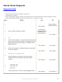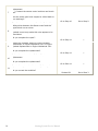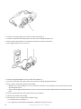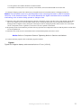
1
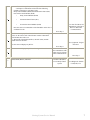
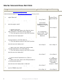
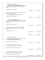
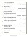
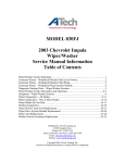
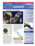
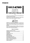
STARTING SYSTEM
Model 811FJ
SERVICE MANUAL
2003 Chevrolet Impala
ATech Training, Inc.
12290 Chandler Drive
Walton, KY 41094 USA
Toll Free: 1-888-738-9924
Phone: (859) 485-7229 • Fax (859) 485-7299
Email: [email protected]
Website: www.atechtraining.com
Copyright – 2011
1
2
Table of Contents
Starting System Schematics........................................................................................................................ 1
Starting System Description and Operation .......................................................................................... 4
Starter Usage..................................................................................................................................................... 5
Diagnostic System Check - Engine Electrical ........................................................................................ 6
Starter Solenoid Does Not Click ................................................................................................................. 8
Starter Solenoid Clicks, Engine Does Not Crank ............................................................................... 12
Engine Cranks Slowly ................................................................................................................................... 14
Starter Noise Diagnosis ............................................................................................................................... 15
Starter Replacement (3.4L) ....................................................................................................................... 17
Battery Description and Operation.......................................................................................................... 20
Battery Inspection/Test ............................................................................................................................... 22
Battery Charging ............................................................................................................................................ 26
Jump Starting in Case of Emergency ..................................................................................................... 28
Battery Disconnect Caution........................................................................................................................ 30
Battery Electrical Drain/Parasitic Load Test......................................................................................... 31
Platform Battery Drain Diagnosis Process ............................................................................................ 34
3
4
Engine
ngine Cranking
Red on Trainer,
Black on Vehicle
Starting System Schematics
Starting System-Service Manual
1
PRNDL
2
Starting System-Service Manual
Starting System-Service Manual
3
A/C RLY (CMPR). BCM, CIG/AUX, EXT LTS,
IGN SW, PCM, and WSW Fuses
Starting System Description and Operation
The PG-260D and PG-260G are non-repairable starter motors. They have pole pieces that are arranged
around the armature. Both solenoid windings are energized. The pull-in winding circuit is completed to the
ground through the starter motor. The windings work together magnetically to pull and hold in the
plunger. The plunger moves the shift lever. This action causes the starter drive assembly to rotate on the
armature shaft spline as it engages with the flywheel ring gear on the engine. Moving at the same time,
the plunger also closes the solenoid switch contacts in the starter solenoid. Full battery voltage is applied
directly to the starter motor and it cranks the engine.
As soon as the solenoid switch contacts close, current stops flowing thorough the pull-in winding because
battery voltage is applied to both ends of the windings. The hold-in winding remains energized; its
magnetic field is strong enough to hold the plunger, shift lever, starter drive assembly, and solenoid
switch contacts in place to continue cranking the engine. When the engine starts, pinion overrun protects
the armature from excessive speed until the switch is opened.
When the ignition switch is released from the START position, the START relay opens and battery voltage
is removed from the starter solenoid S terminal. Current flows from the motor contacts through both
windings to the ground at the end of the hold–in winding. However, the direction of the current flow
through the pull–in winding is now opposite the direction of the current flow when the winding was first
energized.
The magnetic fields of the pull-in and hold-in windings now oppose one another. This action of the
windings, along with the help of the return spring, causes the starter drive assembly to disengage and the
solenoid switch contacts to open simultaneously. As soon as the contacts open, the starter circuit is turned
off.
Circuit Description
Moving the ignition switch to the start position sends a 12 volt signal through the PCM (CRANK) fuse in the
Junction Block – Left I/P to the PCM to notify the PCM that a crank status has been requested. 12 volts is
fed through the ABS/PCM fuse in the Junction Block – Left I/P to the coil side of the CRANK RLY relay. The
PCM grounds this circuit when all parameters are met for starting the engine. This closes the CRANK RLY
relay allowing Battery Positive voltage through Fusible Link and through the switch side of the CRANK
relay to the S terminal of the starter solenoid. Ground is found through the engine block.
4
Starting System-Service Manual
Starter Usage
Application
Model
LA1
PG260 D
L36
PG260 G
Starting System-Service Manual
5
Diagnostic System Check - Engine Electrical
Test Description
The numbers below refer to the step numbers on the diagnostic table.
4 Lack of communication may be because of a partial malfunction of the class 2 serial data circuit or
due to a total malfunction of the class 2 serial data circuit. The specified procedure will determine the
particular condition.
5
The symptom list in Symptoms will determine the correct diagnostic procedure to use.
6 The presence of DTCs which begin with “U” indicate some other module is not communicating. The
specified procedure will collect all the available information before you perform tests.
Step
Action
Yes
No
Perform the Battery Inspection/Test. Refer to Battery Inspection/Test .
1
—
Does the battery pass the test?
Go to Step 2
2
1. Install a scan tool.
2. Turn ON the ignition, with the engine OFF.
Go to Scan Tool Does
Not Power Up in Data
Link Communications
Does the scan tool power up?
Go to Step 3
Important: The engine may start during the following step. Turn OFF
the engine as soon as you have observed the Crank power mode.
3
1. Access the Class 2 Power Mode in the Diagnostic Circuit Check
on the scan tool.
2. Rotate the ignition switch through all positions while observing
the Class 2 Power Mode parameter.
Go to Power Mode
Mismatch in Body
Control System
Does the ignition switch parameter reading match the ignition switch
position for all switch positions?
Go to Step 4
6
Starting System-Service Manual
1. Turn ON the ignition, with the engine OFF.
2. Attempt to communicate with each of the following
modules on the class 2 serial data circuit:
Body Control Module (BCM) Instrument Panel Cluster (IPC)
Powertrain Control Module (PCM)
•
Body Control Module (BCM)
4
•
Instrument Panel Cluster (IPC)
•
Powertrain Control Module (PCM)
Go to Scan Tool Does Not
Communicate with Class 2
Device in Data Link
Communications
Does the scan tool communicate with all modules on the class 2
serial data circuit?
Go to Step 5
5
1. Select the Display DTCs function for each module. If using a
Tech 2, use the Class 2 DTC Check feature in order to determine
which modules have DTCs set.
2. Record all of the displayed DTCs, the DTC status, and the
module which set the DTC.
Go to Symptoms - Engine
Electrical
Does the scan tool display any DTCs?
Go to Step 6
Does the scan tool display any DTCs which begin with a "U"?
6
Go to Scan Tool Does
Not Communicate with
Class 2 Device in Data
Link Communications
Go to Step 7
7
Does the scan tool display DTC B1000, B2947, B2948, B2957,
B2058, B2960, B3031, or B3032?
Go to Diagnostic
Trouble Code (DTC)
List in Body Control
System
Starting System-Service Manual
Go to Diagnostic Trouble
Code (DTC) List
7
Starter Solenoid Does Not Click
Step
Action
Yes
No
Schematic Reference: Starting and Charging Schematics
Connector End View Reference: Master Electrical Component List in Wiring Systems
1
Did you perform the Diagnostic System Check for
Engine Electrical?
Go to Step 2
Turn the ignition switch to the START position.
2
3
Does the engine crank?
1. Install a scan tool.
2. With a scan tool, observe the Security Lamp
State parameter in the BCM Security Data list.
3. Turn the ignition switch to the START position.
Does the scan tool display On?
4
Go to Testing for
Intermittent
Conditions and Poor
Connections in Wiring
Systems
Go to Diagnostic
System Check - Theft
Deterrent in Theft
Deterrent
Go to Step 3
Go to Step 4
1. With a scan tool, observe the Crank Request
Signal parameter in the PCM data list.
2. Turn the ignition switch to the START position.
Does the scan tool display Yes?
5
Go to Diagnostic
System Check Engine Electrical
Go to Step 5
Go to Step 13
Go to Step 7
Go to Step 6
1. With a scan tool, observe the Starter Relay
Command parameter in the PCM data list.
2. Turn the ignition switch to the START position.
Does the scan tool display On?
6
1. Turn ON the ignition, with the engine OFF.
2. Verify that the transmission is in Park or
Neutral.
3. With a scan tool, observe the IMS parameter in
the Transmission data list.
Does the scan tool display Park or Neutral?
7
Go to Step 7
Turn the ignition switch to the START position. Do you
hear the CRANK relay click?
Go to Step 10
8
Go
to Transmission
Internal Mode
Switch Logic in
Automatic
Transaxle – 4T65E
Starting System-Service Manual
Go to Step 8
8
1. Turn OFF the ignition.
2. Disconnect the CRANK relay.
3. Turn ON the ignition, with the engine OFF.
4. Connect a test lamp between the battery positive
voltage circuit of the CRANK relay coil and a good
ground.
Does the test lamp illuminate?
9
13
Go to Step 11
Go to Step 23
Go to Step 18
Go to Step 12
Go to Step 14
Go to Step 15
Go to Step 21
Go to Step 17
Go to Step 28
Go to Step 19
Go to Step 28
Go to Step 19
Did the fuse in the jumper open?
1. Turn OFF the ignition.
2. Disconnect the PCM.
3. Connect a test lamp between the crank voltage
circuit of the PCM and a good ground.
4. Turn the ignition to the Start position
Does the test lamp illuminate?
14
Go to Step 16
Connect a 40 amp fused jumper between the battery
positive voltage circuit of the CRANK relay switch
circuit and the supply voltage circuit of the CRANK
solenoid.
Does the engine crank?
12
Go to Step 18
1. Turn OFF the ignition.
2. Disconnect the CRANK relay.
3. Connect a test lamp between the battery positive
voltage circuit of the CRANK relay switch circuit and a
good ground.
Does the test lamp illuminate?
11
Go to Step 22
1. Connect a test lamp between the battery positive
voltage circuit of the CRANK relay coil and the control
circuit of the CRANK relay
2. Turn the ignition to the START position.
Does the test lamp illuminate?
10
Go to Step 9
Test the supply voltage circuit of the starter solenoid
for a short to ground. Refer to Circuit
Testing and Wiring Repairs in Wiring Systems.
Did you find and correct the condition?
15
Test the supply voltage circuit of the starter solenoid
for a high resistance or open. Refer to Circuit
Testing and Wiring Repairs in Wiring Systems.
Did you find and correct the condition?
Starting System-Service Manual
9
16
Test the control circuit of the CRANK relay for an open
or a short to battery voltage. Refer to Circuit
Testing and Wiring Repairs in Wiring Systems.
Did you find and correct the condition?
17
Go to Step 28
Go to Step 26
Go to Step 28
Go to Step 27
Go to Step 28
Go to Step 28
—
—
Replace the CRANK relay.
Is the repair complete?
10
Go to Step 25
Repair an open or high resistance in the battery
positive voltage circuit of the Starter relay switch.
Refer to Wiring Repairs in Wiring Systems.
Is the repair complete?
24
Go to Step 28
Repair an open or high resistance in the battery
positive voltage circuit of the Starter relay coil. Refer
to Wiring Repairs in Wiring Systems.
Did you complete the repair?
23
Go to Step 24
Inspect for poor connections at the PCM harness
connectors. Refer to Testing for Intermittent Conditions
and Poor Connections and Connector Repairs in Wiring
Systems.
Did you find and correct the condition?
22
Go to Step 28
Inspect for poor connections at the ignition switch.
Refer to Testing for Intermittent Conditions and Poor
Connections and Connector Repairs in Wiring Systems.
Did you find and correct the condition?
21
Go to Step 20
Inspect for poor connections at the starter solenoid.
Refer to Testing for Intermittent Conditions and Poor
Connections in Wiring Systems.
Did you find and correct the condition?
20
Go to Step 28
Inspect for poor connections at the CRANK relay. Refer
to Testing for Intermittent Conditions and Poor
Connections and Connector Repairs in Wiring Systems.
Did you find and correct the condition?
19
Go to Step 21
Test the crank voltage circuit of the PCM for an open or
high resistance. Refer to Circuit Testing and Wiring
Repairs in Wiring Systems.
Did you find and correct the condition?
18
Go to Step 28
Go to Step 28
Starting System-Service Manual
—
25
Replace the starter motor. Refer to Starter
Replacement
Did you complete the replacement?
26
Go to Step 28
—
Replace the ignition switch. Refer to Ignition and Start
Switch Replacement in Instrument Panel, Gauges and
Console.
Is the repair complete?
Go to Step 28
—
IMPORTANT:: Perform the set up procedures for the
PCM.
27
Replace the PCM. Refer to Powertrain Control Module
Replacement in Engine Controls - 3.4L or Powertrain
Control Module Replacement in Engine Controls - 3.8L.
Did you complete the replacement?
28
Go to Step 28
—
Operate the system in order to verify the repair.
Did you find and correct the condition?
Starting System-Service Manual
System OK
Go to Step 2
11
Starter Solenoid Clicks, Engine Does Not Crank
Step
Action
Yes
No
Schematic Reference: Starting and Charging Schematics
1
Did you perform the Diagnostic System Check for
Engine Electrical?
Go to Step 2
2
Turn the ignition switch to the START position.
Did the starter solenoid click one time?
Go to Step 3
Inspect the engine and belt drive system for mechanical
binding (seized engine, seized generator).
3
Does the engine move freely?
Go to Step 4
4
Go to Step 10
Go to Step 5
Go to Step 10
Go to Step 6
Go to Step 10
Go to Step 7
Test the ground of the starter motor between the
battery and the starter motor for a high resistance.
Refer to Circuit Testing and Wiring Repairs in Wiring
Systems.
Did you find and correct the condition?
12
Go to Engine Will Not
Crank - Crankshaft
Will Not Rotate in
Engine Mechanical –
3.4L or Engine Will
Not Crank Crankshaft Will Not
Rotate in Engine
Mechanical – 3.8L
Test the battery positive cable between the Engine
Harness Wiring Junction Block (TOP) and the starter
motor for an open or high resistance. Refer to Circuit
Testing and Wiring Repairs in Wiring Systems.
Did you find and correct the condition?
6
Go to Starter Solenoid
Does Not Click
Test the battery positive cable between the battery and
the Engine Harness Wiring Junction Block (TOP) for an
open or high resistance. Refer to Circuit
Testing and Wiring Repairs in Wiring Systems.
Did you find and correct the condition?
5
Diagnostic System
Check - Engine
Electrical
Starting System-Service Manual
7
Inspect for poor connections at the Engine Harness
Wiring Junction Block (TOP). Refer to Testing for
Intermittent Conditions and Poor
Connections and Connector Repairs in Wiring
Systems.
Did you find and correct the condition?
8
Go to Step 8
Go to Step 10
Go to Step 9
Inspect for poor connections at the starter motor.
Refer to Testing for Intermittent Conditions and Poor
Connections and Connector Repairs in Wiring Systems.
Did you find and correct the condition?
9
Go to Step 10
Replace the starter motor. Refer to Starter
Replacement.
Is the repair complete?
10
Go to Step 10
—
Operate the system in order to verify the repair.
Did you find and correct the condition?
Starting System-Service Manual
System OK
Go to Step 2
13
Engine Cranks Slowly
Inspect the following items:
• Battery—Perform the Battery Inspection/Test. Refer to Battery Inspection/Test .
• Wiring—Inspect the wiring for damage. Inspect all connections to the starter motor, the solenoid, the battery, and all ground
connections. Refer to:
- Circuit Testing
- Wiring Repairs
- Testing for Intermittent Conditions and Poor Connections
- Connector Repairs
• Engine—Verify that the engine is not seized.
If the battery, the wiring, and the engine are functioning properly, and the engine continues to crank
slowly, replace the starter motor. Refer to Starter Replacement.
14
Starting System-Service Manual
Starter Noise Diagnosis
Diagnostic Aids
• Inspect the flywheel ring gear for damage or unusual wear.
• Shim the starter as required.
• In order to add pinion to ring gear clearance a full size shim must be used. Do not shim only one starter mounting bolt. There
are three shims available in different shapes, for clearance, all are 1 mm (0.039 in.) thick.
Step
1
Action
Yes
Did you perform the Diagnostic System Check?
Go to Step 2
Start the engine.
2
Does the starter operate normally?
Go to Testing for
Intermittent
Conditions and Poor
Connections in
Wiring Systems
No
Go to Diagnostic
System Check Engine Electrical
Go to Step 3
Start the engine while listening to the starter motor
turn.
3
4
Is there a loud "whoop", it may sound like a siren if the
engine is revved while the starter is engaged, after the
engine starts, but while the starter is still held in the
engaged position?
Do you hear a "rumble", a "growl", or, in some cases, a
"knock" as the starter is coasting down to a stop after
starting the engine?
Go to Step 6
Go to Step 4
Go to Step 7
Go to Step 5
Go to Step 8
Go to Step 7
Go to Step 9
Go to Step 10
Important: This is often diagnosed as a starter drive
gear hang-in or a weak solenoid.
5
When the engine is cranked, do you hear a highpitched whine after the engine cranks and starts
normally?
Inspect the flywheel ring gear for the following:
• Chipped gear teeth
6
• Missing gear teeth
• Milled teeth
Is the flywheel bent, or does it have damaged teeth?
Starting System-Service Manual
15
7
1. Remove the starter motor. Refer to Starter
Replacement.
2. Inspect the starter motor bushings and clutch
gear.
Does the clutch gear have chipped or milled teeth or
worn bushings?
Go to Step 10
Go to Step 9
Go to Step 11
—
Go to Step 11
—
Go to Step 11
—
System OK
Go to Step 3
Shim the starter motor away from the flywheel by
adding shims between the starter motor and the
engine block one at a time.
8
Flywheel runout may make this noise appear to be
intermittent.
Did you complete the repair?
9
Replace the flywheel. Refer to Engine Flywheel
Replacement in Engine Mechanical 3.4L or Engine
Flywheel Replacement in Engine Mechanical 3.8L.
Did you complete the replacement?
10
Replace the starter motor. Refer to Starter
Replacement.
Did you complete the replacement?
11
Operate the system in order to verify the repair.
Did you correct the condition?
16
Starting System-Service Manual
Starter Replacement (3.4L)
Removal Procedure
Important: The starter motor on this vehicle is NOT serviceable and must be replaced as a complete unit.
1. Disconnect the negative battery cable. Refer to Battery Negative Cable Disconnection and Connection .
2. Raise and support the vehicle. Refer to Lifting and Jacking the Vehicle in General Information.
3. Remove the lower air deflector. Refer to Radiator Air Lower Baffle and Deflector Replacement in Engine Cooling.
4. Remove the torque converter covers. Refer to Torque Converter Cover Replacement in Automatic Transaxle – 4T65-E.
5. Remove the starter solenoid BAT terminal nut (8) and the positive battery cable (9) from the starter motor.
6. Remove the starter solenoid S terminal nut (7) and the starter solenoid wire (6) from the starter motor.
Starting System-Service Manual
17
7. Remove the starter bolts (1, 2) and the starter motor.
Installation Procedure
1. Align the starter motor to the engine.
Notice: Use the correct fastener in the correct location. Replacement fasteners must be the correct part
number for that application. Fasteners requiring replacement or fasteners requiring the use of thread
locking compound or sealant are identified in the service procedure. Do not use paints, lubricants, or
corrosion inhibitors on fasteners or fastener joint surfaces unless specified. These coatings affect fastener
torque and joint clamping force and may damage the fastener. Use the correct tightening sequence and
specifications when installing fasteners in order to avoid damage to parts and systems
18
Starting System-Service Manual
2. Install the starter motor bolts (1, 2) finger tight until seated.
Tighten
Tighten the bolts to 43 N·m (32 lb-ft).
3. Install the positive battery cable (9) and the solenoid BAT terminal nut (8) finger tight to the starter motor.
Install the starter solenoid wire (6) and the starter solenoid S terminal nut (7) finger tight to the starter motor.
Tighten
• Tighten the solenoid BAT terminal nut (8) to 10 N·m (89 lb-in).
• Tighten the starter solenoid S terminal nut (7) to 2.3 N·m (20.5 lb-in).
4. Install the torque converter covers. Refer to Torque Converter Cover Replacement in Automatic Transaxle – 4T65-E.
5. Install the lower air deflector. Refer to Radiator Air Lower Baffle and Deflector Replacement in Engine Cooling.
6. Lower the vehicle.
7. Connect the negative battery cable. Refer to Battery Negative Cable Disconnection and Connection .
Starting System-Service Manual
19
Battery Description and Operation
Caution: Batteries produce explosive gases, contain corrosive acid, and supply levels of electrical current high enough to cause
burns. Therefore, to reduce the risk of personal injury when working near a battery:
• Always shield your eyes and avoid leaning over the battery whenever possible.
• Do not expose the battery to open flames or sparks.
• Do not allow the battery electrolyte to contact the eyes or the skin. Flush immediately and thoroughly any contacted areas
with water and get medical help.
• Follow each step of the jump starting procedure in order.
• Treat both the booster and the discharged batteries carefully when using the jumper cables.
Important: Because of the materials used in the manufacture of automotive lead-acid batteries, dealers
and service shops that handle them are subject to various regulations issued by OSHA, EPA, DOT, and
various state or local agencies. Other regulations may also apply in other locations. Always know and
follow these regulations when handling batteries.
Batteries that are no longer wanted must be disposed of by an approved battery recycler and must never
be thrown in the trash or sent to a landfill.
Batteries that are not part of the vehicle itself, not the battery under the hood, must only be transported
on public streets for business purposes via approved hazardous material transportation procedures.
Battery storage, charging and testing facilities in repair shops must meet various requirements for
ventilation, safety equipment, material segregation, etc.
The maintenance free battery is standard. There are no vent plugs in the cover. The battery is completely
sealed except for 2 small vent holes in the side. These vent holes allow the small amount of gas that is
produced in the battery to escape.
20
Starting System-Service Manual
The battery has 3 functions as a major source of energy:
• Engine cranking
• Voltage stabilizer
• Alternate source of energy with generator overload
The battery specification label, example below, contains information about the following:
• The test ratings
• The original equipment catalog number
• The recommended replacement model number
Battery Ratings
A battery has 2 ratings:
• Reserve capacity
• Cold cranking amperage
When a battery is replaced use a battery with similar ratings. Refer to the battery specification label on
the original battery or refer to Battery Usage.
Reserve Capacity
Reserve capacity is the amount of time in minutes it takes a fully charged battery, being discharged at a
constant rate of 25 amperes and a constant temperature of 27°C (80°F) to reach a terminal voltage of
10.5 volts. Refer to Battery Usage for the reserve capacity rating of the original equipment battery.
Cold Cranking Amperage
The cold cranking amperage is an indication of the ability of the battery to crank the engine at cold
temperatures. The cold cranking amperage rating is the minimum amperage the battery must maintain for
30 seconds at –18°C (0°F) while maintaining at least 7.2 volts. Refer to Battery Usage for the cold
cranking amperage rating for this vehicle.
Starting System-Service Manual
21
Battery Inspection/Test
Tools Required
J 42000 Battery Tester
Diagnostic Aids
Caution: Refer to Battery Disconnect Caution in Cautions and Notices.
Important: The battery test using the J 42000 requires correct connections to the battery terminals. A
failure to obtain the correct connections during the test may result in a failed test on a good battery.
Follow these instructions in order to avoid an incorrect diagnosis because of connections:
• If testing the vehicle with the battery cables still connected, wiggle the J 42000 clips on the terminal bolt. This may cut
through any coating or through any oxidation that may be present on the bolt.
Even new bolts contain a protective coating that may insulate or cause a resistance in the test circuit.
• If correct connections to the battery terminal bolts in the vehicle are in doubt, perform the following steps:
- Disconnect the negative battery cable.
- Disconnect the positive battery cable.
- Install the test adapters on the terminals.
- Follow the instructions for an Out-of-Vehicle test.
• If the tester displays a REPLACE BATTERY or BAD CELL-REPLACE result for a battery tested in the vehicle with the
battery cables connected, perform the following steps:
- Disconnect the negative battery cable.
- Disconnect the positive battery cable.
- Install the tester adapters.
- Follow the instructions for an Out-of-Vehicle test.
- Replace the battery only if the Out-of-Vehicle test shows a REPLACE BATTERY or BAD CELL-REPLACE result. This
prevents battery replacements that are due only to faulty battery cable connections.
• Use the correct terminal adapters.
Do not use any common bolts or a combination of bolts, nuts, and or washers as adapters when testing the battery.
Use the test adapters that are provided with the J 42000 or P/N 12303040 terminal adapters. If the adapters that are provided
with the J 42000 require replacement, use P/N 12303040. Any other adapter may not contact the correct areas of the battery
terminal, causing a resistance that may result in an invalid battery test result.
Step
Action
Values
Yes
No
Caution:: Refer to Battery Disconnect Caution in Cautions and Notices.
Important: Always write the test code displayed by the tester on the repair order for any warranty
purposes. The number is a unique code that describes the test data for a particular battery at a particular
time. The test code may occasionally repeat when you retest the same battery. More often, each test will
22
Starting System-Service Manual
result in a different code. If the battery is replaced due to failing the test, only an Out-of-Vehicle test
code is valid for warranty purposes.
1
Inspect the battery for a cracked, broken, or
damaged case, which may be indicated by
battery acid leakage.
—
Is the battery OK?
2
Go to Step 2 Go to Step 15
Compare the cold cranking amperage (CCA)
and reserve capacity (RC) of the battery to the
original battery or original equipment (OE)
specification. Refer to Battery Usage.
—
Does the battery meet or exceed the
specifications?
3
1. Turn OFF the ignition.
2. Attempt to rotate the negative battery
cable connector clockwise with light finger
pressure.
Go to Step 3 Go to Step 15
—
Does the negative connector rotate?
4
Use a torque wrench in order to verify the
torque to loosen the negative battery terminal
bolt.
5
Go to Step 5
Go to Step 9
Go to Step 8
Go to Step 7
Go to Step 6
Go to Step
14
Go to Step 8
10 N·m (88 lb-in)
Is the torque above the specified value?
Attempt to rotate the positive battery cable
connector clockwise with light finger pressure.
Go to Step 4
—
Does the positive connector rotate?
Important: Ensure that all of the electrical
loads are turned OFF.
6
1. Install the J 42000 Battery Tester.
2. Follow the directions supplied with the
tester for an In-Vehicle test.
3. Follow any directions displayed on the
tester.
4. If the tester calls for charging the
battery, refer to Battery Charging.
—
Did the tester pass the battery?
Starting System-Service Manual
23
7
Use a torque wrench in order to verify the
torque to loosen the positive battery terminal
bolt.
10 N·m (88 lb-in)
Is the torque above the specified value?
8
1. Disconnect the negative battery cable.
2. Disconnect the positive battery cable.
3. Clean and wire brush the lead face of
both battery terminals and the metal contact
rings in both cable connectors.
4. Remove the bolts from the cable
connectors in order to provide access to the
connector rings as needed.
5. If either of the battery terminals or the
cable rings are excessively damaged or
corroded, replace as needed.
Go to Step
10
Go to Step 8
Go to Step
11
—
Go to Step
10
—
Go to Step
11
—
—
Did you complete the repair?
1. Disconnect the negative battery cable.
2. Inspect for the following conditions and
repair as needed:
The cable bolt is too long or deformed at the
end. There is foreign material present inside
the nut in the battery terminal Damage to the
battery terminal face or cable connector ring
9
• The cable bolt is too long or deformed at the
end.
• There is foreign material present inside the nut
in the battery terminal
• Damage to the battery terminal face or cable
connector ring
Did you complete the repair?
1. Disconnect the positive battery cable.
2. Inspect for the following conditions and
repair as needed:
The cable bolt is too long or deformed at the
end There is foreign material present inside the
nut in the battery terminal Damage to the
battery terminal face or cable connector ring
10
• The cable bolt is too long or deformed at the
end
• There is foreign material present inside the nut
in the battery terminal
• Damage to the battery terminal face or cable
connector ring
—
Did you complete the repair?
24
Starting System-Service Manual
Important: Ensure that both battery cables
are disconnected and proper adapters are
installed in the battery terminals.
11
1. Install the J 42000.
2. Follow the directions supplied with the
tester for an Out-of-Vehicle test.
3. Follow any directions displayed on the
tester.
4. If the tester calls for charging the
battery, refer to Battery Charging.
—
Did the tester pass the battery?
12
Go to Step
12
Go to Step 15
Go to Step
13
—
Battery OK
—
Battery OK
—
Battery OK
—
1. Press the CODE button on the J
42000.
2. For warranty purposes, write the
displayed code on the repair order.
Did you complete this action?
1. Connect the positive battery cable to
the battery's positive terminal.
2.
Notice: Refer to Fastener Notice in
Cautions and Notices.
13
Tighten the positive battery cable bolt to
the specified value.
3. Connect the negative battery cable
to the battery negative terminal.
4. Tighten the negative battery cable
bolt to the specified value.
15 N·m (11 lb-ft)
Are the cable bolts properly tightened?
14
1. Press the CODE button on the J
42000.
2. For warranty purposes, write the
displayed code on the repair order.
Did you complete the replacement?
15
Replace the battery. Refer to Battery
Replacement.
—
Did you complete the replacement?
Starting System-Service Manual
25
Battery Charging
Tools Required
J 42000 Battery Tester
• For best results, use an automatic taper-rate battery charger with a voltage capability of 16 volts.
• The charging area should be well ventilated.
• Do not charge a battery that appears to be frozen. Allow the battery to warm to room temperature and test it using the J
42000 before charging.
Charging Time Required
The time required to charge a battery will vary depending upon the following factors:
• The battery charger capacity—The higher the charger's amperage, the less time it will take to charge the battery.
• The state-of-charge of the battery—A completely discharged battery requires more than twice as much charging time as a
half charged battery. In a discharged battery with a voltage below 11 volts, the battery has a very high internal resistance
and may only accept a very low current at first. Later, as the charging current causes the acid content to increase in the
electrolyte, the charging current will increase. Extremely discharged batteries may not activate the reversed voltage
protection in some chargers. Refer to the manufacturers instructions for operating this circuitry.
• The temperature of the battery—The colder the battery is, the more time it takes to recharge the battery. The charging current
accepted by a cold battery is very low at first. As the battery warms, the charging current will increase.
Charging Procedure
Notice: Turn OFF the ignition when connecting or disconnecting the battery cables, the battery charger or
the jumper cables. Failure to do so may damage the ECM/PCM or other electronic components.
Notice: Use the correct fastener in the correct location. Replacement fasteners must be the correct part
number for that application. Fasteners requiring replacement or fasteners requiring the use of thread
locking compound or sealant are identified in the service procedure. Do not use paints, lubricants, or
corrosion inhibitors on fasteners or fastener joint surfaces unless specified. These coatings affect fastener
torque and joint clamping force and may damage the fastener. Use the correct tightening sequence and
specifications when installing fasteners in order to avoid damage to parts and systems.
When charging side-terminal batteries with the battery cables connected, connect the charger to the
positive cable bolt and to a ground located away from the battery. When charging side-terminal batteries
with the battery cables disconnected, install the battery side terminal adapters and connect the charger to
the adapters.
Tighten
Tighten the battery side terminal adapters to 15 N·m (11 lb-ft).
Use the following procedure to charge the battery:
1. Turn OFF the charger.
2. Ensure that all of the battery terminal connections are clean and tight.
3. Connect the charger positive lead to the battery positive terminal on the Battery or Fuse Block – Underhood.
26
Starting System-Service Manual
Notice: Do not connect the negative charger lead to the housings of other vehicle electrical accessories or
equipment. The action of the battery charger may damage such equipment.
4. Connect the negative charger lead to a solid engine ground or to a ground stud in the engine compartment that is connected
directly to the battery negative terminal, but away from the battery. If the negative battery cable is disconnected and a terminal
adapter is being used, connect directly to the adapter.
5. Turn ON the charger and set to the highest setting for normal charging.
6. Inspect the battery every half hour after starting the battery charger.
• Charge the battery until the taper-rate charger indicates that the battery is fully charged.
• Estimate the battery temperature by feeling the side of the battery. If it feels hot to the touch or its temperature is over 45°C
(125°F), discontinue charging and allow the battery to cool before resuming charging.
7. After charging, test the battery. Refer to Battery Inspection/Test.
Starting System-Service Manual
27
Jump Starting in Case of Emergency
Caution: Batteries produce explosive gases. Batteries contain corrosive acid. Batteries supply levels of electrical current high
enough to cause burns. Therefore, in order to reduce the risk of personal injury while working near a battery, observe the
following guidelines:
• Always shield your eyes.
• Avoid leaning over the battery whenever possible.
• Do not expose the battery to open flames or sparks.
• Do not allow battery acid to contact the eyes or the skin.
• Flush any contacted areas with water immediately and thoroughly.
• Get medical help.
Notice: This vehicle has a 12 volt, negative ground electrical system. Make sure the vehicle or equipment
being used to jump start the engine is also 12 volt, negative ground. Use of any other type of system will
damage the vehicle's electrical components.
1. Position the vehicle with the booster battery so that the jumper cables will reach.
• Do not let the 2 vehicles touch.
• Make sure that the jumper cables do not have loose ends, or missing insulation.
2. Place an automatic transmission in PARK. If equipped with a manual transmission, place in NEUTRAL and block the wheels.
3. Turn OFF all electrical loads on both vehicles that are not needed.
4. Turn OFF the ignition on both vehicles.
5. Connect the red positive (+) cable to the battery positive (+) terminal (2) of the vehicle with the discharged battery.
Use a remote positive (+) terminal if the vehicle has one.
6. Connect the red positive (+) cable to the positive (+) terminal (1) of the booster battery.
Use a remote positive (+) terminal if the vehicle has one.
7. Connect the black negative (-) cable to the negative (-) terminal (3) of the booster battery.
Caution: Do not connect a jumper cable directly to the negative terminal of a discharged battery to prevent sparking and
28
Starting System-Service Manual
possible explosion of battery gases.
8. The final connection is made to a heavy, unpainted metal engine part (4) of the vehicle with the discharged battery.
This final attachment must be at least 46 cm (18 in) away from the dead battery.
9. Start the engine of the vehicle that is providing the boost.
Notice: Never operate the starter motor more than 15 seconds at a time without pausing in order to allow
it to cool for at least 2 minutes. Overheating will damage the starter motor.
10. Crank the engine of the vehicle with the discharged battery.
11. The black negative (-) cable must be first disconnected from the vehicle that was boosted (4).
12. Disconnect the black negative (-) cable from the negative (-) terminal (3) of the booster battery.
Notice: Do not let the cable end touch any metal. Damage to the battery and other components may
result.
13. Disconnect the red positive (+) cable from the positive (+) terminal (1) of the booster battery.
14. Disconnect the red positive (+) cable from the remote positive (+) terminal (2) of the vehicle with the discharged battery.
Starting System-Service Manual
29
Battery Disconnect Caution
Caution: Before servicing any electrical component, the ignition key must be in the OFF or
LOCK position and all electrical loads must be OFF, unless instructed otherwise in
these procedures. If a tool or piece of equipment could come into contact with a live
exposed electrical connection, then it is advisable to also disconnect the negative
battery cable. Failure to follow these precautions may cause personal injury and/or
damage to the vehicle or its components.
30
Starting System-Service Manual
Battery Electrical Drain/Parasitic Load Test
Tools Required
J 38758 Parasitic Draw Test Switch
Caution: Refer to Battery Disconnect Caution in Cautions and Notices.
Notice: Do not turn the parasitic draw test switch to the OFF position with the engine running. Damage
will occur to the vehicle's electrical system.
Notice: The test switch must be in the ON position when removing the fuses in order to maintain
continuity in the electrical system. This avoids damaging the digital multimeter due to accidental
overloading, such as a door being opened to change a fuse.
Important: The switch knob (1) on the J 38758 is marked ON and OFF. When the switch knob is in the
ON position, the circuit is closed and electrical current will pass through the switch. When the switch knob
is in the OFF position, the circuit is open and electrical current will not pass through the switch.
1. Disconnect the battery negative cable from the battery negative terminal.
2. Install the male end of the J 38758 to the battery ground terminal.
3. Turn the J 38758 knob (1) to the OFF position.
4. Install the battery negative cable to the female end of the J 38758.
5. Turn the J 38758 knob to the ON position.
6. Road test the vehicle and activate all of the accessories, including the radio and the air conditioning.
7. Park the vehicle. Turn the ignition switch to the OFF position and remove the ignition switch key.
Starting System-Service Manual
31
8. Connect a 10 A fused jumper wire to the test switch tool terminals (1).
9. Turn the J 38758 knob to the OFF position. The current flows through the jumper wire.
10. Wait 1 minute. If the fuse blows use an inductive ammeter to locate the current draw.
11. Set a digital multimeter to the 10 A scale.
12. Connect the digital multimeter to the test switch tool terminals (1).
13. Turn the J 38758 knob to the OFF position. The current flows through the digital multimeter.
14. Wait 1 minute. Check and record the current reading.
• When there is a current reading of 2 A or less, turn the J-38758 knob to the ON position. The electrical current will now
pass through the switch.
• Then, switch the digital multimeter down to the 2 A scale for a more accurate reading when the J 38758 knob is turned
OFF.
15. Turn the J 38758 knob to the OFF position. Wait at least 20 minutes.
16. Check and record the current reading.
17. Note the battery reserve capacity. Refer to Battery Usage.
17.1 Divide the reserve capacity by 4.
17.2 Compare this to the multimeter milliampere reading taken in the previous step.
32
Starting System-Service Manual
17.2 The parasitic current drain should not exceed this number.
17.2 Example: If a battery has a reserve capacity of 100 minutes, the current drain should not exceed 25 mA.
18. Check the charging system if the vehicle has an acceptable amount of current drain. Refer to Charging System Test.
Notice: The test switch must be in the ON position when removing the fuses in order to maintain
continuity in the electrical system. This avoids damaging the digital multimeter due to accidental
overloading, such as a door being opened to change a fuse.
19. When the vehicle has an unacceptable amount of parasitic current drain, remove each fuse one at a time until the current drain
falls to an acceptable level. This will indicate which circuit is causing the drain. Refer to Power Distribution Schematics in
Wiring Systems to diagnose exactly which part of the suspect circuit is causing the parasitic drain. In some cases a non-fused
circuit or component, such as a generator, is the cause of excessive parasitic current drain.
20. Repeat the parasitic current drain test procedure after any repair has been completed to make sure that the parasitic current drain
is at an acceptable level.
21. When the cause of the excessive current draw has been located and repaired, remove the J 38758.
Notice: Refer to Component Fastener Tightening Notice in Cautions and Notices.
22. Connect the battery negative cable to the battery negative terminal.
Tighten
Tighten the negative battery cable terminal bolt to 17 N·m (13 lb ft).
Starting System-Service Manual
33
Platform Battery Drain Diagnosis Process
Subject: Class 2 Platform Battery Drain Diagnosis Process
Models: 1996 -2008 Passenger Cars and Light Trucks that use Class 2 Communications
The following diagnosis might be helpful if the vehicle exhibits the symptom(s) described in this PI.
Condition/Concern:
Platform Battery Drain Diagnosis Process - Battery is discharged for no apparent reason while vehicle is
parked and locked - Intermittent draw and/or possible continuous draw(s) that slowly renders the battery
below its serviceable voltage amperage level.
Please follow this process entirely:
1. Define the conditions which trigger the discharged battery:
• How long does it take for the battery to discharge? This step will help determine if the draw is large or small. Normally a
draw, which takes the battery level down overnight after operating the vehicle the day before, is rather large and is related to
a switch, relay or other electric/mechanical device. Small amounts of drain which take several days to take the battery from a
good state of charge to below the level required to start the engine can be small single bulbs or modules which are either not
going to sleep when they should, or waking up intermittently for some unknown reason.
• How many times has it happened to the customer? This step will determine if this is a Random occurrence and/or
intermittent.
• Does it always happen in the same location? Is there some outside influence that surrounds the vehicle that needs to be taken
into account? This is most unlikely, but worth checking-out.
• Describe the customer's driving habits. Does the battery get to a state of being fully charged on a regular basis or is this
vehicle unable to crank due to a generally low state of charge?
• Is the vehicle equipped with any non-original equipment including cell phone, remote starter, extra lighting, radio, CD player,
LOJAK, etc. or OnStar (either dealer or factory installed)? All of these items can be wired in such a way to either constantly
draw amperage, which they shouldn't, or in some way affect the class 2 modules on this vehicle and/or the battery and
charging system.
• Does the customer leave the key in the ignition? Leaving the key in the ignition does not generally cause a problem, but if the
customer does not come back to the locked ignition position after shutting the engine off however, many draws will be
induced. This draw will not be reduced and/or eliminated; this type of draw is due to the fact that the system is designed to
keep certain modules awake with the key in this position.
• What is the previous history on this car, what parts have been replaced, what repairs have been performed either in an attempt
to correct this situation or that might impact it? Are there any other reported problems with the vehicle which may relate to a
discharged battery concern - items which were previously reported/corrected and/or currently exist that the customer (car
recently bought used) does not recognize as a problem or the used car manager reporting the discharged battery is unaware
of? Recent repairs may or may not relate to draw diagnosis; i.e. the IPC was replaced recently.
2. Perform a good visual and physical inspection of the battery cables. CHECK TORQUE OF BATTERY CABLE BOLTS. If
loose, check for signs of arcing and corrosion etc., grounds and power leads to and from each of these, or BOLT MATERIAL
IN BATTERY THREADS, THERMISTOR (if equipped) CONNECTOR FOR PROPER SEATING AND TIGHTNESS. What
are the results of a battery/CHARGING SYSTEM test?
• Perform a generator output test and a terminal drag test on generator terminal L.
• Fuses related to this concern: check for loose fuses in trunk and engine compartment bussed electrical center by rocking each
fuse with one finger, which may help identify the fuse. The only repairs that may be made to the electrical center are
replacement of plug-in devices and mounting hardware, as follows: fuses, relays, circuit breakers, electrical center cover,
battery stud cover, and other snap-on covers, cover attachment thumb screw, labels for fuse/relay identification, splash
shields, and mounting brackets
34
Starting System-Service Manual
3. What DTCs are currently present or have been recorded on previous visits to the dealer? Correct as per the appropriate service
manual.
4. Road test vehicle for 30-40 minutes, activate all accessories. Open and close all doors, windows, deck lid, etc. CYCLE
LUMBAR AND SEAT SWITCHES along with all other manually operated switches including the trunk release, fuel door
release, garage door opener, and valet that have power to them all the time while the car is sitting. Don't forget to look FOR A
STUCK SWITCH/RELAY.
5. What is the parasitic draw on the vehicle after a 25-minute power down cycle? Using parasitic draw test switch tool J38758 and
DVOM J39200, perform a parasitic draw test as per the procedure in the Engine Electrical section Service Information. Record
the draw and read the reserve capacity of the battery in the vehicle. Divide the reserve capacity by four (4) and the draw present
should not exceed this number. Example: If the battery has a reserve capacity of 100 amperes, the current draw should not
exceed 25 mA on the DVOM. See SI for acceptable draw limits for each module the vehicle may be equipped with. Keep in
mind the draw created by the OnStar system for the first 48 hours from ignition off.
• OnStar typical power consumption
- ANALOG: The system will cycle every 10 minutes and cause a spike to approximately 250 mA for
about ten seconds, taper down to 75 mA for another 45 seconds and go to less than one mA for the
nine minutes until the next cycle begins. This is normal. The Class 2 data line should not wake up
during this sequence. This cycle stops if power is removed from the OnStar system for a short period
and will resume once the GPS signal is reacquired.
- DIGITAL: The system will remain in DIGITAL STANDBY for the full 48 hours after the last
ignition cycle. Normally a tech will see a drain that is reading approximately 20 to 70mA with
occasional spikes (will vary) around 175mA. IMPORTANT: In digital mode the OnStar module is
capable of receiving incoming calls and readings may jump to 250mA or more during the call. The
call will normally be only a few seconds in duration.
• It is vital to monitor the power consumption and not rely on only the MIN/MAX readings on the DVOM. The duration of
the OnStar cycle should reflect the above information. A steady reading (no toggle/fluctuation) in digital standby is
abnormal.
6. If the draw above is determined to be above the appropriate amount for the vehicle involved, are any modules on the class 2
data line staying "active" past the 25-minute time out mentioned above or waking up periodically after this time-out has
passed? If one or more module is waking up, how many times and which module(s)? Use the Tech 2 and use the message
monitor screen with an external power source to the Tech 2 if performing an amp draw test while using message monitor.
Recommendation/Instructions:
Here is a suggested procedure for performing a combination parasitic draw test while monitoring the class
2 devices on the vehicle:
1. Remove terminal 16 from data link connector (DLC).
2. Install tool #J38758 on battery.
3. Connect Fluke 87 to J38758 as described in the Engine Electrical section of the appropriate Service Manual and set to
appropriate amp scale.
4. Connect Tech 2 to DLC
5. Connect 110-volt power supply to DLC end of Tech 2 cable.
6. Turn Tech 2 on
• Main, enter
• Diagnostics enter.
• Year
• Vehicle type
• Diagnostic circuit check
• Class 2 message monitor - remember; only modules which are currently communicating on the Class 2 data line will show up
on the message monitor screen. If the ignition is in the accessory position as an example, the PCM and ABS controller will
not be listed. If a module, which the vehicle is known to be equipped with, does not show up on message monitor when in the
run position, this indicates a problem that needs correction prior to proceeding.
7. Allow the vehicle to sit with all doors closed and without activating any switches etc. until the class 2 system has had
enough time to power down, less than 25 minutes, or use the sleep mode to put all the modules to sleep. Once the sleep
mode is enabled, the first module to "wake up" will be listed first on the message monitor screen with others listed in order
Starting System-Service Manual
35
of "wake up". The time from being put to sleep until the first "wake up" sequence will also be displayed. If a combination
of three or four modules has come active, putting all of the modules back to sleep and pulling the fuse to one module at a
time will help to narrow down which module may be waking up inadvertently. Remember that module "wake up" can be
caused by several factors. They include, but are not limited to:
• input changing states - door switch going open and closed (hi/lo)
• power or ground coming and going to module
• module internal function incorrect
• Or in the case of the power master, amperage draws in excess of low power requirements or another module which has these
or other related concerns. These all can be checked with the Fluke set to 1 millisecond record speed on min/max setting.
8. Open the gate on J38758, and let vehicle sit for another ten (10) minutes and/or use sleep mode.
9. Review the amperage reading.
10. As the amperage draw tapers down below 10 amps, close the J38758 and switch Fluke 87 to milliamp scale and record min/max
on 100-millisecond scale. Open the J38758 again when done. This step will allow the Fluke meter to record any spikes and keep
the meter working during the entire sequence. IF MIN/MAX IS NOT SELECTED, THE METER WILL TIME OUT AND
SHUT OFF.
11. After the vehicle has been tested for a minimum of 8 hours, check the number of counts as per message monitor for each
control module, i.e. each time a unit goes from inactive, to active and inactive again. The module(s) with the highest number of
counts may indicate a suspect area. Modules may be waking up on their own, (which is most unlikely) or activated by a switch
input, power fluctuation, poor ground or input from other modules which are being activated.
12. Once it has been determined that the draw is either a component - relay, switch etc., which is stuck or in some way
reduces/contributes to the draw, determine which circuits are specifically involved. Touching and/or removing fuses, relays, and
connectors to suspect components after reviewing the current wiring diagram until the draw is reduced to acceptable levels will
lead to the correct circuit. When exiting the message monitor screen and then re-entering the message monitor screen, the Tech
2 will also wake up modules. DON'T BE FOOLED. Wait for the module(s) to again go to sleep or use the sleep mode function.
13. Back-to-basics:
• Checking ground credibility requires a voltage drop test under load
• ALWAYS TEST FROM THE NEGATIVE SIDE OF THE CIRCUIT - A voltage drop test is performed at various points
along the circuit from the ground side toward the positive side of the circuit until the point of high resistance is located.
• ALWAYS MAKE CERTAIN THAT THE CIRCUIT LOAD IS "ON"
• ALWAYS USE A HIGH IMPEDANCE METER LIKE A FLUKE 87
• THE HIGHER THE VOLTAGE READING, THE HIGHER THE RESISTANCE IN THAT CIRCUIT
• WHEN TESTING, TRY TO ACHIEVE A READING AS CLOSE TO ZERO AS POSSIBLE (USUALLY LESS THAN 25
MILLIVOLTS)
• ALWAYS START WITH A FULLY CHARGED BATTERY!
Please follow this diagnostic or repair process thoroughly and complete each step. If the condition
exhibited is resolved without completing every step, the remaining steps do not need to be performed.
GM bulletins are intended for use by professional technicians, NOT a "do-it-yourselfer". They are written to inform these technicians
of conditions that may occur on some vehicles, or to provide information that could assist in the proper service of a vehicle.
Properly trained technicians have the equipment, tools, safety instructions, and know-how to do a job properly and safely. If a
condition is described, DO NOT assume that the bulletin applies to your vehicle, or that your vehicle will have that condition. See
your GM dealer for information on whether your vehicle may benefit from the information.
36
Starting System-Service Manual
WE SUPPORT
VOLUNTARY
TECHNICIAN
CERTIFICATION