1
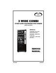
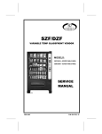
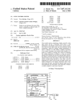
COLD FROZEN SATELLITE FOOD VENDOR CF-1000USD/FF-2000USD MODELS: 3514 / 3514A- COLD FOOD 3513 / 3513A - FROZEN FOOD SERVICE MANUAL November 2008 4216294 Rev A TABLE OF CONTENTS INTRODUCTION ................................................................ 2 SPECIFICATIONS .............................................................. 3 UNPACKING ...................................................................... 4 REMOVE SHIPPING PALLET ......................................... 4 INSTALLATION .................................................................. 4 CHECKLIST ..................................................................... 4 LOCATE NEXT TO THE HOST ....................................... 5 SAFETY & INSTALLATION GUIDELINES ......................... 6 INTRODUCTION ............................................................. 6 INITIAL INSTALLATION .................................................. 6 GROUNDING & ELECTRICAL ........................................ 6 ELECTRICAL HAZARDS................................................. 7 REFRIGERATION HAZARDS ......................................... 8 MECHANICAL HAZARDS ............................................... 8 TEMPERATURE HAZARDS ............................................ 8 SUBSTITUTIONS & MODIFICATIONS ........................... 9 CONNECTING TO THE HOST ...................................... 10 ANCHOR PLATE INSTALLATION................................. 11 LOCATING POWER SWITCH AND SERVICE MODE BUTTON ........................................................................... 11 SERVICE MENU FOR THE USD FF/CF .......................... 12 PRICING THE USD SATELLITE ...................................... 14 HEALTH SAFETY ............................................................. 14 REFRIGERATION CONTROL .......................................... 15 LOADING INSTRUCTIONS .............................................. 16 AUGER TIMING ............................................................. 17 TRAY SPACING ............................................................ 17 REFRIGERATION ............................................................ 18 REFRIGERATION TROUBLESHOOTING ..................... 18 REMOVING THE COMPONENT DRAWER ..................... 21 DOOR REMOVAL ............................................................. 22 REFRIGERATION UNIT REMOVAL ................................. 23 CARE & CLEANING ......................................................... 23 STORING THE SATELLITE FOOD VENDOR .................. 24 BEFORE CALLING FOR SERVICE .................................. 24 SCHEMATIC (COLD FOOD USD) .................................... 25 SCHEMATIC (FROZEN FOOD USD) ............................... 26 Record the Model Number and Serial Number of your machine below. The Model and Serial numbers are needed to obtain quick service and parts information for your machine. The numbers are available on the identification plate located on the backside of the cabinet of the machine. MODEL NUMBER: SERIAL NUMBER: 3514 3513 CF 1000USD FF 2000US D ii 4216294 INTRODUCTION This manual should be read thoroughly to become familiar with the functions and features of all components. The initial set-up of a vending machine is a very important step of insuring that the equipment operates in a trouble-free manner. Follow the instructions at the initial installation of the machine to avoid service problems and minimize setup time. NOTE: Unless specified otherwise in this manual, the term Satellite Food Vendor refers to features and/or specifications for both the Cold Food Satellite Vendor and Frozen Food Satellite Vendor. Both models consist of six trays, are multiple select and operates on the ―first-in, first-out‖ vending principle. The selections can be individually priced. Pricing is set at the host vendor controller. It utilizes the electronics of the host vendor for credit accumulation and refund of change when required. The Cold Food Satellite Vendor is designed to vend cold food products that require storage temperatures of 41°F (5°C) or lower. The Frozen Food Satellite Vendor is designed to for the following: Vend frozen foods that require storage temperatures of 0°F (-18°C) or lower. Vend slacking precooked frozen foods that require storage temperatures of 15°F (-9°C) or lower. Vend cold food products that require storage temperatures of 41°F (5°C) or lower. Each machine has a model and a serial number given on the Serial Number Plate attached to the inside or back of the vendor. Record these numbers for your records in the space provided on the inside front cover. All inquires and correspondence pertaining to this vendor should reference the model and serial numbers. Should you have any questions pertaining to the information in the manual, replacement parts or the operation of the vendor you should contact your machine supplier. FOR U.S. UNITS: VendNet 165 North 10th Street Waukee, Iowa 50263-0488 PHONE: 1-515-274-3641 US TOLL FREE: 1-800-833-4411 PARTS FAX: 1-515-987-4447 SALES FAX: 1-515-274-0390 3514 3513 CF1000USD FF2000USD 2 4216294 Rev A SPECIFICATIONS INDOOR USE ONLY CF1000 COLD FOOD SATELLITE VENDOR FF2000 FROZEN FOOD SATELLITE VENDOR 3514 3513 MODEL FOOD TYPE / TEMPERATURE RANGE COLD FOOD 41°F/5°C or lower 41°F/5°C or lower SLACKING PRECOOKED FROZEN FOOD Not Recommended 15°F/-9°C or lower FROZEN FOOD Not Recommended 0°F/-18°C or lower 1/3 HP Hermetically Sealed 1/2 HP Hermetically Sealed REFRIGERANT R-134a R-404a CHARGE 5.9 Oz. REFRIGERATION UNIT SIZE DESIGN PRESSURE ELECTRICAL 32 Oz. (Danfoss) 48 Oz. (Tecumseh) 145HS/20LS PSIG 265HS/14LS PSIG 3514 3514A 3513 3513A 115 VAC 230 VAC 115 VAC 230 VAC HERTZ 60 Hz 50 Hz 60 Hz 60 Hz PHASE 1 Ph 1 Ph 1 Ph 1 Ph 7 Amps 3.5 8 Amps4 VOLTAGE RUNNING AMPS GENERAL HEIGHT 72 inches (183 cm) WIDTH 22 inches (56 cm) DEPTH 33.5 inches (85 cm) 37 inches (94 cm) WEIGHT 513 pounds (233 kg) 523 pounds (237 kg) PRICING SELECTIONS 3514 3513 CF1000USD FF2000USD Multi-Pricing Factory Standard 16 Selections - Maximum 30 Selections 3 4216294 Rev A UNPACKING This machine was thoroughly inspected before leaving the factory and the delivering carrier has accepted it as their responsibility. Any damage or irregularities should be noted at the time of delivery and reported to the carrier. Request a written inspection report from the claims inspector to file any claim for damage. File the claim with the carrier (not the manufacturer) within 15 days after receipt of the vendor. Carefully remove the outside packing material in a manner not to damage the finish or exterior of the machine. Inspect the machine for concealed shipping damage. Report any damage hidden by the shipping material directly to the delivering carrier on a Hidden Damage Report. Record the model number and serial number of the vendor for your records. These numbers are on the Serial Number Plate on the back of the cabinet and/or inside the vendor. Refer to these numbers on all correspondence and inquiries pertaining to this vendor. REMOVE SHIPPING PALLET CAUTION As a safety precaution, removing the vending machine from the shipping pallet may require at least two (2) persons. This is to prevent possible bodily injury and/or damage to vending equipment or property. 1. Remove all four (4) leg levelers. Discard the washers. See Figure 3.1. 2. Slide the vending machine towards the back of the shipping pallet so that the rear leg leveler mounting holes are exposed for easy access. Install both rear leg levelers. Keep the leg levelers slightly extended. Continue to slide the vending machine to the rear and let the rear leg levelers touch the floor. Tilt the vending machine back carefully. Slide the shipping pallet forward and use it to block the front of the vending machine. Install both front leg levelers. Tilt the vending machine back and remove the shipping pallet. Adjust all four (4) leg levelers so that machine is level and stable. 3. 4. 5. Figure 3.1. Remove the Shipping Pallet INSTALLATION CHECKLIST All shipping brackets, packing material and tape have been removed. Vendor has been properly leveled from left to right and front to back. Vendor is positioned no more than six feet from the power outlet. There is at least four inches of space between the back of the machine and any wall or obstruction for proper air circulation. Machine is plugged directly into a dedicated circuit properly polarized and grounded (earthed). Machine has been properly loaded. The correct vend prices have been programmed into the controller. Each price scroll agrees with the vend price. The vendor door is closed tightly and locked. 3514 3513 CF1000USD FF2000USD 4 4216294 Rev A LOCATE NEXT TO THE HOST Place the Satellite Food Vendor to the right side of the host vendor. If host vendor is to the right of the Satellite Food Vendor, then replace existing ―left‖ label with ―right‖ label. Refer to Figure 4.1. Figure 4.1. Suggested Placement Consult local, state and federal codes and regulations before installation of the vendor. To minimize installation time and to avoid service problems due to improper installation, follow the instructions outlined in this manual. Position the vendor in its place of operation no further than six feet from the power outlet or receptacle and check that the door will open fully without interference. Leave at least four inches of space between the back of the machine and any wall or obstruction for proper air circulation. CAUTION: Do not block the ventilating screens in front or in the rear of the vendor. Always allow free ventilation behind a bank installation, so that exhaust air is not trapped. Failure to do so could result in a refrigeration failure. Level the vendor, making sure all levelers are touching the floor. The vendor must be level for proper operation. If it is properly leveled, it should not ―rock‖ or ―teeter‖ on any of the levelers. When the vendor is level, the door can be opened to any position and not move by itself. Try the door half-closed, straight out and in a wide-open position before deciding that the machine is level. Remove all shipping brackets, tape and inner packing material from the vendor. Operating the vendor without removing the tape and packing material could result in damage to the vendor. 3514 3513 CF1000USD FF2000USD 5 4216294 Rev A SAFETY & INSTALLATION GUIDELINES INTRODUCTION The safety precautions outlined within this manual are intended to alert the users of this equipment of potential dangers and hazards involved in the installation, maintenance, servicing and operation of our equipment. The warnings and precautions contained within this manual does not in any way cover all of the possible dangers or hazards that could be encountered, however it is intended to provide basic safety guidelines for proper maintenance and servicing. It is important to understand the function and operation of the equipment. Hazards to both those servicing the equipment and to the users of the equipment can occur as a result of improper installation, poor or improper maintenance and improper servicing of the equipment. Carefully read all Service Manuals pertaining to the equipment to become familiar with all areas and functions. Follow all warnings and cautions referred to in the Service Manuals of the equipment along with the warnings and information outlined herein. This will minimize the potential hazards and reduce the risk of personal injury to service personnel. Only properly trained service personnel should have access to the interior of the machine. INITIAL INSTALLATION Read and follow all instructions outlined in the vendor Service Manual. Listed below are the basic rules or steps that should be followed at the initial installation of any vending equipment? 1. Carefully plan the route to be taken, making sure that you have adequate manpower and proper equipment to safely handle the product. Vending machines are relatively large and bulky of sufficient size and weight. Improper handling can result in injury. 2. Remove all exterior packing material from the vendor in a manner not to damage the finish. 3. Remove the wooden shipping pallet or base. Make sure the leveling screws for the vendor are in place and functional. 4. Position the vendor in its place of operation on a flat or smooth surface no further than 9 feet (2.74 meters) from the power source and check that the door will open fully without interference. 5. Leave at least 4 inches (10 cm) of space between the back of the vendor and any wall or obstruction for proper circulation. 6. Level the vendor to compensate for any irregularities of the floor, making sure all levelers are touching the floor. When the vendor is level, the door can be opened to any position and not move by itself. Try the door half closed, straight out and in the wide open position before deciding the vendor is level. 7. Remove all tape and shipping material used to secure interior parts during transit. GROUNDING & ELECTRICAL WARNING Always check and verify proper grounding prior to installation to reduce risk of electrical shock and fire. DO NOT USE EXTENSION CORDS Refer to the vendor Service Manual for the recommended electrical requirements. To insure safe and proper operation the electrical power source must be a properly polarized, grounded, isolated and/or dedicated noise free circuit. Check the power supply before connecting the vendor. Any power supply not coinciding to the perimeters outlined below could cause the vendor to malfunction. 115 Volt Vendors: Power Source must be 120 VAC ( 10%) 60 Hz 230 Volt Vendors: Power Source must be 230 VAC ( 10%) 50 Hz 3514 3513 CF1000USD FF2000USD 6 4216294 Rev A 230 VOLT VENDORS 1. 2. 3. Voltage Check: With a Volt-Meter set to check AC line voltage, insert one connector to the HOT terminal and the other connector to the NEUTRAL terminal. The voltmeter should indicate 207 to 253 Volts AC. See Figure 1. Polarity and Ground Check: With a Volt-Meter set to check AC line voltage, insert one connector to the HOT terminal and the other connector to the GROUND terminal. The voltmeter should indicate 207 to 253 Volts AC. See Figure 1. Amperage Check: At the fuse box or circuit breaker panel, locate the proper circuit, and ensure that the amperage reading of the fuse or breaker protecting the circuit, is a minimum of that specified in the vendor Service Manual or greater. Figure 1. 230 Volt Outlet NOTE The GROUND pin is the slot that is positioned perpendicular to the other two slots. In a standard three (3) prong 230 volt wall outlet the NEUTRAL pin is located counter-clockwise from the ground pin and the HOT pin is located clockwise from the ground pin. See Figure 1. 115 VOLT VENDORS 1. 2. 3. Voltage Check: With a Volt-Meter set to check AC line voltage, insert one connector to the HOT terminal and the other connector to the NEUTRAL terminal. The voltmeter should indicate 103 to 126 Volts AC. See Figure 2. Polarity and Ground Check: With a Volt-Meter set to check AC line voltage, insert one connector to the HOT terminal and the other connector to the GROUND terminal. The voltmeter should indicate 103 to 126 Volts AC. See Figure 2. Amperage Check: At the fuse box or circuit breaker panel, locate the proper circuit, and ensure that the amperage reading of the fuse or breaker protecting the circuit, is a minimum of that specified in the vendor Service Manual or greater. Figure 2. 115 Volt Outlet NOTE The “HOT” side of the outlet should always be counter-clockwise from the “GROUND” terminal, with the ground terminal at the bottom. The “NEUTRAL” terminal will be clockwise from the “ground” terminal. See Figure 2. If you find that the receptacle is not properly grounded or polarized and the above electrical specifications are not met, contact a licensed electrician and have the necessary corrections made. ELECTRICAL HAZARDS WARNING Check and verify proper voltage, grounding and polarization before connecting vendor to power source. Careless or improper handling of electrical circuits or components can result in injury or death. Anyone installing, repairing, loading, opening, or otherwise servicing a vending machine should be aware of this. Machines should be connected to the proper power source. Refer to service manuals on the specific machine for the power source required. The procedure for checking the power source for proper voltage, grounding and polarity is covered in the Installation section of this manual. Follow these procedures along with the procedures outlined in the machine service manual before connecting the vendor to the electrical power source. Included in the construction of the vendor will be grounding wires, color coded green for 115 volt machines and green/yellow for 230 volt machines. During the maintenance and servicing of the vendors it may become necessary to disassemble these grounding wires. Always reassemble these wires before reconnecting the power to the vendor. 3514 3513 CF1000USD FF2000USD 7 4216294 Rev A Listed below are some basic precautions that should be followed, however, all normal precautions should be taken when servicing or repairing electrical circuits: Refer all servicing to qualified personnel only. Use only power supplies that are properly polarized and grounded. Power supplies should be protected with fuses or circuit breakers. Replace any grounding wires if removed during servicing or repair. Unplug the vendor from the power source before servicing or repair. Replace any wiring if there is evidence of fraying or other damage. Keep protective covers in place. All electrical connections must be dry and free of moisture before applying power. SERVICING & MAINTENANCE WITH “POWER OFF” Remove the power cord from the wall outlet before servicing or repairing the vendor. This will remove all power from the equipment. Turning the ―Power Switch‖ to the off position on some vendors does not guarantee that the power is removed from all components. Service personnel should remain aware of possible mechanical hazards and hazards from hot components even though the electrical power has been removed. SERVICING & MAINTENANCE WITH “POWER ON” WARNING Servicing with power on should be performed only when necessary and always maintain maximum clearance from both live circuits and moving parts. Servicing the machine with the power on is not recommended, however, in some instances it will become necessary. This type of servicing should be performed by fully qualified and trained service personnel only. Extreme caution should be taken when performing any service or repair on the vendor with the power ―on‖. Do not remove any protective covers when servicing with power on except when absolutely necessary. Exposure to live circuits and mechanical moving parts create potential hazards. Replace all tubing, sleeving, insulating materials and protective covers to their original position. REFRIGERATION HAZARDS WARNING Servicing should be performed by qualified personnel only. Always wear eye protection when working with refrigeration systems. Refrigerated equipment present potential hazards or dangers in both the electrical and mechanical sections outlined within this manual. Caution is required when servicing and repairing refrigeration systems. The pressures contained within the components represent a potential hazard if suddenly released. Always wear protective glasses when working with or near refrigeration systems. The release of refrigerant gases can result in eye injuries. Use proper tools and equipment when performing maintenance and pressure tests. All testing should be performed by trained personnel who are familiar with the systems and pressures involved. Repair and servicing should be performed by fully qualified and trained service personnel only. Servicing by unqualified personnel can be dangerous. MECHANICAL HAZARDS WARNING Remove power from machine before attempting to clear product jams to prevent possible injury. Stay clear of all moving parts while servicing and loading. Keep fingers, hands, tools, hair, loose clothing and any foreign material clear of all moving parts or components. Moving parts create the risk of entrapment and possible injury. Care should be taken while loading and servicing this equipment. Remove power from the machine before attempting to remove or clear product jams. Use caution and follow instructions outlined in the machine service manual along with the warnings outlined in this manual to reduce the risk of potential hazards and possible injury. Some components are large and/or bulky in both size and weight. Improper handling can result in injury. Care should be taken to assure that adequate manpower and equipment is available to accomplish the task safely. TEMPERATURE HAZARDS Heating elements, used on hot beverage machines involve potential hazards to service personnel. High temperatures may be present on components even though the power has been removed. Service and maintenance personnel should be alerted to potential hazards from hot liquids and/or hot metal. 3514 3513 CF1000USD FF2000USD 8 4216294 Rev A SUBSTITUTIONS & MODIFICATIONS Unauthorized substitutions and/or modifications or altering the original design of this equipment can result to unsafe conditions or malfunctioning. This could result or create potential hazards to either service personnel or equipment users. Refer to the service manual and parts catalog pertaining to the equipment for recommended replacement components and servicing instructions. Use only factory authorized replacement parts. If questions arise contact: VendNet™ Phone: 515-274-3641 Parts Fax: 515-987-4447 Sales Fax: 515-274-0390 E-Mail: [email protected] or your local Service Representative for guidance. When servicing the equipment always reassemble all components to their original position. Do not eliminate any covers, protective devices or circuits. USER WARNING If sufficient force is applied this equipment can be overturned and may result in serious injury or death. A decal has been made available and will be provided with each machine to warn of the potential danger in shaking, rocking, or tipping of this equipment. This machine will not dispense free product if tipped, however there has been incidents, including fatalities, when vending machines have been vandalized in an attempt to obtain free product or money. This decal should be placed on the equipment in full view of the equipment user, at eye level. Additional decals are available from VendNet™ P.O. Box 488 165 North 10th Street Waukee, IA 50263-0488 or your local Service Representative. 3514 3513 CF1000USD FF2000USD 9 4216294 Rev A CONNECTING TO THE HOST WARNING: Always disconnect the power before servicing. 1. 2. 3. 4. 5. Disconnect power to the host vendor. DO NOT connect power to the Satellite Food Vendor. Find the three harnesses inside the Satellite Food Vendor. Connect the power cord and the umbilical MDB harness to the back of the Satellite Food Vendor. Remove the cover over the power box located on the back of Host Vendor. Look and see if there is a six (6) pin connector already mounted in the power box. Plug the umbilical MDB harness in. See Figure 4.5 If there was not a six (6) pin connector in the power box, you will need to install the MDB extension harness. Open the door of the Host Vendor. Loosen the two nuts that hold the cover on over the control board. Remove the cover. Locate the MDB plug on the right side of the control board. Unplug the MDB machine harness and plug in the ―Y‖ harness. Plug the machine’s MDB plug to the ―Y‖ harness. See Figure 4.6. Power box Figure 4.5. Umbilical MDB Harness Route the long leg of the ―Y‖ harness down the door and over to the cabinet. Use the cable ties to fasten the MDB harness to the motor harness. Locate the power box in the bottom right hand corner of the cabinet. Push the end through the hole in the power box. See Figure 4.6. NOTE: Do not allow harnesses to lie on the floor where they could be damaged. 6. Figure 4.6 Install ‘Y’ Harness Note: for machines with control board mounted on the host machine door. 3514 3513 CF1000USD FF2000USD 10 4216294 Rev A ANCHOR PLATE INSTALLATION 1. 2. Unplug both Satellite Food Vendor and host vendor from electrical outlet. Anchor the Satellite Food Vendor to the host vendor. See Figure 4.12. 3. Plug in the host and the Satellite Food Vendor. Figure 4.12. Anchor Plate Installation LOCATING POWER SWITCH AND SERVICE MODE BUTTON 1. 2. 3. 4. 5. 6. 7. Open the door Find the kick panel at the bottom of the machine Pull on the kick panel. The door switch is in the top of the kick panel Pull the drawer out as far as possible. The power switch is on the right hand side. The service mode switch is located on the left side under the control board cover. a. Locate the hole in the left side of the drawer b. Insert your left hand index finger through the hold to locate the service mode switch Push drawer all the way back in by hand. Use both hands to make sure that the drawer slides straight and does not bind. Service Mode Button Access Door Switch Control Board Cover Power Switch Figure 4.7 3514 3513 CF1000USD FF2000USD 11 4216294 Rev A SERVICE MENU FOR THE USD FF/CF ENTER SERVICE MODE 1. Open machine door— a. compressor and fan should turn off b. Pull out drawer 2. Access SMB (Service Mode Button) through slot in the left hand side of the drawer. a. Push the SMB b. The display will show the word ―DONE‖ SET REFRIGERATION 1. Push the SMB until the current refrigeration setting is displayed a. Display will identify refrigeration setting FrZn—Frozen Food dual—Dual Zone chLL—Chilled SnAc—Snack CoLd—Cold Food SLAC—Slack b. Change the refrigeration setting i. Push and hold SMB until display begins to flash ii. Push SMB repeatedly to step through different settings iii. When desired setting is displayed, push and hold SMB until display stops flashing. The machine is now functioning in the chosen mode. iv. This returns the display to the general service menu. You are now ready to set other options. ALL MOTOR TEST 1. Push the SMB until the display shows ―ALL‖. a. This is an all motor test service mode c. Push and hold the SMB to start the test d. Push and hold the SMB to stop the test and return to the general service mode MOTOR COUNT 1. Push the SMB until the number of motors is displayed. a. Push and hold the SMB to conduct a motor count until the display goes blank b. The actual number of motors running will be displayed at the count conclusion SELF DIAGNOSTIC TEST 1. Push the SMB until ―tESt‖ is displayed a. Push and hold the SMB and the board will perform a self diagnostic test b. After a successful test is finished ―tESt‖ will display MOTOR CONFIGURATION 1. Push the SMB until ―SnAc‖ is displayed. a. Push and hold the SMB until the display starts flashing b. Push the SMB repeatedly to step through the different settings i. Can (can) the board will look for a drop sensor to stop the motor cycle ii. BotL (bottle) the board will look for a drop sensor to stop the motor cycle iii. SnAc (snack) the board will look for the home switch on the motor to stop the vend cycle Note: if the machine has I-Vend, the board will check for the I-Vend sensor c. When the desired setting is displayed, push and hold the SMB until the display stops flashing USD ADDRESS 1. Push the SMB until ―USD1‖ is displayed. a. Push and hold the SMB until display starts flashing b. Push the SMB repeatedly to step through the different settings i. USD1—the selections in the host machine will start with the *(star) button ii. USD2—the selections in the host machine will start with the # (pound) button iii. USD3—this is for use in other types of vendors c. When the desired setting is displayed, push and hold the SMB until the display stops flashing 3514 3513 CF1000USD FF2000USD 12 4216294 Rev A SERVICE MENU FOR THE FF/CF (CONTINUED) RELAY TEST 1. Push the SMB until ―rLY‖ is displayed. a. Push and hold SMB to enter the relay test i. rL1 n —Push and hold SMB to test relay 1 ii. Push SMB to turn on or off. iii. Push and hold SMB to exit relay 1 b. Repeat these steps for relays 2 – 6 c. After completing any relay test, press and hold the SMB to exit back to the general service menu MACHINE CONFIGURATION 1. Push the SMB until ―cnF‖ is displayed. a. Push and hold SMB to enter configuration mode i. Display will show HS Y. This indicates that Health Safety is on 1) To shut off Health Safety, push and hold the SMB until the ―y‖ is flashing 2) Push the SMB to toggle the ―y‖ to ―n‖ 3) Push and hold the SMB to save the setting and exit out of Health Safety 4) Push SMB to move to ―oPty‖. This indicates Optical Vend sensors are on. 5) To shut off Optical Vend sensors, push and hold the SMB until the ―y‖ is flashing 6) Push the SMB to toggle the ―y‖ to ―n‖ 7) Push and hold the SMB to save the setting and exit out of Optical Vend sensors 8) Push SMB to move to ―rFon‖ . This indicates that Refrigeration Logging is off. 9) To turn off the Refrigeration Logging, push and hold the SMB until the ―n‖ is flashing 10) Push the SMB to toggle the ―n‖ to ―y‖ 11) Push and hold the SMB to save the setting and exit out of Refrigeration Logging 12) Push SMB to move to ―LOG‖. This will download the DEX LOG 13) To do a DEX LOG download, push and hold SMB until you hear a beep 14) When the download is done the display will go to ―cnF‖ MANUAL DEFROST 1. Push the SMB until ―dEF‖ is displayed. b. Push and hold SMB to enter and start a manual defrost c. Push and hold the SMB to exit to the general service menu EXIT 1. Push the SMB until ―DONE‖ will be displayed. 2. Push and hold the SMB to complete your exit out of service mode 3514 3513 CF1000USD FF2000USD 13 4216294 Rev A PRICING THE USD SATELLITE 1. Open the door of the host machine 2. Push the SMB 3. Push ―2‖ on the keypad 4. The machine will do a motor count a. Wait until both USD satellite and host machine have finished. 5. Push ―5‖ on the keypad—the display will show ―Price‖ 6. Price Individual Selection: push ―1‖ on keypad. Display will show ―Item---‖ a. Enter the selection you want to price. Use only a 3-digit number i. The selections for a satellite with the address of USD1 are 110 to 164 ii. The selections for a satellite with the address of USD2 are 210 to 264 b. Using keypad, enter desired price (the following are examples) i. For a price of fifty cents, push buttons 5, 0, then the # button ii. For a price of $1.75, push buttons 1, 7, 5, and then the # button c. Push the * button to exit. Keep pushing the * button to exit service mode 7. Price by Row: push ―2‖ on the keypad. Display will show ―Row--― a. Enter a 2-digit row number on the keypad i. The row numbers in a satellite with the address of USD1 are 11 to 16 ii. The row numbers in a satellite with the address of USD2 are 21 to 26 b. Using the keypad enter desired price (the following are examples) i. For a price of fifty cents, push buttons 5, 0, then the # button ii. For a price of $1.75, push buttons 1, 7, 5, and then the # button c. Push the * button to exit. Keep pushing the * button to exit service mode HEALTH SAFETY The HEALTH SAFETY feature prevents the sale of perishable food if the air temperature inside the Satellite Food Vendor compartment rises above the health safety temperature limit for more than 15 minutes. The factory default for health safety limit is automatically set when the refrigeration configuration is set. The perishable products being vended must match the refrigeration configuration. NOTE: The time requirements for FROZEN or SLACK levels do not apply for a period of 75 minutes immediately following machine filling(door open state), servicing(service mode button pressed or door open detected), or a defrost cycle. The time requirements for the COLD setting do not apply for 30 minutes immediately following machine filling or servicing. ALERT: The operator is responsible for setting the refrigeration configuration to the correct setting for the product being vended. IMPORTANT: At close of setup procedure, after powering up the machine, allow time for the controller board to complete activation BEFORE closing door. (Control board will beep when ready, and board display will read ―DONE‖—about 30 seconds after powering up.) HEALTH SAFETY TEST 1. Simulate Warm Temperature a. Open the door of the Satellite Food Vendor b. Locate the sensor at the back of the cabinet above the top tray c. Remove the mounting screw; place the sensor in a cup of warm water 2. Disable Last Door Switch Activation a. Pull out the controller drawer at bottom of machine b. Push Service Mode button. c. Push Service Mode button (SMB) – ―Done‖ displayed d. Push and Release SMB until ―CnF‖ displayed e. Push and Hold SMB until ― DorY‖ displayed f. Push and Release SMB until ―HStn‖ displayed g. Push and Hold SMB until ―HStn‖ is displayed with ―n‖ flashing h. Push and Release SMB until ―HStY‖ is displayed with ―Y‖ flashing i. Push and Hold SMB until ―HStY‖ is displayed without flashing j. Push and Release SMB until ―Done‖ is displayed 3514 3513 CF1000USD FF2000USD 14 4216294 Rev A k. Push and Hold SMB until ―CnF‖ is displayed l. Push and Release SMB until ―Done‖ is displayed m. Push and Hold SMB until temperatures are displayed ―HtSt‖ should be displayed after temperatures are displayed if not, repeat from step b. n. Close the door. 3. Perform Test a. b. c. d. 4. Press on the host machine numerical keypad to check the temperature. Wait until the temperature is above the upper health safety limit-- Frozen 10ºF, Slack 25ºF, Cold 41ºF-- (about 15 minutes) Try to vend a product from the Satellite Food Vendor. If the health safety is working properly the vend should fail; the machine should have automatically been disabled by the controller board. After Test is Completed a. Open the Satellite Food Vendor door b. Remove the sensor from the cup of water and put the sensor back in place. c. Close the door and time how long it takes for the Satellite Food Vendor to get below the refrigeration set point. Frozen and Slack should be below the set point within 75 minutes. Cold should be below the set point within 30 minutes. REFRIGERATION CONTROL REFRIGERATION SET POINTS REFRIGERATION FROZEN DUAL ZONE CHILLED SNACK COLD FOOD SLACKEN DISPLAY SHOWS FRZN DUAL CHLL SNAC COLD SLAC SET POINT -10F 36F 62F N/A 36F 15F HEALTH SAFETY LIMITS 10F N/A N/A N/A 41F 25F REFRIGERATION CYCLE If the refrigeration unit has had a power interruption, the compressor will be held off for three (3) minutes once the power has been restored. The compressor will turn on if the cabinet temperature sensor is three (3) degrees above the temperature set point. The compressor will turn off when the temperature falls three (3) degrees below the set point. The evaporator fan on the frozen food will not start until the cabinet temperature is at or below thirty-two (32) F and the door is closed. The cold food evaporator fan will start to run when the door is closed. DOOR OPEN Opening the door on the satellite food vendor will shut off the compressor and the evaporation fan. It will also let the board to go into service mode by pushing the service mode button. If the door is opened for thirty (30) minutes or more, the controller will treat it as if the door is closed and turn on the compressor and the evaporation fan. Closing the door will reset motor errors and sold out conditions and take the board out of service mode. DEFROST CYCLE The frozen food satellite vendor has a defrost cycle every eight (8) hours. The length of the defrost cycle is thirty (30) minutes or when the evaporator temperature sensor reaches fifty (50) degrees F. 3514 3513 CF1000USD FF2000USD 15 4216294 Rev A LOADING INSTRUCTIONS To load products, lift the tray slightly and pull forward until the tray stops and tilts down. All trays tilt down for easier loading. Load products from front to back, making sure all items fit freely between the augers (also called helixes). See Figure 5.1. When finished loading each tray, make sure the tray is returned to its proper position. All trays must be pushed to the rear of the cabinet and properly seated in the ―detent‖ position. SPECIAL PRODUCTS Place special care products in tray 6 (bottom tray) so that they are closer to the delivery box, and orient the products so that they fall bottom first. PRODUCT EJECTORS Figure 5.1. Product Loading Product ejectors can be added to the end of the augers to help move the product out of the tray area. See Figure 5.2. Figure 5.2. Product Ejectors FOR FROZEN FOOD SATELLITE VENDOR ONLY Make sure that the clear plastic shield is correctly positioned in front of tray 6 after loading the trays. The plastic shield is installed on tray 5 to prevent the possibility of falling vended products from trays 1 through 4 from bouncing off the delivery door and into tray 6. IMPORTANT: Do not attempt to force over-size items or packages into the spaces. Do not skip a space. 3514 3513 CF1000USD FF2000USD 16 4216294 Rev A AUGER TIMING Each auger can be rotated in 20-degree increments, changing the auger position for a different ―drop-off‖ point at the front of the tray. For dual-drive augers, the ideal timing is for the auger ends to meet at the center of the tray (left auger at 3 o’clock, right auger at 9 o’clock). Should you have trouble in vending odd-sized or odd-shaped items, auger re-timing can be accomplished on a trial and error basis as follows: 1. Disconnect power before servicing. 2. Pull the tray containing the auger to be re-timed forward to its stop. 3. Remove products from the tray. 4. Push down on motor retaining tab to release motor from tray. 5. Tilt motor back and lift up approximately 1/2‖ to disengage the auger hub from the retaining rib in the bottom of the tray. See Figure 5.3. 6. Separate the hub from the motor by pulling forward on the hub to disengage its spline from the motor’s internal gear. 7. Rotate the hub and re-install by pushing the spline into the internal gear motor. 8. Replace the motor back to its original position on the rear of the tray while making sure that hub is correctly installed behind the hub retaining rib. 9. Push motor retaining tab into slotted hole 10. Load product and push tray into its vend position (locked onto its detent). 11. Re-connect power and test vend for proper operation. Figure 5.3. Auger Timing TRAY SPACING The trays can be raised or lowered in 1/2-inch (12.7 mm) increments to provide additional headroom for vending taller items. NOTE When increasing the space between two trays, a corresponding decrease in space of an adjoining tray will result. To change spacing, follow the steps outlined below: 1. Disengage the tray harness from the harness retaining clamp on the right side wall. 2. Disconnect the tray plug from its receptacle on the right side wall. 3. Lift up on the front of the tray and pull slightly forward (approximately 1/2-inch/13 mm) to clear the tray stop. 4. Pull the tray forward until it stops. Lift up on the rear of the tray and remove it from the machine. 5. Disengage both left and right tray rails from their corresponding slots on the left and right side walls; pull inward on the bottom front of each rail and pull its flange out of the slot. 6. Pull each rail forward to disengage its rear tab from the hole in the rear wall. See Figure 5.4. 7. Relocate both left and right walls by reversing steps 5 and 6. Figure 5.4. Changing Tray Spacing NOTE Rails must be level from front to back and from right to left. 8. 9. 10. 11. Replace the tray by placing its rear rollers on the left and right rails and lifting up on the front of the tray as you push it back. Install the tray harness plug into its receptacle on the right side wall. Push the tray harness into its harness clamp. Test vend the tray in its new position to assure that the tray harness plug is properly connected. 3514 3513 CF1000USD FF2000USD 17 4216294 Rev A REFRIGERATION To change the refrigeration control settings see Refrigeration Control on page 20 of this manual. Also, refer to Health Safety feature on page 19 of this manual. MOISTURE & LIQUID INDICATOR (FROZEN FOOD ONLY) A sight glass (located on the rear of the FF2000 Frozen Food Model 3514) is used for viewing the condition of the liquid refrigerant. See Figure 6.2. In the center of the sight glass is a moisture indicator. The plastic cover is used to keep the sight glass free from dust, dirt and grease. Bubbles indicate shortage of refrigerant or a restriction in the liquid line. The moisture indicator within the sight glass is a porous filter paper impregnated with a chemical salt that changes color according to the moisture content (relative saturation) in the refrigerant. It is formulated so that it changes color at the moisture levels generally accepted as the safe operating range. A dark green color indicates the refrigerant is DRY. A chartreuse color indicates caution. A yellow color indicates a WET condition. Figure 6.2. Sight Glass REFRIGERATION TROUBLESHOOTING Know and understand how to service the unit and how it operates. Units may vary, but the basic operation is the same. Never guess at the problem; find the symptom before attempting any repair. NOTE Most refrigeration problems are electrical. CAUTION: Breaking the refrigerant joints or seals on this system voids the unit warranty. Failure to keep the condenser coil clean and free of debris voids the unit warranty. The sealed hermetic system should not be worked on outside the Factory Service Center. The three things that can go wrong with a sealed system and should be repaired at the Factory Service Center are: Low Charge - usually caused by leaks; look for oil around seals and welds. Unit will not cool properly. The capillary tube will be frosted before it enters the evaporator inlet tube. Restriction in Systems (unit frosts, then melts) - not cooling properly. Bad valves - unit does not cool properly; noisy compressor. 3514 3513 CF1000USD FF2000USD 18 4216294 Rev A COMPRESSOR WILL NOT START Compressor has no power: 1. Machine not plugged in. 2. Tripped breaker or blown fuse. 3. Faulty wall outlet. 4. Short or tear in power cord. 5. Thermistor circuit is open. Check with the Multi-Meter. 6. Improper wiring. 7. Low voltage: 5 % below. Check the power source with the Multi-Meter. 8. Overload defective: Trips too fast. Check overload with the Multi-Meter. 9. Start relay defective: Check start relay with the MultiMeter. 10. Compressor has open windings. Check compressor windings with a Multi-Meter. 11. Start capacitor defective: Check capacitance with meter and compare to nameplate rating. 12. Defective refrigeration relay. Unplug power to the machine; remove the relay plate. Use an insulated jumper wire to short the wires on relay terminals 2 and 4 or 6 and 8; then restore power to the machine. The compressor should start, indicating a problem in the control circuit. Check relay terminals 1 to 0 with a Multi-Meter. Should have 24VDC applied to them. No DC voltage: Check control board output terminal for a loose connection. COMPRESSOR TRIPS ON OVERLOAD 1. 2. 3. 4. Improper voltage: 5-10% above, 5% below. Check power source with Multi-Meter. Overload defective: Trips too fast. Check overload with Multi-Meter. Relay defective: Won’t open after starting. Check relay with Multi-Meter. Compressor has shorted windings: Check compressor windings with Multi-Meter. 5. 6. Short in other component: Isolate and eliminate each electrical component until short is found. Compressor is too hot. Dirty condenser. Faulty condenser motor or blade. Restricted air flow. CAUTION: Condenser must be kept clean of dirt and debris to allow for proper air circulation. NOISY OR VIBRATING UNIT 1. 2. Components rubbing or touching each other. Check fan blades and motor. Loose shrouds and harness. Copper tubing. Loose or unsecured parts. Worn or aged grommets. 3. Compressor Bad valves Slugging Bad windings (See Figure 7.1) Low voltage UNIT SHORT CYCLES 1. 2. 3. Thermistor defective or not mounted in the return air duct. Defective control board. Temperature setting set too warm. See ―Temperature Mode‖ in the host vendor Service Manual. Also refer to Health Safety feature in this manual. 3514 3513 CF1000USD FF2000USD 19 4216294 Rev A UNIT OPERATES LONG OR CONTINUOUSLY 1. 2. 3. 4. 5. Thermistor defective or not mounted in the return air duct. Refrigeration relay shorted. Air flow restricted. Faulty evaporator motor or blades causing coils to ice over. Loose connections on evaporator motor. (One motor not running.) 6. Air flow blocked by product in front of evaporator or air duct openings 7. Gasket leak around door. 8. Excessive load: After loading, unit will run longer to pull out excessive heat from product. 9. Shortage of refrigerant or restriction. 10. Bad controller. REFRIGERATED SPACE TOO COLD 1. 2. 3. 4. Thermistor defective. Check with Multi-Meter. Refrigeration control setting too cold. See ―Temperature Mode‖ in the host vendor service manual. Also refer to Health Safety feature in this manual. Refrigeration relay bad. Check with Multi-Meter. Faulty control board. REFRIGERATED SPACE TOO WARM 1. 2. 3. 4. 5. 6. Thermistor defective. Check with Multi-Meter. Refrigeration control setting too warm. See ―Temperature Mode‖ in the host vendor Service Manual. Also refer to Health Safety feature in this manual. Refrigeration relay bad Faulty control board Restricted evaporator space Evaporator motor or blades faulty, causing the coils to ice over the evaporator 7. Condenser air flow restricted Plugged or dirty condenser Condenser motor or blades bad Blade stuck Condensing space restricted Unit placed too close to a wall. Compressor - bad valves Capillary tube will start frosting 8 to 10 inches past evaporator connection tube. TROUBLESHOOTING CIRCUITS WITH MULTI-METER See Figure 7.1 WARNING: Wiring diagrams must be followed as shown. Any miswiring can cause serious electrical hazard and potential damage or rupture component electrical parts. Check the power source. Use the voltage section of the Multi-Meter. Should measure within 5-10% above, 5% below. Check overload. NOTE: Power must be off and fan circuit open. Figure 7.1. Compressor Schematic Using the resistance section of the Multi-Meter, check terminals 1 and 3 for continuity. If no continuity is measured (infinity), overload may be tripped. Wait 10 minutes and try again. If still no continuity, overload is defective. 3514 3513 CF1000USD FF2000USD 20 4216294 Rev A Table 1. Winding Resistance Approximate resistance reading across terminals - use RXI scale: MEASURE BETWEEN OHMS Ω (Frozen Food) OHMS Ω (Cold Food) COMMON To START 4.3 7.5 COMMON To RUN 1.0 1.18 Check winding resistance with the Multi-Meter. If readings are not within 2 Ohms, the compressor is faulty. Check relay (See Figure 7.1). Unscrew lead terminals and remove relay from compressor. (NOTE: keep relay upright). Check terminals 1 and S, or L and S with the Multi-Meter. Replace relay if continuity exists. Check thermistor with the Multi-Meter. Check compressor windings as shown in Figure 7.1 REMOVING THE COMPONENT DRAWER 1. 2. 3. 4. 5. 6. 7. 8. 9. Open the door Pull out drawer Turn the power off Unplug the harnesses from the relay/power box Remove the three screws that hold the control board cover in place Unplug the harnesses from the control board and the circuit breaker the rails mounted under the drawer have a release lever a. reach underneath the right and left sides of the drawer b. While pushing on the levers, pull the drawer out The drawer is free to be put out of the way to allow access to the bottom of the machine When replacing, push drawer all the way back in by hand. Use both hands to make sure that the drawer slides straight and does not bind. Door Switch Control Board Power Switch Release Levers 3514 3513 CF1000USD FF2000USD 21 4216294 Rev A DOOR REMOVAL CAUTION: Removal and handling of the door may require at least two (2) persons to prevent personal injury or damage to your vending machine. 1. Open the door until you can see all three (3) Allen Head Screws of the Top Hinge Door Plate (as viewed from the top of the machine). See Figure 8.1. 2. One person should hold on to the door to prevent it from tipping while another person removes all three (3) Allen Head screws from the Top Hinge Door Plate. Swing the Top Hinge Door Plate out of the way. Tilt door slightly and lift door up until Bottom Hinge Pin clears Bottom Hinge Bracket. Carefully set door aside and protect it from damage. Reverse the procedure when re-installing the door. 3. 4. 5. 6. Figure 8.1. Removing the door 3514 3513 CF1000USD FF2000USD 22 4216294 Rev A REFRIGERATION UNIT REMOVAL (Cold Food Only) The refrigeration unit is a hermetically sealed completely self-contained modular unit charged with ozone-friendly refrigerant. Only the refrigeration unit for the CF1000 Cold Food Model 3513 can be removed if there is a service problem. Removing the refrigeration unit for the FF2000 Frozen Food Model 3514 is not recommended. CAUTION: Do not place any object in the evaporator assembly area or inside the cabinet area that will block the airflow. This may damage the refrigeration system, which may void the refrigeration warranty. 1. 2. Unplug the power cord. Open the door. Refer to Figure 9.1 on page 23. 3. 4. Unplug the tray harnesses of the bottom two trays. Remove the bottom two trays. Remove the door. Refer to instructions on page 21. 5. 6. 7. 8. Remove drawer. Remove the delivery/evap cover. Remove the delivery box. Remove left and right retainer brackets. Drawer 9. Unplug the refrigeration harness on the right front side of unit. 10. Pull the refrigeration unit forward and lift out. Make sure foam gaskets are correctly installed on refrigeration unit before reinstallation. To reinstall the unit, follow the preceding steps in reverse. Figure 9.1. Refrigeration Unit Removal CARE & CLEANING WARNING: Always disconnect the power before cleaning. CABINET EXTERIOR Wash with a mild detergent and water, rinse and dry thoroughly. Wipe occasionally with a quality car wax. Plastic exterior parts may be cleaned with a quality plastic cleaner. CABINET INTERIOR Wipe clean with a cleaning solution of mild detergent and water. To eliminate odors, include baking soda or ammonia in the cleaning solution. The vend mechanisms must be kept clean. Use soap and water with great care so as not to get water into the electrical components. To insure proper vending keep delivery slide area free of dirt and sticky substances. All product contact surfaces must be sanitized once a month. Wipe clean using a 100 ppm chlorine solution or equivalent chemical sanitizer that is approved for use on food contact surfaces. Sanitizer/cleaner packets can be purchased from Vendnet parts department. REFRIGERATION SYSTEM Clean dust from condenser and screen in the front door with a soft bristle brush or vacuum cleaner. Remove any dirt or debris from the refrigeration system compartment. Remove and clean the condensation pan. Do not block the evaporator or any area of the airflow with product or supplies. 3514 3513 CF1000USD FF2000USD 23 4216294 Rev A STORING THE SATELLITE FOOD VENDOR Before storing the Satellite Food Vendor: Clean and sanitize the interior of the vendor to prevent the possibility of bacterial growth and/or bad odor. See Care & Cleaning instructions above. Before closing the door, prop a block of wood or something similar against the front of the delivery door to keep the delivery door open. This allows for air to circulate inside the vendor to keep it dry. Use a drop cloth or tarp over the machine to keep it clean during storage. BEFORE CALLING FOR SERVICE Please check the following: Does your machine have at least 4‖ of clear air space behind it? If the power is turned on at the fuse box, is the machine the only thing that doesn’t work? Is the machine plugged directly into the outlet? WARNING: Extension cords cause problems. DO NOT USE EXTENSION CORDS. Is the evaporator coil free of dust and dirt? Is the condenser coil free of dust and dirt? Is the compressor free of dust? (A blanket of dust can prevent the compressor from cooling off between workouts). Is the circuit breaker at the fuse box reset? Are evaporator fans running? Fold a sheet of 8 1/2‖ x 11‖ paper in half from top to bottom so it is now 8 1/2‖ x 5 1/2‖. Place the paper in front of the evaporator coil and see if the evaporator fans will blow the paper away. Is the condenser fan running? Fold a sheet of 8 1/2‖ x 11‖ paper in half. Place the paper in front of the condenser coils and see if it draws the paper to it. Is the shelf in front of the evaporator coil clear? (No tools or other air-restricting items placed on the shelf). NOTE Setting the cold control lower does not accelerate cooling of product. If you have any questions, call VendNet Ask for the Service Department. We will be happy to assist you. International Service & Parts 515-274-3641 USA & Canada: Service 800-833-4411 Parts 888-259-9965 Email: [email protected] Web Site: www.vendnetusa.com 3514 3513 CF1000USD FF2000USD 24 4216294 Rev A SCHEMATIC (COLD FOOD USD) Figure 13.1. Cold Food USD Schematic 3514 3513 CF1000USD FF2000USD 25 4216294 Rev A SCHEMATIC (FROZEN FOOD USD) Figure 13:2. Frozen Food USD Schematic 3514 3513 CF1000USD FF2000USD 26 4216294 Rev A NOTES The contents of this publication are presented for informational purposes only, and while every effort has been made to ensure their accuracy, they are not to be construed as warranties or guarantees, express or implied, regarding the products or services described herein or their use or applicability. We reserve the right to modify or improve the designs or specifications of such products at any time without notice. VendNet™ 165 North 10th Street Waukee, Iowa 50263 United States of America USA & Canada Service (800) 833-4411 Parts (888) 259-9965 Email Web Site International (515) 274-3641 [email protected] www.vendnetusa.com 4211906H.DOC 3514 3513 CF1000USD FF2000USD 27 4216294 Rev A