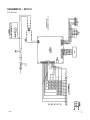
1
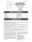
GLASS FRONT MERCHANDISER Covers Models: 3120 – GF12 II 3120A – EC14 3132 – GF19 II 3141 – GF35 II SERVICE MANUAL A10487 December 1998 P/N 4209514 Rev. C TABLE OF CONTENTS INTRODUCTION .......................................... 1 SPECIFICATIONS........................................ 2 Cabinet Inches Metric............................... 2 Glass ......................................................... 2 Electrical.................................................... 2 Capacity .................................................... 2 Pricing ....................................................... 2 UNPACKING & INSTALLATION ................. 2 GROUNDING & ELECTRICAL .................... 3 LOADING PRODUCTS ................................ 3 CHANGING TRAY CONFIGURATION AND RETIMING............................................ 4 Removing and Replacing Trays ................ 4 Changing Timing ....................................... 4 Product pushers..................................... 4 Retiming GF12 II.................................... 5 Retiming GF19 II and GF35 II................ 5 Changing Tray Configuration .................... 5 GF12 II................................................... 5 GF19 II and GF35 II ............................... 5 CONTROLLER FUNCTIONS ....................... 6 Sales Mode ............................................... 6 Service Mode ............................................ 7 Displayed Errors .....................................7 Programming the Controller ...................8 COIN MECHANISM ....................................11 Option Switch Setting...............................11 DOLLAR BILL VALIDATOR.......................12 Removing Accepted Bills .........................13 Troubleshooting .......................................14 Clearing Jams and Cleaning....................14 CARE & CLEANING ...................................14 Cabinet Interior ........................................14 Cabinet Exterior .......................................14 PARTS ORDERING ....................................15 Trays........................................................15 Augers .....................................................15 Procedure ................................................15 To Order by Mail...................................15 To Order by Fax ...................................15 To Order by Phone ...............................15 SCHEMATIC – GF12 II ...............................16 SCHEMATIC – GF19 II ...............................17 SCHEMATIC – GF35 II ...............................18 Record the Model Number and Serial Number of your machine below. The Model and Serial numbers are needed for quick service and parts information for your machine. The numbers are available on the identification plate located on the back of the cabinet of the machine. MODEL NUMBER: __________________________________________________ SERIAL NUMBER: __________________________________________________ ii INTRODUCTION This manual contains instructions, service and installation guidelines for the Glass Front Merchandiser II product line. All Glass Front Merchandisers are equipped with an electronic control system, which includes a wide variety of features that can be programmed and used by the owner/operator as needs arise. All programming of the vend functions, pricing and features is done at the controller. Changes can be made without the need of any additional accessories or remote parts. Cash accountability provisions allow the owner/operator to retrieve information such as "Total Cash" transactions and "Total Vend" cycles that have been performed by the vendor. Electrical malfunctions are recorded by the controller and are displayed when the machine is placed in the Service Mode. This notifies the service person of non-functional motors or selections. The vending sequence is "first-in, first-out" for each selection, eliminating the need for stock rotation to maintain fresh products in the vend area. Each selection has an individual motor and operates independently from other motors. Each vendor can support a “satellite” vending machine, such as a Can Vendor, Food Merchandiser, or Can/Bottle Vendor. Each machine is identified by a model number and a serial number. These identification numbers appear on the Serial Number Plate attached to the inside and rear of the vendor. Record these numbers for your records. All inquires and correspondence pertaining to this vendor should reference the model and serial numbers. It is recommended that this manual be read thoroughly to familiarize the service person with the functions of all components, along with the features that are available. The initial set-up of a vending machine is a very important step of insuring that the equipment operates in a troublefree manner. By following the instructions at the initial installation of the machine, service problems can be avoided and set-up time can be minimized. Should you have any questions pertaining to information in the manual, replacement parts or the operation of the vendor you should contact your local distributor or: VendNet™ P. O. Box 488 165 North 10th Street Waukee, IA 50263-0488 PHONE: PARTS FAX: SALES FAX: USA 1-800-833-4411 USA 1-515-274-3641 INT’L 1-515-987-4447 1-515-274-0390 NOTE In some cases, to attach a satellite vendor a harness adapter will be required. Refer to the satellites Service Manual for additional installation instructions. The satellite vendor utilizes the Glass Front Merchandiser’s controller, coin changer, bill validator (if applicable) and keypad to perform the vend functions they require. 1 SPECIFICATIONS Cabinet UNPACKING & INSTALLATION Inches Height Metric 68 173 cm Depth GF12 II EC14 GF19 II GF35 II 33 1/2 35 1/2 30 1/8 30 1/8 87 cm 90.2cm 76.5 cm 76.5 cm Width GF12 II EC14 GF19 II GF35 II 21 21 28 38 53.3cm 53.3cm 71.1 cm 96.5 cm Weight GF12 II EC14 GF19 II GF35 II Lbs kg 341 350 391 476 155 159 177 216 Glass Use 1/8-inch (3.175 mm) tempered glass only Height Width All GF12 II EC14 GF19 II GF35 II Inches 42.244 9.062 9.062 14.187 24.687 Metric 107.3 23 23 36 62.7 Electrical Power Cycle Current 115 VAC 60 Hz 1 Amp 220 VAC 50 Hz 1 Amp Capacity 80-Select Controller Options: Up to 80 Snack Selections or 60 Snack Selections & 12 Satellite Canned Drink Selections Pricing MDB Coin Mechanism 2 To minimize installation time and to avoid service problems due to improper installation, follow the instructions outlined in this manual. This machine has been thoroughly inspected before leaving the factory. The delivering carrier has accepted this vendor as its responsibility. Any damage or irregularities should be noted at the time of delivery and reported to the carrier. Request a written inspection report from the claims inspector to file any claim for damage. File the claim with the carrier (not the manufacturer) within 15 days after receipt of the machine. Carefully remove the outside packing material in a manner not to damage the finish or exterior of the machine. Inspect the machine for concealed shipping damage. Report any damage hidden by the shipping material directly to the delivering carrier on a hidden damage report. Record the model number and serial number of the vendor for your records. These numbers are on the Serial Plate on the back or inside of the cabinet. Refer to these numbers on all correspondence and inquiries pertaining to this vendor. Remove the "Knock-A-Way" skid boards. Place a 2 x 4 under the vendor, insert a screwdriver or prying tool into the groove of the Knock-A-Way and split it in two. Turn the leveling screws in as far as possible. See Figure 1. Position the vendor no further than nine feet (2.74 meters) from the power outlet or receptacle and check that the door will open fully without interference. Level the vendor, making sure all levelers are touching the floor. The vendor must be level for proper operation and acceptance of coins through the coin mechanism. When the vendor is level, the door can be opened to any position and not move by itself. Try the door half closed, straight out and in a wide-open position. Figure 1B. Testing 115V Outlet LOADING PRODUCTS Figure 1. Removing the Knock-A-Way Skid Boards The keys to the vendor are shipped in the coin return cup. Open the outer door and remove all internal packing material. Consult all local, state and federal codes and regulations before installation of the vendor. GROUNDING & ELECTRICAL Prior to connecting the equipment, the integrity of the main electrical supply must be checked for correct polarity, presence of ground and correct voltage (See Figures 1A and 1B). It is recommended that these checks be repeated at 6month intervals with the routine safety electrical testing of the equipment itself. To correct low voltage, amperage, polarity, or zero ground, consult a licensed electrician. For 230 V vendors, the power source should be 230 VAC (±10%) 50 cycle, with at least a 10 amp dedicated circuit. To load products, lift the tray slightly and pull forward until the tray stops. The upper-most trays of the GF19 II and the GF35 II tilt for ease of loading. All trays tilt on the GF12 II and EC14. NOTE Refer to the GF12 II tray sections for adjusting the EC 14 trays. Load products from front to back, making sure all items fit freely between the augers. Do not attempt to force oversize items or packages into the spaces. Do not skip a space. The bottom of the package should be placed on the bottom of the compartment, above the product augers. The label should face the front of the machine for easy identification by the customer. See Figure 2. When finished loading each tray, make sure the tray is returned to its proper standby position. All trays must be pushed to the rear of the cabinet and properly seated in the "detent" position. For 115 V vendors, the power source should be 115 VAC (±10%) 60 cycle, with at least a 10 amp dedicated circuit. Figure 2. Loading the Tray A10100 Figure 1A. 230V Outlets The size of the item being vended must be larger than the diameter of the auger being used to vend properly. Undersized items could cause vend problems. If the product does not fit the auger properly, use a different auger or change between a snack and a candy tray configuration. 3 CHANGING TRAY CONFIGURATION AND RETIMING Removing and Replacing Trays To remove a tray from the vendor: 1. Pull out the tray to be removed until it stops. 2. Disconnect the tray harness and undo any clamps. See Figure 3. 5. Lift up on the rear of the tray and remove it from the vendor. To replace a tray in the vendor: 6. GF19 II and GF35 II: Place the back of the tray on the rails by placing its rear rollers on the left and right rails and lifting up on the front of the tray as you push it back. GF12 II: Place the back of the tray on the rails and lift up to clear the tray stops. 3. GF19 II and GF35 II: Disconnect the main harness from the tray plug. Slide tray into machine until it stops, lift up slightly on front of tray and push in to lock into detent position. GF12 II: Remove harness from slot in rightside wall and disconnect harness plug. 7. GF19 II and GF35 II: Connect the main harness to the tray plug. 4. Lift up on the front of the tray and pull slightly forward (approximately 1/2 inch/1.5 cm) to clear the tray stop. Re-clamp the main harness if necessary. GF12 II: Connect harness plug. Install harness tubing into slot in right-side wall. 8. Test vend the tray to assure that the tray plug is properly seated and all motors are working. Changing Timing The shape, size and thickness of product affects how well it falls off the tray. If vending problems occur with auger ends at the standard 6 o’clock position, adjust the drop off either with product pushers or by retiming the auger. GF12 II Product pushers Order product pushers. P/N 4025748 Snaps on to end of auger. See Figure 4. Test vend and adjust if necessary. GF19 II & GF35 II Figure 3. Tray Harness Connections 4 Figure 4. Product Pushers Retiming GF12 II 1. Remove the tray from the vendor. GF12 II can be retimed. 2. Pull hair pin clip holding auger to motor hub. 1. Remove the tray from the vendor as previously described. 3. Rotate auger 180º. 2. Remove the two screws from the top of the motor assembly. See Figure 5. 3. Lift up slightly on the motor assembly. 4. Replace hair pin clip through the auger and the motor hub. 5. Replace tray in the vendor 4. Pull the auger away from the motor until the auger hub separates from the motor shaft. Changing Tray Configuration 5. Rotate the auger to the desired position and reinsert the hub into the motor. GF12 II 6. Slide the motor assembly down, locating the tabs in the slots in the bottom of the tray. Be sure the rib in the tray is locked to the tabs of the auger coupling. 7. Reinsert the two screws into the top of the motor assembly. See Figure 5. 8. Replace the tray in the vendor. Order the desired augers. See the Parts Ordering section of this manual. 1. Remove tray from the machine. 2. Remove motor assembly as described in Retiming GF12 II. See Figure 5. 3. Remove augers. 4. If necessary, remove motors from motor assembly. Retain the screws. 5. Move the dividers as necessary. 6. Move motors if necessary. 7. Insert augers. 8. Replace motor assembly as described in Retiming GF12 II. 9. Replace tray in the machine. 10. Test vend new configuration. GF19 II and GF35 II Augers can not be changed, however Snack and Candy trays are interchangeable. Order the desired trays from the Parts Department. See the Parts Ordering section of this manual. Figure 5. GF12 II Motor Mount Assembly Retiming GF19 II and GF35 II GF19 II and GF35II can only be retimed to 12 o’clock (factory set at 6 o’clock) – only useful for very wide products. Use product pushers to retime end of auger. To change from one tray type to the other, the tray side rails must be moved forward or back in slots in side walls. 1. Remove the tray from the machine. 2. Unscrew the screw holding the rail to the side wall. 5 3. Slide the rail forward (for a snack tray) or back (for a candy tray). CONTROLLER FUNCTIONS Sales Mode The Sales Mode is the normal operating mode of the vendor. At the start of a sales cycle, 0.00 displays. If the coin tube level of the mechanism’s lowest denomination is below the lowest sensor, the “USE EXACT CHANGE” LED lights. As money is deposited, the amount of credit displays. NOTE Figure 6. Adjusting a Side Rail 4. Install the screw to hold the rail in place.. 5. Install the replacement tray in the machine. 6. Attach the main harness to the tray plug. 7. Test vend the entire tray. Upon initial power up or reset, - - - displays until the peripherals and the controller have been initialized. The customer presses the desired selection number on the keypad. The selection number displays. The controller compares the established credit with the vend price of that selection. If sufficient credit is available and the selection is present, the vend cycle starts. Following a successful vend, the amount of change to be returned displays for two seconds or until all coinage is paid back. The vend counter is incremented by one and the cash counter is incremented by the price of the selection vended. NOTE Counter rollover occurs at 99,999,999 for the number of vends and $999,999.95 for the total cash sales. 6 If credit is less than the selection price, the price flashes for three seconds or until a new selection key is pressed. If the motor is flagged as faulty, the selection number and the “MAKE ANOTHER SELECTION” LED flash for three seconds or until a new selection key is pressed. If an item is selected and the vendor is unable to complete the vend cycle, the “MAKE ANOTHER SELECTION” LED flashes for three seconds or until a new selection key is pressed. That selection is disabled and remains so until cleared or repaired. The credit is returned. When the credit amount equals or exceeds the highest priced item, the vendor no longer accepts credit. NOTE Credit acceptance is controlled by the coin mechanism. Service Mode To change settings and display diagnostic information, the controller must be placed in the Service Mode. When the controller is placed in the Service Mode, the number of active motors display. If any errors were detected during a vend, the failed motors display next, and then any MDB error codes. See Table 1 for MDB Error Code definitions. NOTE Record the displayed information immediately upon entering the Service Mode. Any keypad input or exiting the Service Mode will erase this data and the MDB error codes. To enter the Service Mode, open the door of the vendor and press the Service Mode Button on the Control Board on the inside of the door. See Figure 7. Figure 7. Service Mode Button Location on Control Board To exit the Service Mode, press the Service Mode Button. The vendor will also exit the Service Mode if there is no key pressed for approximately 25 seconds. If you are in the process of changing data when you exit the Service Mode (either by pressing the Service Mode Button or by allowing the system to time-out) any unsaved changes will be ignored, leaving the data in its previous state. Displayed Errors Motor Configuration Errors NOTE Record the displayed information immediately upon entering the Service Mode. Any keypad input or exiting of the Service Mode will erase this data and the MDB error codes. When the controller is placed in the Service Mode, any errors or failed motors that were detected during a vend will display. The displayed motors were functional when the Sales Mode was last activated, but, due to failures or removal, are not in the circuit now. 7 For instance, if during a vend the controller detected a motor switch failure, that selection would be flagged as faulty and would be disabled. That motor would display the next time the Service Mode is entered. Programming the Controller To access the programming, enter the Service Mode, then choose from the following modes. Table 2. Modes PRESS MDB Errors [ 1 ] NOTE The following errors are only displayed when the Service Mode is entered. Record the displayed information immediately upon entering the Service Mode. Any keypad input or exiting of the Service Mode will erase the MDB error codes. INDICATES CScF Invalid mechanism scale factor tSnS Defective coin tube mechanism CJAM Coin jam detected tJAM Coin tube jam detected CnEr Coin acceptance problem detected AcEr Acceptor unplugged ChEr Coin mechanism ROM checksum bad bScF Invalid acceptor scale factor bSnS Defective bill sensor bJAM Bill jam detected StFL Bill stacker is full CShb Bill cash box is out of position bMtr Bad bill motor detected bLEr Bill acceptor ROM checksum bad rScF Invalid card reader scale factor CdEr Card error detected bCrd Invalid card detected rJAM Card reader jam detected CoEr Communications error detected brdr Card reader failure 8 MODE Coin Dispense Coin [ 2 ] Motor Count [ 3 ] Acct Accountability [ 4 ] Prc Price Setting [ 5 ] Slct Test Vend Single Motor [ 6 ] Test Vend All Motors [ E ] Optn Vend Options [ B ] ºDeg (temperature) Refrigeration Control (not used on this machine) Table 1. Error Codes DISPLAYS DISPLAYS Coin Dispense Mode In the Coin Dispense Mode, coins stored in the coin mechanism payout tubes can be removed. Press the Service Mode Button, then press [ 1 ]. Coin displays. See Table 3. Table 3. Coin Dispense Keys PRESS TO DISPENSE A COIN OF: [ A ] the lowest denomination [ B ] the next higher denomination [ C ] the next higher denomination [ D ] the highest denomination Pressing a key once will pay out one coin. Pushing and holding a key will allow the coins to pay out at a rate of approximately two per second. Coins will continue to be dispensed from the payout tube as long as its activating key is pressed. Pushing any key other than [ A ], [ B ], [ C ] or [ D ] will exit back into the Service Mode. Motor Count Mode Price Setting Mode The Motor Count Mode displays the total number of functional motors configured within the machine. This number should equal the total number of selections. Only the total number of functional motors displays; individual selection numbers do not display. A vend price must be set for each selection. The price programmed must match the desired item and price scroll. To check a price, push the selection numbers while in the Sales Mode. Press the Service Mode Button, then press [ 2 ]. The controller tests each motor in the configuration. If the motor count displayed does not agree with the total number of selections in the machine, the electrical circuit of all motors is not complete. To exit, press the Service Mode Button once. To determine which motor is not functioning: Were faulty motors displayed when placed in the Service Mode? Test vend single selections. Test vend all selections. Refer to the “Troubleshooting” section of this manual for further assistance. Press the Service Mode Button, then press [ 4 ]. Prc displays. NOTE The coin mechanism must be installed to verify the correct price. If the item price is set to .00, the item will vend for free. Press the selection letter and number of the selection you want to price. That selection’s current price displays. To change the price: press [ # ] to decrease the value, or. press [ * ] to increase the value. To save the price displayed: press the selection number of the next item to be priced, Accountability Mode press another function key, or The total vends and total cash are displayed. This information is not resettable. The display will continue to flash the accounting data until the mode is exited. press the Service Mode Button. Press the Service Mode Button, then press [ 3 ]. Acct displays. For the Vend Count, press [ A ]. The first four digits of an eight digit number display. Then, the last four digits will display. NOTE When setting vend prices, make sure the price scrolls on the product shelves agree with the vend prices programmed into the controller and that the selection labels are properly located below the item. For the Cash Total, press [ B ]. The first four digits of an eight digit number display. Then, the last four digits (including any decimal point) display. To exit, press another function key or press the Service Mode Button. 9 Test Vend Single Motor Mode Test Vend All Motors Mode CAUTION: All selections can be tested to verify that they are functioning properly. The controller will check the motor circuits and run each selection, starting with the first motor in the first row. Because this vendor utilizes DC motors, do not attempt to turn the helix manually or damage to the motor could occur. To verify that a selection is functioning properly, the controller will check the motor circuit and try to run the selection through a complete vend cycle. The vend count is not increased. Press the Service Mode Button, then press [ 5 ]. Slct displays. Press the letter and number of the selection to be tested. If the selected motor is operational, the motor will run one complete cycle and the controller will return to the Service Mode. If the selected motor fails, FAiL will display for 2 seconds; then the controller will return to the Service Mode. NOTE Test vending a selection flagged as faulty will reset the flag if the motor successfully completes the vend cycle. Entering and exiting the Service Mode will also reset the flag, even if the motor is non-functional. To exit back to the Sales Mode, press the Service Mode Button once. The operator must observe the testing of the selections, because the controller will skip any motor(s) that was not sensed on the motor circuit prior to beginning the machine test. The accounting data information is not updated in the Test Vend Mode. Press the Service Mode Button, then press [ 6 ]. The selection number of each motor is displayed as it is tested. If the vend is successful, the controller will continue with the next selection. If the vend fails, Fail displays for two seconds. Then the next motor is tested. The test may be stopped at any time by pressing and holding any key on the selection keypad during the test. Doing this returns the program to Service Mode. To exit to the Sales Mode, press the Service Mode Button. Vend Options Mode Various sales options can be enabled and disabled through this option. See Table 4. Press the Service Mode Button, then press [ E ]. Optn displays. To exit the Vend Options Mode, press a different function key, or press the Service Mode Button. 10 Table 4. Vend Options Mode PRESS [ A ] DISPLAYS Fcry = On TO TOGGLE PRESS [ A ] Fcrn = Off [ B ] Escy = On [ B ] nULy = On [ C ] Cany = On [ 2 ] FrEy = On [ D ] Fchy = On Fchn = Off Can Drink Option: Host can run a satellite can drink vendor. Selection motors are configured upon exiting the Service Mode if this option has been changed. Satellite can drink vendor selections are disabled. [ F ] FrEn = Off Multi Vend Option: Multiple purchases can be made as long as adequate credit is available. After 20 seconds of no activity the change will be returned automatically. Customer immediately receives the change after a vend. Cann = Off [ F ] Bill Escrow Option: Returns the bill to the customer when no vend is made and the coin return button is pushed. (Must have a validator with escrow capabilities.) Gives change for bill when the coin return button is pushed. nULn = Off [ D ] Force Vend Option: Purchase necessary to receive change from a paper bill, overriding the "coin return" command. A purchase is not necessary to receive change for a bill insertion. Escn = Off [ C ] DESCRIPTION [ 2 ] Free Vend Option: All product vended at no charge to customer. Individual price settings used. Fast Change Option: Change is returned as soon as a selection is made. Change is returned after a selection is made. COIN MECHANISM Option Switch Setting (Applies to U.S. currency coin mechanisms only) Use the three option switches to select the type of coins to be accepted along with the number of quarters that will be stored in the 25¢ coin tube for overpayment. The coin mechanism option switches have been factory set to OFF. Load the coin mechanism coin tubes with nickels, dimes and quarters. See Figure 8. Table 5. Coin Tube Capacity 5¢ 10¢ 25¢ OPTION HI 25¢ LOW 25¢ FULL LEVEL 68-69 98-99 66-67 8-9 LOW LEVEL 7-8 10-11 8-9 8-9 To change settings: Turn the power switch OFF. Remove the coin acceptor (upper section) portion of the coin mechanism. See Figure 9. The coin mechanism pays out nickels, dimes and quarters from self-loading, high capacity change tubes in the least number of coins available. CAUTION: Do not plug or unplug coin mechanism with the power on! 11 Figure 9. Option Switches and Power Light Figure 8. Coin Tube Location in Coin Mech. NOTE The bill validator operation of this vendor requires the “LO 25¢” option switch to be in the “Hi” or “OFF” position. The controller will monitor the condition of the coin mechanism at all times. Any activity (coins inserted) will be recorded. Locate the coin mechanism option dip switches and select from the following settings: Table 6. Coin Mech Option Switches SWITCH ON OFF 1 USA/CAN U.S. and Canadian coins accepted Canadian coins rejected 2 LO 25¢ Quarters diverted to the cash box after the change tube contains approximately 8 quarters Quarters diverted into the quarter tube until it is full 3 $ ACPT Dollar coins accepted Dollar coins rejected DOLLAR BILL VALIDATOR (Available in certain U.S. currency markets only) The BA32SA bill validator contains an option switch module allowing the unit to be customized to the requirements of an individual account. All validators shipped from the factory will be set with switches #3 & #8 in the “ON” position. All other switches will be set to the “OFF” position. See Table 7. 12 Table 7. Validator Option Switches SWITCH ON OFF 1 High Security Standard Acceptance 2 Accepts bills in one direction only (face up, green seal first) Accepts bills in both directions (face up) 3 Serial or Parallel Interface Pulse interface 4 Accept $20 Reject $20 5 Accept $10 Reject $10 6 Accept $5 Reject $5 7 Accept $2 Reject $2 8 Accept $1 Reject $1 If you want settings different from those set at the factory, follow the steps outlined below: Turn off the power switch in the center right side of the cabinet. See Figure 10. Figure 11. Validator Switch Module Removing Accepted Bills Accepted bills may be removed by opening the “bill box” lid or by removing the bill box from the validator. See Figure 12. NOTE Figure 10. Main Power Switch Location If the bill box is removed, make sure that it is fully latched in place when it is returned to the validator. WARNING: To avoid electrical shock, always disconnect the power before performing service. Remove the retaining screw that secures the logic board and strain relief. See Figure 11. Slide the logic board downward to expose the option switch module. Set the option switches to the desired setting. Figure 12. Removing the Bill Box 13 CAUTION: Troubleshooting To troubleshoot, read the flashes or blinks of light from the red LED located on the side of the logic board cover. These flashes can be seen through the grey smoked cover. See Figure 13. During normal operation the LED will be a steady or constant red. Do not use any petroleum based cleaning solvents, scouring pads or stiff brushes for cleaning. Figure 14. Removing the Bill Box and Lower Housing Figure 13. Validator LED Location Table 8. Validator Diagnostic Codes NO. OF FLASHES No Light DESCRIPTION Check Power And Harnessing To Validator CAUTION: Always disconnect power source before cleaning. 1 Bill Box Full 2 Bill Box Lid is open or not latched in place. Cabinet Interior 3 Check Bill Path 4 All Bill Accept Switches are Off 5 Bill Jam or Sensor Error Wash with a mild detergent and water, rinse and dry thoroughly. Eliminate odors by including baking soda or ammonia in the cleaning solution. Plastic parts may be cleaned with a quality plastic cleaner. Do not get the cleaning solution on electrical components. 6 or more Reset (Remove and Apply Power) or service required. Clearing Jams and Cleaning Trapped bills, debris or dirt can result in poor bill acceptance or bill rejection. Remove the “bill box” and lower housing to clear trapped bills or debris. See Figure 14. Clean the bill path plastic parts or belts with a cloth moistened with a mild soap and water solution. Clean the magnetic head and optic sensors using a swab and isopropyl alcohol. 14 CARE & CLEANING Cabinet Exterior Wash with a mild detergent and water, rinse and dry thoroughly. Clean occasionally with a quality car wax. • • • • • PARTS ORDERING Trays Table 9. GF19II and GF35II Trays MACHINE SIZE TRAY GF19 II GF35 II P/N Candy 1211163 Snack 1211164 Candy 1212293 Snack 1212295 Augers Table 10. GF12 II Auger Sizes Available PRODUCT Type PART NUMBER All orders are carefully packed and inspected prior to shipment. Damage incurred during shipment should be reported at once and a claim filed with the terminating carrier. If you do not have the right parts manual, contact the Parts Department. They will provide a copy for you, if available. Do not wait to order until you receive the parts manual; instead use the most accurate description you can. Include the model number and serial number of the machine, the name of the assembly in which the part is used, and if practical, a sample part. Furnish any information to enable our Parts Department to pinpoint the exact part needed. Width Thick Qty 2-3/4 1-3/16 15 4200272-000 C 2-3/4 15/16 18 4200272-001 A 2-3/4 21/32 24 4200272-002 N 2-3/4 1/2 30 4200272-003 D 2-3/4 1-1/2 12 4200272-004 Y 2-3/4 2-1/32 9 4200272-005 2-3/4 3-3/32 6 4200272-006 S 5-1/2 1-13/16 10 4200272-007 N 5-1/2 1-1/2 12 4200272-008 A 5-1/2 1-3/16 15 4200272-009 C 5-1/2 2-11/16 7 4200272-010 To Order by Fax K 5-1/2 2-5/8 8 4200272-011 1-515-987-4447 Procedure When ordering parts, include the following: • • • Vendor Model Number Vendor Serial Number Shipping and Billing Address Preferred Method of Shipment Customer Account Number Quantity Required Part Number Description of part NOTE When “Right” and “Left” are used with a part name, it is taken to mean that the person is facing the machine with the door closed. To Order by Mail VendNet™ P. O. Box 488 165 North 10th Street Waukee, IA 50263-0488 To Order by Phone USA 1-800-833-4411 Canada 1-800-858-4730 Other locations 1-515-274-3641 If you have any questions, check out our Website http:\\www.vendnetusa.com or please call VendNet. Ask for the Parts Department. E-Mail: [email protected] 15 SCHEMATIC – GF12 II P/N 4209903 16 SCHEMATIC – GF19 II P/N 4209904 17 SCHEMATIC – GF35 II P/N 4209617 18