1
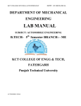
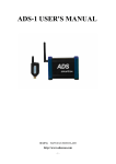
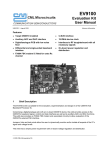
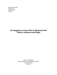
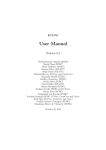
PURE BRAKE
®
Brake-Fluid Exchanger
OPERATION MANUAL
Read All Operating Instructions Before Use
MODEL #1000 MER
U.S. Patent No. 6,206,055
PART# 98119
rev 05/10
INDEX
Advisories (Warnings) . . . . . . . . . . . . . . . . . . . . . . . . . . . . . . . . . . . . . . . . . . . . . . . . . . . . . . . . . .1
Safety Requirements
Precautions
Packaged With Your Machine . . . . . . . . . . . . . . . . . . . . . . . . . . . . . . . . . . . . . . . . . . . . . . . . . . . .2
Machine Specifications . . . . . . . . . . . . . . . . . . . . . . . . . . . . . . . . . . . . . . . . . . . . . . . . . . . . . . . . .3
Specifications
Starting The Service . . . . . . . . . . . . . . . . . . . . . . . . . . . . . . . . . . . . . . . . . . . . . . . . . . . . . . . . . . . 4
Defining Service Descriptions
Access Code . . . . . . . . . . . . . . . . . . . . . . . . . . . . . . . . . . . . . . . . . . . . . . . . . . . . . . . . . . . . . . . . . .5
Access Code
Incorrect Code Entries
Getting Started . . . . . . . . . . . . . . . . . . . . . . . . . . . . . . . . . . . . . . . . . . . . . . . . . . . . . . . . . . . . . . . . 6
Procedure For Connecting The Machine
Performing The Service . . . . . . . . . . . . . . . . . . . . . . . . . . . . . . . . . . . . . . . . . . . . . . . . . . . . . . . . .8
Quick-Service Procedure
Manual-Service Procedures
OEM-Service Procedures
Draining The Fluid Tank . . . . . . . . . . . . . . . . . . . . . . . . . . . . . . . . . . . . . . . . . . . . . .19
Procedure For Draining The Used-Fluid Tank
Adapter Identification . . . . . . . . . . . . . . . . . . . . . . . . . . . . . . . . . . . . . . . . . . . . . . . . . . . . . . . . . 20
Replacement-Parts List . . . . . . . . . . . . . . . . . . . . . . . . . . . . . . . . . . . . . . . . . . . . . . . . . . . . . . . .22
Getting Help . . . . . . . . . . . . . . . . . . . . . . . . . . . . . . . . . . . . . . . . . . . . . . . . . . . . . . . . . . . . . . . . .25
PURE BRAKE® MANUAL
PART# 98119
rev 05/10
ADVISORIES
SAFETY REQUI REM ENTS:
• Safety goggles and gloves should be worn during the entire servicing of the vehicle.
• Never raise a vehicle when it is occupied.
• Always verify that the car is operating correctly and has the parking brake set before starting
a brake service.
• Perform all repairs and maintenance procedures before starting a service. Inspect the vehicle
for fluid leaks, damaged belts, damaged hoses and engine noise or unsafe conditions.
PRECAUTION S:
This equipment is designed to be used only with brake fluid supplied by an authorized
distributor.
Before starting a service, inspect the equipment for damage to; hoses, adapters or display
system. Repairs to the system must be completed before the equipment can be used.
Cover all painted surfaces with fender covers before starting the service.
When lifting a vehicle, always verify that all safety locks and precautions are followed to the
manufacturer’s specifications.
PURE BRAKE® MANUAL
1
PART# 98119
rev 05/10
PA C K A G E D W I T H Y O U R M A C H I N E
• A standard set of Master-Cylinder Adapters (see page 21 for list).
• Waste-storage container (located in the front storage area of the Chassis).
• Fluid extractor with valve.
• Lookup OEM manual / operation manual.
Fluid Extractor
Waste Container
PURE BRAKE® MANUAL
2
PART# 98119
rev 05/10
M A C H I N E S P E C I F I C AT I O N S
SPECI FICATION S:
Dimensions:
Weight:
Chassis:
Power:
Used Fluid Capacity:
38.5" H x 18.5" W x 24" D
80 lbs. w/adapters
Linear low-density Polyethylene
12V DC - 15 Amps max (non-polarity-sensitive)
5 Gallons
Machine Dimensions:
18.5"
24"
38.5"
PURE BRAKE® MANUAL
3
PART# 98119
rev 05/10
STARTING THE SERVICE
THE FOLLOWING ITEM WILL BE NEEDED TO PERFORM THE SERVICE:
• One bottle of Brake Fluid (Depending on the vehicle fluid requirements);
- Heavy-Duty DOT 3 Brake Fluid.
- Premium Plus DOT 4 Brake Fluid.
• Locate the proper master-cylinder adapter. (See Page 20, Adapter-identification Chart)
• A line wrench that will fit the bleeder valves.
• Safety glasses must be worn at all times.
• Gloves must be worn at all times.
• Fender covers must be placed to protect all painted surfaces.
DEFI N I NG SERVICE DESCRI PTION S:
QUICK-SERVICE MODE – The Quick-Service Mode will simultaneously remove fluid from all
four wheel cylinders as fluid is being supplied to the Master Cylinder, resulting in a service
that is only 10-12 minutes long and removes virtually all of the old fluid.
MANUAL MODE – The technician operating the Pure Brake® Machine can operate the unit
as a single-draw machine, turn off and on the pressure and vacuum at any time, having full
control of the operation at all times for bleeding brake systems.
OEM SERVICE – The Pure Brake® Machine will flush the vehicle’s brake system using the
recommended bleeding sequences recommended by the OEM (Original Equipment
Manufacturer).
PURE BRAKE® MANUAL
4
PART# 98119
rev 05/10
ACCESS CODE
ACCESS CODE:
The Pure Brake® Machine utilizes an “Access-Code” system to activate the machine
before it can be used to service vehicle brake systems. The access codes are located on
the front of each bottle of brake fluid.
- Heavy-Duty DOT 3 Brake Fluid.
- Premium Plus DOT 4 Brake Fluid.
(Ask your representative for more information.)
Once a code has been entered into the machine, it will allow up to fifty (50) minutes for the
service to be completed (average services will only take 7-10 minutes). If the service is not
completed in the allotted time, the machine will indicate an error has occurred and will stop
the service. The used code will not reactivate the machine. To reactivate the machine, a
new code from a new bottle will need to be entered.
I NCORRECT CODE ENTRI ES:
The Pure Brake® Machine will allow a maximum of twelve (12) incorrect codes to be
entered per day. After the twelfth incorrect code is entered during a calendar day, the
machine will become disabled.
To reactivate the machine, you will be required to enter a password. The passwords can
only be obtained by reaching Equipment Technical-Service at (866) 244-6621, from 7:00 am 3:30 P.M. PST. When you call, you will be asked to supply the technician with the following
information:
- The system code from the machine’s display screen.
- The serial number of the machine (located below the handle).
- The location of the store.
- A phone number where the operator of the machine can be reached.
Once the password is entered, the machine will reset and be ready for use.
NOTE: AFTER ENTERING A FEW WRONG PASSWORDS, THE MACHINE WILL LOCK AND WILL REQUIRE
A VISIT FROM ONE OF OUR TECHNICIANS TO REPROGRAM THE MACHINE.
PURE BRAKE® MANUAL
5
PART# 98119
rev 05/10
G E T T I N G S TA R T E D
PROCEDURE FOR CON N ECTI NG TH E MACH I N E:
STEP 1 - S AF ETY
Ensure that the vehicle's engine is off, and that the parking brake has been securely set.
Inspect the vehicle for leaks and any damaged hoses or belts. Make any repairs prior to
exchanging/flushing brake fluid. Place fender covers over any painted surfaces close to the
master cylinder area, and where any hoses may hang over the fender or come in contact with
the vehicle. Safety glasses and gloves should be worn during the service.
STEP 2 - B RAKE S YSTE M I N S P ECTION
Inspect the master cylinder for leaks, cracks or any other damage. Note the condition and
level of the brake fluid prior to starting the service. If empty, read the following note.
NOTE: IF THE MASTER CYLINDER IS EMPTY DO NOT START A SERVICE. AIR MAY HAVE ENTERED THE
BRAKING SYSTEM OF THE VEHICLE. FOLLOW THE MANUFACTURES RECOMMENDED BLEEDING
PROCEDURE AND METHODS BEFORE CONTINUING WITH THE SERVICE.
STEP 3 - I DE NTI FY T H E C OR R ECT B RAKE F LU I D
Use the vehicle’s owner manual, or the vehicle’s “under hood” Brake-Information Sticker, to
identify which type of fluid is required for the vehicle’s brake system. If the vehicle brake
system requires DOT 3 brake fluid, use Heavy-Duty Brake Fluid DOT 3. If the vehicle
brake system requires DOT 4 brake fluid, use Premium Plus Brake Fluid DOT 4.
The Pure Brake® Machine will not perform services on vehicles requiring DOT 5, Hydraulic
System Mineral Oil (HSMO), or any other type of brake fluid.
STEP 4 - ATTACH T H E B OTTLE TO T H E M ACH I N E
Remove the cap and the foil seal from the bottle. Insert the pickup-tube assembly into the
new bottle of brake fluid and secure it with the pick-up-tube ring. Place the bottle into the
tray on the front of the machine.
PURE BRAKE® MANUAL
6
PART# 98119
rev 05/10
G E T T I N G S TA R T E D
STEP 5 - P OWE R I NG -U P T H E U N IT
Attach both of the black battery clamps to a 12V DC power supply (preferably the vehicle’s
12V DC battery). Do not use a battery charger to power the machine. If the bottle has
not been installed, at this time the machine will require that you do so.
Once the Pure Brake® Machine is powered-up, the system will automatically start a
self-diagnostic test. If the machine does identify a system error, the system will give a warning
and inform the user. The machine will not operate until the problem has been corrected
(see the Getting-Help section, page 26, if an error code is found).
STEP 6 - S TART T H E S E RVICE
Once the Pure Brake® Machine has completed the selftest, the unit will display the option to start the service.
FULL INSTRUCTIONS – Step-by-step on-board instructions
requiring the technician to use the next button to
verify the service is completed correctly.
Start a service
1- Full Instructions
2- Min. Instructions
MINIMUM INSTRUCTIONS – For use by technicians that
already know what steps need to be performed and
just need to start the service without the hookup
instruction.
STEP 7 - E NTE R T H E ACCE SS C ODE
The display to the right will show up and you will
be asked to enter the eight-digit access code. The
eight-digit access code is located at the top of the
label on the brake fluid bottle. Enter the code to
activate the machine. Once the code has been
entered, the machine will be activated for fifty (50)
minutes, and the code will no longer be valid. The
system will require a new code from a new bottle in
order to reactivate the machine.
Enter access code
________
BACK
ENTER
RESET
NOTE: SEE PAGE 5 FOR MORE INFORMATION REGARDING THE ACCESS-CODE SYSTEM.
PURE BRAKE® MANUAL
7
PART# 98119
rev 05/10
P E R F O R M I N G T H E S E RV I C E
Once the access code has been entered into the Pure
Brake® Machine, the display will read:
The unit will allow for one of the following services to
be performed:
1 Quick Ser vice
2 Manual Ser vice
3 OEM Ser vice
• QUICK SERVICE – For procedure see below steps 1-11
• MANUAL SERVICE – For procedures see page 12 steps 1-9
• OEM SERVICE – For procedures see page 15 steps 1-12
ESC
NOTE: ALL THREE OF THE SERVICE PROCEDURES (QUICK SERVICE, MANUAL SERVICE, AND OEM
SERVICE) WILL REQUIRE STEPS 1-7 OF THE GETTING-STARTED SECTION TO BE PERFORMED BEFORE
CONTINUING WITH THE SERVICE PROCEDURES.
QUICK-SERVICE PROCEDURE:
STEP 1 - S E LECT Q U ICK S E RVICE
To perform a “Quick Service,” press the number-1 button on the face panel of the unit.
STEP 2 - D RAI N I NG T H E M ASTE R C YLI N DE R
Remove the cap and any filter strainers that might be in the Brake-Fluid Reservoir. Attach
the extraction tool to the suction hose (the suction hose can be identified by the red
color-coded sleeve). Once the extraction tool has been installed, press the “Start” button.
Place the tip of the extraction tool into the master-cylinder reservoir. Squeeze the trigger to
start the removal of the used fluid (in some cases, not all of the used fluid will be
accessible to be removed). Once you have removed most of the fluid from the reservoir,
press the “Stop” button, and then the “Next” button to proceed to the next step.
[START] – Will start the vacuum pump.
[NEXT] – Will skip the draining process and will bring you to step 3.
PURE BRAKE® MANUAL
8
PART# 98119
rev 05/10
P E R F O R M I N G T H E S E RV I C E
STEP 3 - ATTACH T H E A DAPTE R
Locate the correct adapter by using the adapter chart (see pages 20 and 21). Attach the
correct adapter to the vehicle. Once this is completed press the “Next” button to proceed.
[HELP] – Will refer you to the adapter list.
[NEXT] – Will proceed to the next step.
[ESC] – Will bring you back to the select-service screen.
NOTE: WHEN INSTALLING RESERVOIR ADAPTERS WITH A TIE-DOWN CHAIN, BE SURE THAT ALL WIRES,
SENSORS, BRAKE LINES AND HOSES ARE CLEAR OF THE CHAIN'S LOOPS GOING AROUND THE MASTER
CYLINDER, BEFORE TIGHTENING THE ADAPTER IN PLACE.
STEP 4 - ATTACH I NG T H E S E RVICE H OS E
The screen will direct the user to attach the service
hose with the black color-coded sleeve to the
Reservoir Adapter. Once the hose has been
attached, verify that the coupler is properly engaged
onto the adapter. Once this is completed, press the
“Next” button to proceed to the leak test.
Attach the BLACK
service hose and
install adapter
ESC
NEXT
[NEXT] – Will proceed to the next step.
[ESC] – Will bring you back to the select-service
screen.
STEP 5 - L EAK T E ST
The screen will direct the user to begin the leak test
by pressing the “Start” button. During the leak test,
the Pure Brake® Machine will fill the master cylinder
and purge any air from the service hoses and the
master-cylinder reservoir.
Once the brake system is filled, the unit will pressurize
the brake system for 45 seconds, allowing the
technician to inspect the adapters and hoses for any
leaks. Immediately Press the “Stop” button if a
leak is found. Correct any leak by readjusting the
adapter or reconnecting the supply hose to the adapter.
Press the “Start” button to restart the leak test.
PURE BRAKE® MANUAL
9
Press start to begin
leak test
START
ESC
Leak test started
check for leaks
press stop if found
STOP
PART# 98119
rev 05/10
P E R F O R M I N G T H E S E RV I C E
NOTE: IF THE LEAK TEST FAILS, THE MACHINE WILL RESET THE TIME FOR A FIFTY (50) MINUTE FLUSH FROM
THIS POINT, GIVING YOU SOME EXTRA TIME TO FIX THE LEAK.
NOTE: IF A PROPER SEAL CANNOT BE MADE USING A VEHICLE-SPECIFIC ADAPTER, IT MAY BECOME
NECESSARY TO USE ONE OF THE THREE UNIVERSAL ADAPTERS. REMOVE ALL OF THE STORED HOSES
AND POWER CABLE FROM THE MACHINE BEFORE RAISING THE VEHICLE.
[HELP] – Will begin the leak test.
[STOP] – Will stop the leak test to allow the user to correct any leaks and then restart the test.
[ESC] – Will bring you back to the select-service screen.
[BYPASS] – After Checking for leaks, performing any needed repairs, and the Pure Brake
Machine is still failing “leak check” you have the option to “BYPASS” the LEAK TEST MODE.
STEP 6 - ATTACH I NG T H E W H E E L -C YLI N DE R A DAPTE R S
Place the machine so that it is located between the two
axles. The machine should be facing to the rear. The
screen will direct the user to attach the wheel-cylinder
adapters and the hoses to the wheel cylinder’s bleed
screws. The wheel-cylinder adapters are all color-coded
indicating to which wheel cylinder they are to be
attached. The following information can also be
accessed by pressing the “Help” button on the screen.
System is ready for
service. Attach
hoses to wheel cyl's.
NEXT CANCEL
HELP
Hose-Adapters Installation Guide.
The
The
The
The
Yellow Hose Adapter
Green Hose Adapter
Blue Hose Adapter
White Hose Adapter
= (RF)
= (LF)
= (RR)
= (LR)
Right-Front Wheel Cylinder
Left-Front Wheel Cylinder
Right-Rear Wheel Cylinder
Left-Rear Wheel Cylinder
Attach the wheel-cylinder adapters to the vehicle’s correct wheel cylinder as described
above. Press the “Next” button to continue.
[HELP] – Will bring up the online adapter list.
[NEXT] – Will proceed to the next step.
[ESC] – Will bring you back to the select-service screen.
STEP 7 - O P E N I NG T H E B LE E D S CR EWS
Now that the wheel-cylinder adapters are attached, the wheel-cylinder bleed screws will
need to be opened approximately ¼ of a turn. Press the “Next” button to continue.
[NEXT] – Will proceed to the next step.
[ESC] – Will bring you back to the attach-wheel-cylinder-adapter screen (Step #6).
PURE BRAKE® MANUAL
10
PART# 98119
rev 05/10
P E R F O R M I N G T H E S E RV I C E
STEP 8 - T H E F LU S H
The screen will direct the user to press the “Start” button to begin the service. Once the
service has started, inspect the lines attached to the wheel cylinders for flow and color of
fluid being removed. Fluid should be flowing through all four hoses at this time. If fluid is not
flowing through all the hoses, it may be an indication that the bleed screw is blocked; open
the bleed screw by not more than ½ a turn. If fluid will still not flow through the bleed screw,
press the “Pause” button and repair or replace the bleed screw. After the repair is complete,
press the “Resume” button to continue or, if necessary, you can cancel the service.
NOTE: CANCELING A SERVICE DOESN’T RESET THE SERVICE TIME.
After the Pure Brake® Machine has performed a “Pulse Flush,” the unit will instruct the
user to close the bleed screws in the following order:
1. Front-left bleed screw
2. Front-right bleed screw
3. Rear-left bleed screw
4. Rear-right bleed screw
After all of the bleed screws have been closed, remove the hoses from the wheel cylinders.
Once the service is complete, the system will automatically remove the pressure from the
Brake-Fluid Reservoir.
NOTE: LOWER THE VEHICLE BEFORE CONTINUING.
[PAUSE] – Will stop the service to allow the user to correct leaks.
[NEXT] – Will proceed to the next step.
STEP 9 - T E STI NG T H E B RAKE P E DAL
The display will instruct the user of the equipment to push down on the brake pedal and
check if the pedal is firm and is operating correctly.
STEP 10 - R E MOVI NG T H E B RAKE -F LU I D -R E S E RVOI R A DAPTE R
Remove the adapter from the Brake-Fluid Reservoir and press the “Next” button.
STEP 11 - A DJ U STI NG T H E F LU I D L EVE L
To add fluid, press the “Add” button; to remove fluid, press the “Remove” button. After the fluid
level is at the proper level, press the “Next” button. The service is now complete. Remove the
battery clamps from the power supply, and reinstall the Brake-Fluid-Reservoir Cap.
PURE BRAKE® MANUAL
11
PART# 98119
rev 05/10
P E R F O R M I N G T H E S E RV I C E
MAN UAL-SERVICE PROCEDURE:
STEP 1 - S E LECT M AN UAL S E RVICE
To perform a “Manual Service,” press the number-2 button on the face panel.
STEP 2 - D RAI N I NG T H E M ASTE R C YLI N DE R
Remove the cap and any filter strainers that might be in the Brake-Fluid Reservoir. Attach
the extraction tool to the suction hose (the suction hose can be identified by the red
color-coded sleeve). Once the extraction tool has been installed, press the “Start” button.
Place the tip of the extraction tool into the Master-Cylinder Reservoir. Squeeze the trigger
to start the removal of the used fluid (in some cases, not all of the used fluid will be accessible
to be removed). Once you have removed most of the fluid from the reservoir, press the
“Stop” button, and then the “Next” button to proceed.
[START] – Will start the vacuum pump.
[NEXT] – Will skip the draining process and will bring you to step 3.
STEP 3 - ATTACH T H E A DAPTE R
Locate the correct adapter by using the adapter chart (see page 20 and 21) or by using the
online “Help” button. Attach the correct adapter to the vehicle. Once this is completed, press
the “Next” button to proceed.
[Help] – Will refer you to the adapter list.
[Next] – Will proceed to the next step.
[ESC] – Will bring you back to the select-service screen (Step #1).
STEP 4 - ATTACH I NG T H E S E RVICE H OS E
The screen will direct the user to attach the service
hose with the black color-coded sleeve to the
Master-Cylinder Adapter. Once the hose has been
attached, verify that the coupler is properly engaged
onto the adapter. Once this is completed, press the
“Next” button to proceed to the leak test.
Attach the BLACK
service hose and
install adapter
ESC
NEXT
[NEXT] – Will proceed to the next step.
[ESC] – Will bring you back to the selectservice screen.
PURE BRAKE® MANUAL
12
PART# 98119
rev 05/10
P E R F O R M I N G T H E S E RV I C E
STEP 5 - L EAK T E ST
The screen will direct the user to begin the leak test
by pressing the “Start” button. During the leak test,
the Pure Brake® Machine will fill the master cylinder
and purge any air from the service hoses and the
Master-Cylinder Reservoir.
Once the brake system is filled, the unit will pressurize
the brake system for 45 seconds, allowing the
technician to inspect the adapters and hoses for any
leaks. Immediately Press the “Stop” button if a
leak is found. Correct any leak by readjusting the
adapter, or reconnecting the supply hose to the adapter.
Press the “Start” button to restart the Leak Test.
Press start to begin
leak test
START
ESC
Leak test started
check for leaks
press stop if found
STOP
NOTE: IF A PROPER SEAL CANNOT BE MADE USING A VEHICLE-SPECIFIC ADAPTER, IT MAY BECOME
NECESSARY TO USE ONE OF THE THREE UNIVERSAL ADAPTERS.
[HELP] – Will begin the leak test.
[STOP] – Will stop the leak test to allow the user to correct any leaks and then restart the test.
[ESC] – Will bring you back to the select-service screen.
[BYPASS] – After Checking for leaks, performing any needed repairs, and the Pure Brake
Machine is still failing “leak check” you have the option to “BYPASS” the LEAK TEST MODE.
STEP 6 - ACTIVATI NG T H E VACU U M L I N E S
Once the leak test is completed, the system will then allow you to manually activate the
service hoses. Select the hose that you will be working with by pressing the number 1 and
2, then press the “Start” button to activate the vacuum pump and the supply pump.
[#1] – Will turn off/on the vacuum supply to the blue hose.
[#2] – Will turn off/on the vacuum supply to the white hose.
[DONE] – Will complete the service.
[START/STOP] – Will turn off the pumps.
[ESC] – Will return you to the select-service screen.
Press the “Done” button when the service is complete. The system will automatically
release the pressure from the master cylinder.
PURE BRAKE® MANUAL
13
PART# 98119
rev 05/10
P E R F O R M I N G T H E S E RV I C E
NOTE: LOWER THE VEHICLE BEFORE CONTINUING.
STEP 7 - T E STI NG T H E B RAKE P E DAL
The display will instruct the user of the equipment to push down on the brake pedal and
check if the pedal is firm and is operating correctly.
STEP 8 - R E MOVI NG T H E B RAKE -F LU I D -R E S E RVOI R A DAPTE R
Remove the adapter from the Brake-Fluid Reservoir and press the “Next” button.
STEP 9 - A DJ U STI NG T H E F LU I D L EVE L
To add fluid, press the “Add” button; to remove fluid, press the “Remove” button. After the
fluid level is at the proper level, press the “Next” button. The service is now complete. Remove
the battery clamps from the power supply, and reinstall the Brake-Fluid-Reservoir Cap.
PURE BRAKE® MANUAL
14
PART# 98119
rev 05/10
P E R F O R M I N G T H E S E RV I C E
OEM-SERVICE PROCEDURE:
STEP 1 - S E LECT OEM S E RVICE
To perform an “OEM Service,” press the number-3 button on the face panel.
STEP 2 - E NTE R I NG T H E OEM-P ROCE DU R E N U M B E R
The screen will request the user to enter an OEM-Procedure Code. The OEM Codes are
located in the Brake-System-Bleeding-Sequence Guide, P/N 89021. Locate the specific
vehicle the service is to be performed on in the guide, and enter the appropriate procedure
number into the Pure Brake® Machine. The system will require you to confirm your selection.
STEP 3 - D RAI N I NG T H E M ASTE R C YLI N DE R
Remove the cap and any filter strainers that might be in the Brake-Fluid Reservoir. Attach
the extraction tool to the suction hose (the suction hose can be identified by the red
color-coded sleeve). Once the extraction tool has been installed, press the “Start” button.
Place the tip of the extraction tool into the Master-Cylinder Reservoir. Squeeze the trigger
to start the removal of the used fluid (in some cases, not all of the used fluid will be
accessible to be removed). Once you have removed most of the fluid from the reservoir,
press the “Stop” button, and then the “Next” button to proceed.
[START] – Will start the vacuum pump.
[NEXT] – Will skip the draining process and will bring you to step 5.
STEP 4 - ATTACH T H E A DAPTE R
Locate the correct adapter by using the adapter chart (see page 20 and 21) or by using the
online “Help” button. Attach the correct adapter to the vehicle. Once this is completed, press
the “Next” button to proceed.
[HELP] – Will refer you to the adapter list.
[NEXT] – Will proceed to the next step.
[ESC] – Will bring you back to the select-service screen.
PURE BRAKE® MANUAL
15
PART# 98119
rev 05/10
P E R F O R M I N G T H E S E RV I C E
STEP 5 - ATTACH I NG T H E S E RVICE H OS E
The screen will direct the user to attach the service
hose with the black color-coded sleeve to the
reservoir adapter. Once the hose has been attached,
verify that the coupler is properly engaged onto the
adapter. Once this is completed, press the “Next”
button to proceed to the leak test.
Attach the BLACK
service hose and
install adapter
ESC
NEXT
[NEXT] – Will proceed to the next step.
[ESC] – Will bring you back to the selectservice screen.
STEP 6 - LEAK TEST
The screen will direct the user to begin the leak test
by pressing the “Start” button. During the leak test,
the Pure Brake® Machine will fill the master cylinder
and purge any air from the service hoses and the
Master-Cylinder Reservoir.
Once the brake system is filled, the unit will pressurize
the brake system for 45 seconds, allowing the
technician to inspect the adapters and hoses for any
leaks. Immediately Press the “Stop” button if a
leak is found. Correct any leak by readjusting the
adapter, or reconnecting the supply hose to the adapter.
Press the “Start” button to restart the leak test.
Press start to begin
leak test
START
ESC
Leak test started
check for leaks
press stop if found
STOP
NOTE: IF THE LEAK TEST FAILS, THE MACHINE WILL RESET THE TIME FOR A FIFTY (50) MINUTE FLUSH FROM
THIS POINT; GIVING YOU SOME EXTRA TIME TO FIX THE LEAK.
NOTE: IF A PROPER SEAL CANNOT BE MADE USING A VEHICLE-SPECIFIC ADAPTER, IT MAY BECOME
NECESSARY TO USE ONE OF THE THREE UNIVERSAL ADAPTERS.
[HELP] – Will begin the leak test.
[STOP] – Will stop the leak test to allow the user to correct any leaks and then restart the test.
[ESC] – Will bring you back to the select-service screen.
[BYPASS] – After Checking for leaks, performing any needed repairs, and the Pure Brake
Machine is still failing “leak check” you have the option to “BYPASS” the LEAK TEST MODE.
PURE BRAKE® MANUAL
16
PART# 98119
rev 05/10
P E R F O R M I N G T H E S E RV I C E
STEP 7 - ATTACH I NG T H E W H E E L -C YLI N DE R A DAPTE R S
The screen will direct the user to attach the wheelcylinder adapters and the hoses to the wheel cylinder’s
bleed screws. The wheel-cylinder adapters are all
color-coded indicating to which wheel cylinder they are
to be attached. The following information can also be
accessed by pressing the “Help” button on the screen.
System is ready for
service. Attach
hoses to wheel cyl's.
NEXT CANCEL
HELP
WARNING: WHEN YOU ARE USING THE PURE BRAKE® UNIT IN THE OEM MODE,
YOU MUST REFERENCE THE HOSES TO THE PROPER BLEED POINT BY USING THE
HELP OPTION. THE BLEED POINTS WILL CHANGE IN DIFFERENT CODES.
Hose-Adapters Installation Guide
The
The
The
The
Yellow Hose Adapter
Green Hose Adapter
Blue Hose Adapter
White Hose Adapter
= (RF)
= (LF)
= (RR)
= (LR)
Right-Front Wheel Cylinder
Left-Front Wheel Cylinder
Right-Rear Wheel Cylinder
Left-Rear Wheel Cylinder
Attach the wheel-cylinder adapters to the vehicle’s correct wheel cylinder as described
above. Press the “Next” button to continue.
[HELP] – Will bring up the online adapter list.
[NEXT] – Will proceed to the next step.
[ESC] – Will bring you back to the select-service screen.
STEP 8 - O P E N I NG T H E B LE E D S CR EWS
Now that the wheel-cylinder adapters are attached, the wheel-cylinder bleed screws will
need to be opened approximately ¼ of a turn. Press the “Next” button to continue.
[NEXT] – Will proceed to the next step.
[ESC] – Will bring you back to the attach-wheel-cylinder-adapter screen (Step #7).
PURE BRAKE® MANUAL
17
PART# 98119
rev 05/10
P E R F O R M I N G T H E S E RV I C E
STEP 9 - T H E F LU S H
The screen will direct the user to press the “Start” button to begin the service. Once the
service has started, inspect the lines attached to the wheel cylinders for flow and color of
fluid being removed. Fluid should be flowing through all four hoses at this time. If fluid is
not flowing through all the hoses, it may be an indication that the bleed screw is blocked;
open the bleed screw by not more than ½ a turn. If fluid will still not flow through the bleed
screw, press the “Pause” button and repair or replace the bleed screw. After the repair is
complete, press the “Resume” button to continue or, if necessary, you can cancel the service.
NOTE: CANCELING A SERVICE DOESN’T RESET THE SERVICE TIME.
After the Pure Brake® Machine has performed a “Pulse Flush,” the unit will instruct the
user to close the bleed screws in the OEM order:
After all of the bleed screws have been closed, remove the hoses from the wheel cylinders.
Once the service is complete, the system will automatically remove the pressure from the
Brake-Fluid Reservoir.
NOTE: LOWER THE VEHICLE BEFORE CONTINUING.
[PAUSE] – Will stop the service to allow the user to correct leaks.
[NEXT] – Will proceed to the next step.
STEP 10 - T E STI NG T H E B RAKE P E DAL
The display will instruct the user of the equipment to push down on the brake pedal and
check if the pedal is firm and is operating correctly.
STEP 11 - R E MOVI NG T H E B RAKE -F LU I D -R E S E RVOI R A DAPTE R
Remove the adapter from the brake-fluid reservoir and press the “Next” button.
STEP 12 - A DJ U STI NG T H E F LU I D L EVE L
To add fluid, press the “Add” button; to remove fluid, press the “Remove” button. After the
fluid level is at the proper level, press the “Next” button. The service is now complete. Remove
the battery clamps from the power supply, and reinstall the Brake-Fluid-Reservoir Cap.
PURE BRAKE® MANUAL
18
PART# 98119
rev 05/10
D R A I N I N G T H E F L U I D TA N K
NOTE: : THE PURE BRAKE® MACHINE SYSTEM WILL AUTOMATICALLY INFORM THE USER WHEN THE
USED-FLUID TANK IS FULL AND REQUIRES DRAINING.
WARNING: DO NOT COMMINGLE WASTE BRAKE FLUID WITH ANY OTHER LIQUID.
WARNING: DO NOT STORE WASTE BRAKE FLUID IN STORAGE CONTAINERS THAT ARE
NOT INTENDED FOR WASTE BRAKE FLUID.
PROCEDURE FOR DRAI N I NG TH E USED-FLUI D TAN K:
Disconnect the hose and wire connector from the used-fluid tank, located behind the front
door of the machine. Remove the tank from the Pure Brake® Machine. Place the old fluid
into an approved waste-storage container for brake fluid, and then reattach the tank into
the unit. Before operating the unit, verify that all of the connections to the tank are completely
secure and engaged.
PURE BRAKE® MANUAL
19
PART# 98119
rev 05/10
A D A P T E R A P P L I C AT I O N C H A R T
MultiFor 2
Toyota
Use
Nissan
Tab
Large
Tread
Description
Cone Cone Cone Chry Chry Ford 3 GM Toyota 3" Di
3 1/2 Short Long Cap Plug Tab 3 Tab Small Thread
Color Code
R ED Green Green
GOLD B LUE B LUE
Gold
GOLD PURPLE G REEN B LUE B RONZE R ED
CONE Short Long
P LUG 3TAB 2TAB
PART #
98441 98442 98443 98444 98445 98446 98448 98449
98450
Acura
Audi
BMW
Buick
Cadillac
Chevrolet/GMC
Chrysler/Jeep
x
x
x
x
x
x
x
x
x
x
x
x
x
x
x
x
x
x
x
x
x
x
x
x
Dodge
x
x
x
x
x
x
x
Eagle/Renault
x
x
x
x
x
x
x
Ford
x
x
x
Geo-Asian
x
x
x
*Honda
Hyundai
Infiniti
Isuzu
x
x
x
x
x
x
x
x
Jaguar
x
98451 98461
x
x
x
x
x
x
x
x
x
x
x
x
x
x
x
x
x
KIA
x
x
x
x
x
x
Lexus
x
x
x
x
x
x
x
x
Mazda
x
x
x
x
x
x
Mitsubishi
x
x
x
Nissan
x
x
x
Pontiac
x
x
x
Porsche
x
x
x
Saturn
x
x
x
Subaru
x
x
x
Suzuki
x
x
x
Toyota
x
x
x
Volkswagen
x
x
x
Volvo
x
x
x
x
x
Lincoln/Mercury
Mercedes-Benz
98463
x
x
x
Land Rover
98462
x
x
x
x
x
x
x
x
x
x
x
x
x
x
x
x
x
x
x
x
*NOTE: New Adapter for Honda 98465 (Not listed above).
PURE BRAKE® MANUAL
20
PART# 98119
rev 05/10
BRAKE MASTER KIT 98440
STANDARD KIT 98439
98441
98442
98443
98444
98445
98446
98448
98449
98450
98451
98465
OPTIONAL
98461
98462
98463
98052
98130
98464
98047
Highlighted items are NOT included in the Standard Kit – they are OPTIONAL
PURE BRAKE® MANUAL
21
PART# 98119
rev 05/10
KIT 98440 DESCRIPTION
NEW
OLD
ADAPTER # ADAPTER #
--------98441
98442
98443
98446
98450
98451
98464
98130
98041
98042
98043
98046
98050
98051
----------
---------
--------98441
98442
98443
98444
98445
98448
98450
98047
98115
98125
98052
98041
98042
98043
98044
98045
98048
98050
98441
98442
98443
98446
98448
98451
98461
98041
98042
98043
98046
98048
98051
N/A
98441
98442
98443
98465
98041
98042
98043
N/A
98441
98442
98443
98446
98462
98041
98042
98043
98046
N/A
98441
98442
98443
98449
98451
98463
98041
98042
98043
98049
98051
N/A
ADAPTER DESCRIPTION
ASIAN / EURO
ADAPTER MITSUBISHI OVAL 05
ADAPTER, UNIVERSAL, CONE 3 1/2 DIA
ADAPTER, UNIVERSAL, CONE, SHORT NECK
ADAPTER, UNIVERSAL, CONE, LONG NECK
ADAPTER, EXPANSION, FORD 3 TAB
ADAPTER, THREADED, 3 DIAMETER
ADAPTER, THREADED, MULTI-USE
VOLVO S40
CHRYSLER / GM
DEEP RESERVOIR TOOL (Double Chamber Plastic Adapter)
“Y” Assembly for 98047
Hold down chains for 98047
DUEL RESERVOIR METAL ( Double Chamber Metal)
ADAPTER, UNIVERSAL, CONE, 3 1/2 DIA
ADAPTER, UNIVERSAL, CONE, SHORT NECK
ADAPTER, UNIVERSAL, CONE, LONG NECK
ADAPTER, EXPANSION, CRYSLER DUAL CAP
ADAPTER, PLUG, CRYSLER DUAL CAP
ADAPTER, EXPANSION, GM THREE TAB
ADAPTER, THREADED, 3 DIAMETER
FORD KIT
ADAPTER, UNIVERSAL, CONE 3 1/2 DIA
ADAPTER, UNIVERSAL, CONE, SHORT NECK
ADAPTER, UNIVERSAL, CONE, LONG NECK
ADAPTER, EXPANSION, FORD 3 TAB
ADAPTER, EXPANSION, GM THREE TAB
ADAPTER, THREADED, MULTI-USE
ADAPTER, EXPANSION, FORD TWO TAB
HONDA / UNIVERSAL
ADAPTER, UNIVERSAL, CONE 3 1/2 DIA
ADAPTER, UNIVERSAL, CONE, SHORT NECK
ADAPTER, UNIVERSAL, CONE, LONG NECK
ADAPTER, THREE TAB
NISSAN
ADAPTER, UNIVERSAL, CONE 3 1/2 DIA
ADAPTER, UNIVERSAL, CONE, SHORT NECK
ADAPTER, UNIVERSAL, CONE, LONG NECK
ADAPTER, EXPANSION, FORD 3 TAB
ADAPTER, EXPANSION, NISSAN ALTIMA
TOYOTA
ADAPTER, UNIVERSAL, CONE 3 1/2 DIA
ADAPTER, UNIVERSAL, CONE, SHORT NECK
ADAPTER, UNIVERSAL, CONE, LONG NECK
ADAPTER, SMALL CAM, TOYOTA
ADAPTER, THREADED, MULTI-USE
ADAPTER, LARGE CAM, TOYOTA
2005 / Present
Multiple Years
Multiple Years
Multiple Years
Multiple Years
Multiple Years
Multiple Years
2006/present
2000 / Present
1 each
2 each
1965 / 2000
Multiple Years
Multiple Years
Multiple Years
Multiple Years
Multiple Years
Multiple Years
Multiple Years
Multiple Years
Multiple Years
Multiple Years
Multiple Years
Multiple Years
Multiple Years
Multiple Years
Multiple Years
Multiple Years
Multiple Years
Multiple Years
Multiple Years
Multiple Years
Multiple Years
Multiple Years
Multiple Years
Multiple Years
Multiple Years
Multiple Years
Multiple Years
Multiple Years
Multiple Years
Highlighted items are NOT included in the Standard Kit – they are OPTIONAL
PURE BRAKE® MANUAL
22
PART# 98119
rev 05/10
R E P L A C E M E N T PA R T S L I S T
PURE BRAKE® BRAKE-FLUI D EXCHANGER #98200:
PART #
74456
94005
94010
94015
94018
94040
94065
94090
94091
94114
94115
94116
94117
94161
94171
94203
94211
94212
94226
94230
94233
94242
94260
94285
94457
94534
94563
94569
94596
96080
98001
98009
98010
98012
DESCRIPTION
Valve, Check 1/4 m x 1/4 m w/EPDM Seal
Bolt, Pan 1/4 20 x 3/4 Coarse Thread
Cap, Axel 1/2"
Switch, Float, Used Fluid
Hinge-Pin Cap
Buzzer 12V DC Pezo
Cord, Power, Strain Relief
Hose Barb, 90° 1/8 MPT
Hose Barb, 1/4 FTP x 3/8”
Tie, Nylon Cable 3 1/2"
Tie, Cable Holder, Adhesive Back
Strap, Nylon Loop .38 O.D.
Strap, Nylon Loop .50 O.D.
Hanger, 94004 & 72123-Safety Pin Closure
Tee, Branch 1/4” MPT x 1/4” FPT x 1/4”
Bushing, 1/8 FPT to 1/4 MPT, #74400
Screw, #8 x 1/2", Cable-Loop Strap
Screw, 1/4" x 20" x 1/2"
Adapter, 3/8 MPT x 3/8" Barb, 90°
Nut, Insert, 8-32
Connector, Male EN3L2M
Tubing, Black, Shrink, 1/4" Diameter
Gasket, Face Panel
Caster, 3 x 1 1/4, Ball Bearing
Terminal, Male, Fully INS,. 250, 16-14
Hanger, Power Cord, Black
Bushing, Hex Reducing, 3/8"
Washer, 1/4 EXT Tooth L/W PLTD
Screw, PanHead, Phil, 8-32 x 1/2 Coarse
Single Jack Chain
Clamp, 1/4 Pinch
Display, LCD, 20 x 40 Characters
Adapter, Bleed Screw, Coupler Fitting
Switch, Float Level, Pickup Tube Brass
PURE BRAKE® MANUAL
23
QUANTITY
U NIT
1
8
2
1
2
1
1
3
1
15
2
1
3
1
1
1
7
16
2
4
1
22
1
2
4
1
2
8
4
26
10
1
4
1
Each
Each
Each
Each
Each
Each
Each
Each
Each
Each
Each
Each
Each
Each
Each
Each
Each
Each
Each
Each
Each
Inches
Each
Each
Each
Each
Each
Each
Each
Inches
Each
Each
Each
Each
PART# 98119
rev 05/10
R E P L A C E M E N T PA R T S L I S T
PART #
98013
98014
98016
98021
98022
98025
98026
98028
98030
98061
98065
98066
98067
98068
98078
98080
98081
98082
98084
98085
98086
98088
98089
98090
98091
98092
98096
98102
98103
98104
98105
98106
98107
98108
98109
DESCRIPTION
Wheel, Silver, 10" x 1.75", 1/2" Axel
Chassis, Top, DK Granite, Brake Fluid
Chassis, Back Door, Top, DK Granite
Guide, Brake-Bleeding Sequence
Chassis, Brake Fluid, Bottom
Clamp, 3/4
Filter, In-line, 7/8 Hex, 5/8 Diameter
Manifold System 7-way solinoid valve
In-line New Fluid Filter, Aluminum
Rubber Mat, Tool Tray
Pump, Pressure Brake
Tank Manifold for #98200
Pump Vacuum
Power Cord for #98200
Resistor 15 ohms 35w TO 22
Axle 1/2 x 18 1/2 LG Steel
Hinge Pin, Top 12 1/2" x 1/4" Diameter
Elbow, Brass 90°, 1/4 FPT x 1/4 MPT
Coupler, Quick-Disconnect 1/4 MPT (EPDM)
Plug, Quick-Disconnect 1/8 MPT
Plug, Quick-Disconnect 1/4 MPT
Tubing, PU Ester Base 1/8" I.D.
Coupler, Quick-Disconnect 1/4 Barb
Reducer, Brass 1/8 MPT x 1/4 Barb
Valve, 2 Way Pulse
Elbow, Brass, 90°, 1/4 MPT x 1/4 Barb
Coupling, Brass, Red using 1/8 Barb x 1/4
Screw, #6 x 1 1/2" Sheet Metal Phillips
Assembly, Hardness Brake Machine
Reducer, Brass, 1/4 FPT x 1/8 FPT
Hose, Shrink Tube-Red
Hose, Shrink Tube-Green
Hose, Shrink Tube-Blue
Hose, Shrink Tube-Black
Hose, Shrink Tube-Yellow
PURE BRAKE® MANUAL
24
QUANTITY
U NIT
2
1
1
1
1
4
4
1
1
1
1
1
1
1
1
1
1
1
1
1
1
80
2
1
1
2
4
2
1
1
3
3
3
3
3
Each
Each
Each
Each
Each
Each
Each
Each
Each
Each
Each
Each
Each
Each
Each
Each
Each
Each
Each
Each
Each
Inches
Each
Each
Each
Each
Each
Each
Each
Each
Inches
Inches
Inches
Inches
Inches
PART# 98119
rev 05/10
R E P L A C E M E N T PA R T S L I S T
PART #
98110
98119
98120
98122
98123
98127
98132
98133
98134
98135
98136
98146
98150
98153
98155
98174
98175
98180
98308
CO221
DESCRIPTION
Hose, Shrink Tube-White
Manual, Operation, Pure Brake Flush
Restraint, Tank, 98000
Retaining Ring, Aluminum, New Fluid Sensor
Hanger, Hose, #98000
Barb, 1/8 x 1/8, Hose Connector Brass
Screw, 18-8RND Head Phillips #4-40 x 1/2
Tubin, 3/8 Black EPDM
Hose, 1/4 Black EPDM
Tubing, PU EPDM Base, 1/8 ID, Blk, Exterior
Tubing, PU EPDM Base, 1/4 ID, Blk, Exterior
Panel, Interated, IND Ented Overlay
Program, Control Board
Assembly, Tool, Fill & Evacuator
Assembly, Bezel/Bra Ke Machines
Spacer, Standoff, NY Lon
Tray, Adapter/brake
Clamp, Single Pinch, #157,35/64-5/8
Chassis Front Door, 98300 No MOC Logo
5-Gal Tighthead Cube w/o Cap, Natural
PURE BRAKE® MANUAL
25
QUANTITY
U NIT
3
1
1
1
2
4
8
34
44
483
288
1
1
1
1
4
1
9
1
1
Inches
Each
Each
Each
Each
Each
Each
Inches
Inches
Inches
Inches
Each
Each
Each
Each
Each
Each
Each
Each
Each
PART# 98119
rev 05/10
GETTING HELP
DIAGNOSTIC CODES:
The diagnostic system looks for open circuits between the board and the component (motor
and switch). If an error is found, one of the following codes appears on the screen:
CODE
DESCRIPTION
Code 00
Dry, normally open float-level switch
Code 03
Dry, normally closed float-level switch
Code 04
Waste sensor
Code 21
Vacuum pump
Code 22
Pressure pump
Code 23
LF valve
Code 24
RF valve
Code 25
LR valve
Code 26
RR valve
Code 27
Purge valve (v5)
NOTE: THE PULSE VALVE IS NOT CHECKED IN THE SELF-DIAGNOSTIC.
For further assistance, or technical help, you can call the equipment technical-service department
at (866) 244-6621, or (818) 896-2258, from 7:00 am - 3:30 P.M. PST.
PURE BRAKE® MANUAL
26
PART# 98119
rev 05/10