1
Technical Assistance Service
466000113
M
e
c
a
i
nu
v
r
al
e
S
Stop
h.
m.
Essorage
Départ
Départ différé
E
R
L
L
ge
lava
Pré
Lav
age
rap
ide
Rin
çag
e plus
Arrê
e plei
t cuv
ne
For Electronic Top Loading Washing Machines
- with or without display,
- water feed through a 3-way solenoid valve.
1st EDITION - July 2006
The manufacturer reserves the right to update this manual without prior notification.
IMPORTANT
Remove the plug from the mains power supply when carrying
out any operations on the machine.
INTRODUCTION
This manual has been written taking into consideration most of the electronic washing
machines in our production range and possessing various construction technologies and
aesthetics (with or without LCD display). Consequently, this Manual must be used together
with all the other technical documents appertaining to the product in question (exploded
views, wiring diagrams, technical information sheets, etc.).
WATER SUPPLY
This manual provides instructions for connecting the appliance to the mains water supply, with
explanations for washing machines with cold water feed only and those with both a hot and cold
water feeds.
The water pressure must be between 0.05 and 1 Mpa.
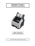
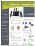
RATING PLATE
The rating plate is located on the rear panel of the washing machine.
If the casing needs to be replaced, remove the rating plate and attach it to the new casing.
The rating plate reports all the nominal data required by current standards (power supply voltage,
total absorbed power, etc...).
The serial number consists of 11 characters that indicate the date of manufacture and serial number:
For example:
{
{
2 0 0 6 03 0 0 0 0 1
{
4 figure number
denoting year of
manufacture (2006)
2 figure number denoting
the week of manufacture
(week five of 2006)
5 figures denoting the
progressive number
of the product during
the week of manufacture
Model. WA46E
2 0 0 6 0 3 0 0 0 0 1- 0 1 2 0 2 0 0 8 5 - 0 2
220 - 230
50Hz ...
220 - 230
{
Model. WA46E
2 0 0 6 0 3 0 0 0 0 1- 0 1 2 0 2 0 0 8 5 - 0 2
50Hz ...
Manufacturers product
identification code
Should any problems occur with the washer drier, the Main Technical Assistance Office in your country must be
informed of the serial number and the model in question in order to help the manufacturer identify the product.
S.M.P.E.02.A
18-07-06
S.M.P.E.03.A
18-07-06
P14
P16
IF
PRL
PRH
PREH
DSS
POT-TH
POT-VE
PROG
SONDA
TACHO
PS
EVL
EVP
EVB
EVH
EVC
Att-A
Att-B
HE
AS
TH
CU
M
TM
RF
BC
RF
Radio-Interference Suppressor
Low level pressostat
High level pressostat
Pressostat
Micro delay switch
Variable Temperature potenziometer
Variable spin speed potenziometer
Programmer
Thermal resistivity
Tachometer
Drain pump
Washing Water Valve
Pre-Washing Water Valve
Bleaching Water Valve
Hot Water valve
Cold Water valve
Washing actuator
Prewashing actuator
Washing Heating element
ON - OFF button
Fixed thermostat
Control unit
Main washing motor
Thermal cut-off
Heating Fuse Protector
Stoppage Drum Sensor
Abreviation English Descriptions
PREH
P11
Italian
HE
Filtro antidisturbo
Pressostato liv.basso
Pressostato liv.alto
Pressostato
Bloccoporta
Potenziometro temperatura
Potenziometro centrifuga
Programmatore
Termoresistenza
Tachimetrica
Pompa scarico
Elettrovalvola Lavaggio
Elettrovalvola Pre-Lavaggio
Elettrovalvola Candeggina
Elettrovalvola calda
Elettrovalvola fredda
Attuatore lavaggio
Attuatore prelavaggio
Resistenza lavaggio
Pulsante On - Off
Termostato fisso
Modulo elettronico
Motore lavaggio
Protettore Termico Motore
Fusibile resistenza
Sensore Blocco Cestello
FAN
R
(F4)
(F5)
(F6)
6
cnB
9
1 2 3 4 5 6 7 8 9
PCB 9v.
(F10)
1
RF
BP2-OUT
(F8)
(F9)
P14
BP1
(F7)
(F3)
1
4
IN - BP3
NEUTRO
P11
TAB 4v.
TAB 6v.
BP1
FASE
(F2
cnF
(F1)
EVB
Common
N
1
EVL
Common
EVB
EVP
Common
EVL
EVP
IF
1 2
1
cnM
CU
11
3 4 5 6 7 8 9 10 11
PCB 11v.
BROWN
GREY
WHITE
Mo t o r
BLACK
PS
FAL
TM
STAT2
1/2
campo
L
ROT 2
STAT 1
BP2
VIOLET
BLUE
TACHO
BP3
ROT 1
cnT
cnS 4
1 2 3 4
1
PINK
LIGHT BLUE
L
e
d
s
Flat cable
connection
Mother board
Front panel
RED
S
w
i
t
Front Panel c
h
e
s
PCB 4v.
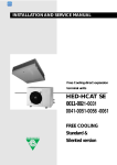
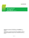
COMPONENTS SIDE
SAMPLE OF WIRING DIAGRAM
SONDA
DSS
Progr.
TECHNICAL DATA
Description of electrical components
1.
General
specifications
2.
Drum speed
3.
Tubular wash heater element with internal fuse
HE
Voltage (according to the model)
Max. absorption
Fuse
Slow spin
High speed spin
Power rating
Voltage (according to the model)
Power rating
Voltage
Flow rate
Height of drain hose
PS
5.
Safety door catch
BP2
1900 W
240 V
approx. 34
230-240V AC
20
max. 0,90
min. 0,60
W
50Hz
l/min.
m
m
At the end of the cycle, wait for the END indicator to light up before
opening the top lid.
BP1
6.A
1900 W
230 V
When a wash program is in progress, a safety device prevents the top lid
from being opened. To open it while a wash program is running, switch off
the washing machine using the On/Off button (if present) or position the
programmer knob on "Stop". The lid can then be opened after a time lapse
of approximately 2 minutes.
DSS
BP3
550 rpm
according to the model
Warning: the Blue terminal indicates the internal thermofuse (RF)
RF
Synchronous drain pump
4.
230V /240V ± 10% / 50 Hz
2200 W
10 A
Version with fixed safety thermostat with incorporated thermistor
NTC Fast sensor contacts in
(water in tub temperature sensor)
2
silvered metal
TR
Thermostat contacts
1 Fast- in non-silvered
metal
Open
Close
92°C ±3 50°C ±10
T90
6.B
Fixed safety thermostat 92°C ±3 with automatic reset and Normally Closed
Contact.
The NTC sensor allows precise control of the temperature (+/- 2°C). As the
temperature of the water increases, the ohmic resistance of the sensor
decreases.
To check the operation of the component, heat the water to 25°C, then use
a tester to check that the ohmic resistance is around 5 kOhm.
PROBE
Version with fixed safety thermostat and separate thermistor
(water in tub temperature sensor)
TR
The NTC sensor allows precise control of the temperature (+/- 2°C).
As the temperature of the water increases, the ohmic resistance of the
sensor decreases.
To check the operation of the component, heat the water to 25°C, then use
a tester to check that the ohmic resistance is around 5 kOhm.
PROBE
Open
90°C ±3
T90
7.
Pressure Switch
P11
P16
P14
PREH
Close
> 75°C
Fixed safety thermostat 92°C ±3 with automatic reset and
Normally Closed Contact.
A single level pressure switch is used with the following functions:
P11-P14
- Signals the electronic control unit (open/closed) that the low
water level has been reached.
- heater element safety switch.
Contact P16 functions as an overflow safety device and trips when there is
too much water in the tub.
Washing machine fill levels.
The washing machine levels are calculated by the electronic control unit
according to the type and quantity of washing placed in the tub and the set
program, and adds a safety margin which is pre-programmed in the module
software.
S.M.P.E.04.A
18-07-06
Description of electrical components
TECNICAL DATA
Version with 3-way cold water solenoid valve.
8.
1
2
EVP
Prewash
EVL
Wash
EVB
Bleach
3) Prewash
3
2) Wash
1) Bleach
White coil Flow rate:
Working pressure:
Black coil Flow rate:
Working pressure:
MAX.
MIN.
MAX.
MIN.
10 ±15%
0,05 - 1
10 ±15%
0,05 - 1
l / min
MPa
l / min
MPa
Grey coil Flow rate:
Working pressure:
MAX.
MIN.
7 ±25%
0,05 - 1
l / min
MPa
Voltage (according to the model)
9.
230/240V 50-60Hz
Wash program selection potentiometer.
The electronic washing machines can be fitted with one of two types of positive logarithmic potentiometer:
- 50 kOhm with 16 fixed positions
- 63 kOhm with 20 fixed positions
Their use depends purely on the number of programs for which the appliance has been designed.
The maximum Ohmic resistance is the reference value used to start the Autotest procedure.
6
Progr.
Wiring diagram symbols
7
8
STOP
9
8
10
5
11
12
4
13
3
2
1
16
15
9
10
STOP
11
12
13
1
7
Important:
The positions in red are
those used for the
various phases of the
autotest.
14
6
15
5
4
16
3
2
1
14
50 kOhm with 16 fixed positions
1
20 19
18
17
1
63 kOhm with 20 fixed positions
Program selector.
The start of a particular program is commanded by a wash code sent by the program selector (potentiometer) to the control
unit.
The process also depends on the pressure switch signal: An OPEN P11 - P14 contact enables the water feed or spin,
while a CLOSED P11 - P14 contact enables the motor to run during the wash and the heating phase.
The thermistor, tachometric and optional button signals are important for enabling the control unit microprocessor to run
the required program. Note that each wash code of the program selector corresponds to a number of operations managed
by the microprocessor.
Commutator motor 220-240V 50-60 Hz.
10.
The commutator motor can be powered by: direct current (DC), recognisable by the 1/2 FIELD contact on the
terminal board, or by alternating current (AC).
Appliances with 42 litre drum volume:
AC commutator motor
terminal board
- AC motor, spin speed 800 rpm -1100 rpm
- DC motor, spin speed 1200 rpm or higher.
DC commutator motor
terminal board
1/2 FIELD
For DC motors only
M1
Tachometric
Tachometric
Stator 1
Motor Thermal
Motor Thermal
Rotor 1
Rotor 2
Stator 2
M3
M4
M5
M6
M7
M8
M9
M10
Tachometric
Tachometric
Stator 1
Motor Thermal
Motor Thermal
Rotor 1
Rotor 2
Stator 2
IMPORTANT:
- It is not possible to replace just the tachometric on commutator motors.
- The motor brushes are not supplied as single spare parts.
- It is not technically possible to measure the ohmic resistance of this type of motor using a tester.
- The nominal data is reported on the motor itself.
S.M.P.E.05.A
18-07-06
TECHNICAL DATA
Water fill principle
At the start of the wash program, the control unit, according to the program selected, commands the solenoid valve to
feed water to the appliance providing the pressure switch authorises the action (the pressure switch must be OFF i.e.
with contact P11-P14 open). When the required water level has been reached, the control unit closes the solenoid valve.
(pressure switch with contact P11-P14 closed).
SAFETY:
If the pressure switch detects excess water entering
the appliance, it sends a signal to the control unit
which then starts the drain pump.
Pressure switch
Program
Selector
Solenoid valve
Electronic control unit
Heating phase principle
The heater element switches on when pressure switch contact P11-P14 is closed (water in the tub). A traditional
thermostat to interrupt the power supply to the heater element is not provided.
The control unit receives the Ohmic value of the resistance and switches off the heater element when the correct
temperature has been reached.
Program
Selector
Thermistor
Pressure switch
L
N
Modulo
elettronico
IF
Fuse
Heater element
Cooling
The cooling phase is necessary in order to ensure that the water pumped to the domestic drainage system is not
too hot.
This is always carried out for the COTTON program if the temperature is higher than 70°C. The water is gradually
cooled down by allowing cold water to enter after the last wash cycle and before draining. The control unit feeds the
cold water for one minute, pauses one minute then drains.
During DELICATE and SYNTHETIC programs, the cooling is always carried out before draining by activating the
solenoid valve for 10 seconds.
Wash load balance control
The washing machines are fitted with an electronic balance control which is active in all the spinning phases.
At the start of the spin cycle, the load balance is checked by the control unit. If the load in the drum is unbalanced, the
washing machine attempts to start the spin a number of times. If the control unit detects that the load is very unbalanced,
the entire spin cycle may last as long as 20 minutes (even if the display still shows 12' (minutes).
S.M.P.E.06.A
18-07-06
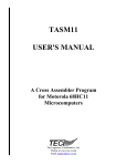
Electronic control unit contacts
TECHNICAL DATA
1
2
Electronic washing machine version
with water feed through 3-way
solenoid valve.
3
1
2
cnF
1
3
4
5
TAB 4v.
4
6
7
cnT
1
8
9
10
6
(F4)
(F2
(F1)
IN - BP3
NEUTRO
P11
FASE
(F3)
P14
R
BP1
(F5)
(F8)
(F7)
RF
BP2-OUT
PCB 9v.
2 3 4 5
(F9)
(F10)
1
1
6
EVL
9
7 8 9
cnB
cnM
11
7 8 9 10 11
TR
1
cnS 4
1 2 3 4
Progr.
Control Unit
5 6
M4 M3
TACHO
SONDA
PCB 11v.
STAT2
1 2 3 4
1
ROT 2
M10
TM
M9
ROT 1
1/2
campo
M6 M7
PCB 4v.
COMPONENTS SIDE
Motor (Rotor 1)
Motor (Tachometric)
Motor (Tachometric)
Thermistor (temperature control sensor)
STAT 1
M1
cN1
cN2
cN3
cN4-5
EVP
PS
M8
Motor (Thermal)
Motor (1/2 field)
Motor (Stator 2)
Motor (Thermal)
Motor (Stator 1)
Motor (Rotor 2)
EVB
EVL
Common
M5
cM1
cM2
cM3
cM4
cM5
cM6
EVP
Common
Universal Motor
cnB1 -----------cnB2 feeds Fabric Conditioner Solenoid Valve EVB
cnB3 -----------cnB4 common to Solenoid valves EVP, EVL, EVB.
cnB5 power supply Prewash solenoid valve EVP (Prewash)
cnB6 power supply Prewash solenoid valve EVL (Wash)
cnB7-8 power supply Drain pump
cnB9 return signal from pressure switch overfill safety (P16),
starts drain pump.
EVB
Common
TAB 6v.
(F6)
FUNCTIONS OF THE CONTACTS
cnF1 receives power from the mains supply (Phase)
cnF2 feeds door catch contact BP3
cnF3 current output to mains supply (Neutral)
cnF4 feeds pressure switch contact P11
cnT1 feeds the heater element
cnT2 --------------cnT3 receives the pressure switch level reached signal
from contact P14
cnT4 feeds door catch contact BP1
cnT5 receives the return signal from the heater element through
safety thermostat
cnT6 feeds door catch contact BP2
Flat cable
connection
ALLA
SCHEDA DISPLAY
( TO DISPLAY )
cnS1-2 Program selector potentiometer
Flat cable receives information from the pushbutton circuit board (wash options) and sends information to the display
(program status).
The use of different types of wiring means that the number of connectors may vary, though the control unit is always the
same. Consequently, the wiring diagram shown above remains valid (providing the connectors have been wired correctly)
in that it refers to the contacts on the control unit itself.
In the case of a fault, always check the control unit contacts (connectors). A false contact can compromise the correct
execution of the program.
Explanation of the data reported on the electronic control unit label:
A = Maximum spin speed
B = Information for line testing
C = Voltage/Frequency
D = Control unit type
E = Appliance type
F = Control unit production date
G = Control unit code
H = Control unit/update version
I = Control unit barcode
A
xxxx
85SX-85DX
220-240 V / 50Hz
B
C
D
E
G
Example:
MINISEL
LAE42 14/06/2004
F
H
546063200 -01
I
IMPORTANT:
Before replacing an electronic control unit, use the autotest to make sure that all the electric components
are working properly, that the contacts of the electronic control unit connections are sound and that
the mains voltage is within the required limits.
S.M.P.E.07.A
18-07-06
Positions of the buttons on the various model styles:
General:
There are different types of electronic washing machines: with or without LCD Display. These types may be
further subdivided according to their particular styling in terms of the positions of the wash option buttons.
This, however, does not influence the operation of the appliance, in that the operation of the electronic control
unit is the same in all cases, regardless of any extra functions that may be available on some models.
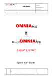
Example of an appliance with 1 knob and without display- Model style CM - 4 buttons
1
Prewash Selector
2
2
Energetic wash selector
Manual Autotest Selector
3
No-spin selector
4
Program start selector
Stop
90°
60°
40°
35°
30°
30°
60°
40°
1
3
2
4
40°
40°
30°
Example of an appliance with 1 knob and without display- Model style CM - 7 buttons - 12 leds
1
2
3
Delayed start selector
Spin speed selector
Prewash selector
4
4
Energetic wash selector
Manual Autotest Selector
5
Extra rinse selector
6
Depending on the model
6.1
Anti-crease selector
6.2
Spin delay selector
6.3
Drying selector
6.4
Stain removal selector.
7
Stop
90°
60°
40°
35°
30°
30°
1
2 3
4
5
6
60°
40°
7
40°
40°
30°
Program start selector
Example of an appliance with 1 knob and with large display- Model style CM - 7 buttons - LCD
1
2
3
Delayed start selector
Spin speed selector
Prewash selector
4
4
Energetic wash selector
Manual Autotest Selector
5
Extra rinse selector
6
Depending on the model
6.1
Anti-crease selector
6.2
Spin delay selector
6.3
Stain removal selector.
7
Stop
90°
60°
40°
35°
30°
30°
60°
40°
1 2
3
4
5
6
7
40°
40°
30°
Program start selector
S.M.P.E.08.A
18-07-06
Pushbutton specifications
Description of the functions of the selector buttons:
Delayed start button
This button allows a delayed start to be programmed for a selected wash program.
The set delay time is displayed by the timer LCD in hours:minutes (delays possible from 1 to 16
hours) or by the leds above the button (for models without display). The setting is confirmed by
pressing the Start button, the Delay button will then light up to indicate that the function has been
activated.
With the timer display at zero, the Delay button indicator light will switch off and the Start button
will light up.
During the delay phase, the Delay button remains enabled to allow the delay setting to be modified.
Spin speed setting button (this button is not illuminated)
The button allows the maximum spin speed to be modified and/or reduced to zero. The set spin
speed is displayed by the LCD or by the leds above the button (for models without display).
The initial speed setting displayed is the maximum allowed for the set program. The spin speed
can also be modified during the wash cycle.
NB: Excluding the spin also excludes the DRYING function (in the case of Washer/driers).
No-spin button
This button allows the spin function to be included or excluded from the wash cycle.
The button is not normally lit but lights up when the function has been selected.
Prewash button
This button includes or excludes the prewash (see specifications) from the wash programs that
accept the function (see program table in the instruction book).
The button is not normally lit but lights up when the function has been selected.
Energetic wash button
This button includes or excludes the energetic wash (see specifications) from the wash programs
that accept the function (see program table in the instruction book).
The button is not normally lit but lights up when the function has been selected.
Extra rinse or extra rinses button (depending on the model)
This button includes or excludes the extra rinses (see specifications) from the wash programs that
accept the function (see program table in the instruction book). The button is not normally lit but
lights up when the function has been selected.
Anti-crease button
This button includes or excludes the anti-crease function from the wash programs that accept
the function (see table in the instruction book).
The button is not normally lit but lights up when the function has been selected.
The anti-crease function limits the maximum spin speed to 800 or 1000 rpm (depending on the
model), after which the drum rotates clockwise and anticlockwise at 35 rpm for 30 minutes with
cycles of 7 seconds ON and 2 minutes OFF.
Spin delay
This button includes or excludes the spin delay function from the wash programs that accept the
function (see table on the instruction book).
The button is not normally lit but lights up when the function has been selected.
The spin delay function stops the wash cycle at the last rinse and the button indicator light flashes.
The appliance will remain in this condition until the flashing button is pressed, after which the light
will switch off and the cycle will restart to complete the program.
S.M.P.E.09.A
18-07-06
Pushbutton specifications
Stain removal button (if fitted to the appliance)
This button allows the stain removal function to be included or excluded from the 60°C COTTON
program.
The button is not normally lit but lights up when the function has been selected.
NB: When the stain removal function is activated, the prewash button is disabled
Stain removal program description
Place the usual detergent in the wash compartment and the special stain removal detergent in the
prewash compartment.
After the first 10 minutes, the water is heated up to 40°C and the detergent is taken from the main
wash compartment.
Once 40°C has been reached, water is fed through the prewash compartment for approximately
10 seconds (taking with it the stain removal detergent). The water is then further heated up to 60°C
and remains at this temperature for approximately 10 minutes. The wash then continues for a
further 40 minutes and then on to the rinses, etc. etc.
Start button
This button confirms the previously set functions and starts the program.
The button is not normally lit, but lights up to indicate the cycle is running only if the door catch
is closed. In the version with the LCD, when the program selector is positioned on "Stop", the
cycle is stopped and the button light switches off.
In the version without a display, when the program selector is positioned on "Stop", the cycle is
stopped and the button light flashes.
DISPLAY version mod. B
The wash symbols indicate the current phase of the program running:
= Wash phase
= Rinse phase
= Spin phase
Timer display:
- wash time in hours:minutes
- delay time in hours:minutes (settable from 1 to 16 hours in steps of 1 hour)
- end of program indicated by the word End
Spin speed and No-spin function:
- The spin symbol is always lit.
- The spin speed can be set from the maximum allowed for the selected
program down to 500 rpm in steps of 100.
- The next press selects the No-spin function and is displayed by "00".
NB: When the program is reset, the display switches off.
S.M.P.E.10.A
18-07-06
CONTROL PANEL
Program and Temperature selector knob
STOP
Stop
This knob is used to select the type of wash and the most appropriate temperature for
the items to be washed.
Positioning the knob at the "STOP" position will reset the programming of the appliance.
If, for any reason, you want to change the set wash program or add more washing to
the load during the wash cycle, simply place the programmer knob on STOP ( the
DISPLAY and the START button will switch off) then re-position the knob on the
new program and press the START button.
N.B.
After carrying out this operation, check that there is detergent in the appropriate compartment and add if
necessary.
Warning:
Only use this function if strictly necessary and then only if the program to reset has been running for
less than 3 minutes. Before opening the top lid after a reset, wait 2 minutes for the locking mechanism
to release.
IMPORTANT:
The time reported on the display is purely indicative even though it is updated continuously during the wash cycle.
The wash time, in fact, can be influenced by a number of factors:
- Temperature and Pressure of the mains water supply system
- Voltage
- Quantity of washing and types of fabric in the drum.
These electronic appliances are fitted with an EASY LOGIC system that automatically recognises the quantity of
washing placed in the drum. This function regulates the duration of the wash and quantity of water used, thus saving
water, time and energy.
In the case where the amount of washing is less than the maximum recommended load (see washing machine
instruction book), the quantity of water used for the wash will be reduced in proportion to the wash load.
In the case of a half-load or less, the machine will automatically carry out one rinse less than that programmed.
N.B. The EASY LOGIC function is only active for cotton programs.
General:
Always start by checking the other components involved, and then check the electronic control unit last.
The following examples are provided assuming that all connections and connectors are in good working order, and that
the voltage is within the required limits.
The electronic Control Unit has a self-diagnostics function that checks all the components connected to it, i.e. the socalled Autotest.
S.M.P.E.11.A
18-07-06
MANUAL AUTOTEST
To carry out the test, the following start conditions must be satisfied:
- The washing machine must be cold and empty. This is very important
in that this phase tests both the thermistor and the pressure switch
in OFF condition.
12
3
9
Procedure:
- Set the wash program selector knob with the index mark
at 6-o-clock (Maximum Ohmic resistance value).
6
For appliances with 7 pushbuttons and
LCD Display:
To start the appliance in autotest mode,
press button 4.
Stop
90°
60°
40°
35°
30°
30°
60°
40°
1 2
3
4
5
6
7
40°
Manual Autotest Selector
30°
6-o-clock
For appliances with 7 pushbuttons and
no Display:
To start the appliance in autotest mode,
press button 4.
Stop
90°
60°
40°
35°
30°
30°
1
2 3
4
5
6
60°
40°
7
40°
Manual Autotest Selector
For appliances with 4 pushbuttons and
no Display:
To start the appliance in autotest mode,
press button 2.
40°
40°
30°
6-o-clock
Stop
90°
60°
40°
35°
30°
30°
60°
40°
1
2
3
4
40°
Manual Autotest Selector
40°
30°
6-o-clock
S.M.P.E.12.A
18-07-06
AUTOTEST for appliances with LCD display
The combination Knob (6-o-clock) and Autotest Selector button pressed for 5-6 seconds
starts the Autotest.
The display will light up fully
for a few seconds together
with some of the buttons.
Stop
90°
60°
40°
35°
NB:
The colour used for the
display, the buttons and
the knob has no significance.
30°
30°
60°
40°
1 2
3
4
5
6
7
Manual Autotest Selector
40°
40°
30°
6-o-clock
This test will automatically check the following:
- That the Thermistor is not in short-circuit or disconnected.
- the Pressure Switch OFF condition (no water in tub)
- that the Door catch is working properly (contact closed)
- that the Program selector is connected properly
If the result of the test is positive, all the symbols on the display will light up.
Button illumination test:
- The Spin speed selection button is not luminous.
- The Delayed start button only lights up when pressed.
- The Start button only lights up when pressed.
- All the other buttons change their status from On to Off, or vice versa, each time they are
pressed.
The spin speed selection button can change the set rpm at any time if pressed
during the test.
N.B.: This button is not luminous.
On some models, the No Spin function is disabled
during the Autotest phase.
The Start button switches the display wash/dry symbols on and off cyclically.
The programmer knob selects the various phases of the test, which are then displayed by
the timer as described in "Manual Test Selection".
INTRODUCTION:
The electronic control unit also allows individual components to be tested by varying the knob setting and maintaining the
other conditions unchanged. Once the autotest function has been started, the required test can be selected by placing the
knob in the appropriate position. Each position of the knob corresponds to a component test.
Starting from the start position (6-o-clock) and rotating the knob anticlockwise one position at a time there are 5 tests
that can be carried out. Except for the first test, which is carried out by the control unit itself, in order to verify the result
of the test, the behaviour of each tested component must be monitored.
The control unit takes a few seconds to pass from one test to the next. The acceptance of the test is signaled by the leds
switching off or by a display code indicating the program corresponding to the position of the knob in autotest. From this
point on, all the suspect components can be tested.
The correspondence between the reference position of the knob and a wash program is purely indicative, in that this is
linked to the appliance model in question.
S.M.P.E.13.A
18-07-06
DIAGNOSTICS TABLE
Summary table of the tests that can be carried out on
appliances with an LCD Display and fitted with
a 3-way Solenoid valve.
Test N° 1
Possible displays according
to the appliance model
under test.
- Start position, all the functions are deactivated.
h.m.
Position of
knob index
mark
h.m.
The control unit automatically tests the operation of the
thermistor, the pressure switch OFF condition (no water in
tub), the program selector and the door catch closed condition.
1
6-o-clock
position
Test N° 2
- Fills with water through the cold solenoid valve until the first
pressure switch level is reached.
h.m.
h.m.
This procedure tests the operation of the solenoid valves
and pressure switch.
2
Test N° 3
- The heater element is activated (only with water)
- The motor rotates alternately in both directions
(clockwise and anticlockwise).
h.m.
h.m.
This procedure tests the operation of the heater element,
the motor during washing.
Test N° 4
N.B.: In Autotest, on some models the No Spin function is disabled.
3
h.m.
h.m.
- The drain pump is activated and the spin runs at the preset speed.
This procedure tests the operation of the drain pump,
the motor in spin mode.
Test N° 5
- Fills with water for 10 seconds through the hot solenoid valve, where fitted
(only with pressure switch off), wash motor operation at different rpm and
direction according to the model of electronic circuit board fitted to the
appliance. During this phase, for appliances fitted with a drum positioning
sensor, the start led flashes if operation is correct otherwise it will remain
lit.
4
h.m.
This procedure tests the operation of the hot water solenoid valve
(where fitted and only with pressure switch OFF) , the motor during
washing and the drum positioning.
5
S.M.P.E.14.A
18-07-06
AUTOTEST for electronic appliances with 7 pushbuttons and no display
The combination Knob (6-o-clock) and Autotest Selector button pressed for 5-6 seconds
starts the Autotest.
When the washing machine is
powered up, the test begins.
The power led and the pushbuttons
light up.
Stop
90°
60°
40°
35°
30°
30°
NB:
The colour used for the buttons and
the knob has no significance.
1
2 3
4
5
6
7
60°
40°
40°
Manual Autotest Selector
40°
30°
6-o-clock
This test will automatically check the following:
- That the Thermistor is not in short-circuit or disconnected.
- the Pressure Switch OFF condition (no water in tub)
- that the Door catch is working properly (contact closed)
- that the Program selector/Spin speed selector is connected properly
If the result of the test is positive, the 4 (washing phases) leds are in "Test 1" condition (see next page), the
pushbuttons switch off and all the functions of the washing machine can be tested through the programmer knob.
Button illumination test:
- The Spin speed selection button is not luminous.
- The Delayed start button only lights up when pressed.
- The Start button only lights up when pressed.
- All the other buttons change their status from On to Off, or vice versa, each time they are
pressed.
N.B.: On some models, the Delayed start button is not luminous.
The spin speed selection button can change the set rpm at any time if pressed
during the test.
N.B.: This button is not luminous.
On some models, the No Spin function is disabled during the Autotest phase.
The Start button switches the display washing symbols on and off cyclically.
The programmer knob selects the various phases of the test, which are then displayed by
the timer as described in "Manual Test Selection".
INTRODUCTION:
The electronic control unit also allows individual components to be tested by varying the knob setting and maintaining the
other conditions unchanged.
Once the autotest function has been started, the required test can be selected by placing the knob in the appropriate
position. Each position of the knob corresponds to a component test.
Starting from the start position (6-o-clock) and rotating the knob anticlockwise one position at a time there are 5 tests that
can be carried out. Except for the first test, which is carried out by the control unit itself, in order to verify the result of the
test, the behaviour of each tested component must be monitored.
The control unit takes a few seconds to pass from one test to the next. the acceptance of the test is signaled by the
switching off of the leds indicating the program corresponding to the position of the knob in autotest. From this
point on, all the suspect components can be tested.
The correspondence between the reference position of the knob and a wash program is purely indicative, in that this is
linked to the appliance model in question.
S.M.P.E.15.A
18-07-06
MANUAL AUTOTEST - For model styling with 7 pushbutton control panel and no display
}
WASH
PHASE LEDS
Stop
90°
60°
40°
35°
30°
30°
1
2 3
4
5
6
40°
7
Manual Autotest Selector
60°
40°
40°
30°
6-o-clock
Setting the programmer knob at the positions described below will
test the electric components and functions of the washing machine.
Position of
knob index
mark at
6-o-clock
Status of
the wash
phase
leds
Test N° 1
- Start position, all the functions are deactivated.
The control unit automatically tests the operation of the
thermistor, the pressure switch OFF condition (no water in
tub), the program selector and the door catch closed condition.
1
Test N° 2
- Fills with water through the cold solenoid valve until the first
pressure switch level is reached.
This procedure tests the operation of the solenoid valves
and pressure switch.
2
Test N° 3
- The heater element is activated (only with water)
- The motor rotates alternately in both directions
(clockwise and anticlockwise).
This procedure tests the operation of the heater element,
the motor during washing.
Test N° 4
3
N.B.: In Autotest, on some models the No Spin function is disabled.
- The drain pump is activated and the spin runs at the preset speed.
This procedure tests the operation of the drain pump,
the motor in spin mode.
Test N° 5
4
- Fills with water for 10 seconds through the hot solenoid valve, where fitted
(only with pressure switch off), wash motor operation at different rpm and
direction according to the model of electronic circuit board fitted to the
appliance. During this phase, for appliances fitted with a drum positioning
sensor, the start led flashes if operation is correct otherwise it will remain
lit.
This procedure tests the operation of the hot water solenoid valve
(where fitted and only with pressure switch OFF) , the motor during
washing and the drum positioning.
5
S.M.P.E.16.A
18-07-06
AUTOTEST for low speed electronic appliances with 4 pushbuttons
The combination Knob (6-o-clock) and Autotest Selector button pressed for 5-6 seconds
starts the Autotest.
When the washing machine is
powered up, the test begins.
The power led and the pushbuttons
light up.
Stop
90°
60°
40°
NB:
The colour used for the buttons and
the knob has no significance.
35°
30°
30°
60°
40°
1
2
3
4
Manual Autotest Selector
40°
40°
30°
6-o-clock
This test will automatically check the following:
- That the Thermistor is not in short-circuit or disconnected.
- the Pressure Switch OFF condition (no water in tub)
- that the Door catch is working properly (contact closed)
- that the Program selector is connected properly
If the result of the test is positive, the power led lights up, the pushbuttons switch off and all the functions
on the appliance can be tested through the programmer knob.
Button illumination test:
- The Spin speed selection button is not luminous.
- All the other buttons change their status from On to Off, or vice versa, each time they are
pressed.
The programmer knob selects the various phases of the test, which are then displayed by
the timer as described in "Manual Test Selection".
INTRODUCTION:
The electronic control unit also allows individual components to be tested by varying the knob setting and maintaining the
other conditions unchanged. Once the autotest function has been started, the required test can be selected by placing the
knob in the appropriate position. Each position of the knob corresponds to a component test.
Starting from the start position (6-o-clock) and rotating the knob anticlockwise one position at a time there are 5 tests
that can be carried out. Except for the first test, which is carried out by the control unit itself, in order to verify the result
of the test, the behaviour of each tested component must be monitored.
The control unit takes a few seconds to pass from one test to the next. The acceptance of the test is signaled by the
power led which changes its status from "flashing" to "ON". From this point on, all the suspect components can be tested.
The correspondence between the reference position of the knob and a wash program is purely indicative, in that this is
linked to the appliance model in question.
S.M.P.E.17.A
18-07-06
MANUAL AUTOTEST - For model styling with 1 knob and 4 pushbuttons
LUMINOUS POWER
BUTTONS
LED
Stop
90°
Setting the programmer knob at the
positions described below will test the
electric components and functions of
the washing machine.
}
60°
1
2
3
4
Manual Autotest Selector
N.B.: Passing from one test to another takes a few seconds;
during this time the Power LED flashes.
40°
35°
30°
30°
60°
40°
40°
40°
30°
6-o-clock
Power
led
Knob Index
Position
6-o-clock
Test N° 1
- Start position, all the functions are deactivated.
The control unit automatically tests the operation of the
thermistor, the pressure switch OFF condition (no water in
tub), the program selector and the door catch closed condition.
1
Test N° 2
- Fills with water through the cold solenoid valve until the first
pressure switch level is reached.
This procedure tests the operation of the solenoid valves
and pressure switch.
Test N° 3
2
- The heater element is activated (only with water)
- The motor rotates alternately in both directions
(clockwise and anticlockwise).
This procedure tests the operation of the heater element,
the motor during washing.
Test N° 4
3
N.B.: In Autotest, on some models the No Spin function is disabled.
- The drain pump is activated and the spin runs at the preset speed.
4
This procedure tests the operation of the drain pump,
the motor in spin mode.
Test N° 5
- Fills with water for 10 seconds through the hot solenoid valve, where fitted
(only with pressure switch off), wash motor operation at different rpm and
direction according to the model of electronic circuit board fitted to the
appliance.
5
This procedure tests the operation of the hot water solenoid
valve (where fitted and only with pressure switch OFF) and the
motor during washing.
S.M.P.E.18.A
18-07-06
TROUBLESHOOTING GUIDE
Before carrying out any operations on a component check the quality of the electrical
connections to the electronic control unit.
Check the condition of the wiring harness (for wear, twists, breakages) and the
connections.
Always start by checking the other components involved, and then check the electronic
control unit last.
V
W
HT 3502
V
HOLD
OFF
max 10A
fused
max
600v
COM
µA
10A
RANGE
mA
VWmA
AUTO OFF
CAT II
max 600v
400mA fused
AUTO AC-DC SELECTION
10A
The program will not start.
Try the Manual Autotest
A) If the appliance DOES NOT enter autotest mode, recognisable by the following components not lighting up:
- Leds (for appliances with a small display and 1 knob or 2 knobs without display.
- Large LCD display for appliances fitted with same.
Then the following checks must be carried out:
- Check that the electrical connections of the Potentiometer are correct and according to the wiring diagram, that the component
is undamaged and in working order, otherwise replace the component.
- Check that the electrical connections of the pushbutton circuit board are inserted correctly. If so, and the problem persists,
replace the pushbutton circuit board. Finally, if this doesnt solve the problem, replace the main electronic control unit.
B) If the appliance ENTERS autotest mode, depending on the type of appliance, the following components will light up:
1) For appliances with no display, the wash phase leds will all remain lit.
2) For appliances with an LCD display, the display illumination will be minus graphics.
If this occurs, it means that the control unit has discovered a malfunction in one of the three components that it is testing:
- the thermistor.
- the pressure switch
- the door catch
To check the operation of the thermistor:
- Disconnect the wiring from the thermistor and use a multimeter (Tester) to check the ohmic resistance, which should
be approximately 5 kOhm at an ambient temperature of 25°C,
- if the result is positive, check the Pressure switch.
- if the result is negative, replace the Thermistor.
To check the operation of the Pressure switch:
- Disconnect the electrical wiring from the Pressure switch and check that contact P11-P14 is open,
- if the result is positive, check the Door catch.
- If the result is negative, check that the pressure switch pipe and the compression chamber are not blocked.
if these are OK, replace the Pressure switch.
To check the operation of the Door catch:
- Check that connections BP1, BP2 and BP3 have been properly made.
- Use a Tester to check the voltage between contact BP3 and BP1.
- if the test result is positive, replace the component
- If there is no voltage, replace the electronic control unit.
Once this procedure has been completed, the problem should have been resolved and the appliance should work properly.
S.M.P.E.19.A
18-07-06
DIAGNOSTICS TABLE
Water does not enter the tub.
Check that the water feed valve to the washing machine is open.
Start the manual Autotest procedure, then carry out Test N° 2. If water still does not enter the tub, use a Tester to carry
out the following checks:
- check that there is Ohmic resistance (Ohms) between the two terminals of the solenoid valve, if the circuit is open
replace the component.
- check that there is voltage at the ends of the wires connecting the solenoid valve to the control unit. If there is no
voltage, replace the electronic control unit.
The washing machine does not heat the water in the tub.
Start the manual Autotest procedure, then carry out Test N° 2 to fill the tub with water (this is necessary in order to allow the
heater element to work). On completion of this operation, carry out Test N° 3. If the water is still not heated, use a Tester to
carry out the following checks:
- check that there is Ohmic resistance (Ohms). If the circuit is open, replace the component.
- check that there is continuity between the two contacts of the T90° safety thermostat (if fitted), if the circuit is open replace
the component.
- check that there is voltage at the ends of the wires connecting the heater element to the control unit. If there is no voltage,
replace the electronic control unit.
The motor does not turn properly during a wash and/or spin
Start the manual Autotest procedure and then carry out Test N° 3.
- Check that he motor rotates alternately in both directions (clockwise and anticlockwise) at approximately 45 rpm.
If the result is positive, carry out Test N° 4.
If the test is negative, disconnect the motor from the wiring terminal board, then use a Tester to check that there is continuity
at the ends of the wires connecting the wiring terminal board to the control unit. Then check that the connectors are not
damaged or disconnected.
- Replace the motor with one known to be in working order. If the result of the test is positive, replace the motor. If the result
is negative, replace the electronic control unit and refit the original motor.
The appliance does not drain
Check that the washing machine filter or the users drains are not blocked.
Start the appliance in manual Autotest mode and move the programmer knob to the Test N° 2 position. Wait for the pressure
switch to trip and then carry out Test N° 4.
If the result is negative, disconnect the pump wiring and check that the circuit is no broken by verifying the ohmic resistance
(Ohms). If the circuit is open, replace the electric pump.
- if the circuit is closed, remove the pump from the washing machine and use a screwdriver to check for any foreign bodies
in the scroll.
- use a tester to check the continuity in the pump power supply wires. If all the tests carried out prove positive replace the
control unit.
S.M.P.E.20.A
18-07-06
DIAGNOSTICS TABLE
Water flows into the tub continuously.
- Check that the solenoid valve is not damaged (water should not enter the tub when the appliance is switched off).
- Check that the pressure switch is working by carrying out Test N° 2.
- Check that Pressure switch contact P11- P14 is closed, allow this phase of the test to continue for a few minutes,
then make sure that there are no air leaks.
- Check that there are no leaks from the gaskets, rubber couplings or tub unit.
- Check that the pressure switch pipe is not holed or bent.
- If all the above tests are positive, replace the electronic control unit.
SAFETY measures adopted in the electronic control unit software.
- Motor rotor jammed or Tachometric open.
After eight failed attempts to start the motor (either in wash or spin mode), the control unit passes to
the end of the cycle and the End led flashes on appliances without a display or the word End appears
on appliances with a display.
- Drain Pump blocked.
If the control unit does not detect the pressure switch empty condition after twenty minutes of pump
running time, it passes to the next step and continues the cycle until the end of the program, stopping
with water still in the tub.
- Thermistor or thermostat malfunction
If, after fifty minutes of heater element operation the set temperature has not been reached, the control
unit advances and continues the cycle as normal, though with cold water.
S.M.P.E.21.A
18-07-06