1
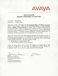
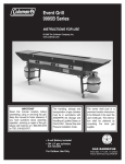
January 2, 2014
ATTENTION:
ELECTRICAL CONTRACTORS, SUPPLIERS AND
DISTRICT ENGINEERING, CONSTRUCTION & OPERATIONS
PERSONNEL
SUBJECT:
Electrical Service Manual (ESR)
Several revisions have been made to the ESR since the last publication. Please find enclosed the revised
documentation to be inserted in your manual. Current revisions are shown in red with a black vertical bar on
the left border. A brief description of the revisions are as follows:
Section 2. General Requirements
Pages 2-17 and 2-18 Variance Request form revised
Section 4. Underground Service
Pages 4-41 and 4-42 revised.
Page 4.41 provides more detailed requirements for a Vault Room.
Page 4-42 specifies 20’ of excess conductor required to comply with Figure 4-21.
Section 5. Meters and Service Entrance Equipment
Page 5-15 provides more detail for required door hardware required for Meter Rooms.
Section 6. Generation Interconnection
Pages 6-16 revised to provide more detailed informaion regarding the visible-open lockable
disconnect switch requirement.
All requirements are effective immediately. In order for you to have the most current information available
for reference please update your assigned ESR manual with the enclosed pages without delay.
NO. 45
Section 2. General Requirements
V.
FORM 2-1 — VARIANCE ROUTING
PUBLIC UTILITY DISTRICT NO. 1 OF SNOHOMISH COUNTY
INTERNAL VARIANCE APPLICATION ROUTING
(Signatures, Approval / Denial to be noted on Actual Variance Form)
Route To:
Mailstop:
1.
Designer / Engineer / Engineering Services
2.
Everett / Regional / Distribution Engineer Svcs. Mgr:
3.
OC / HL
Construction Superintendent:
4.
OM
Meter Dept. Superintendent:
5.
EB
Meter Reading Manager:
6.
02
Standards:
Routing:
x
Everett / Regional / Engineering Services; Route to appropriate Mgr.
and to Construction Superintendent-OPS for review.
x
South County Engineering route to Distribution Services Manager
and to Construction Superintendent-HL for review.
x
Other Regional Engineering offices, route to appropriate Distribution
Services Manager.
x
Additionally, all variances will be reviewed and approved / denied by
the District’s Standards Department.
x
Departments unaffected by the variance may be omitted from this
routing list.
x
Standards will be the final reviewer of the Variance Request and
send a copy of the approved or denied Variance to the appropriate
engineer or manager to notify the requestor. Standards will file the
original variance request and send a copy to the originator.
Rev. 12/24/2013
ELECTRICAL SERVICE REQUIREMENTS
New: 10/90
Revised: 06/15/2013
Page 2 - 17
Section 2. General Requirements
W.
FORM 2-2 — VARIANCE APPLICATION
PUBLIC UTILITY DISTRICT NO. 1 OF SNOHOMISH COUNTY
VARIANCE APPLICATION FOR DEVIATION
FROM STANDARD SERVICE REQUIREMENTS
Date:
/
/
Service Address:
Customer:
Address:
Phone: (
Eng./Architect:
Contractor:
Electrician:
Phone: (
Phone: (
Phone: (
)
Type of Service:
O.H.
Prints Available:
)
U.G.
Yes
Other Approvals Required:
Voltage
No
City
)
)
Load
Estimated Date of Service
County
/
/
Labor & Industries
Requested Date Variance Application Reply Is Needed:
/
/
(Adequate time for internal processing (10 day minimum) must be allowed)
Variance Requested: (include specific ESR reference(s) that cannot be complied with and reason for request).
Reason for Request:
Sketch: (attach other documents as necessary)
Complete all Variance information in full and submit with a copy of the appropriate New Service Questionnaire.
Variances must be approved by all Managers and departments affected by requested Variance, including
deviation from Electrical Codes, Standards and Electrical Service Requirements or Variance will be denied.
Variance Request Reviewed and Approved by:
Customer/Distribution Designer/Engr: _______ Date:___/___/___
Regional/Distribution Engr. Mgr. ___________ Date:___/___/___
Construction Superintendent: ______________ Date:___/___/___
Meter Dep’t. Superintendent: _____________ Date:___/___/___
System Planning & Protection Eng: _________ Date:___/___/___
System Planning & Protection Mgr.: _______ Date:___/___/___
Meter Reading Mgr.: _____________________ Date:___/___/___
Other (Identify _____________________):
Standards: ____________________________ Date:___/___/___
Requesting Customer Notified By: _________ Date:___/___/___
Variance Request Approved:
Yes
No
Conditional on performing The following requirement (s):
File: ADM 3.2-ESR
Rev. 12/24/2013
ELECTRICAL SERVICE REQUIREMENTS
New: 10/90
Revised: 06/15/2013
01/02/2014
Date:___/___/___
Page 2 - 18
Section 4. Underground Service
O.
VAULT ROOMS
Customer-furnished transformer vault rooms shall be submitted to and approved
by the District prior to construction, in full compliance with NEC Article 450.41
through 450.48, for each individual installation and in accordance with the minimum
requirements listed below:
1.
The size of the transformer(s) shall determine the size of the vault, size of oil
entrapment sill or sump, access size and amount of ventilation required.
2.
A floor drain or sump shall be provided if there is a possibility of water entering the
vault. Such drainage shall be located so that oil spillage cannot enter it.
3.
The vault walls, floor and ceiling shall be solid concrete.
4.
The room shall be illuminated by permanent fixture(s) with a switch inside next to the
latch side of the door, with a minimum of 10 foot candles per square foot. A power
outlet shall also be provided in the room.
5.
Permanent transformer lifting eyes in the ceiling shall be provided.
6.
3-hour fire door(s) shall be provided in accordance with NEC 450.43 and a heavy
duty panic bar exit device (Precision No. 4R0FL5103-603, 703A or 808A trim)
and heavy duty automatic door closure (Stanley No. D-4550- Std.) shall be installed
on the door(s). Key boxes and/or other panic bar and automatic door closures from
alternate manufacturers are not acceptable. The door shall open towards egress of the
room. During the construction phase, the panic bar exit device shall be equipped with
a BEST Access Systems construction core on the outside of the door. When the vault
room is ready to be energized, the District will furnish and change the construction
core out to a District's "P" tumbler series which will then accept only the District's
master "P" series key. The locking system shall limit access to qualified District
employees only and not allow access to unqualified individuals (WAC 296-30736230).
For lock, automatic closure and exit bar device information contact:
Contract Hardware, Inc
Attention: Lynne Hufstedler
12100 NE 195th St. Suite 250
Bothell, WA 98011
Phone: 1-206-298-4770
Fax: 1-206-298-4777
7.
The owner and his/her agents and/or the homeowners association of the building shall
be responsible to install, retain and maintain the District's required BEST knobset,
panic bar exit device and automatic door closure for the life of the service to the
premises or the electrical service to the building will be subject to disconnection.
Should any maintenance or replacement of this customer owned equipment be
necessary an authorized District employee shall assist the customer with the work.
ELECTRICAL SERVICE REQUIREMENTS
New: 10/90
Revised: 01/02/2014
06/15/2013
Page 4 - 41
Section 4. Underground Service
8.
The District shall furnish and install a sign on the exterior door stating "Electrical
Vault Room". In multiple unit complexes, the customer shall provide building
identification signage.
9.
It is the customer’s responsibility to insulate transformer vault rooms so that sound or
transmitted vibration to other areas of the building are minimal. Transformer vault
rooms must meet or exceed requirements of the applicable laws and noise ordinances
of the Washington Administrative Code.
10. Foreign pipes and ducts shall not enter or pass through transformer vaults (NEC
450-47).
P.
MAINTENANCE
Maintenance of District-Owned Underground Service Conductors:
The District will not charge for normal maintenance of underground service. If a fault
occurs in a conductor as a result of improper backfill or dig-in damage caused by a
customer or contractor, charges for repair will be determined by the District’s Claims
Department and billed to the responsible party.
Q.
INCREASING CAPACITY - EXISTING VAULT LOCATION
1.
When adding secondary feeds to an existing energized padmount transformer,
secondary handhole or pedestal, stop outside the vault and provide 20' of excess
conductor and a work hole 3 foot wide x 3 foot deep x 4 foot back from vault for
District personnel to penetrate the vault, extend the conductors and/or conduit(s)
and make the connections.
2.
Any costs associated with damage and repair to the existing primary, secondary(s) or
ground wires are the responsibility of the customer/contractor.
3.
Under no circumstance shall the Customer penetrate the wall of an existing
energized vault with either conduit or conductor. Only District personnel are
authorized to penetrate into an existing energized vault.
4.
Contact engineering to determine which corner of an existing vault is available for the
service to enter.
FIGURE 4-21
Typical Existing Energized Vault
DO NOT
PENETRATE
DO NOT
ENTER
20' Excess Secondary
Conductor Coiled at Vault Entrance
(15' min. required inside vault )
IC
TR
EC
EL
NOTE:
3'
Final Grade
Secondary
Top Knockouts
24'' Min.
Primary
Bottom Knockouts
3'
4'
When Conduit is
used, stop it here
4' from the Vault
No bell end on conduit(s)
ELECTRICAL SERVICE REQUIREMENTS
New: 10/90
Revised: 12/24/2013
06/15/2013
Page 4 - 42
The Customer Shall Notify Utilities Underground
Location Center by calling 811 or 1-800-424-5555
48 Hours not less than two business days or more
than ten business days before the commencement
of excavation or trenching to allow for the location
of existing underground utilities by their
representatives (RCW 19.122.030). Contact the
appropriate utility if conflicts occur.
Section 5. Meters and Service Entrance Equipment
E. METER ROOMS
1.
A minimum of seven or more metered services are required before a meter room will
be allowed. At least seven active meters must be set and the required lockset must be
installed BEFORE the building will be energized.
2.
Permanent labeling of service identification is required. Refer to Section 2-E and 5-E.
3.
When a metering room is requested, a floor plan shall be submitted to the District for
approval in the design stage and prior to any construction or wiring (WAC 29646B-230).
4.
The meter room shall be dedicated and secured for electrical equipment and never
used for storage.
5.
The meter room shall not be installed above or below the ground level of the building
and shall be accessible through a single exterior door on the exterior lines of the
building.
6.
Safe access must be provided to the exterior door without having to enter or go
through such areas as parking garages, hallways, breezeways, stairways or other such
interior building lines.
7.
The only access to the Meter Room shall be from the exterior ground level lines of the
building via a minimum 2’8" x 6’8" solid core door installed with a heavy duty BEST
knobset (Series #83K7D4D_ 626 SPN, or Series #93K7D15D _ 626LM) from BEST
Access Systems. The use of a key box is not acceptable. In the event a panic bar
device and/or a door closure is installed a heavy duty panic bar exit device (Precision
No. 4R0FL5103-603, 703A or 808A trim) and heavy duty automatic door closure
(Stanley No. D-4550- Std.) is required. Panic bar and automatic door closures from
alternate manufacturers are not acceptable.The locking system shall be furnished and
keyed with an "SP" tumbler series core which will accept the District's master key.
The locking system shall not allow common access to unauthorized individuals. For
lock information contact:
Contract Hardware, Inc
Attention: Lynne Hufstedler
12100 NE 195th St. Suite 250
Bothell, WA 98011
Phone: 1-206-298-4770 Ext.109
Fax: 1-206-298-4777
8.
The owner and his/her agents and/or the homeowners association of the building shall
be responsible to install, retain and maintain the District's required BEST knobset and
passage key system for the life of the service to the premises or the electrical service
to the building will be subject to disconnection.
9.
The customer/owner shall furnish and install and maintain a permanent sign on the
exterior door stating "Electrical Room" and provide building identification in multiple
unit complexes.
ELECTRICAL SERVICE REQUIREMENTS
New: 10/90
Revised: 01/02/2014
06/15/2013
Page 5 - 15
Section 6. Generation Interconnection
G.
Solar Net Meter Generation:
Installation of Solar Generation Production Metering must comply with the requirements in
the District's Electrical Service Requirements Manual (ESR) as well as the requirements of
the local electrical jurisdiction and the State of Washington.
Meters shall be permanently labeled "Production Meter" and "Net Meter" in compliance
with ESR 5.F. Service Identification/Meter Labeling.
Preferred location of meters shall be adjoining as shown on the figure below when possible.
If adjoining meter locations are not possible meters shall be in clear view with unobstructed
safe access of each other.
Contact the District's Energy Services Department for further information.
Typical net metered solar installation 1Ø 25 kW or Less
Solar
Panels
15’ Max
See Note 1.
DC
UL 1741
DC to AC
Inverter
AC
PUD
Revenue
“Net Meter”
~
120/240
Production
Meter
“Generation”
Preferred
Adjoining
Meter
Locations
Customer
Service
Panel
15’ Max
See Note 1.
DC
UL 1741
DC to AC
Inverter
AC
PUD
Revenue
“Net Meter”
~
120/240
Production
Meter
“Generation”
Preferred
Adjoining
Meter
Locations
Customer
Service
Panel
Notes:
1. Preferred location for District revenue meter is within 15’
of production meter. Greater distances may be acceptable
with prior District approval before installation.
2. Production meter is for the Washington State Renewable
Energy Production Incentive.
3. A visible-open lockable disconnect switch is required for all
systems 25kW and greater. This switch must be accessible
at all times to District personnel.
Single-phase 120/240 volt systems under 25kW metered with
a self-contained meter do not require a visible disconnect switch.
Electrical Service Requirement
New: 10/94
Revised: 01/02/2014
10/09/2009
Page 6 - 16