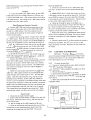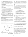
1
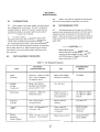
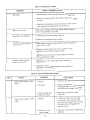
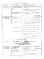
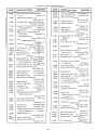
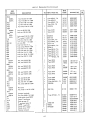
Table 5-2. Miscellaneous Troubles
CHECK - PROBABLE CAUSE
SYMPTOM
a. Check operating setup for ground loops (see Paragraph 5-22).
High ripple
b. Check main rectifiers (CR11, CR12, CR31, CR32, CR51, CR52)
for open.
c. Supply may be operating in current limit mode. Check current
limit adjustment, Paragraph 5-16, steps (k) thru (s).
Will not current limit
Check for open OR-gate diodes (CR5, CR25, CR45) or defective
current limit amplifier (U1, U2, U3).
Poor load or line regulation
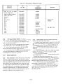
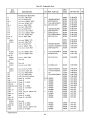
a. Check bias and reference voltages, Table 5-4.
b. Check main rectifiers and filters for opens.
a. High frequency oscillations (above 50 KHz) can be caused by an
open C4, C14, or C24.
Oscillation or poor transient
recovery time
b. A defective output capacitor (C1, C11, or C21) can cause
oscillations in one of many frequency ranges.
c. Oscillation only in the current limiting mode can be caused
by an open C3, C13, or C23.
a. Overshoot only in the -20V supply can be caused by a
shorted 013.
Transient voltage overshoot
at turn-on or turn-off.
b. Overshoot in all three supply outputs can be caused by an
open 014 or a shorted 015.
/
.
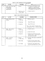
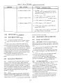
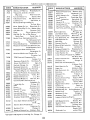
Table 5-3. Initial Troubleshooting Procedure
STEP
1
2
ACTION
Check output voltage of +20V
supply.
Check output voltage of -20V
supply.
RESPONSE
NEXT ACTION
q. Normal
a. Proceed to step (2).
b. Zero volts
b. Check ac line fuse (F1). If blown, proceed
to Paragraph 5·38. If not blown, check
bias and reference voltages (Table 5-4).
c. Output voltage lower
or higher than rating.
c. Check bias and reference voltages
(Table 5-4).
a. Normal
a. If +20V and -20V outputs are both
normal with no load, a supply might
be current limiting under load. To check
this adjustment see Paragraph 5-16,
steps (k) thru (0).
b. High, low, or zero
output voltage.
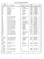
b. Proceed to -20V supply troubleshooting,
Table 5-6.
5-7