1
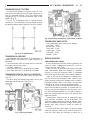
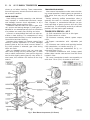
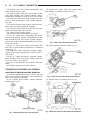
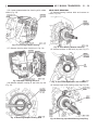
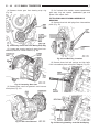
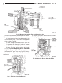
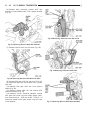
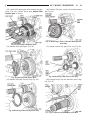
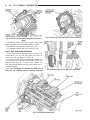
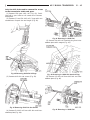
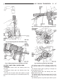
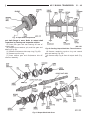
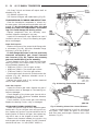
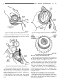
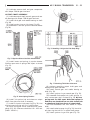
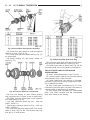
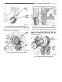
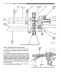
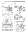
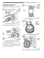
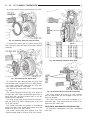
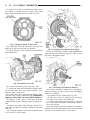
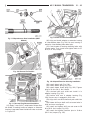
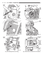
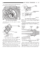
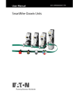
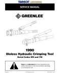
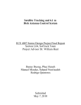
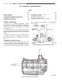
21 - 32
AX 15 MANUAL TRANSMISSION
J
AX 15 MANUAL TRANSMISSION
INDEX
page
General Information . . . . . . . . . . . . . . .
Service Diagnosis . . . . . . . . . . . . . . . .
Transmission Assembly and Adjustment
Transmission Disassembly and Overhaul
Transmission Gear Ratios . . . . . . . . . .
Transmission Identification . . . . . . . . . .
...
...
..
..
...
...
.
.
.
.
.
.
.
.
.
.
.
.
.
.
.
.
.
.
.
.
.
.
.
.
.
.
.
.
.
.
32
33
51
36
33
32
GENERAL INFORMATION
The AX 15 is a 5-speed, synchromesh, manual
transmission. Fifth gear is an overdrive range with a
ratio of 0.79:1. The shift mechanism is integral and
mounted in the shift tower portion of the adapter
housing (Fig. 1).
An adapter housing is used to attach the transmission to the transfer case on 4-wheel drive models. A
standard extension housing is used on 2-wheel drive
models.
The AX 15 is used in XJ and YJ models with a
4.0L engine. The AX 15 is designed for use with either two-wheel drive or four-wheel drive applications.
page
Transmission
Transmission
Transmission
Transmission
Transmission
Installation—AX 15 . . . . .
Lubricant . . . . . . . . . . . .
Removal—AX 15 . . . . . .
Shift Pattern . . . . . . . . . .
Switch and Plug Locations
.
.
.
.
.
.
.
.
.
.
.
.
.
.
.
.
.
.
.
.
.
.
.
.
.
.
.
.
.
.
.
.
.
.
35
33
34
33
33
ture. The next series of numbers is the transmission
serial number.
TRANSMISSION IDENTIFICATION
The AX 15 identification code numbers are on the
bottom surface of the transmission gear case (Fig. 2).
The first number is year of manufacture. The second and third numbers indicate month of manufac-
.
.
.
.
.
Fig. 2 Identification Code Number Location
Fig. 1 AX 15 Manual Transmission
AX 15 MANUAL TRANSMISSION
J
21 - 33
TRANSMISSION SHIFT PATTERN
The AX 15 shift pattern is shown in Figure 3. First
and second and third and fourth gear ranges are in
line for improved shifting. Fifth and reverse gear
ranges are also in line at the extreme right of the
pattern (Fig. 3).
The AX 15 is equipped with a reverse lockout
mechanism. The shift lever must be moved through
the Neutral detent before making a shift to reverse.
Fig. 5 Drain Plug And Backup Light Switch Location
TRANSMISSION GEAR RATIOS
Fig. 3 AX 15 Shift Pattern
TRANSMISSION LUBRICANT
Recommended lubricant for AX 15 transmissions is
Mopar 75W-90, API Grade GL-5 gear lubricant, or
equivalent.
Correct lubricant refill or top-off level is to the bottom edge of the fill plug hole.
Lubricant capacity is:
• 3.10 liters (3.27 qts.) in 4-wheel drive models.
• 3.15 liters (3.32 qts.) in 2-wheel drive models.
TRANSMISSION SWITCH AND PLUG LOCATIONS
The fill plug is at the driver side of the gear case
(Fig. 4).
The drain plug and backup light switch are on the
passenger side of the gear case (Fig. 5).
Fig. 4 Fill Plug Location
The transmission gear ratios are as follows:
First gear - 3.83:1
Second gear - 2.33:1
Third gear - 1.44:1
Fourth gear - 1.00:1
Fifth gear - 0.79:1
Reverse - 4.22:1
SERVICE DIAGNOSIS
LOW LUBRICANT LEVEL
A low transmission lubricant level is generally the
result of a leak, inadequate lubricant fill, or an incorrect lubricant level check.
Leaks can occur at the mating surfaces of the gear
case, intermediate plate and adapter or extension
housing, or from the front/rear seals. A suspected
leak could also be the result of an overfill condition.
Leaks at the rear of the extension or adapter housing will be from the housing oil seals. Leaks at component mating surfaces will probably be the result of
inadequate sealer, gaps in the sealer, incorrect bolt
tightening, or use of a non-recommended sealer.
A leak at the front of the transmission will be from
either the front bearing retainer or retainer seal. Lubricant may be seen dripping from the clutch housing after extended operation. If the leak is severe, it
may also contaminate the clutch disc causing slip,
grab and chatter.
Transmissions filled from air or electrically powered lubricant containers can be underfilled. This
generally happens when the container delivery mechanism is improperly calibrated. Always check the lubricant level after filling to avoid an under fill
condition.
A correct lubricant level check can only be made
when the vehicle is level; use a drive-on hoist to ensure this. Also allow the lubricant to settle for a
21 - 34
AX 15 MANUAL TRANSMISSION
minute or so before checking. These recommendations will ensure an accurate check and avoid an under-or-overfill condition.
HARD SHIFTING
Hard shifting is usually caused by a low lubricant
level, improper or contaminated lubricants, component damage, incorrect clutch adjustment, or by a
damaged clutch pressure plate or disc.
Substantial lubricant leaks can result in gear, shift
rail, synchro and bearing damage. If a leak goes undetected for an extended period, the first indications
of a problem are usually hard shifting and noise.
Incorrect or contaminated lubricants can also contribute to hard shifting. The consequence of using
non-recommended lubricants is noise, excessive wear,
internal bind and hard shifting.
Improper clutch release is a frequent cause of hard
shifting. Incorrect adjustment or a worn, damaged
pressure plate or disc can cause incorrect release. If
the clutch problem is advanced, gear clash during
shifts can result.
Worn or damaged synchro rings can cause gear
clash when shifting into any forward gear. In some
new or rebuilt transmissions, new synchro rings may
tend to stick slightly causing hard or noisy shifts. In
most cases, this condition will decline as the rings
wear-in.
J
TRANSMISSION NOISE
Most manual transmissions make some noise during normal operation. Rotating gears can generate a
mild whine that may only be audible at extreme
speeds.
Severe, obviously audible transmission noise is
generally the result of a lubricant problem. Insufficient, improper, or contaminated lubricant can promote rapid wear of gears, synchros, shift rails, forks
and bearings. The overheating caused by a lubricant
problem, can also lead to gear breakage.
TRANSMISSION REMOVAL—AX 15
(1) Shift transmission into first or third gear.
(2) Raise vehicle on a hoist.
(3) Disconnect necessary exhaust system components.
(4) Support transmission with adjustable jack
stand.
(5) Disconnect rear cushion and mounting bracket
from transmission, or transfer case (Fig. 1).
(6) On XJ, remove rear crossmember. On YJ, remove skid plate (Fig. 1).
(7) Disconnect transmission shift linkage, speedometer cable, transfer case vacuum lines and clutch
hydraulic lines.
(8) Lower transmission-transfer case assembly no
more than 7.6 cm (3 in.) for access to shift lever.
Fig. 1 Rear Mount Components (YJ Shown)
AX 15 MANUAL TRANSMISSION
J
21 - 35
(9) Reach up and around transmission case and
unseat shift lever dust boot from transmission shift
tower (Fig. 2). Move boot upward on shift lever for
access to lever retainer.
(10) Disengage shift lever as follows:
(a) Reach up and around transmission case and
press shift lever retainer downward with your fingers.
(b) Turn retainer counterclockwise to release it.
(c) Lift lever and retainer out of shift tower (Fig.
2). It is not necessary to remove shift lever
from floorpan boot. Simply leave lever in
place for later installation.
Fig. 4 Timing Sensor Location
Fig. 2 Removing/Installing Shift Lever
(11) Mark front and rear propeller shafts for installation alignment (Fig. 3). Then remove both
shafts.
Fig. 3 Marking Propeller Shaft And Axle Yoke
(12) Remove crankshaft position/engine timing sensor (Fig. 4).
(13) Disconnect transmission and transfer case
vent hoses.
(14) Remove slave cylinder from clutch housing.
(15) Support transmission-transfer case assembly
with transmission jack. Secure assembly to jack with
safety chains.
(16) Reposition adjustable jack stand under engine.
Be sure to place wood block between jack and oil
pan.
(17) Remove clutch housing brace rod.
(18) Remove clutch housing-to-engine bolts and remove transmission-transfer case assembly.
(19) Remove bolts attaching transmission to transfer case and separate components.
(20) Remove release bearing, fork and retainer
clip.
(21) Remove clutch housing from transmission.
TRANSMISSION INSTALLATION—AX 15
(1) Install clutch housing on transmission. Tighten
housing bolts to 37 Nzm (27 ft-lbs) torque.
(2) Lubricate contact surfaces of release fork, lever
and pivot ball stud. Then install bearing, fork and
clip in clutch housing.
(3) Mount transmission on transmission jack. Secure transmission with safety chains.
(4) Lightly lubricate pilot bearing and transmission input shaft splines with Mopar high temperature grease.
(5) Align transmission input shaft and clutch disc
splines and install transmission.
(6) Install and tighten clutch housing-to-engine
bolts to 38 Nzm (28 ft. lbs.) torque. Be sure housing
is properly seated on engine before tightening
bolts.
(7) Lower transmission no more than 7.6 cm (3 in.)
for access to the shift tower.
(8) Reach up and around the transmission and insert shift lever in shift tower. Press lever retainer
downward and turn it clockwise to lock it in place.
Then install lever dust boot on shift tower.
(9) Connect engine timing sensor.
21 - 36
AX 15 MANUAL TRANSMISSION
(10) Remove jack from under transmission and
mount transfer case on jack.
(11) Align transfer case and transmission shafts
and install transfer case. Tighten transfer case-totransmission nuts/bolts to 35 Nzm (26 ft. lbs.) torque.
(12) Move jack stand from under engine and reposition it under transmission. Then remove transmission jack.
(13) Connect transfer case vacuum hoses and linkage. Check and adjust linkage if necessary.
(14) Connect transmission and transfer case vent
hoses and backup light switch wires.
(15) Install clutch sleeve cylinder.
(16) Connect vehicle speed sensor and wires.
(17) On XJ, install rear crossmember and attach
cushion and bracket. Tighten crossmember-to-frame
bolts to 41 Nzm (30 ft. lbs.) torque. Tighten transmission-to-rear cushion and bracket bolts/nuts to 45 Nzm
(33 ft. lbs.) torque.
(18) On YJ, install rear cushion and bracket and
skid plate. Tighten attaching bolts/nuts to indicated
torque (Fig. 1).
(19) Align and install front/rear propeller shafts.
Tighten shaft U-joint clamp bolts to 19 Nzm (170 in.
lbs.) torque.
(20) On XJ, install skid plate if removed. Tighten
bolts to 42 Nzm (31 ft. lbs.) torque. Tighten stud nuts
to 17 Nzm (150 in. lbs.) torque.
(21) Top off transmission and transfer lubricant
levels.
(22) Remove supports and lower vehicle.
J
(3) Remove shift tower bolts and remove tower
from adapter or extension housing (Fig. 2).
Fig. 2 Shift Tower Removal/Installation
(4) Remove gasket from shift tower (Fig. 3).
TRANSMISSION DISASSEMBLY AND OVERHAUL
ADAPTER/EXTENSION HOUSING REMOVAL
(1) Remove release bearing, fork, retainer clip and
clutch housing from transmission. Also remove shift
lever if not previously removed.
(2) On 2-wheel drive models, remove extension
housing seal (Fig. 1).
Fig. 1 Removing Extension Housing Seal
Fig. 3 Shift Tower Gasket Removal/Installation
(5) Remove shift arm retainer bolt (Fig. 4).
Fig. 4 Shift Arm Retainer Bolt Removal/Installation
AX 15 MANUAL TRANSMISSION
J
(6) Loosen and remove restrictor pins (Fig. 5).
Fig. 5 Removing/Installing Restrictor Pins
(7) Remove shift arm shaft plug (Fig. 6).
21 - 37
(9) Remove shift arm (Fig. 8).
Fig. 8 Shift Arm Removal/Installation
(10) Remove plug for reverse shift head lock ball.
Plug is at right side of adapter housing near backup
light switch (Fig. 9).
Fig. 6 Removing/Installing Shift Lever Shaft Plug
(8) Remove shift arm shaft with large magnet (Fig.
7).
Fig. 7 Removing/Installing Shift Lever Shaft
Fig. 9 Removing/Installing Lock Ball Plug
21 - 38
AX 15 MANUAL TRANSMISSION
J
(11) Remove lock ball spring with pencil magnet
(Fig. 10).
Fig. 10 Removing/Installing Lock Ball Spring
(12) Remove shift head lock ball with pencil magnet (Fig. 11).
Fig. 11 Removing/Installing Shift Head Lock Ball
(13) Remove backup light switch from adapter/extension housing.
(14) On 2-wheel drive models, remove distance
sensor, speedometer adapter and driven gear if not
removed previously.
(15) Remove adapter/extension housing bolts (Fig.
12).
Fig. 12 Adapter Housing Bolt Locations
AX 15 MANUAL TRANSMISSION
J
(16) Loosen adapter/extension housing with rubber
mallet (Fig. 13).
21 - 39
GEAR CASE REMOVAL
(1) Remove bearing retainer bolts and remove retainer (Fig. 16).
Fig. 13 Loosening Adapter Housing
(17) Remove housing after loosening it (Fig. 14)
Fig. 16 Front Bearing Retainer Removal
(2) Remove retainer oil seal with pry tool (Fig. 17).
Fig. 14 Adapter Housing Removal
(18) Remove adapter housing oil seal with pry tool
(Fig. 15).
Fig. 15 Removing Adapter Housing Seal
Fig. 17 Front Bearing Retainer Seal Location
(3) Remove input shaft bearing snap ring (Fig. 18).
Fig. 18 Removing Input Shaft Bearing Snap Ring
21 - 40
AX 15 MANUAL TRANSMISSION
(4) Remove cluster gear front bearing snap ring
(Fig. 19).
J
(7) On 2-wheel drive models, remove speedometer
gear snap ring and remove speedometer gear and
spacer from output shaft.
FIFTH GEAR AND SYNCHRO ASSEMBLY
REMOVAL
(1) Remove three lock ball plugs from intermediate
plate (Fig. 22).
Fig. 19 Removing Cluster Gear Front Bearing Snap Ring
(5) Loosen gear case by tapping it away from intermediate plate with rubber mallet (Fig. 20).
Fig. 22 Lock Ball Plug Locations
(2) Remove three lock ball springs and lock balls
from intermediate plate with pencil magnet (Fig. 23).
Fig. 20 Loosening Gear Case
(6) Remove gear case from geartrain and intermediate plate (Fig. 21).
Fig. 21 Gear Case Removal
Fig. 23 Removing/Installing Lock Ball And Spring
AX 15 MANUAL TRANSMISSION
J
21 - 41
Fig. 24 Mounting Intermediate Plate And Geartrain In Vise
(3) Mount intermediate plate and geartrain assembly in vise as follows:
(a) Insert two spare bolts in one bottom bolt hole
in intermediate plate. Insert bolts from opposite
sides of plates (Fig. 24).
(b) Install enough flat washers under each bolt
head to prevent bolts from touching (Fig. 24).
(c) Tape bolts and washers in place and mount
intermediate plate in vise (Fig. 24).
(d) Clamp vise jaws securely against bolt heads
(Fig. 24). Do not clamp vise jaws on intermediate plate. Clamp only on bolt heads.
(4) Remove fifth gear snap ring (Fig. 25). Retain
snap ring for assembly reference. It is a select fit
component.
(5) Remove E-ring that secures reverse shift arm
to fork (Fig. 26).
Fig. 26 Removing Reverse Shift Arm E-Ring
Fig. 25 Fifth Gear Snap Ring Removal
21 - 42
AX 15 MANUAL TRANSMISSION
J
(6) Remove bolts attaching reverse shift arm
bracket to intermediate plate. Then remove bracket
(Fig. 27).
Fig. 29 Removing Fifth Gear Fork Set Screw
Fig. 27 Removing Reverse Shift Arm Bracket
(7) Remove reverse shift arm and shoe (Fig. 28).
Fig. 30 Removing Fifth Gear Shift Fork
Fig. 28 Removing Reverse Shift Arm And Shoe
(8) Remove fifth gear shift fork set screw (Fig. 29).
(9) Move fifth gear shift rail forward until it clears
shift fork.
(10) Remove fifth gear shift fork from synchro
sleeve (Fig. 30).
(11) Remove reverse shift rail and reverse shift
head as assembly (Fig. 31).
(12) Measure thrust clearance between counter
fifth gear and thrust ring with feeler gauge. Clearance should be 0.10 - 0.40 mm (0.003 - 0.019 in.). If
clearance exceeds limits, gear and/or ring will have
to be replaced.
Fig. 31 Removing Reverse Shift Head And Rail
AX 15 MANUAL TRANSMISSION
J
(13) Loosen fifth spline gear with standard two-jaw
puller (Fig. 32). Position puller jaws behind fifth
counter gear as shown.
Fig. 32 Loosening Fifth Spline Gear
(14) Remove fifth spline gear (Fig. 33).
Fig. 33 Removing Fifth Spline Gear
(15) Remove fifth gear synchro ring (Fig. 34).
21 - 43
(16) Remove fifth gear synchro and sleeve assembly (Fig. 35).
Fig. 35 Removing Counter Fifth Gear And Synchro
Assembly
(17) Remove counter fifth gear thrust ring (Fig. 36).
Fig. 36 Removing Fifth Gear Thrust Ring
(18) Remove thrust ring lock ball with pencil magnet (Fig. 37).
Fig. 34 Removing Fifth Gear Synchro Ring
Fig. 37 Removing Thrust Ring Lock Ball
21 - 44
AX 15 MANUAL TRANSMISSION
Fig. 38 Removing Output Shaft Rear Bearing Retainer
Bolts
J
Fig. 39 Removing Output Shaft Rear Bearing Retainer
(19) Remove bolts attaching output shaft rear
bearing retainer to intermediate plate (Fig. 38).
(20) Remove rear bearing retainer (Fig. 39).
(21) Remove reverse gear and shaft (Fig. 40).
SHIFT RAIL AND FORK REMOVAL
There are a total of five shift rails in the AX 15
transmission. The 1-2, 3-4, fifth gear and front reverse shift rails are shown in Figure 41.
Two shift rails are used for reverse gear range. The
front reverse rail is at the forward side of the intermediate plate (Fig. 41). The short rear reverse rail
and reverse shift head are at the rear side of the intermediate plate.
It is not necessary to remove the shift rails if
they do not require service during overhaul.
Fig. 40 Removing Reverse Idler Gear And Shaft
Fig. 41 Shift Rail Identification
AX 15 MANUAL TRANSMISSION
J
21 - 45
Only the shift forks need be removed for access
to the transmission shafts and gears.
(1) Remove fifth gear shift rail (Fig. 41). Catch
lock ball in your hand as rail comes out of intermediate plate.
(2) Remove 1-2 and 3-4 shift rail C-rings with two
screwdrivers of equal size and length (Fig. 42).
Fig. 44 Removing 3-4 Shift Rail
(5) Remove 3-4 shift rail interlock plug from intermediate plate with magnet (Fig. 45).
Fig. 42 Removing Shift Rail C-Rings
(3) Remove shift fork set screws (Fig. 43).
Fig. 45 Removing 3-4 Shift Rail Interlock Plug
(6) Remove 1-2 shift rail from shift fork and intermediate plate (Fig. 46).
Fig. 43 Removing Shift Fork Set Screws
(4) Remove 3-4 shift rail from shift fork and intermediate plate (Fig. 44).
Fig. 46 Removing 1-2 Shift Rail
21 - 46
AX 15 MANUAL TRANSMISSION
(7) Remove 1-2 shift rail interlock pin from shift
rail (Fig. 47).
J
(10) Remove 3-4 shift fork (Fig. 50).
(11) Remove 1-2 shift fork (Fig. 50).
Fig. 47 Removing 1-2 Shift Rail Interlock Pin
(8) Remove 1-2 shift rail interlock plug from intermediate plate (Fig. 48).
Fig. 50 Shift Fork Removal
Fig. 48 Removing 1-2 Shift Rail Interlock Plug
(9) Lift reverse shift fork upward and remove fifth
gear shift rail lock ball (Fig. 49).
Fig. 49 Removing Fifth Gear Shift Rail Lock Ball
(12) Remove reverse shift rail C-ring with two
equal length and size screwdrivers (Fig. 51).
(13) Remove reverse shift rail and fork (Fig. 52).
(14) Remove interlock pin from reverse shift rail
(Fig. 53).
(15) Position shift rails, shift forks, lock balls, interlock plugs and interlock pins on the workbench in
order of removal. This will help in identifying components during inspection and assembly.
AX 15 MANUAL TRANSMISSION
J
21 - 47
Fig. 53 Removing Reverse Shift Rail Interlock Pin
Fig. 51 Removing Reverse Shift Rail C-Ring
Fig. 52 Removing Reverse Shift Rail And Fork
Fig. 54 Removing Bearing Snap Rings
OUTPUT SHAFT AND CLUSTER GEAR
REMOVAL
(1) Remove output shaft rear bearing snap ring
(Fig. 54).
(2) Remove cluster gear rear bearing snap ring
(Fig. 54).
(3) Tap end of output shaft with mallet to unseat
and start rear bearing out of intermediate plate (Fig.
55).
(4) Remove output shaft by rocking it lightly until
rear bearing comes out of intermediate plate (Fig.
56).
(5) Remove cluster gear by pulling it straight out
of rear bearing (Fig. 57).
(6) Remove cluster gear rear bearing from intermediate plate (Fig. 58).
(7) Remove input shaft from output shaft (Fig. 59).
(8) Remove output shaft pilot bearing from input
shaft (Fig. 60).
(9) Remove synchro ring from input shaft (Fig. 61).
21 - 48
AX 15 MANUAL TRANSMISSION
J
Fig. 55 Unseating Output Shaft Rear Bearing
Fig. 58 Removing Cluster Gear Rear Bearing
Fig. 56 Input/Output Shaft Assembly Removal
Fig. 59 Input Shaft Removal
Fig. 57 Cluster Gear Removal
Fig. 60 Removing Input Shaft Pilot Bearing
(10) Remove bearing snap ring and press bearing
off input shaft (Fig. 61).
• First gear clearance should be 0.10 - 0.40 mm
(0.003 - 0.0197 in).
• Second—third gear clearance should be 0.10 - 0.30
mm (0.003 - 0.0118 in.).
(2) If first gear thrust clearance is incorrect, replace
gear and thrust washer. If second or third gear clearance is incorrect, either gear and bearing, or out-
OUTPUT SHAFT DISASSEMBLY
(1) Measure thrust clearance of output shaft first,
second and third gears with feeler gauge (Fig. 62).
AX 15 MANUAL TRANSMISSION
J
21 - 49
Fig. 61 Input Shaft Components
put shaft flange is worn. Refer to output shaft
inspection in Cleaning and Inspection section.
(3) Press fifth gear and rear bearing off rear of
output shaft.
(4) Remove thrust washer, pin, and first gear and
bearing (Fig. 62).
(5) Remove first/reverse hub snap ring (Fig. 63).
(6) Remove synchro ring.
(7) Press reverse gear and first/reverse hub off
shaft as assembly.
Fig. 62 Checking Output Shaft Gear Thrust Clearance
(8) Remove remaining synchro ring and second
gear and bearing (Fig. 63).
(9) Remove snap ring at front of output shaft (Fig.
63).
Fig. 63 Output Shaft And Gears
21 - 50
AX 15 MANUAL TRANSMISSION
J
(10) Press 3-4 hub and sleeve off output shaft as
assembly (Fig. 63).
(11) Remove synchro ring.
(12) Remove third gear and needle bearing (Fig. 63).
TRANSMISSION CLEANING AND INSPECTION
Clean the transmission components in solvent. Dry
the cases, gears, shift mechanism and shafts with compressed air. Dry the bearings with clean, dry shop
towels only. Never use compressed air on the bearings. This could damage the bearing rollers.
Replace components that are obviously worn,
cracked, chipped or damaged in any way.
Inspect the transmission case. Replace the case if
cracked or porous or if any of the bearing and gear
bores are damaged.
Output Shaft Inspection
Measure thickness of the output shaft flange with
a micrometer (Fig. 64). Minimum allowable flange
thickness is 4.70 mm (0.185 in).
If shaft flange thickness is OK but previously
measured second/third gear thrust clearance
was incorrect (Fig. 62), replace the necessary
gear and needle bearing as an assembly.
Check diameter of the first, second and third gear
bearing surfaces of the output shaft (Fig. 64). Minimum allowable diameters are:
• 38.86 mm (1.529 in.) for first gear surface
• 46.86 mm (1.844 in.) for second gear surface
• 37.86 mm (1.490 in.) for third gear surface
Check output shaft runout with V-blocks and a dial
indicator (Fig. 64). Maximum allowable runout is
0.06 mm (0.0024 in.).
Replace the output shaft if any surface measured
fails to meet stated tolerance.
Fig. 64 Checking Output Shaft Tolerances
Cluster Gear Inspection
Inspect the cluster gear teeth. Replace the gear if
any teeth are worn or damaged or if the bearing surfaces are damaged.
Check diameter of the cluster gear journal with a
micrometer (Fig. 65). Minimum allowable diameter
is 27.860 mm (1.096 in.).
Check condition of the cluster gear front bearing.
Replace the bearing if worn, noisy, or damaged.
GEAR AND SYNCHRO INSPECTION
Install the synchro rings on their respective gears.
Rotate each ring on the gear and note synchro action. Replace any synchro ring that exhibits a lack of
braking action or binds on the gear. Also replace any
ring that is worn or has chipped or broken teeth.
Measure end clearance between the synchro ring
and the gear with a feeler gauge (Fig. 66). Clearance
should be 0.06 mm - 1.6 mm (0.024 - 0.063 in.).
Fig. 65 Checking Cluster Gear Journal Diameter
Install the needle bearings in the first, second and
third gears. Then install the gears on the output
shaft and check shaft-to-gear clearance with a dial
indicator (Fig. 67).
AX 15 MANUAL TRANSMISSION
J
Fig. 66 Checking Synchro Ring End Clearance
21 - 51
Fig. 68 Checking Shift Fork-To-Sleeve Clearance
Maximum allowable clearance is 0.16 mm (0.0063
in.). If any gear exhibits excessive clearance, replace
the gear and needle bearing.
Fig. 69 Reverse Idler Gear Bushing
Fig. 67 Checking Gear-To-Shaft Clearance
Check clearance between the shift forks and synchro sleeves with a feeler gauge (Fig. 68). Clearance
should not exceed 1.0 mm (0.039 in.). Replace the
synchro sleeve (and matching hub) if clearance exceeds the stated limit.
Check condition of the reverse idler gear bushing
(Fig. 69). Replace the gear if the bushing is damaged or
worn.
Gear Case, Housing And Intermediate Plate
Clean the case, housing and plate with solvent and
dry with compressed air. Replace any component that
is cracked, warped or damaged in any way.
Inspect the threads in the case, housing and plate.
Minor thread damage can be repaired with steel thread
inserts if necessary. However, do not attempt to repair
if the cracks are evident around any threaded hole.
Inspect the reverse pin in the adapter/extension
housing. Replace the pin if worn or damaged. Refer
to the replacement procedure in the Transmission
Assembly section.
TRANSMISSION ASSEMBLY AND ADJUSTMENT
Lubricate the transmission components with Mopar
75W-90 gear lubricant during assembly. Use petroleum jelly to lubricate seal lips and/or hold parts in
place during installation.
21 - 52
AX 15 MANUAL TRANSMISSION
FRONT BEARING, SEAL AND PIN
INSTALLATION
(1) Press front bearing on input shaft. Then secure
bearing with thickest snap ring that will fit in shaft
groove (Fig. 70).
J
(3) Install new oil seals in front bearing retainer and
adapter housing (Fig. 72). Installation depth for bearing
retainer seal is 10.5 - 11.5 mm (0.414 - 0.453 in.).
Fig. 70 Selecting Input Shaft Front Bearing Snap
Ring
(2) Press front bearing on cluster gear. Then secure bearing with thickest snap ring that will fit in
ring groove on gear (Fig. 71).
Fig. 72 Oil Seal Installation
(4) Install reverse shaft and shaft retaining pin in
adapter housing. Then install access hole plug with
torx bit (Fig. 73).
Fig. 71 Selecting Cluster Gear Front Bearing Snap
Ring
Fig. 73 Installing Reverse Shaft Pin
AX 15 MANUAL TRANSMISSION
J
21 - 53
(5) Lubricate reverse shaft and gear components
with Mopar 75W-90 gear lubricant.
OUTPUT SHAFT ASSEMBLY
(1) Lubricate output shaft journals, gears and needle bearings with Mopar 75W-90 gear lubricant.
(2) Install third gear and needle bearing on shaft
(Fig. 63)
(3) Install synchro ring on third gear (Fig. 63).
(4) Assemble 1-2 and 3-4 synchro hubs and sleeves
(Fig.74).
Fig. 76 Installing 3-4 Synchro Hub Snap Ring
Fig. 74 Synchro Sleeve And Hub Identification
(5) Install inserts and springs in synchro sleeves.
Position open ends of springs 180° apart as shown
(Fig. 75).
Fig. 77 Checking Third Gear Clearance
Fig. 75 Insert Spring Position
(6) Install 3-4 synchro hub and sleeve on output
shaft. Press hub onto shaft if necessary.
(7) Install 3-4 synchro hub snap ring (Fig. 76). Use
thickest snap ring that will fit in shaft groove.
(8) Verify third gear thrust clearance with feeler
gauge (Fig. 56). Clearance should be 0.10 - 0.25 mm
(0.004 - 0.010 in.).
(9) Lubricate remaining output shaft gears and
bearings with gear lubricant.
(10) Install second gear and needle bearing on
shaft (Fig. 78).
(11) Install synchro ring on second gear (Fig. 78).
(12) Assemble first/reverse hub, insert springs, inserts, reverse gear and 1-2 sleeve (Fig. 78). Be sure
spring ends are 180° apart. Note that splines in
hub bore are chamfered on one side. Install hub
so chamfered side faces front of output shaft.
(13) Press assembled hub and sleeve on output
shaft.
(14) Install selective snap ring (Fig. 78). Use thickest snap ring that will fit in output shaft groove.
(15) Install synchro ring on first gear (Fig. 79).
21 - 54
AX 15 MANUAL TRANSMISSION
J
Fig. 78 Second Gear And Synchro Assembly
(16) Install first gear spacer on shaft and against
selective fit snap ring (Fig. 79).
(17) Install first gear and needle bearing (Fig. 79)
on output shaft.
(18) Install locating pin and thrust washer on
shaft (Fig. 79).
Fig. 80 Selecting Fifth Gear Snap Ring
(22) Lubricate input shaft pilot bearing with petroleum jelly and install bearing in shaft (Fig. 60).
(23) Install input shaft on output shaft (Fig. 59). Be
sure output shaft hub is fully seated in pilot bearing.
Fig. 79 First And Fifth Gear Components
(19) Press rear bearing on shaft. Position bearing
snap ring groove so it is closest to end of output shaft.
(20) Check first and second gear thrust clearance
with feeler gauge (Fig. 62).
• First gear clearance should be 0.10 - 0.40 mm
(0.003 - 0.0197 in.)
• Second gear clearance should be 0.10 - 0.30 mm
(0.003 - 0.0118 in.)
(21) Press fifth gear onto output shaft. Then install
select fit snap ring (Fig. 80). Use thickest snap ring
that will fit in shaft groove.
OUTPUT SHAFT AND CLUSTER GEAR
INSTALLATION
(1) Mount intermediate plate in vise (Fig. 24).
(2) Lubricate cluster gear journal and rear bearing
with petroleum jelly or gear lubricant.
(3) Install cluster gear rear bearing in intermediate plate (Fig. 81). Be sure snap ring groove in bearing is rearward as shown.
(4) Start cluster gear into bearing (Fig. 57). Then
hold bearing and push gear into place. Use plastic or
rawhide mallet to seat bearing if necessary.
(5) Start output shaft rear bearing in intermediate
plate. Push shaft rearward and tap intermediate
plate with mallet to seat bearing.
AX 15 MANUAL TRANSMISSION
J
21 - 55
(7) Install reverse idler gear and shaft (Fig. 83).
Fig. 81 Installing Cluster Gear Rear Bearing
(6) Install snap rings on cluster and output shaft
rear bearings only (Fig. 82). Do not install front
bearing snap rings at this time.
Fig. 83 Installing Reverse Idler Gear And Shaft
(8) Position rear bearing retainer over output shaft
and rear bearing. Be sure bearing retainer tab is
engaged in reverse idler shaft notch (Fig. 84).
(9) Install and tighten rear bearing retainer bolts
to 18 Nzm (13 ft-lbs).
Fig. 82 Installing Rear Bearing Snap Rings
Fig. 84 Installing Rear Bearing Retainer
21 - 56
AX 15 MANUAL TRANSMISSION
J
Fig. 85 Shift Rail Ball-Plug-Pin Position
SHIFT RAIL AND FORK INSTALLATION
The shift rail interlock pins, balls and plugs must
be installed in the correct sequence for proper shifting. Refer to the installation diagram (Fig. 85) during assembly.
Coat the intermediate plate shift rail bores and
the interlock balls, pins and plugs with a heavy
coating of petroleum jelly before assembly. The
jelly will hold the interlock components in place
making installation easier. Use a pencil magnet
to hold and insert the interlocks. Then use a
small screwdriver to push the interlock components into place.
(1) Coat reverse rail interlock pin with petroleum
jelly and install pin in rail (Fig. 86).
Fig. 86 Installing Reverse Shift Rail Interlock Pin
AX 15 MANUAL TRANSMISSION
J
21 - 57
(2) Install reverse shift rail in intermediate plate
(Fig. 87).
(3) Install reverse shift rail C-ring (Fig. 51).
Fig. 89 Installing Reverse Shift Rail Lock Ball
Fig. 87 Installing Reverse Shift Rail And Fork
(6) Coat 1-2 shift rail interlock plug with petroleum jelly and install it in intermediate plate bore
(Fig. 90).
(4) Position 1-2 and 3-4 shift forks in synchro
sleeves (Fig. 88).
Fig. 90 Installing 1-2 Shift Rail Interlock Plug
(7) Coat 1-2 shift rail interlock pin with petroleum
jelly and insert it in shift rail (Fig. 91).
Fig. 88 Shift Fork Installation
(5) Coat reverse rail lock ball with petroleum jelly.
Then tilt reverse shift fork upward and insert ball in
intermediate plate (Fig. 89).
Fig. 91 Installing 1-2 Shift Rail Interlock Pin
21 - 58
AX 15 MANUAL TRANSMISSION
J
(8) Install 1-2 shift rail in intermediate plate and
1-2 fork (Fig. 92).
Fig. 94 Installing 3-4 Shift Rail
Fig. 92 Installing 1-2 Shift Rail
(9) Coat 3-4 shift rail interlock plug with petroleum jelly and install plug in intermediate plate (Fig.
93).
Fig. 95 Installing Shift Fork Set Screws
Fig. 93 Installing 3-4 Shift Rail Interlock Plug
(10) Install 3-4 shift rail in intermediate plate and
in both shift forks (Fig. 94).
(11) Verify that none of interlock balls, plugs, or
pins were displaced during shift rail installation.
(12) Install and tighten shift fork setscrews to 20
Nzm (14 ft. lbs.) torque (Fig. 95).
(13) Install 1-2 and 3-4 shift rail C-rings (Fig. 96).
(14) Insert fifth gear shift rail through reverse
shift fork. Then slide rail into intermediate plate
just far enough to secure interlock ball. Do not
fully install shift rail at this time.
Fig. 96 Installing Shift Rail C-Rings
AX 15 MANUAL TRANSMISSION
J
21 - 59
FIFTH-REVERSE GEAR AND SHIFT
COMPONENT INSTALLATION
(1) Install thrust ring lock ball in cluster gear
journal (Fig. 97). Use petroleum jelly to hold ball in
place.
Fig. 99 Assembling Fifth Gear And Synchro
Assembly
Fig. 97 Installing Thrust Ring Lock Ball
(2) Install fifth gear thrust ring (Fig. 98). Be sure
thrust ring notch fits over lock ball.
Fig. 100 Installing Counter Fifth Gear Bearing
Fig. 98 Installing Fifth Gear Thrust Ring
(3) Assemble counter fifth gear, synchro sleeve, inserts and insert springs (Fig. 99).
(4) Lubricate two-piece bearing with petroleum
jelly and install it in counter fifth gear (Fig. 100).
(5) Install counter fifth gear and synchro assembly
on cluster gear journal (Fig. 101).
Fig. 101 Installing Counter Fifth Gear And Sleeve
21 - 60
AX 15 MANUAL TRANSMISSION
J
(6) Install synchro ring in synchro sleeve (Fig. 102).
Fig. 102 Installing Fifth Gear Synchro Ring
(7) Install fifth spline gear on cluster journal (Fig.
103). Tap spline gear into place with plastic mallet if
necessary.
Fig. 104 Installing Fifth Gear Snap Ring
Fig. 103 Installing Fifth Spline Gear
(8) Install fifth gear selective snap ring (Fig. 104).
Use thickest snap ring that will fit in shaft groove.
(9) Install reverse shift head and rail (Fig. 105).
Then install lock ball in shift head.
(10) Position fifth gear shift fork in synchro sleeve
(Fig. 106).
(11) Install fifth gear shift rail (Fig. 107). Slide rail
through fork, shift head, intermediate plate and reverse shift fork. Be sure interlock ball is not displaced during installation.
(12) Align screw holes in shift fork and rail and install set screw (Fig. 108). Tighten screw to 20 Nzm
(15 ft. lbs.) torque.
(13) Install lock balls and springs in intermediate
plate (Fig. 109). Then install and tighten lock ball
plugs to 19 Nzm (14 ft. lbs.) torque.
(14) Install reverse shift arm bracket (Fig. 110).
Tighten bracket bolts to 18 Nzm (13 ft. lbs.) torque.
Fig. 105 Installing Reverse Shift Head And Rail
(15) Install reverse shift arm (Fig. 110). Position
arm on reverse fork pin and engage it with pin on
shift arm bracket.
(16) Verify that shift arm shoe is engaged in reverse idler gear. Then secure shift arm to pin on reverse fork with new E-clip.
GEAR CASE AND ADAPTER INSTALLATION
(1) Dismount intermediate and gear assemblies
from vise.
AX 15 MANUAL TRANSMISSION
J
21 - 61
Fig. 106 Installing Fifth Gear Shift Fork
Fig. 109 Detent Ball And Spring Installation
Fig. 107 Installing Fifth Gear Shift Rail
Fig. 110 Reverse Shift Arm And Bracket Installation
Fig. 108 Shift Fork Set Screw Installation
(2) Clean mating surfaces of intermediate plate
and transmission gear case with wax and grease remover. Then wipe dry with a clean cloth.
21 - 62
AX 15 MANUAL TRANSMISSION
J
(3) Apply 3 mm (1/8 in.) wide bead of Mopar Gasket Maker to mating surface of gear case. Keep
sealer bead inside bolt holes as shown (Fig. 111).
Fig. 111 Applying Sealer To Gear Case
(4) Install gear case (Fig. 112). Align shift rails and
bearings in case and tap case into position.
(5) Verify that gear case is seated on intermediate
plate dowel pins.
Fig. 113 Installing Front Bearing Snap Rings
(12) On 2-wheel drive models, install speedometer
gear, lock ball and retaining rings (Fig. 115). Be sure
lock ball is engaged in gear.
Fig. 112 Installing Gear Case
(6) Install front bearing snap rings (Fig. 113).
(7) Clean gear case and front bearing retainer sealing surfaces with wax and grease remover. Then
wipe dry with a clean cloth.
(8) Install new seal in front bearing retainer. Then
lubricate seal lip with petroleum jelly. Installation
depth for seal is 10.5 - 11.5 mm (0.413 - 0.453 in.).
(9) Apply a 3 mm (1/8 in.) wide bead of Mopar
Gasket Maker to front bearing retainer sealing surface.
(10) Align and install front bearing retainer (Fig.
114). Be sure retainer is properly seated on case and
bearings.
(11) Install and tighten front bearing retainer bolts
to 17 Nzm (12 ft. lbs.) torque.
Fig. 114 Installing Front Bearing Retainer
(13) Inspect condition o reverse pin in adapter/extension housing (Fig. 116). If pin is worn or damaged,
replace it as follows:
(a) Remove roll pin access plug (Fig. 117).
(b) Tap roll pin out of housing with pin punch
(Fig. 118). Then remove old reverse pin.
(c) Install new reverse pin and secure it with roll
pin. Then install and tighten access plug to 19 Nzm
(14 ft. lbs.) torque.
(14) Clean sealing surfaces of adapter or extension
housing and intermediate plate with wax and grease
remover. Then wipe dry with a clean cloth.
AX 15 MANUAL TRANSMISSION
J
Fig. 115 Speedometer Gear Installation (2WD
Models)
21 - 63
Fig. 118 Roll Pin Removal/Installation
(16) Align and install adapter or extension housing
on intermediate plate (Fig. 119). Be sure housing is
seated on intermediate plate dowel pins.
(17) Coat threads of housing attaching bolts with
silicone sealer. Then install and tighten bolts to 37
Nzm (27 ft. lbs.) torque.
Fig. 116 Reverse Pin Position
Fig. 119 Adapter/Extension Housing Installation
Fig. 117 Access Plug Removal/Installation
(15) Apply 3 mm (1/8 in.) wide bead of Mopar Gasket Maker to sealing surface of adapter or extension
housing. Keep sealer bead inside bolt holes as shown
in Figure 111.
(18) Install detent ball (Fig. 120).
(19) Install detent spring (Fig. 121).
(20) Install detent access plug (Fig. 122). Tighten
plug to 19 Nzm (14 ft. lbs.) torque.
(21) Lubricate shift arm shaft and install it in
adapter housing (Fig. 123).
(22) Position shift arm in adapter housing (Fig.
124). Be sure arm is engaged in shift rails.
(23) Align shift arm with shaft and push shaft into
arm.
(24) Rotate shift arm shaft until set screw holes in
shaft and arm are aligned.
(25) Install and tighten shift arm set screw to 38
Nzm (28 ft. lbs.) torque (Fig. 125).
(26) Install and tighten restrictor pins to 19 Nzm
(14 ft. lbs.) torque (Fig. 125).
21 - 64
AX 15 MANUAL TRANSMISSION
J
Fig. 120 Installing Detent Ball
Fig. 123 Installing Shift Arm Shaft
Fig. 121 Installing Detent Spring
Fig. 124 Shift Arm Installation
Fig. 122 Installing Detent Access Plug
Fig. 125 Set Screw And Restrictor Pin Installation
AX 15 MANUAL TRANSMISSION
J
21 - 65
(27) Install and tighten shift arm shaft access plug
to 19 Nzm (14 ft. lbs.) torque (Fig. 126).
Fig. 128 Shift Tower Installation
Fig. 126 Access Plug Installation
(28) Position new shift tower gasket on adapter
housing (Fig 127).
position. Then fill with Mopar 75W-90, grade GL-5
gear lubricant. Correct fill level is to bottom edge of
fill plug hole.
(33) Install new washer on fill plug. Then install
and tighten plug to 37 Nzm (27 ft. lbs.) torque.
(34) Install clutch housing and release bearing
components.
Fig. 127 Shift Tower Gasket Installation
(29) Install shift tower (Fig. 128). Tighten tower
attaching bolts to 18 Nzm (13 ft. lbs.) torque.
(30) Install new gasket on backup light switch and
install switch. Tighten switch to 37 Nzm (27 ft. lbs.)
torque.
(31) Install new washer on drain plug. Then install
and tighten plug to 37 Nzm (27 ft. lbs.) torque.
(32) If transmission will be filled with gear lubricant before installation, place transmission in a level
Fig. 129 Installing Extension Housing Seal—2WD
Models
(35) On 2-wheel drive models, install new seal in
extension housing with suitable size installer tool
(Fig. 129). Lubricate seal lips with petroleum jelly
before installation.
(36) On 2-wheel drive models, install speedometer
driven gear (if removed), and vehicle speed sensor.