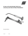
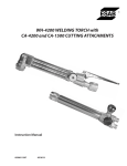
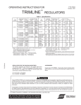
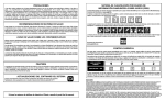
1
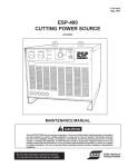
INSTRUCTIONS for ���������������� F14-253-C ���������� May, 2009 ������������� C-84-42 OXY-FUEL CUTTING TORCH ������������������������������ Cutting Range using acetylene.......................................... up to 5” ����������������������������������������� ����������������������������� other fuel gases......................... up �������� to 12” ���������������� ����������������������� ��������� Cutting Nozzles............................................................4200 series ��������������� ���������������������������������������������������������� ����������� Torch-Hose Connection..................... Oxy.CGA-022 (9/16”18) ��������������������� �������������������� ����������������������� F.G.CGA-023 (9/1618LH) ������������������������ Torch Overall Length............................................................. 21-in. �������������������� ����������������������������������������������������������� Weight.................................................................................. 38������ oz. ������ �������������������������������������������������������������������������������� ������ caution These INSTRUCTIONS are for experienced operators. If you are not fully familiar with the principles of operation ���������������������������������������������������������������������������������������������������������������� and safe practices for oxy-fuel gas equipment, we urge you to read our booklet “Precautions and Safe Practices ������������������������������������������������������������������������������������������������������������������ for Gas Welding, Cutting & Heating,” Form 2035. Do NOT permit untrained persons to install, operate, or maintain ����������������������������������������������������������������������������������������������������������������� this equipment. Do NOT attempt to install or operate this equipment until you have read and fully understand these ������������������������������������������������������������������������������������������������������������� instructions. If you do not fully understand these instructions, contact your supplier for further information. ��������������������������������������������������������������������������������������������������������������� The cutting torches covered by these instructions are listed by third parties only when using parts manufactured ���������������������������������������������������������������������������������������������������������������� by ESAB Welding & Cutting Products to the exact specifications on file with third party listed, and when they are ���������������������������������������������������������������������������������������������������������������� used in the gas service for which they are designed and listed. The use of other parts that cause damage or failure �������������������������������������������������������������������������������������������������������������������� to the equipment will void the manufacturer’s warranty. ������������������������������������������������������������������������������������ OPERATING INSTRUCTIONS ���������������������� CONNECTING 1.���������� Attach regulators to the oxygen and fuel gas �� cylinders. ��������������������������������������������������� Follow all instructions supplied with ����������������������������������������������������� the regulators. �������oxygen and fuel gas hoses to the regu2. Attach �� lators ����������������������������������������������� and to the torch, after making sure all �������������������������������������������������� metal seating surfaces are clean. Tighten all �������������������������������������������������� connection nuts with a wrench. ������������������� 3. Attach nozzle to torch head, and tighten con�� nection ������������������������������������������������ nut with a wrench. ����������������������� 4. Check throttle valve packing nuts for tight�� ness. ������������������������������������������������ WARNING ����������������������������������� Flashbacks can cause serious burns. ������������������������������������������������������� Be sure gas flow is sufficient for head or nozzle �������������������������������������������� size. �������������������������������� Adjust regulators for proper psig pressures. �������������������������� Adjust throttle valves properly. ������������������������������������������������������ Keep torch in good repair. ����������������� Be sure this information reaches the operator. You ���������������������������������������������� can get extra copies through your supplier. ����������������������������������������������� DO NOT throttle back gases to use large head or nozzle on thin material. ����������������� ������ �������� ������� ��� ����������� ������� ��� TESTING FOR ������� LEAKS ����������������������������������������������������������� Every cutting outfit should be thoroughly tested ������������������������������������������������������ for leaks after it is first hooked up, and at regular ��������������������������������������������������������� intervals thereafter. After all connections have been ��� ����make ���������� ��� made, sure������������������� all valves on the������� torch ������ handle ��������������������������������������������������� are closed. Then turn in the regulator pressure-ad������������������������������������������������������ justing screws until the oxygen delivery-pressure ����������������������������������������������������� gauge registers 60 psi and the fuel gas delivery����������������������������������������������������� pressure gauge registers 10 psi. Using Leak Test ��������������������������������������������������������� Solution suitable for oxygen service, such as P/N ������������������������������������������������������� 998771 (8 oz. container), check for leaks at the �������������������������������������������������������� cylinder valves, the cylinder-to-regulator connec���������������������������������������������������������� tions, the regulator-to-hose connections, and the ������������������������������������������������������� hose-to-torch connections. If bubbling at any point ����������������������������������������������������� indicates leakage, tighten the connection. If this ���� ������ ���� �������� ��������close ���� ���������� �������� does not stop the leakage, the appropriate ���������������������������������������������������� cylinder valve, open the corresponding torch valve to��������������������������������������������������� remove all pressure from the line, and finally �������������������������������������������������������� release the regulator pressure adjusting screw by ��������������������������������������������������� turning it counterclockwise. Then break the leaky �������������������������������������������������������������� connection, wipe metal seating surfaces with a �������������������������� READ AND UNDERSTAND INSTRUCTION MANUAL BEFORE INSTALLING OR OPERATING. PROTECT YOURSELF AND OTHERS! caution These INSTRUCTIONS are for experienced operators. If you are not fully familiar with the principles of operation and safe practices for gas welding and cutting equipment, we urge you to read our booklet, “Precautions and Safe Practices for Gas Welding, Cutting, and Heating,” Form F-2035. Do NOT permit untrained persons to install, operate, or maintain this equipment. Do NOT attempt to install or operate this equipment until you have read and fully understand these instructions. If you do not fully understand these instructions, contact your supplier for further information. Be sure to read the Safety Precautions before installing or operating this equipment. USER RESPONSIBILITY This equipment will perform in conformity with the description thereof contained in this manual and accompanying labels and/or inserts when installed, operated, maintained and repaired in accordance with the instructions provided. This equipment must be checked periodically. Malfunctioning or poorly maintained equipment should not be used. Parts that are broken, missing, worn, distorted or contaminated should be replaced immediately. Should such repair or replacement become necessary, the manufacturer recommends that a telephone or written request for service advice be made to the Authorized Distributor from whom it was purchased. This equipment or any of its parts should not be altered without the prior written approval of the manufacturer. The user of this equipment shall have the sole responsibility for any malfunction which results from improper use, faulty maintenance, damage, improper repair or alteration by anyone other than the manufacturer or a service facility designated by the manufacturer. IMPORTANT SAFEGUARDS a. b. c. d. e. f. g. h. i. j. When using Oxy-Fuel Gas Torches, basic safety precautions should always be followed: Never use Acetylene gas at a pressure over 15 psig. Never use damaged equipment. Never use oil or grease on or around Oxygen equipment. Never use Oxygen or fuel gas to blow dirt or dust off clothing or equipment. Never light a torch with matches or a lighter. Always use a striker. Always wear the proper welding goggles, gloves and clothing when operating Oxy-Acetylene equipment. Pants should not have cuffs. Do not carry lighters, matches or other flammable objects in pockets when welding or cutting. Always be aware of others around you when using a torch. Be careful not to let welding hoses come into contact with torch flame or sparks from cutting. SAVE THESE INSTRUCTIONS. Be sure this information reaches the operator. You can get extra copies through your supplier. SAVE THESE INSTRUCTIONS! SAFETY PRECAUTIONS 3. These Safety Precautions are for your protection. They summarize precautionary information from the references listed in Additional Safety Information section. Before performing any installation or operating procedures, be sure to read and follow the safety precautions listed below as well as all other manuals, material safety data sheets, labels, etc. Failure to observe Safety Precautions can result in injury or death. 2. 3. 4. 5. 4. PROTECT YOURSELF AND OTHERS - Some welding, cutting and gouging processes are noisy and require ear protection. Hot metal can cause skin burns and heat rays may injure eyes. Training in the proper use of the processes and equipment is essential to prevent accidents. Also: 1. Always wear safety glasses with side shields in any work area, even if welding helmets, face shields, or goggles are also required. Wear flameproof gauntlet type gloves, heavy long-sleeve shirt, cuffless trousers, high-topped shoes, and a welding helmet or cap for hair protection, to protect against hot sparks and hot metal. A flameproof apron may also be desirable as protection against radiated heat and sparks. Hot sparks or metal can lodge in rolled up sleeves, trousers cuffs, or pockets. Sleeves and collars should be kept buttoned, and open pockets eliminated from the front of clothing. Protect other personnel from hot sparks with a suitable non-flammable partition or curtains. Use goggles over safety glasses when chipping slag or grinding. Chipped slag may be hot and can travel considerable distances. Bystanders should also wear goggles over safety glasses. 1. 2. 3. 4. 5. 2. 3. 4. 5. 6. 1. 2. Remove all combustible materials well away from the work area or completely cover the materials with a protective non-flammable covering. Combustible materials include wood, cloth, sawdust, liquid and gas fuels, solvents, paints and coatings, paper, etc. Hot sparks or hot metal can fall through cracks or crevices in floors or wall openings and cause a hidden smoldering fire on the floor below. Make certain that such openings are protected from hot sparks and metal. Do not weld, cut, or perform any other hot work on materials, containers, or piping until it has been completely cleaned so that no substances on the material can produce flammable or toxic vapors. Do not do hot work on closed containers. They may explode. Have fire extinguishing equipment handy for instant use, such as a garden hose, a pail of water or sand, or portable fire extinguisher. Be sure you are trained in its use. After completing operations, inspect the work area to be sure that there are no hot sparks or hot metal which could cause a later fire. Use fire watchers when necessary. For additional information, refer to NFPA Standard 51B, “Fire Prevention in Use of Cutting and Welding Processes”, which is available from the National Fire Protection Association, Batterymarch Park, Quincy, MA 02269. 3. 4. 5. 2. Always provide adequate ventilation in the work area by natural or mechanical ventilation means. Do not weld, cut, or gouge on materials such as galvanized steel, stainless steel, copper, zinc, lead, beryllium, or cadmium unless positive mechanical ventilation is provided. Do not breathe fumes and gases from these materials. If you develop momentary eye, nose, or throat irritation while operating, this is an indication that ventilation is not adequate. Stop work at once and take necessary steps to improve ventilation in the work area. Do not continue to operate if physical Use the proper gas for the process and use the proper pressure reducing regulator designed to operate from the compressed gas cylinder. Do not use adaptors to mount the regulator on the cylinder. Maintain hoses and fittings in good condition. Follow manufacturer’s operating instructions for mounting the regulator to the gas cylinder. Always secure cylinders in an upright position by chain or strap to suitable hand trucks, benches, walls, post, or racks. Never secure cylinders to work tables or fixtures where they may become part of an electrical circuit. When not in use, keep cylinder valves closed. Have the valve protection cap in place on top of the cylinder if no regulators is installed. Secure and move cylinders by using suitable hand trucks. Avoid rough handling of cylinders. Locate cylinders away from heat, sparks, or flame of a welding, cutting, or gouging operation. Never strike an arc on a cylinder. For additional information, refer to CGA Standard P-1, “Precautions for Safe Handling of Compressed Gases in Cylinders:, which is available from the Compressed Gas Association, 1235 Jefferson Davis Highway, Arlington, VA 22202. ADDITIONAL SAFETY INFORMATION - For more information on safe practices for oxy-fuel welding and cutting equipment, ask your distributor for a copy of “Precautions and Safe Practices for Gas Welding, Cutting, and Heating”, Form 2035. Gas apparatus safety guidelines are also available on video cassettes from your distributor. The following publications, which are available from the American Welding Society, 550 N.W. LeJuene Road, Miami, FL 33126, are recommended to you: 1. ANSI/AWS Z49.1 - “Safety in Welding and Cutting”. 2. AWS F4.1 - “Recommended Safe Practices for the Preparation for Welding and Cutting of Containers and Piping That Have Held Hazardous Substances”/ 3. AWS SP - “Safe Practices” - Reprint, Welding Handbook. FUMES AND GASES - Fumes and gases, particularly in confined spaces, can cause discomfort or injury. Do not breathe fumes or gases from welding or cutting, Therefore: 1. EQUIPMENT MAINTENANCE - Faulty or improperly maintained equipment, such as torches, hoses and regulators, can result in poor work, but even more important, it can cause injury or death through fires. Therefore: Always have qualified personnel perform the installation, troubleshooting, and maintenance work. Do not operate or repair any equipment unless you are qualified to do so. Keep all oxy-fuel equipment free of grease or oil. Grease, oil, and other similar combustible materials, when ignited, can burn violently in the presence of oxygen. Do not abuse any equipment or accessories. Keep equipment away from heat and wet conditions, oil or grease, corrosive atmospheres and inclement weather. Keep all safety devices in position and in good repair. Use equipment for its intended purpose. Do not modify it in any manner. GAS CYLINDER HANDLING - Gas cylinders, if mishandled, can rupture or explode violently. Sudden rupture of a cylinder, valve or relief device can injure or kill you. Therefore: FIRES AND EXPLOSIONS - Heat from a flame can act as an ignition source. Hot slag or sparks can also cause fires or explosions. Therefore: 1. discomfort persists. Refer to ANSI/ASC Standard Z49.1 listed below for specific ventilation recommendations. WARNING: This product, when used for welding or cutting, produces fumes or gases which contain chemicals known to the State of California to cause birth defects and, in some cases, cancer. (California Health & Safety Code §25249.5 et seq.) MEaning OF sYmBOLs - As used throughout this manual: Means Attention! Be Alert! Your safety is involved. Means immediate hazards which, if not avoided, will result in immediate, serious personal injury or loss of life. Means potential hazards which could result in personal injury or loss of life. Means hazards which could result in minor personal injury. 2 SP-GA 10/98 clean dry cloth, and examine them for nicks and scratches. Remake the connection(s) and retest. Do not try to light the torch until you are satisfied that all connections are gas-tight. SHUTTING OFF Release the cutting oxygen valve lever. Then close the fuel gas valve, and finally the preheat oxygen valve. ADJUSTING GAS PRESSURE Fuel Gas: Open the fuel gas valve about one turn. Turn in the pressure-adjusting screw on the fuel gas regulator until its delivery-pressure gauge registers the desired pressure (see cutting chart on page 4). Then immediately close the fuel gas valve. If operations are to be stopped for a half-hour or more, all pressure should be released from the torch, hoses, and regulators by doing the following: 1. Close each cylinder or station valve. 2. Open torch valves. 3. After relieving the gases, back out the pressure-adjusting screw of each regulator and close the torch valves. Oxygen: Open the cutting oxygen valve by depressing its valve lever fully. Turn in the pressureadjusting screw on the oxygen regulator until its delivery-pressure gauge registers the desired pressure (see chart on page 4). Then release the cutting oxygen lever. OPERATING PRECAUTIONS Flow: There must be proper flow of gases for safe operation and full performance. This requires the following three conditions: (1) the regulators that determine the inlet pressure to the hoses must be set to the correct pressure: (2) the hoses and their connectors must have adequate capacity for the job (hoses that are too long, too small or have connectors with small passageways can cause problems); and (3) the throttle valves on the torch must be adjusted with the procedure shown in these instructions. NOTE: When gaugeless regulators are used, do not open torch valves. Merely turn in the pressureadjusting screws to the desired pressures as indicated on the scales of the regulator caps. LIGHTING AND FLAME ADJUSTMENT When using acetylene: 1. Open the fuel gas valve a fraction of a turn and light the gas with a friction lighter. DO NOT USE MATCH. Use of a match can seriously burn your hand. 2. Continue opening the fuel gas valve until only a trace of carbon soot is visible. Then open the preheat oxygen valve until a neutral flame is obtained. 3. Depress cutting oxygen valve lever and readjust preheat flame to neutral by gradually opening the preheat oxygen valve. Note: Items (1) and (2) can be checked by measuring the gas pressures at the torch. Gauge adaptors are available for this purpose. Backfire: Improper operation of the torch may cause the flames to go out with a loud ‘pop’. Such a back fire may be caused by contact of nozzle with the work, by spatter from the work, by the use of incorrect gas pressure, or by leakage at the cutting nozzle seats due to dirt or nicks on seats or to a loose nozzle nut. When using FG-2 or other fuel gases except acetylene: 1. Crack the fuel gas valve on the torch and light the gas at the nozzle with a friction lighter. DO NOT USE A MATCH. Use of a match could seriously burn your hand. 2. Open fuel gas valve until flame just starts to leave the end of the nozzle and then open the preheat oxygen valve until the flames are at their shortest length. 3. Depress the cutting oxygen valve lever and then readjust the preheat flames to the shortest length by opening the preheat oxygen valve gradually. The above procedures usually provide adequate preheat for the nozzle in use. If desiring to change the preheat flames, always hold the cutting oxygen valve open while readjusting the preheat oxygen and fuel gas valves. 3 Flashback: Under certain circumstances, the flame may not “pop” out (backfire) abut instead burn back inside the torch with a shrill hissing or squeal. This is called “flashback”. A flashback should never occur if (1) the equipment is in good condition; (2) preheat ports on cutting nozzles or welding tips are cleaned frequently; (3) operating pressures are correct; and (4) throttle valves are adjusted properly. Should a flashback occur, IMMEDIATELY shut off the torch. Allow it to cool off for at least a minute. Then check your nozzle or tip, gas pressures, readjust regulators if necessary, and relight the torch. If flashback recurs, send the cutting torch with nozzle to ESAB Remanufacturing Center, Ebenezer Road, Florence, SC 29501 or to your distributor for repair. OPERATING DATA 1. The tables show average values based on typical conditions. The type and quality of steel, its surface condition, the purity of oxygen, etc. will always have a bearing on the end results. 2. If cutting up to 4-in. thick steel, 1/4-in. oxygen and fuel gas hoses up to 25-ft. long are suitable. For heavier cuts or if longer hoses are required, 3/8-in. hoses are recommended. 4202 Series Acetylene General Purpose Nozzles Nozzle Size Part No. Steel Gas Pressure, Thickness, psig in. Oxygen Acetylene Gas Consumption, Cleaning Drill ft3/hr Size Oxygen Acetylene Preheat Cutting 1/4” 1/2” 1-1/2” 4” 1/8-1/4 1/2-3/4 1-1-1/2 2-5 35-45 60-85 100-170 200-360 16K08 16K09 16K10 16K11 30 40 50 55 10 12 14 15 8-10 12-14 15-18 20-25 73 73 69 68 68 60 55 50 4217 Series Fuel Gas Two-Piece Cutting Nozzles Nozzle Sleeve Steel Pressure, psig Gas Consumption, ft3/hr Cleaning Nozzle(Internal) (External) Thickness, Fuel Gas Fuel Gas Drill Size Size P/N P/N in. OxygenFG-2 Propane Nat. Gas OxygenFG-2 Propane Nat. Gas Cutting 1/4” 1/2” 1” 2” 19485 19486 19518 19487 19488 1/4” 1/2” 1” 2” 30 35 40 45 4 4 4 5 6 7 8 9 7 8 9 10 70 120 180 250 8 9 10 11 12 14 15 16 30 32 35 40 68 60 53 50 4” 6” 8” 12” 19489 19490 19519 19491 19492 4” 6” 8” 12” 40 50 50 75 4 5 6 8 8 12 15 18 10 13 16 20 370 520 610 860 12 14 16 20 18 20 22 30 45 50 55 85 43 39 35 31 Use soft-bristled brush (750F99) to clean preheat slots of internal nozzles. 4216 Series Fuel Gas One-Piece Cutting Nozzles Nozzle Size Part No. Steel Gas Pressure, Thickness, psig In. Oxygen Fuel Gas Gas Consumption ft3/hr Oxygen Fuel Gas Cleaning Drill Size Preheat Cutting 3 4 6 8 10 12 1/8-1/4 3/8-5/8 3/4-1-1/2 2-4 6-8 10-12 50-60 75-100 175-190 315-325 650-690 825-875 67 67 64 62 59 56 998589 998590 998591 998592 998593 998594 25 35 45 55 65 75 4 4 5 7 10 10 4 5-6 6-7 7-8 10-12 12-15 15-20 68 60 53 46 39 31 MAINTENANCE INSTRUCTIONS with a spanner wrench. When the thread is fully disengaged, lift out the valve assembly. Then tilt the torch and let the valve spring drop out in your hand. For all repairs other than those covered below, send the torch to an ESAB Remanufacturing Center, Ebenezer Road, Florence, SC 29501, or to your ESAB welding equipment distributor. Improperly repaired apparatus is hazardous. Now pull the lock screw off the valve stem and remove seat and retainer from the stem. Examine the stem carefully. If either the seating surface or the cylindrical section that runs in the valve screw is marred, replace the stem with a new part. Always replace the seat with a new part. Replace the small ’O’-ring in the lock screw with a new part if there has been leakage around the valve stem. Inspect the large ‘O’-ring and replace it if it is not in excellent condition. Place new seat on stem, slide on the retainer, and insert stem in lock screw (be sure the lock screw has both ‘O’-rings in position). Finally, slide valve spring into body, insert valve assembly, and tighten lock screw. Preheat Valves: Leakage around either throttle valve can almost always be corrected by tightening the packing nut slightly. If either preheat valve will not shut off completely, loosen the packing nut and remove the throttle assembly from the body. Wipe the seat on the valve stem, and the seating surface in the body, with a clean cloth. Then reinstall the valve assembly and retighten the packing nut. If the valve still leaks, install a new throttle valve assembly. After you do so, tighten the packing nut until you find it extremely difficult to turn the valve wheel. Set the unit aside for a few hours to set the packing. Then loosen the packing nut until the valve stem turns readily. Cleaning Cutting Nozzles: If the cutting nozzle does not produce straight, uniform flames, or if any of the nozzle orifices become clogged, clean them by hand with the correct size twist drills shown in the table on page 4, or with OXWELD tip cleaners. (The relationship between OXWELD tip cleaners and drill sizes is shown on the tip cleaner case.) If leakage though either preheat valve is still evident after a new throttle valve assembly has been installed, send the torch to your distributor for reseating. To clean the preheat slots on internal nozzles, remove the external sleeve and use a soft bristled brush (750F99). Cutting Valve: If leakage is detected between the cutting valve, or if the valve fails to shut off completely when cutting oxygen valve lever is released, unscrew the lock screw (see illustration) For longer life, nozzles should be cleaned periodically in a solution of OXWELD Nozzle Cleaning Compound (P/N 761F00) made up and used as directed on the jar in which it is packed. 5 PARTS INFORMATION All parts which can be replaced without breaking soldered or brazed joints are illustrated and listed below. When ordering parts, please give both part number and description (including size where appropriate). Parts may be ordered from your ESAB welding equipment distributor or from ESAB Welding & Cutting Products, Customer Service Department, Florence, SC. LEVER - 19527 BALL - 9232 SPRING - 28Z01 ROLL PIN - 5/32” DIA. X 3/4” (See Note 1) OXY. CONNECTION - 3389 (See Note 4) FG CONNECTION - 3390 (See Note 4) NUT - 802 THROTTLE VALVE ASSY. - 18255 (See Note 3) STEM - 18559 LOCKSCREW - 57K02 RETAINER 57K03 O-RING - 85W11 (See Note 2) NOTES: 1. Position slot of roll pin to face upwards. 2. Apply light coating of silicone grease P/N 17672 (1 oz. tube) on O-rings before assembly. 3. Threads on throttle valves should be lubricated only with KRYTOX 240 Compound, P/N 73585064 (2 oz. jar). 4. Apply one drop of Loctite Compound No. 271, P/N 73185271, on the second thread of the pipe thread part of connection, and then assemble and tighten connection to body up to approx. 350 in-lbs. O-RING - 14K07 (See Note 2) SPRING - 23K08 CUTTING OXY. VALVE ASS’Y (Enlarged View) C-84-42 Cutting Torch, 75° Head..............................P/N 18261 C-84-42 Cutting Torch, 90° Head..............................P/N 18260 6 SEAT - 32Z01 7 ESAB Welding & Cutting Products, Florence, SC Welding Equipment COmmunicatiOn GuidE - CustOmEr SErvicEs A. CUSTOMER SERVICE QUESTIONS: Order Entry Product Availability Pricing Delivery Order Changes Saleable Goods Returns Shipping Information Eastern Distribution Center Telephone: (800)362-7080 / Fax: (800) 634-7548 Central Distribution Center Telephone: (800)783-5360 / Fax: (800) 783-5362 Western Distribution Center Telephone: (800) 235-4012/ Fax: (888) 586-4670 B.ENGINEERING SERVICE: Telephone: (843) 664-4416 / Fax : (800) 446-5693 Welding Equipment Troubleshooting Hours: 7:30 AM to 5:00 PM EST Warranty Returns Authorized Repair Stations C. TECHNICAL SERVICE: Telephone: (800) ESAB-123/ Fax: (843) 664-4452 Part Numbers Technical Applications Hours: 8:00 AM to 5:00 PM EST Performance Features Technical Specifications Equipment Recommendations D.LITERATURE REQUESTS: Telephone: (843) 664-5562 / Fax: (843) 664-5548 Hours: 7:30 AM to 4:00 PM EST E. WELDING EQUIPMENT REPAIRS: Telephone: (843) 664-4487 / Fax: (843) 664-5557 Repair Estimates Repair Status Hours: 7:30 AM to 3:30 PM EST F. WELDING EQUIPMENT TRAINING: Telephone: (843)664-4428 / Fax: (843) 679-5864 Training School Information and Registrations G. WELDING PROCESS ASSISTANCE: Telephone: (800) ESAB-123 / Fax: (843) 664-4454 H. TECHNICAL ASST. CONSUMABLES: Telephone : (800) 933-7070 Hours: 7:30 AM to 4:00 PM EST Hours: 7:30 AM to 4:00 PM EST Hours: 7:30 AM to 5:00 PM EST IF YOU DO NOT KNOW WHOM TO CALL Telephone: (800) ESAB-123/ Fax: (843) 664-4452/ Web:http://www.esab.com Hours: 7:30 AM to 5:00 PM EST F14-253-C 05/2009 Printed in U.S.A. ���������������� INSTRUCCIONES para ���������� F14-253-C ������������� May, 2009 ������������������������������ SOPLETE DE CORTE OXÍGENO-COMBUSTIBLE C-84-42 Rango de corte usando acetileno............................................hasta 5" ����������������������������� ����������������������������������������� �������� otros gases...................................hasta 12" ���������������� ����������������������� ��������� Boquillas de corte............................................................... 4200 ��������������� ����������������������������������������������������������Serie ����������� Conexión con manguera del soplete............ Oxi. CGA-022 (9/16"-18) ��������������������� �������������������� ����������������������� Otros –CGA-023 (9/16-18LH) ������������������������ Longitud total de soplete.........................................................21 �������������������� �����������������������������������������������������������pulg. ������ Peso...................................................................................... 38 onzas ������ �������������������������������������������������������������������������������� ������ PRECAUCIÓN Estas INSTRUCCIONES son para operadores con experiencia. Si usted no está completamente familiarizado con los principios de ���������������������������������������������������������������������������������������������������������������� operación y prácticas de seguridad del equipo de gas oxígeno-combustible, le recomendamos encarecidamente que lea nuestro ������������������������������������������������������������������������������������������������������������������ folleto “Precauciones y prácticas de seguridad para soldadura con gas, corte y calentamiento”, Forma 2035. NO permita que ����������������������������������������������������������������������������������������������������������������� personas sin entrenamiento instalen, operen o den mantenimiento a este equipo. NO intente instalar u operar este equipo hasta ������������������������������������������������������������������������������������������������������������� que haya leído y comprendido totalmente estas instrucciones. Si no entiende estas instrucciones completamente, contacte a su ��������������������������������������������������������������������������������������������������������������� proveedor para mayor información. Los sopletes de corte cubiertos en estas instrucciones se listan en los tres parte solamente cuando utilizan partes fabricadas por ���������������������������������������������������������������������������������������������������������������� Productos de Soldadura y Corte ESAB de acuerdo con las especificaciones exactas en archivo de los tres partes, Inc. y cuando ���������������������������������������������������������������������������������������������������������������� se�������������������������������������������������������������������������������������������������������������������� utilizan en el servicio de gas para el que están diseñados y listados. El uso de otras partes que provoquen daños o fallas en el equipo invalidará la garantía del fabricante. ������������������������������������������������������������������������������������ INSTRUCCIONES DE OPERACIÓN ���������������������� CONEXIÓN 1.���������� Conecte los reguladores a los cilindros de oxígeno �� y ��������������������������������������������������� de gas combustible. Siga las instrucciones suministradas con los reguladores. ����������������������������������������������������� 2. Conecte �������las mangueras de oxígeno y gas combustible reguladores y al soplete, después de asegurarse �� a los ����������������������������������������������� que todas las superficies metálicas de asiento �������������������������������������������������� estén limpias. Apriete las tuercas de conexión con �������������������������������������������������� una llave. ������������������� 3.�� Conecte la boquilla a la cabeza del soplete y apriete ������������������������������������������������ la ����������������������� tuerca de conexión con una llave. 4. Verifique que las tuercas del empaque de apertura �� ������������������������������������������������ estén ajustadas. ADVERTENCIA Los retrocesos de llamas pueden causar ����������������������������������� quemaduras graves. ������������������������������������������������������� Asegúrese que el flujo de gas sea suficiente para el �������������������������������������������� tamaño de la cabeza y la boquilla. �������������������������������� Asegúrese que los reguladores estén a las presiones �������������������������� psig apropiadas. ������������������������������������������������������ Ajuste las válvulas de apertura apropiadamente. ����������������� Mantenga en buen estado el soplete. NO contenga los gases para utiliza una cabeza o boquilla grandes sobre material delgado. ���������������������������������������������� Asegúrese que esta información llegue hasta el operador. ����������������������������������������������� Puede obtener copias adicionales con su proveedor. PRUEBA DE FUGAS ����������������� Cada herramienta de corte debe probarse minuciosamente ������ �������� ������� ������� ��� ����������� ������� ��� en busca de fugas en su primera conexión y a intervalos ����������������������������������������������������������� regulares en lo sucesivo. Después de haber realizado ������������������������������������������������������ todas las conexiones, asegúrese que todas las válvulas en��������������������������������������������������������� el mango del soplete estén cerradas. Luego mueva los ��� ����de ���������� ������� ��� tornillos ajuste de������������������� presión del regulador hasta ������ que el ��������������������������������������������������� indicador de presión de salida de oxígeno marque 60 psi ������������������������������������������������������ y el indicador de presión de salida del gas combustible ����������������������������������������������������� marque 10 psi. Utilice una solución de prueba de fugas ����������������������������������������������������� adecuada para el servicio con oxígeno, como el N/P ��������������������������������������������������������� 998771 (en envase de 8 onzas), compruebe que no existen ������������������������������������������������������� fugas en las válvulas del cilindro, en las conexiones del cilindro al regulador, en las conexiones del regulador a la �������������������������������������������������������� manguera y en las conexiones de la manguera al soplete. ���������������������������������������������������������� Si ������������������������������������������������������� la solución hace burbujas en cualquier punto, es indicativo de que existe una fuga y deberá ajustar la ����������������������������������������������������� conexión. esto�������� no detiene la fuga, cierre la �������� válvula ���� ������Si���� �������� ���� ���������� del���������������������������������������������������� cilindro apropiada, abra la válvula del soplete correspondiente para eliminar la presión en la línea y libere ��������������������������������������������������� la �������������������������������������������������������� presión del regulador ajustando el tornillo girándolo en sentido contrario al reloj. Desconecte la conexión con ��������������������������������������������������� fuga, limpie la superficie metálica de asiento con un trapo �������������������������������������������������������������� seco y revise que no tenga rayaduras o rebabas. Vuelva a �������������������������� conectar y a probar. No intente encender el soplete hasta que esté satisfecho con las conexiones. LEA Y COMPRENDA ESTE MANUAL DE INSTRUCCIONES ANTES DE INSTALAR O DE OPERAR SU EQUIPO. ¡PROTÉJASE A SÍ MISMO Y A OTRAS PERSONAS! PRECAUCIÓN Estas INSTRUCCIONES son para operadores experimentados. Si no está completamente familiarizado con los principios de operación y prácticas de seguridad para equipos de soldadura y corte por gas, lo instamos a leer nuestro folleto, “Precauciones y prácticas de seguridad para soldadura, corte y calentamiento por gas”, Formulario F-2035. NO permita que personal no calificado instale, opere o efectúe mantenimiento a este equipo. NO intente instalar u operar este equipo hasta que haya leído y comprendido totalmente estas instrucciones. Si no comprende totalmente estas instrucciones, contacte a su distribuidor para obtener más información. Asegúrese de leer las Precauciones de seguridad antes de instalar o de operar este equipo. RESPONSABILIDAD DEL USUARIO Este equipo funcionará de conformidad con la descripción del mismo contenida en este manual y en las etiquetas y/o insertos que lo acompañan, cuando se instale, opere, efectúe mantenimiento y se repare según las instrucciones proporcionadas. Deberá verificar periódicamente este equipo. No deberá usarse el equipo que funcione mal o que no tenga el mantenimiento adecuado. Se deberán sustituir inmediatamente las piezas rotas, faltantes, desgastadas, deformadas o contaminadas. En caso de que dicha reparación o sustitución sean necesarias, el fabricante recomienda que se realice una solicitud de recomendación de servicio, telefónica o por escrito, al Distribuidor autorizado con quien se compró el equipo. No deberá alterarse este equipo o alguna de sus piezas sin la aprobación previa y por escrito del fabricante. El usuario de este equipo tendrá la responsabilidad absoluta por cualquier funcionamiento defectuoso que resulte debido al uso inadecuado, mantenimiento defectuoso, daño, reparación o alteración inadecuadas por parte de cualquier otra persona diferente al fabricante o a un taller mecánico designado por el fabricante. PROTECCIÓN IMPORTANTE Siempre deberán seguirse las precauciones básicas de seguridad cuando se usen sopletes de oxígeno y gas combustible: a. Nunca use gas acetileno a una presión sobre 15 psig. b. Nunca use equipo dañado. c. Nunca use aceite o grasa sobre o alrededor del equipo de oxígeno. d. Nunca use oxígeno o gas combustible para soplar la mugre o limpiar el polvo de ropa o equipo. e. Nunca encienda un soplete con cerillos o con un encendedor. Siempre use un percutor. f. Siempre use los anteojos, guantes y ropa para soldadura adecuados cuando opere equipo de acetileno con oxígeno. Los pantalones no deberán tener dobladillo. g. Al momento de soldar o cortar, no porte encendedores, cerillos u otros objetos inflamables en los bolsillos. h. Siempre esté atento a las otras personas a su alrededor cuando use un soplete. i. Tenga cuidado de no permitir que las mangueras de soldadura entren en contacto con la llama de la antorcha o con chispas del corte. j. GUARDE ESTAS INSTRUCCIONES. ASEGÚRESE DE QUE ESTA INFORMACIÓN LLEGUE AL OPERADOR. PUEDE OBTENER EJEMPLARES ADICIONALES A TRAVÉS DE SU DISTRIBUIDOR. ¡GUARDE ESTAS INSTRUCCIONES! PRECAUCIONES DE SEGURIDAD ADVERTENCIA Estas Precauciones de seguridad son para su protección. Resumen información preventiva de las referencias enumeradas en la sección Información adicional de seguridad. Antes de realizar cualquier instalación o procedimiento de operación, asegúrese de leer y seguir las precauciones de seguridad enlistadas a continuación así como otros manuales, hojas de datos de seguridad de los materiales, etiquetas, etc. Dejar de observar las Precauciones de seguridad puede resultar en lesiones o la muerte. 2. 3. 4. 5. PROTÉJASE USTED Y A OTRAS PERSONAS - Algunos procesos de soldadura, corte y torchado son ruidosos y requieren protección auricular. El metal caliente puede provocar quemaduras en la piel y los rayos del calor pueden lesionar los ojos. Capacitarse en el uso adecuado de los procesos y del equipo es esencial para prevenir accidentes. También: 1. Siempre utilice gafas de seguridad con protectores laterales en cualquier área de trabajo, incluso si también se requieren cascos de soldadura, caretas de protección o gafas protectoras. Use guantes tipo guantelete inflamable, camisa pesada de manga larga, pantalones sin dobladillo, zapatos con punta alta y casco de soldar o gorra para protección del cabello, para protegerse contra chispas calientes o metales calientes. También es aconsejable usar un delantal inflamable como protección contra calor de radiación y chispas. Las chispas o metales calientes se pueden alojar en las mangas enrolladas, los dobladillos de los pantalones o los bolsillos. Las mangas y los cuellos deben permanecer abotonados y se deben evitar los bolsillos abiertos en la parte delantera de la ropa. Proteja a otro personal de las chispas calientes con una separación o cortinas apropiadas no combustibles. Use gafas protectoras sobre los lentes de seguridad cuando desconche escoria o triture. La escoria desconchada puede estar caliente y viajar a distancias considerables. Los espectadores también deben usar gafas protectoras sobre los lentes de seguridad. INCENDIOS Y EXPLOSIONES - El calor de una flama puede actuar como fuente de encendido. La escoria o chispas calientes también pueden provocar incendios o explosiones. Por lo tanto: 2. 3. 4. 5. 6. 1. Retire todos los materiales combustibles bastante lejos del área de trabajo o coloque sobre todos los materiales una cubierta protectora inflamable. Los materiales combustibles incluyen madera, tela, aserrín, combustibles líquidos o en gas, disolventes, pinturas y capas protectoras, papel, etc. Las chispas calientes o el metal caliente pueden caer entre las rajaduras o hendeduras de los pisos o aberturas en la pared y provocar un fuego candente oculto en el piso inferior. Compruebe que dichas aberturas estén protegidas de chispas y metales calientes. No suelde, corte o realice cualquier otro trabajo caliente en materiales, contenedores o tubería hasta que estén completamente limpios y que no haya sustancias en el material que puedan producir vapores inflamables o tóxicos. No realice trabajos calientes en recipientes cerrados. Pueden explotar. Tenga a la mano equipo extintor de fuegos listos para uso inmediato, como una manguera de jardín, una cubeta de agua o arena, o un extintor de fuegos portátil. Asegúrese de estar capacitado para su uso. Después de terminar las operaciones, inspeccione el área de trabajo para comprobar que no haya chispas calientes o metales calientes que puedan provocar fuego más adelante. Cuando sea necesario, use vigilantes de incendios. Para obtener información adicional, consulte la norma NFPA 51B, “Prevención de incendios en el uso de procesos de corte y soldadura”, que se encuentra disponible en la Asociación Nacional de Protección contra Incendios, Batterymarch Park, Quincy, MA 02269. VAPORES Y GASES - Los vapores y gases, particularmente en espacios cerrados, pueden provocar incomodidad o lesiones. No respire vapores o gases de soldadura o corte. Por lo tanto: 2. 1. Siempre cuente con ventilación adecuada en el área de trabajo por medios naturales o de ventilación mecánica. No suelde, corte o perfore en materiales como acero galvanizado, acero inoxidable, cobre, zinc, plomo, berilio o cadmio a menos que haya ventilación mecánica positiva. No respire los vapores y gases de estos materiales. Si presenta irritación momentánea en ojos, nariz o garganta mientras está trabajando, esto indica que la ventilación no es adecuada. Detenga inmediatamente el trabajo y tome los pasos necesarios para mejorar la ventilación en el área de trabajo. No continúe operando si las molestias físicas persisten. 3. 4. Consulte en la norma ANSI/ASC Z49.1 listada a continuación recomendaciones específicas de ventilación. ADVERTENCIA: Este producto, cuando se usa para soldadura o corte, produce vapores o gases que contienen sustancias químicas que el estado de California conoce que provocan defectos congénitos y, en algunos casos, cáncer. (Código de Salud y Seguridad de California §25249.5 y siguientes) MANTENIMIENTO DEL EQUIPO - El equipo defectuoso o con mantenimiento deficiente, como antorchas, mangueras y reguladores, puede dar como resultado trabajo deficiente, pero más importante, puede provocar lesiones o la muerte por incendios. Por lo tanto: 1. Siempre solicite a personal calificado que realice los trabajos de instalación, diagnóstico de problemas y mantenimiento. No opere o repare ningún equipo a menos que esté calificado para hacerlo. 2. Conserve todo el equipo con oxígeno y gas combustible libre de grasa o aceite. La grasa, el aceite y otros materiales combustibles similares, cuando se encienden, pueden arder violentamente en presencia de oxígeno. 3. No haga mal uso de ningún equipo o accesorio. Mantenga el equipo lejos del calor y humedad, aceites o grasas, atmósferas corrosivas y clima inclemente. 4. Mantenga todos los dispositivos de seguridad en su lugar y reparados. 5. Use el equipo para su uso designado. No lo modifique. MANEJO DE CILINDROS DE GAS - Los cilindros de gas, si se manejan inadecuadamente, pueden fracturarse o explotar violentamente. La fractura repentina de un cilindro, válvula o dispositivo de alivio puede lesionarlo o matarlo. Por lo tanto: 2. 3. 4. 5. 1. Use el gas adecuado para el proceso y use el regulador reductor de presión adecuado diseñado para operar con el cilindro de gas comprimido. No use adaptadores para montar el regulador al cilindro. Conserve las mangueras y accesorio en buenas condiciones. Siga las instrucciones de operación del fabricante para colocar el regulador en el cilindro de gas. Siempre asegure los cilindros en posición vertical con cadena o correa a carretillas de mano, bancos, muros, postes o estantes adecuados. Nunca fije los cilindros a mesas de trabajo o accesorios donde puedan formar parte de un circuito eléctrico. Cuando no estén en uso, mantenga cerradas las válvulas del cilindro. Conserve la tapa protectora de la válvula en su lugar sobre el cilindro si no hay regulador instalado. Sujete y mueva los cilindros usando carretillas de mano apropiadas. Evite el mal manejo de los cilindros. Coloque los cilindros lejos del calor, chispas o flamas de una operación de soldadura, corte o perforado. Nunca cebe un arco en un cilindro. Para información adicional, consulte la norma CGA P-1, “Precauciones para el manejo seguro de gases comprimidos en cilindros”, que se encuentra disponible en la Asociación de Gas Comprimido, 1235 Jefferson Davis Highway, Arlington, VA 22202. INFORMACIÓN ADICIONAL DE SEGURIDAD - Para mayor información sobre prácticas seguras para equipo de soldadura y corte con oxígeno y gas combustible, pida a su distribuidor una copia de “Precauciones y prácticas seguras para soldadura, corte y calentamiento por gas”, Formulario 2035. Los lineamientos de seguridad para aparatos de gas también están disponibles en video casetes con su distribuidor. 3. Las siguientes publicaciones, que se encuentran disponibles en la Sociedad Americana de Soldadura, 550 N.W. LeJuene Road, Miami, FL 33126, son recomendables para usted: 1. ANSI/AWS Z49.1 - “Seguridad en soldadura y corte”. 2. AWS F4.1 - “Prácticas recomendadas de seguridad para la preparación de soldadura y corte de recipientes y tuberías que han alojado sustancias peligrosas”/ AWS SP - “Prácticas de seguridad” - Reimpresión, Manual de soldadura. SIGNIFICADO DE LOS SÍMBOLOS - Como se usan a lo largo de este manual: Significa ¡Atención! ¡Manténgase alerta! Su seguridad está en riesgo PELIGRO Significa peligros inmediatos que, si no se evitan, resultarán en lesiones personales graves inmediatas o pérdida de la vida. Significa peligros potenciales que pueden tener como ADVERTENCIA resultado lesiones personales o pérdida de la vida. PRECAUCIÓN Significa peligros que pueden resultar en lesiones personales menores. SP-GA 10/98 AJUSTE DE LA PRESIÓN DE GAS CIERRE Gas combustible: Abra la válvula del gas girándola una vuelta completa. Gire el tornillo de ajuste de presión en el regulador de gas hasta que el indicador de presión de salida marque la presión deseada (vea la tabla de corte en la página 4). Cierre inmediatamente la válvula de gas combustible. Suelte la palanca de la válvula de oxígeno de corte. Luego cierre la válvula de gas combustible y finalmente la válvula de oxígeno de precalentado. Si debe detenerse la operación por más de media hora, deberá eliminar toda la presión del soplete, mangueras y reguladores. Para realizarlo, proceda como sigue: Oxígeno: Abra la válvula de oxígeno presionando completamente la palanca de la válvula. Gire el tornillo de ajuste de presión en el regulador de oxígeno hasta que el indicador de presión de salida marque la presión deseada (vea la tabla de corte en la página 4). Suelte la palanca de oxígeno de corte. 1. Cierre la válvula del cilindro o la válvula de la estación. 2. Abra las válvulas del soplete. 3. Después de sacar los gases, regrese el tornillo de ajuste de presión de cada regulador y cierre las válvulas del soplete. Nota: Cuando se utilizan reguladores sin indicador, no abra las válvulas del soplete. Gire los tornillos de ajuste de presión a la presión deseada de acuerdo con lo indicado en las escalas de los tapones de los reguladores. PRECAUCIONES DE OPERACIÓN Flujo: Debe existir un flujo apropiado de gases para la operación segura y un rendimiento total. Esto requiere las siguientes tres condiciones: (1) los reguladores que determinan la presión de entrada a las mangueras deben estar ajustados a la presión correcta: (2) las mangueras y sus conexiones deben tener una capacidad adecuada para el trabajo (las mangueras demasiado largas, demasiado cortas o con conectores con salidas insuficientes pueden causar problemas); y (3) las válvulas de salida en el soplete deben ajustarse con el procedimiento mostrado en estas instrucciones. AJUSTE DE ENCENDIDO Y FLAMA Cuando utilice acetileno: 1. Abra la válvula de gas combustible una fracción de vuelta y encienda el gas con n encendedor de fricción. NO UTILICE CERILLOS. El uso de cerillos puede producir graves quemaduras en las manos. 2. Continúe abriendo la válvula de gas combustible hasta que pueda ver un rastro de residuos de carbón. Luego abra la válvula de oxígeno de precalentado hasta que obtenga una llama neutral. 3. Presione la palanca de la válvula de oxígeno de corte y ajuste la llama de precalentado a neutral abriendo gradualmente la válvula de oxígeno de precalentado. Nota: Los elementos (1) y (2) pueden verificarse midiendo las presiones de gas en el soplete. Existen adaptadores de indicadores para este propósito. Llamarada: La operación inadecuada del soplete podría provocar que las llamas salieran intempestivamente. Esta llamarada podría causarse por contacto de la boquilla con el trabajo, por el uso de una presión de gas incorrecta, o por fugas en los asientos de las boquillas de corte debido a suciedad o rebabas en los asientos o a una tuerca floja en la boquilla. Cuando utilice FG-2 u otros gases combustibles distintos del acetileno: 1. Purgue la válvula de gas combustible en el soplete u encienda en gas en la boquilla con un encendedor de fricción. NO UTILICE CERILLOS. El uso de cerillos puede producir graves quemaduras en las manos. 2. Abra la válvula de gas combustible hasta que la llama comience apenas a dejar el extremo de la boquilla y luego abra la válvula de oxígeno de precalentado hasta que las llamas estén en su longitud mínima. 3. Presione la palanca de la válvula de oxígeno de corte y ajuste la llama de precalentado a la mínima longitud abriendo gradualmente la válvula de oxígeno de precalentado. Retroceso: Bajo ciertas condiciones, la llama podría no salir y retroceder hacia dentro del soplete con un sonido silbante. Esto se llama retroceso. Un retroceso no debería ocurrir si (1) el equipo está en buenas condiciones; (2) los puertos de precalentado en las boquillas de corte o puntas de soldadura se limpian frecuentemente; (3) las presiones de operación son correctas; y (4) las válvulas de salida están debidamente ajustadas. Si ocurriera un retroceso, Apague INMEDIATAMENTE el soplete. Deje que se enfríe por al menos un minuto. A continuación revise su boquilla o punta, las presiones de gas, reajuste los reguladores en caso necesario y vuelva a encender el soplete. Si vuelve a ocurrir un retroceso, envíe para su reparación el soplete de corte junto con la boquilla a ESAB Remanufacturing Center, Ebenezer Road, Florence, SC 29501 o a su distribuidor. Los procedimientos anteriores normalmente proporcionan un precalentado apropiado para la boquilla que se utilice. Si desea cambiar las llamas de precalentado, mantenga siempre abierta la válvula de oxígeno de corte mientras reajusta las válvulas de oxígeno de precalentado y de gas combustible. 3 DATOS DE OPERACIÓN 1. Las tablas muestran los valores promedio con base en condiciones normales. El tipo y calidad del acero, la condición de su superficie, la pureza del oxígeno, etc. tendrán siempre un peso en los resultados finales. 2. Si corta acero de hasta 4 pulgadas de espesor, son adecuadas las mangueras de 1/4-pulg. de oxígeno y gas combustible de hasta 25 pies de largo. Para cortes más pesados o si se requieren mangueras más largas, se recomiendan mangueras de 3/8-pulgada. Boquillas de propósito general para acetileno Serie 4202 Boquilla Núm. de Tamaño parte Espesor del acero, pulg. Presión del gas, psig Oxígeno Acetileno pies3/hr. Oxígeno Tamaño del limpiador Acetileno Precalentado Corte 1/4” 1/2” 1-1/2” 4” 1/8-1/4 1/2-3/4 1-1-1/2 2-5 30 40 50 55 35-45 60-85 100-170 200-360 8-10 12-14 15-18 20-25 16K08 16K09 16K10 16K11 Consumo de gas, 10 12 14 15 73 73 69 68 68 60 55 50 Boquillas de corte de dos piezas para gas combustible Serie 4217 Tamaño N/P de la boquilla boquilla (interna) N/P camisa (externa) Espesor Presión, psig Consumo de gas, pies3/hr. del acero, Gas combustible Gas combustible pulg. Oxígeno FG-2 Propano Gas nat. Oxígeno FG-2 Propano Gas nat. Tamaño de limpiador Corte 1/4” 1/2” 1” 2” 19485 19486 19518 19487 19488 1/4” 1/2” 1” 2” 30 35 40 45 4 4 4 5 6 7 8 9 7 8 9 10 70 120 180 250 8 9 10 11 12 14 15 16 30 32 35 40 68 60 53 50 4” 6” 8” 12” 19489 19490 19519 19491 19492 4” 6” 8” 12” 40 50 50 75 4 5 6 8 8 12 15 18 10 13 16 20 370 520 610 860 12 14 16 20 18 20 22 30 45 50 55 85 43 39 35 31 Utilice un cepillo suave (750F99) para limpiar las ranuras del precalentador de las boquillas internas. Boquillas de corte de una pieza para gas combustible Serie 4216 Boquilla Espesor Presión del gas, psig Consumo de gas, pies3/hr. Tamaño de Núm. de del acero, Gas Gas limpiador Tamaño parte pulg. Oxígeno combustible Oxígeno combustible Precalentado Corte 3 4 6 8 10 12 998589 998590 998591 998592 998593 998594 1/8-1/4 3/8-5/8 3/4-1-1/2 2-4 6-8 10-12 25 35 45 55 65 75 4 4 5 7 10 10 50-60 75-100 175-190 315-325 650-690 825-875 4 5-6 6-7 7-8 10-12 12-15 15-20 67 67 64 62 59 56 68 60 53 46 39 31 INSTRUCCIONES DE MANTENIMIENTO Ahora jale el tornillo para sacarlo del vástago de la válvula y saque el asiento y el retén del vástago. Examine con cuidado el vástago. Si la superficie de asentamiento o la sección cilíndrica que corre en el tornillo de la válvula están dañadas, reemplace el vástago con uno nuevo. Siempre reemplace el asiento con uno nuevo. Reemplace el O-ring pequeño en el tornillo de seguridad por uno nuevo si se ha presentado fuga alrededor del vástago. Revise el O-ring grande y cámbielo si no está en excelentes condiciones. Coloque el nuevo asiento en el vástago, deslice el retén e insértelo en el tornillo de seguridad (asegúrese que el tornillo de seguridad tenga ambos o-ring en su posición). Finalmente, deslice el resorte de la válvula en el cuerpo, inserte la válvula y apriete el tornillo de seguridad. Para todas las reparaciones distintas a las cubiertas a continuación, envíe el soplete a ESAB Remanufacturing Center, Ebenezer Road, Florence, SC 29501, o con su distribuidor de equipos para soldar ESAB. Los aparatos mal reparados son peligrosos. Válvulas de precalentado: Las fugas alrededor de la válvula de Saluda pueden corregirse casi siempre apretando ligeramente la tuerca de empaque. Si la válvula de precalentado no se cierra completamente, afloje la tuerca de empaque y retire el conjunto de salida del cuerpo. Limpie el asiento con el vástago de la válvula y la superficie de asentamiento en el cuerpo con un trapo limpio. A continuación reinstale la válvula y vuelva a apretar la tuerca de empaque. Si la válvula sigue teniendo fugas, instale una nueva válvula de salida. Después de hacerlo, apriete la tuerca de empaque hasta que encuentre extremadamente difícil girar la rueda de la válvula. No utilice la unidad durante unas horas para que se ajuste el empaque. A continuación afloje la tuerca de empaque hasta que el vástago de la válvula gire fácilmente. Limpieza de las boquillas de corte: Si la boquilla de corte no produce una llama recta y uniforme, o si alguno de los orificios de la boquilla está obstruido, límpielo a mano con los limpiadores del tamaño apropiado que se muestran en la tabla de la página 4, o con puntas OXWELD. (La relación entre las puntas OXWELD y los limpiadores se muestra en la caja de las puntas.) Para limpiar las ranuras de precalentado en las boquillas internas, quite la manga exterior y utilice un cepillo suave (750F99). Si aún continua la fuga en la válvula de precalentado después de haber instalado una nueva válvula de salida, envíe el soplete a su distribuidor para su ajuste. Para una mayor duración, puede limpiar periódicamente las boquillas con una solución de compuesto limpiador para boquillas OXWELD (N/P 761F00) preparada y utilizada como se indica en el envase. Válvula de corte: Si detecta alguna fuga entre la válvula de corte, o si la válvula no cierra completamente cuando se suelta la palanca de la válvula de oxígeno de corte, desatornille el tornillo de seguridad (vea ilustración) con una llave. Cuando esté completamente desenroscado, levante la válvula. Luego incline el soplete y deje que el resorte de la válvula caiga en su mano. 5 INFORMACIÓN SOBRE PARTES Todas las partes que pueden ser reemplazadas sin romper las uniones soldadas o con abrazaderas se ilustran y se listan a continuación. Cuando ordene partes, por favor proporcione el número de parte y la descripción (incluyendo el tamaño cuando se requiera). Puede ordenar sus partes con su distribuidor de equipo para soldar ESAB o directamente a ESAB Welding & Cutting Products, Departamento de Servicio al Cliente, Florence, SC. PALANCA - 19527 RÓTULA - 9232 RESORTE - 28Z01 PASADOR DE RODILLO 5/32" DIA. X 3/4" (Vea Nota 1) CONECTOR OXÍGENO - 3389 (Vea Nota 4) CONECTOR GAS COMBUSTIBLE - 3390 (Vea Nota 4) TUERCA - 802 CONJ. DE VÁLVULA - 18255 (Vea Nota 3) VÁSTAGO - 18559 TORNILLO - 57K02 O-RING - 85W11 (Vea Nota 2) RESORTE - 23K08 O-RING - 14K07 (Vea Nota 2) RETEN 57K03 ASIENTO - 32Z01 NOTAS: 1. Coloque la ranura del pasador de rodillo hacia arriba. 2. Aplique una capa delgada de grasa de silicón N/P 17672 CONJ. DE VÁLVULA DE OXÍGENO DE CORTE (Vista ampliada) (tubo de 1 oz.) en los O-ring antes de armar. 3. Debe lubricar las válvulas de salida con compuesto KRYTOX 240, N/P 73585064 (frasco de 2 oz.). 4. Aplique una gota de compuesto Loctite No. 271, N/P 73185271, en la segunda rosca del tubo roscado de la conexión y luego una y apriete la conexión al cuerpo a aproximadamente 350 pulg/lb. Soplete de corte C-84-42, cabeza a 75°...................N/P 18261 Soplete de corte C-84-42, cabeza a 90°...................N/P 18260 6 ESAB Welding & Cutting Products, Florence, SC Welding Equipment COmmunicatiOn GuidE - CustOmEr SErvicEs A. CUSTOMER SERVICE QUESTIONS: Order Entry Product Availability Pricing Delivery Order Changes Saleable Goods Returns Shipping Information Eastern Distribution Center Telephone: (800)362-7080 / Fax: (800) 634-7548 Central Distribution Center Telephone: (800)783-5360 / Fax: (800) 783-5362 Western Distribution Center Telephone: (800) 235-4012/ Fax: (888) 586-4670 B.ENGINEERING SERVICE: Telephone: (843) 664-4416 / Fax : (800) 446-5693 Welding Equipment Troubleshooting Hours: 7:30 AM to 5:00 PM EST Warranty Returns Authorized Repair Stations C. TECHNICAL SERVICE: Telephone: (800) ESAB-123/ Fax: (843) 664-4452 Part Numbers Technical Applications Hours: 8:00 AM to 5:00 PM EST Performance Features Technical Specifications Equipment Recommendations D.LITERATURE REQUESTS: Telephone: (843) 664-5562 / Fax: (843) 664-5548 Hours: 7:30 AM to 4:00 PM EST E. WELDING EQUIPMENT REPAIRS: Telephone: (843) 664-4487 / Fax: (843) 664-5557 Repair Estimates Repair Status Hours: 7:30 AM to 3:30 PM EST F. WELDING EQUIPMENT TRAINING: Telephone: (843)664-4428 / Fax: (843) 679-5864 Training School Information and Registrations G. WELDING PROCESS ASSISTANCE: Telephone: (800) ESAB-123 / Fax: (843) 664-4454 H. TECHNICAL ASST. CONSUMABLES: Telephone : (800) 933-7070 Hours: 7:30 AM to 4:00 PM EST Hours: 7:30 AM to 4:00 PM EST Hours: 7:30 AM to 5:00 PM EST IF YOU DO NOT KNOW WHOM TO CALL Telephone: (800) ESAB-123/ Fax: (843) 664-4452/ Web:http://www.esab.com Hours: 7:30 AM to 5:00 PM EST F14-253-C 05/2009 Printed in U.S.A.